Trawlergeek
-
Posts
28 -
Joined
-
Last visited
-
 schooner reacted to a post in a topic:
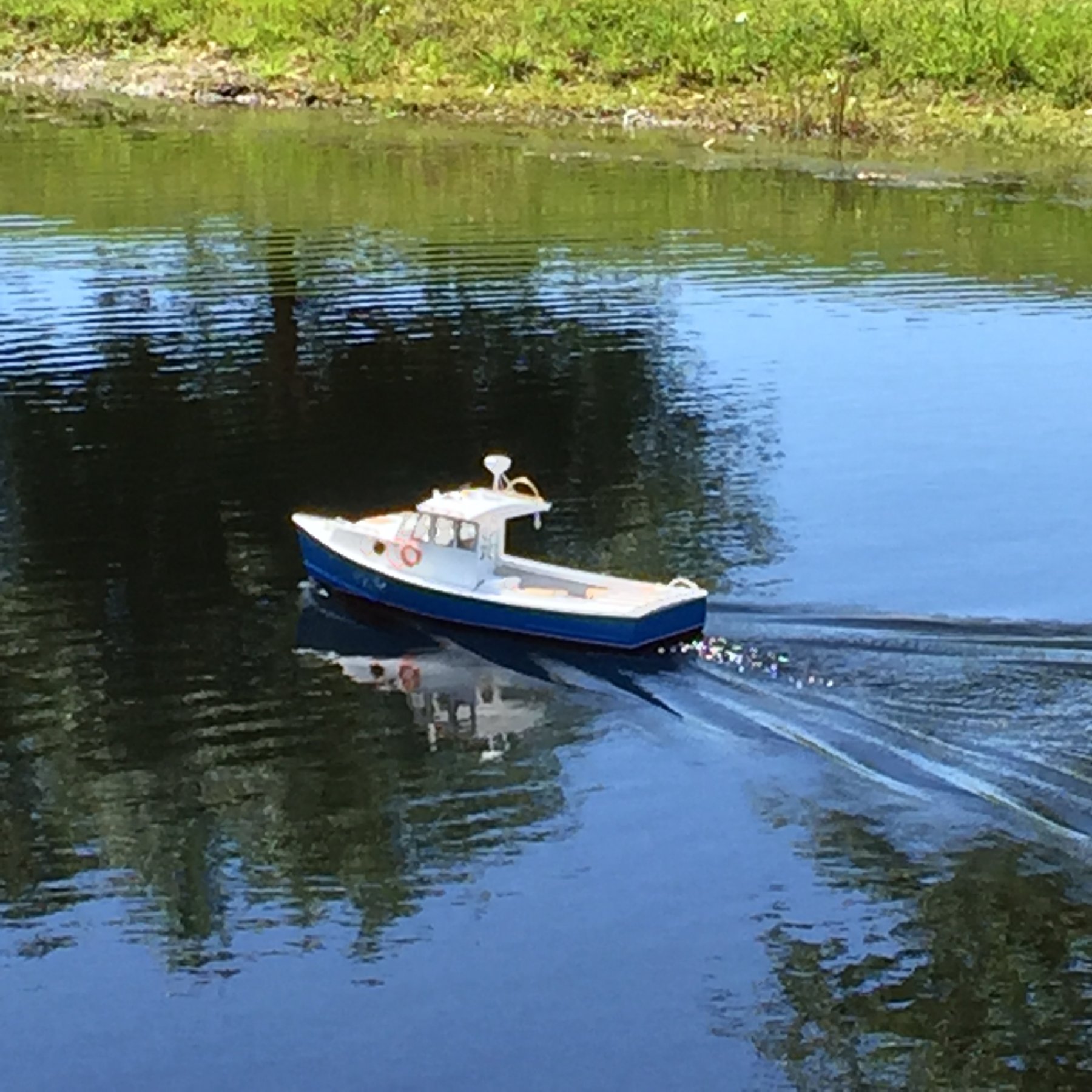
Maine Lobster Boat by Trawlergeek - FINISHED - BlueJacket Shipcrafters - Scale 1:12 - RADIO
schooner reacted to a post in a topic:
Maine Lobster Boat by Trawlergeek - FINISHED - BlueJacket Shipcrafters - Scale 1:12 - RADIO
-
schooner reacted to a post in a topic:
Maine Lobster Boat by Trawlergeek - FINISHED - BlueJacket Shipcrafters - Scale 1:12 - RADIO
-
schooner reacted to a post in a topic:
Maine Lobster Boat by Trawlergeek - FINISHED - BlueJacket Shipcrafters - Scale 1:12 - RADIO
-
schooner reacted to a post in a topic:
Maine Lobster Boat by Trawlergeek - FINISHED - BlueJacket Shipcrafters - Scale 1:12 - RADIO
-
schooner reacted to a post in a topic:
Maine Lobster Boat by Trawlergeek - FINISHED - BlueJacket Shipcrafters - Scale 1:12 - RADIO
-
pythagoras reacted to a post in a topic:
Maine Lobster Boat by Trawlergeek - FINISHED - BlueJacket Shipcrafters - Scale 1:12 - RADIO
-
 Thanks to all. I hope this response finds everyone in good health. Best regards, Jim
 -
Thank you for your very kind comments. The site is very encouraging and has a lot of great contributions. Jim
- 33 replies
-
- 1
-
-
- BlueJacket Shipcrafters
- Maine
- (and 3 more)
-
GrandpaPhil reacted to a post in a topic:
Maine Lobster Boat by Trawlergeek - FINISHED - BlueJacket Shipcrafters - Scale 1:12 - RADIO
-
GrandpaPhil reacted to a post in a topic:
Maine Lobster Boat by Trawlergeek - FINISHED - BlueJacket Shipcrafters - Scale 1:12 - RADIO
-
GrandpaPhil reacted to a post in a topic:
Maine Lobster Boat by Trawlergeek - FINISHED - BlueJacket Shipcrafters - Scale 1:12 - RADIO
-
GrandpaPhil reacted to a post in a topic:
Maine Lobster Boat by Trawlergeek - FINISHED - BlueJacket Shipcrafters - Scale 1:12 - RADIO
-
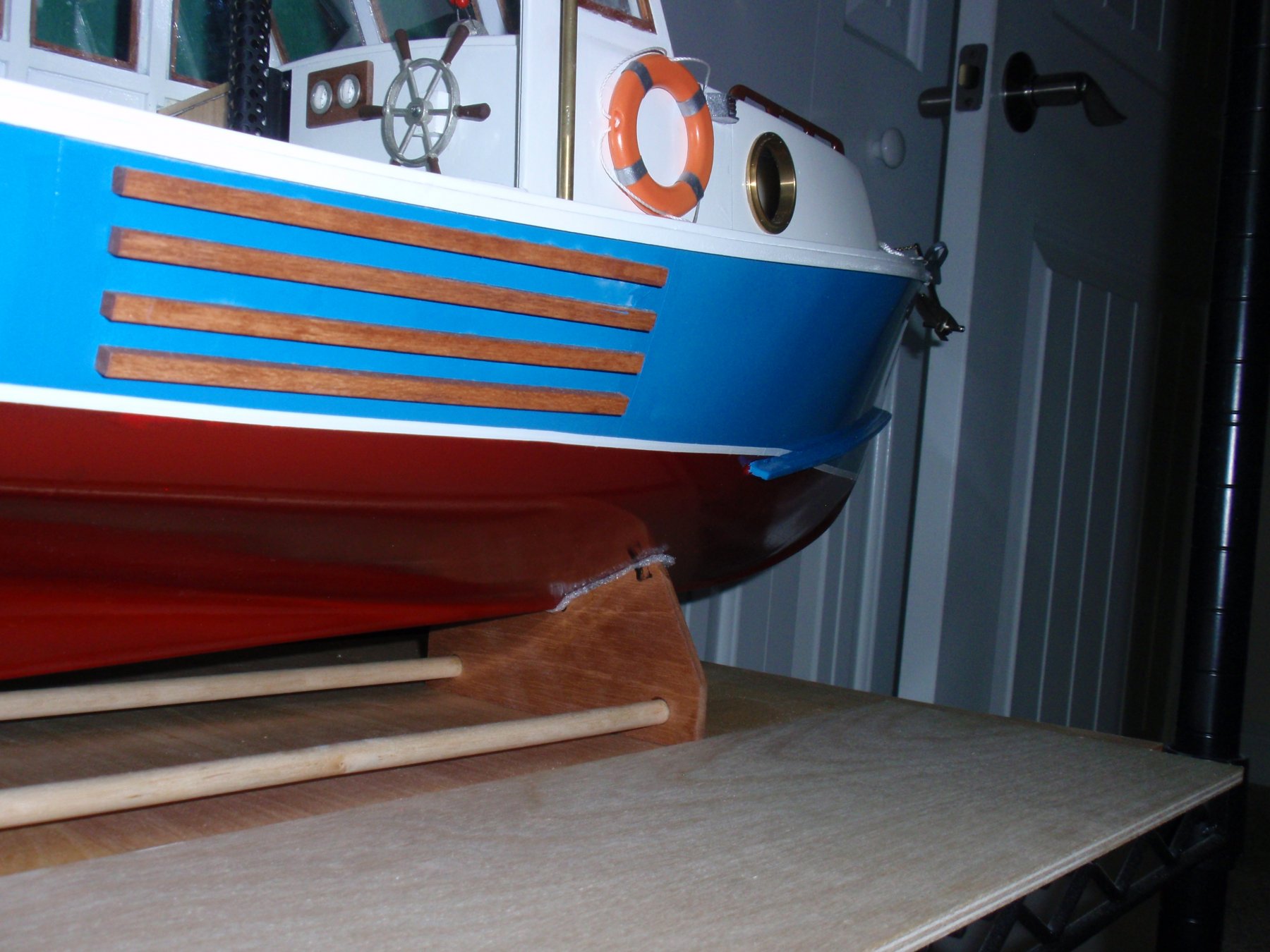
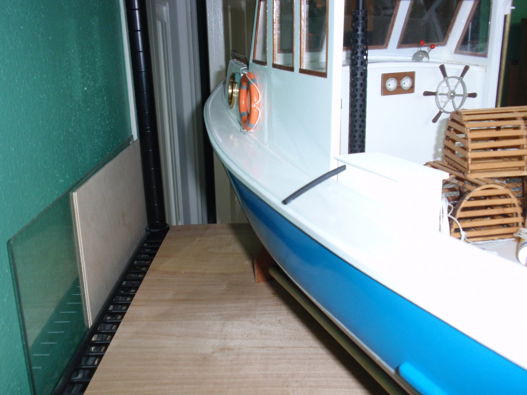
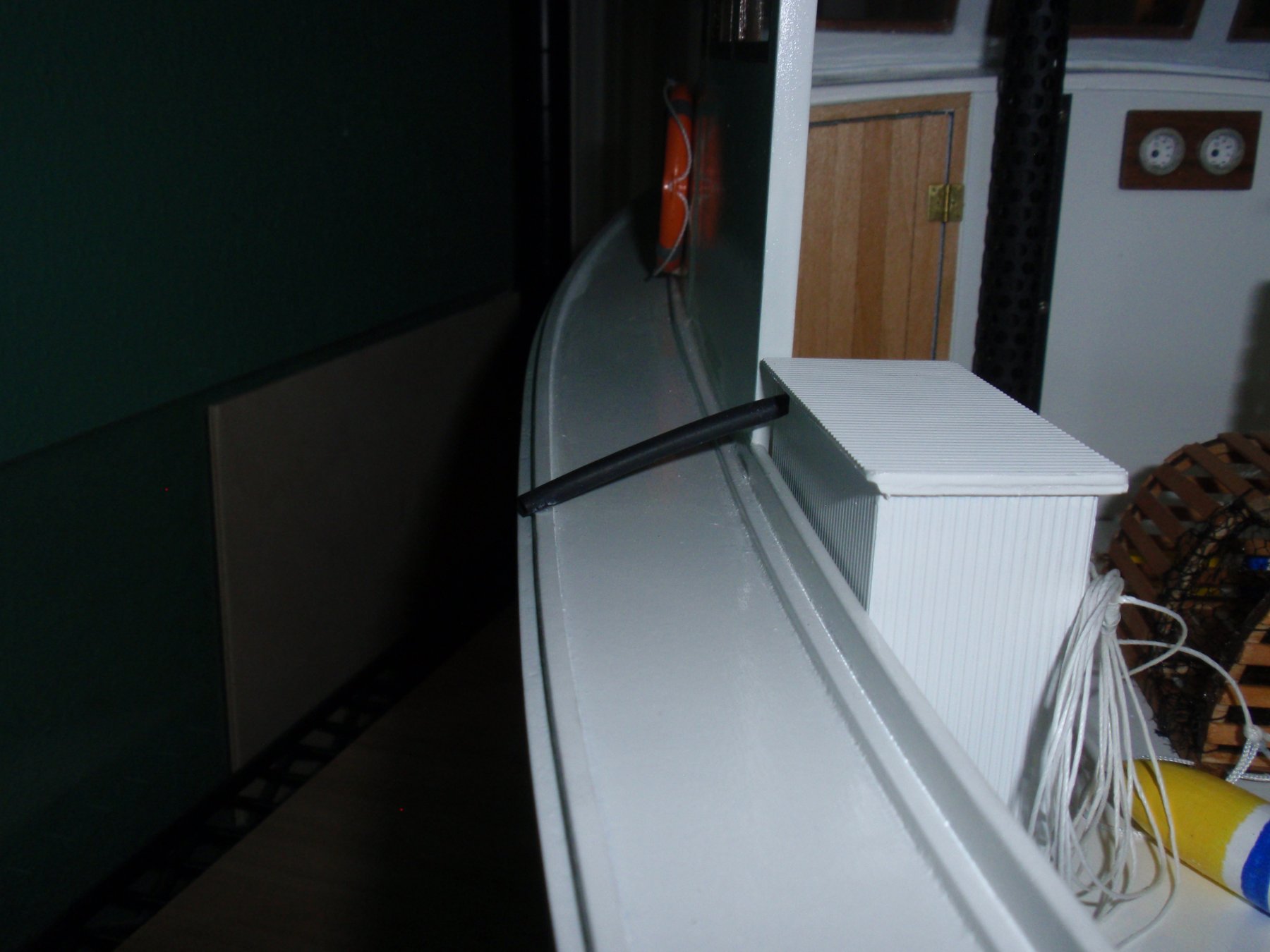
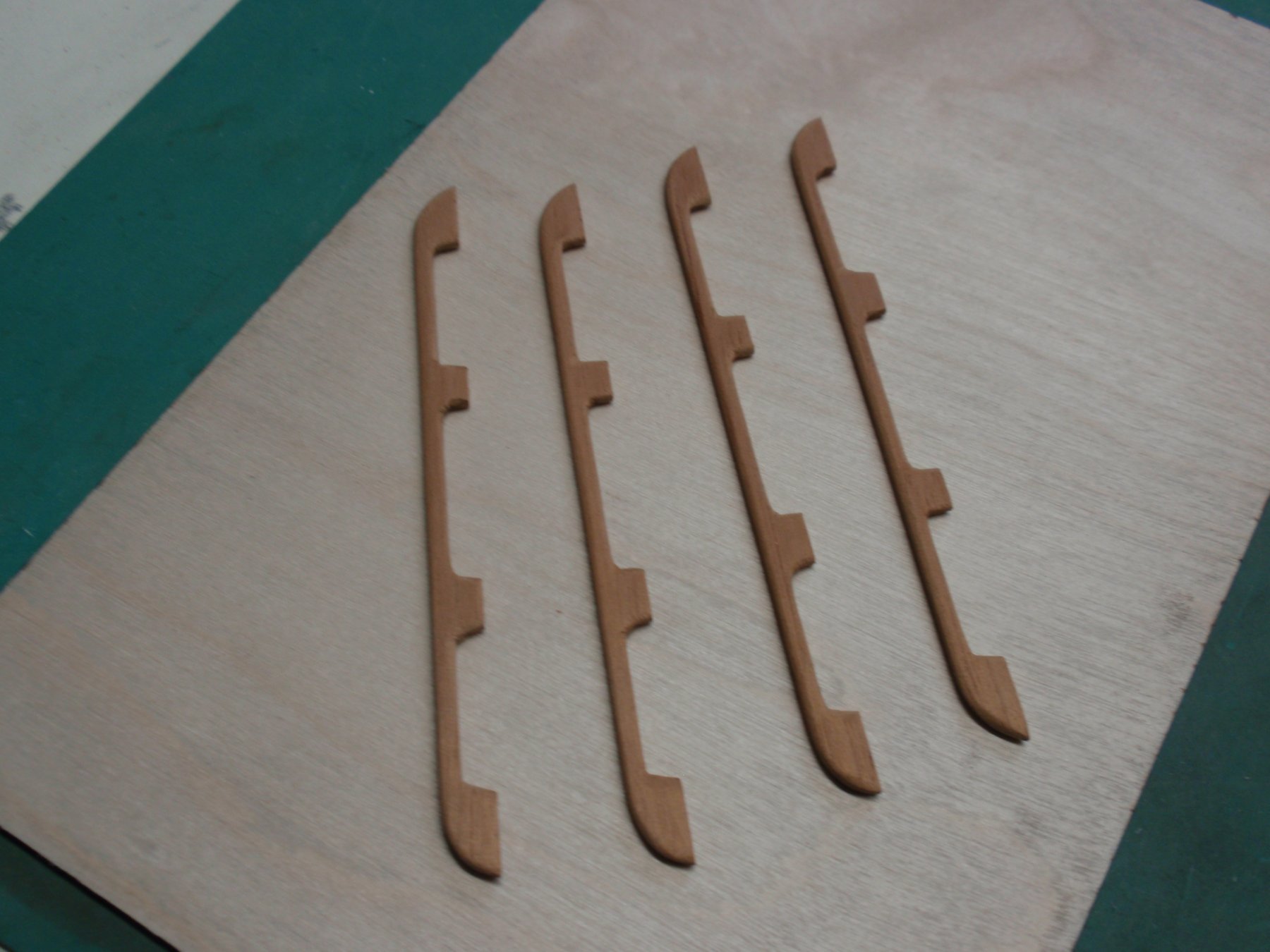
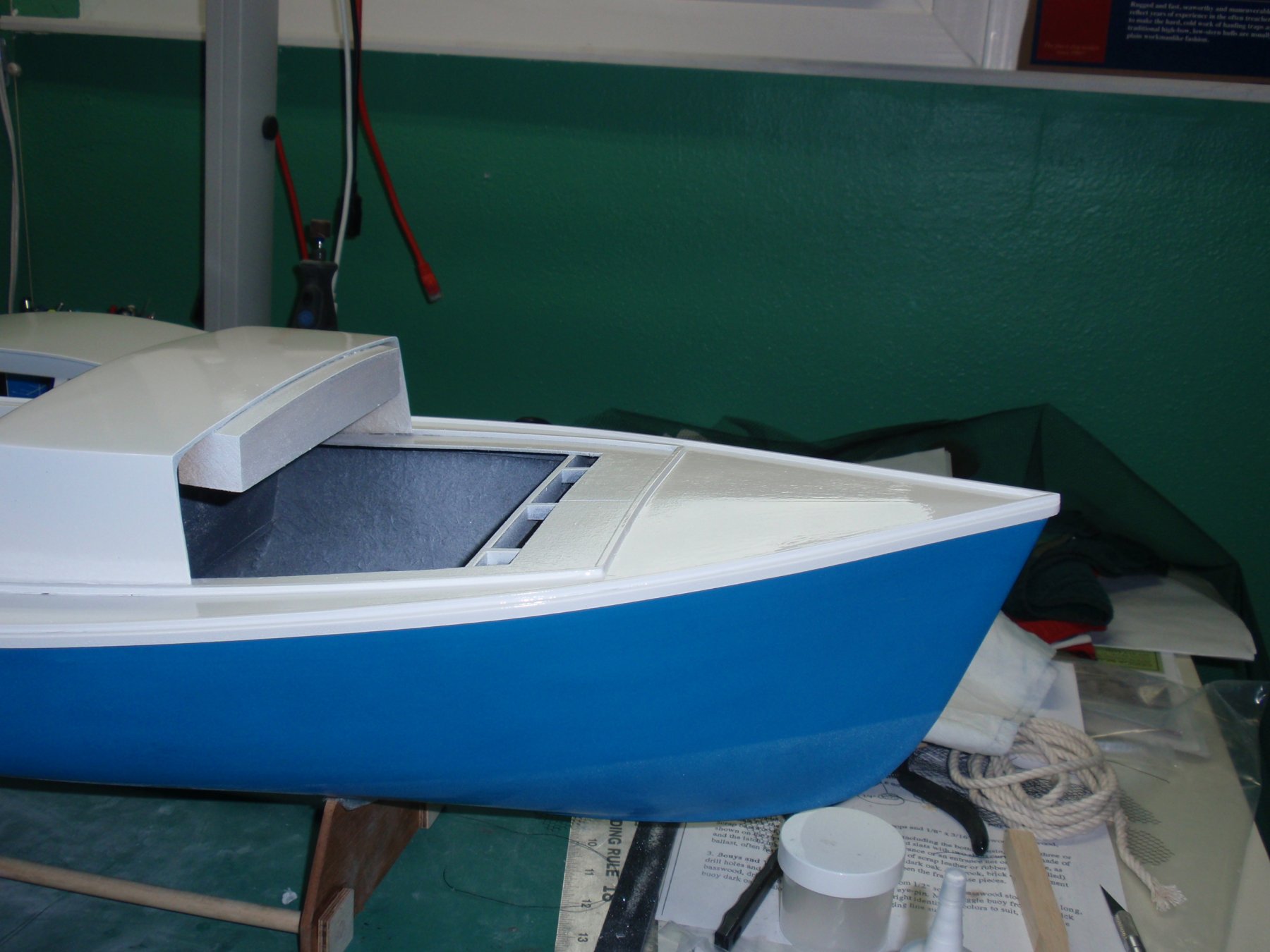
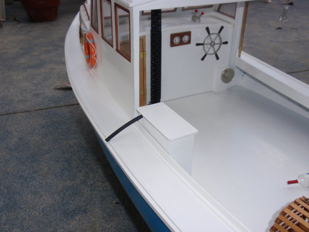
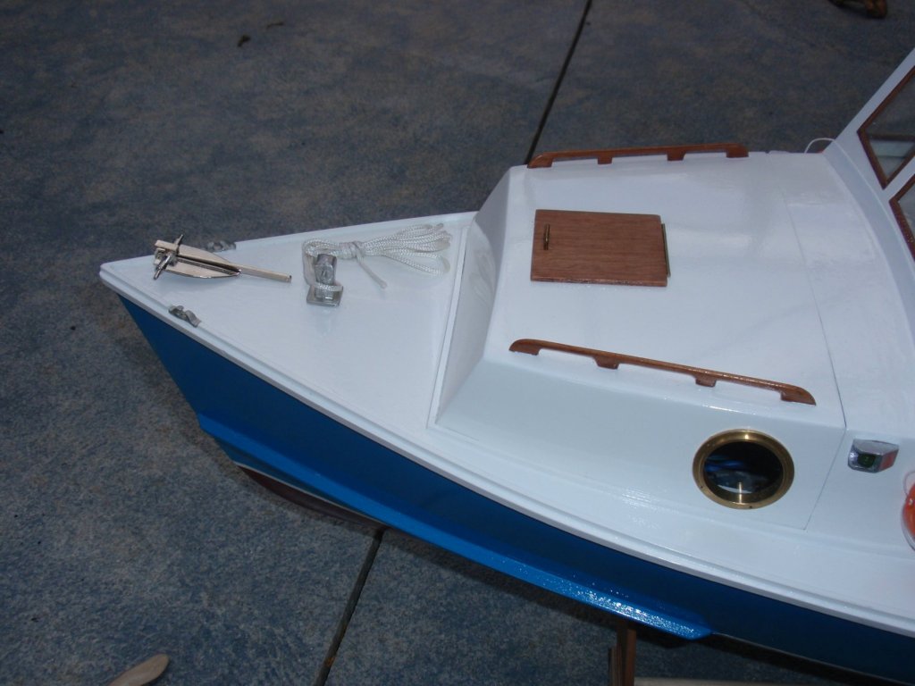
Installment #22 Finishing Details To keep this boat dry, I added spray rails in the bow section. Very satisfying results.


- 33 replies
-
- 3
-
-
- BlueJacket Shipcrafters
- Maine
- (and 3 more)
-
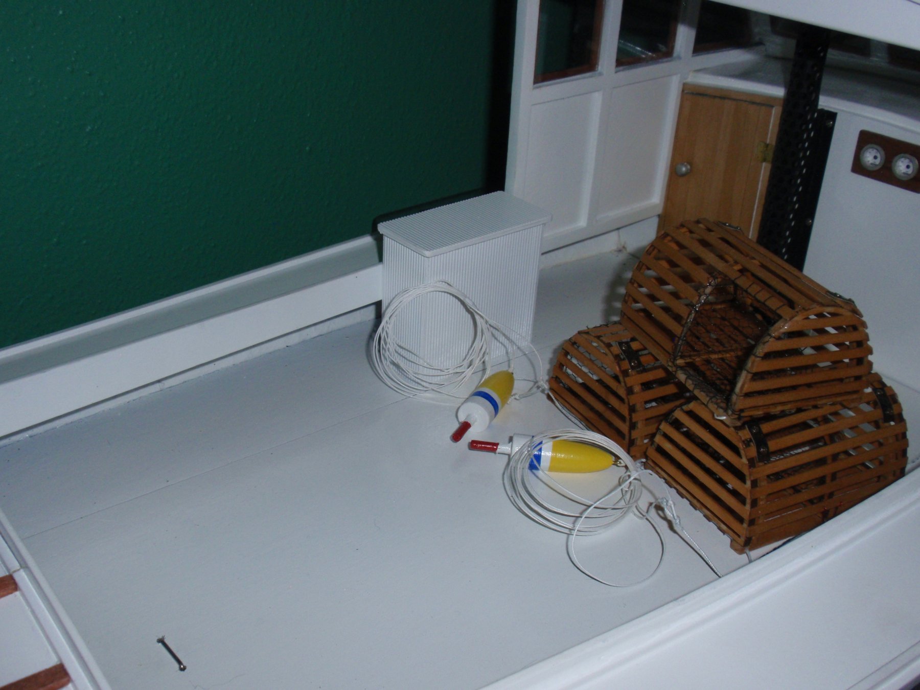
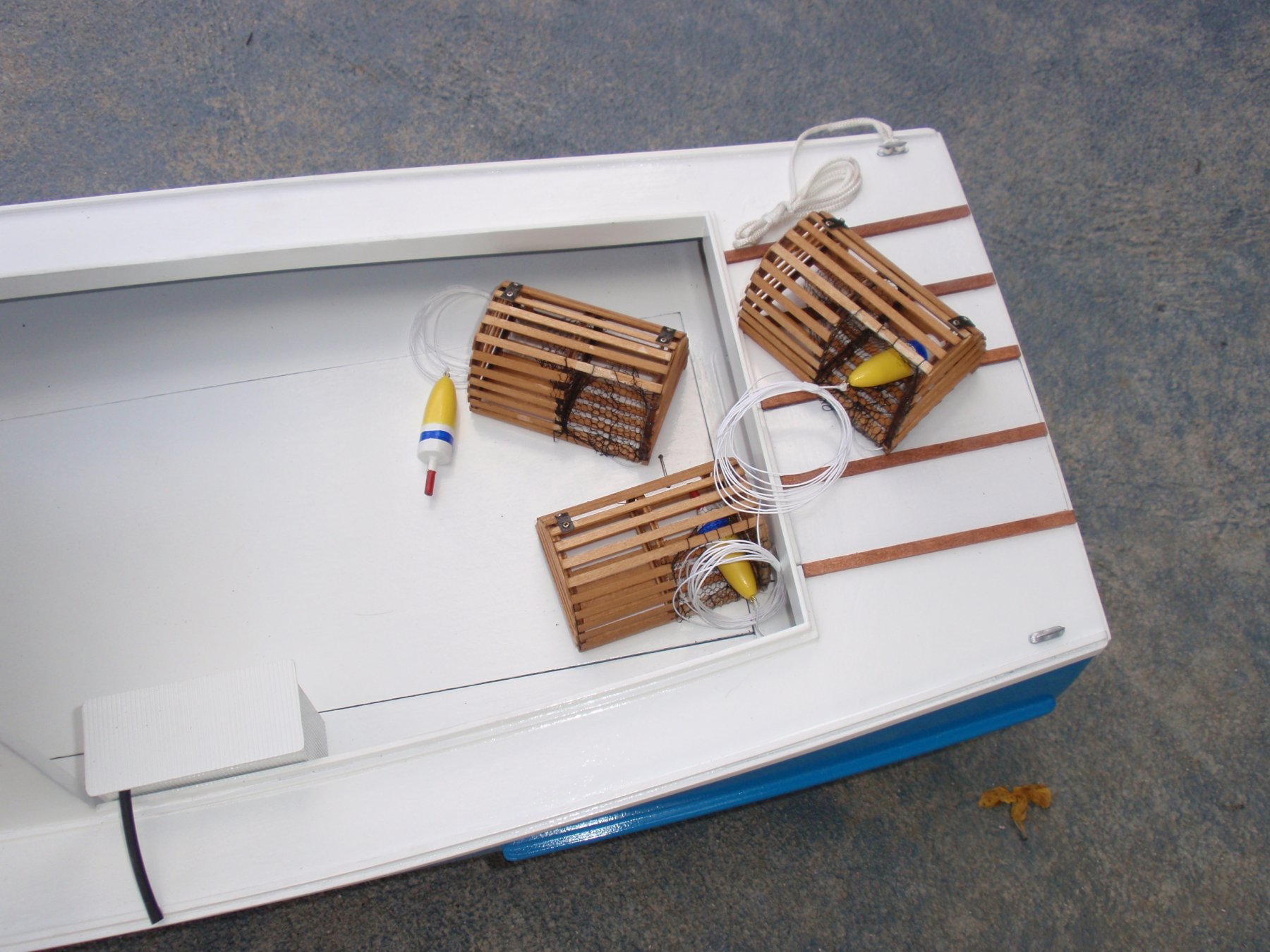
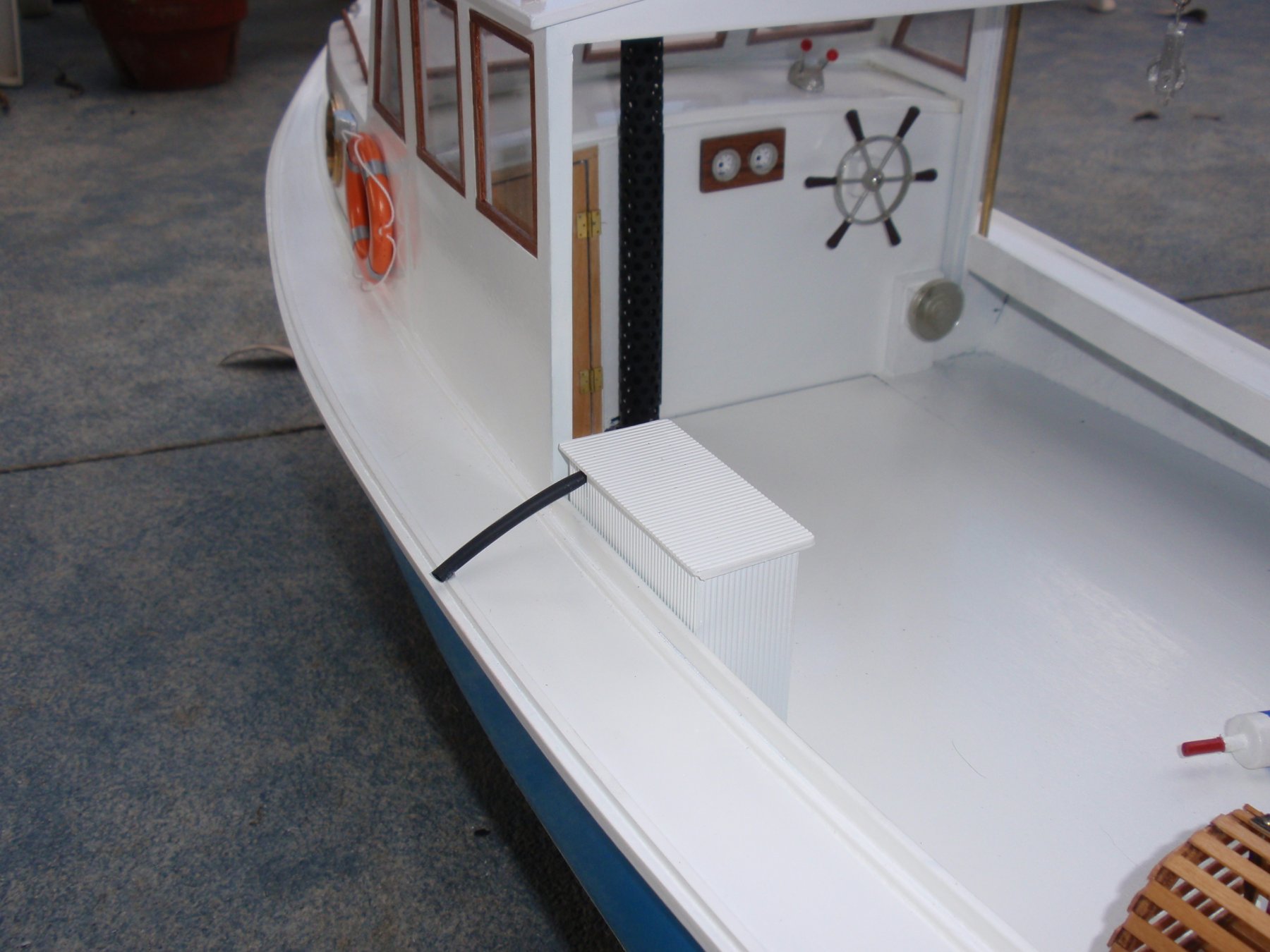
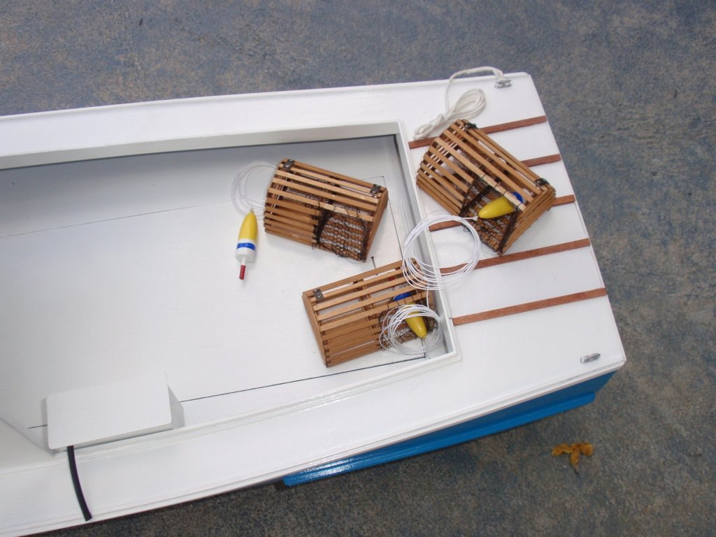
Installment #21 Finishing Details - Lobster Tank, Live Well


- 33 replies
-
- 3
-
-
- BlueJacket Shipcrafters
- Maine
- (and 3 more)
-
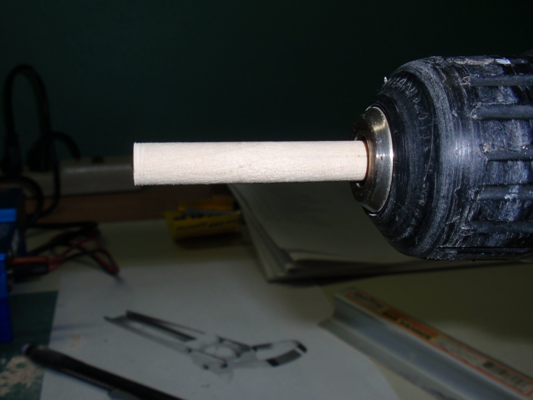
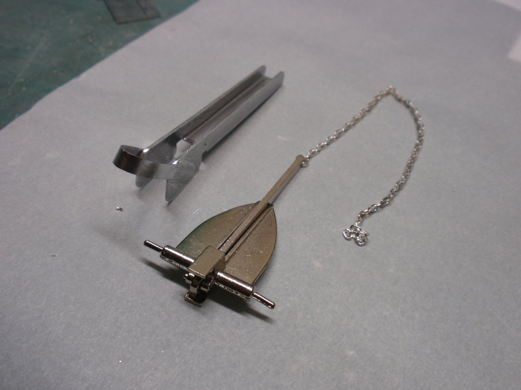
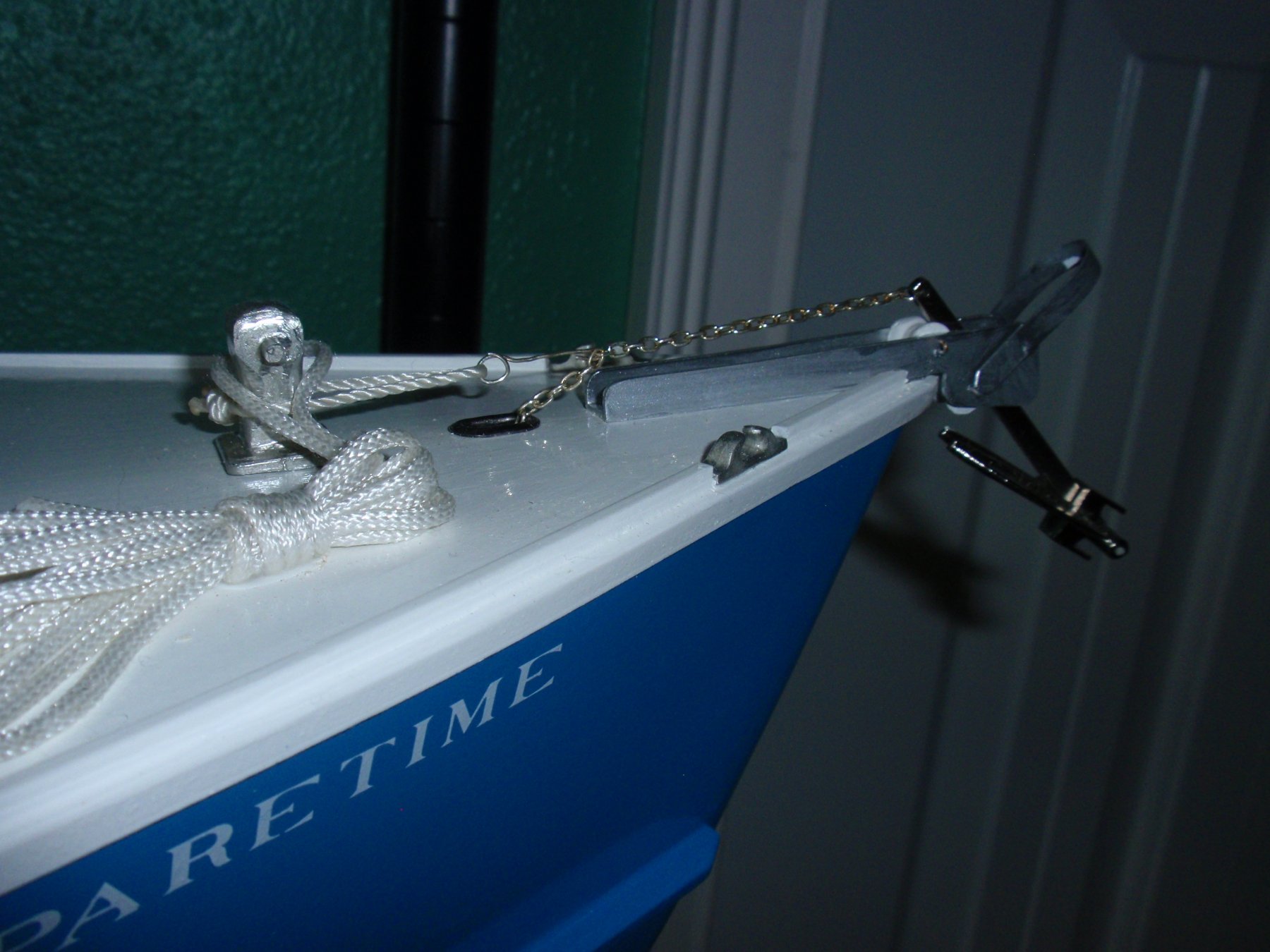
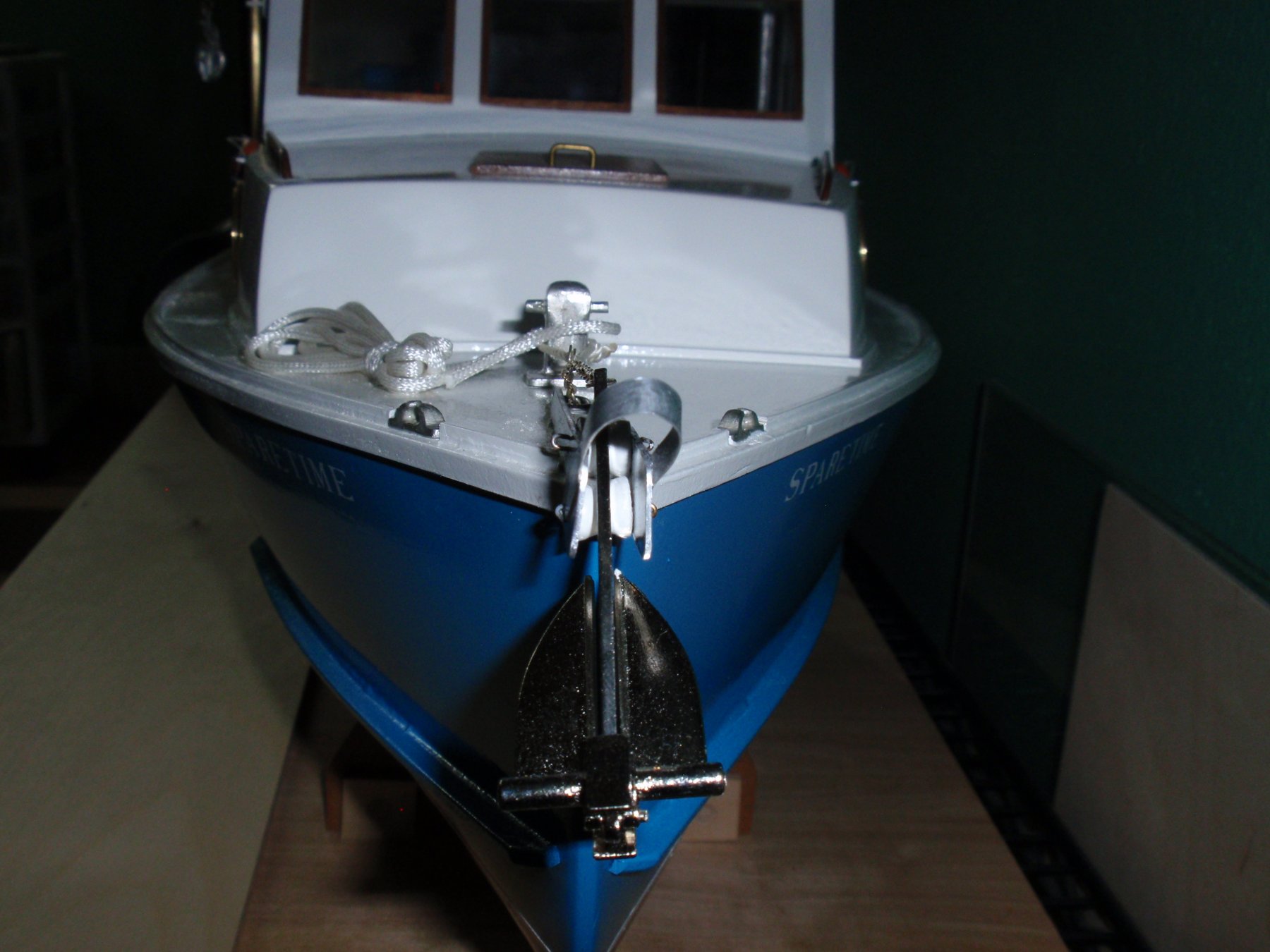
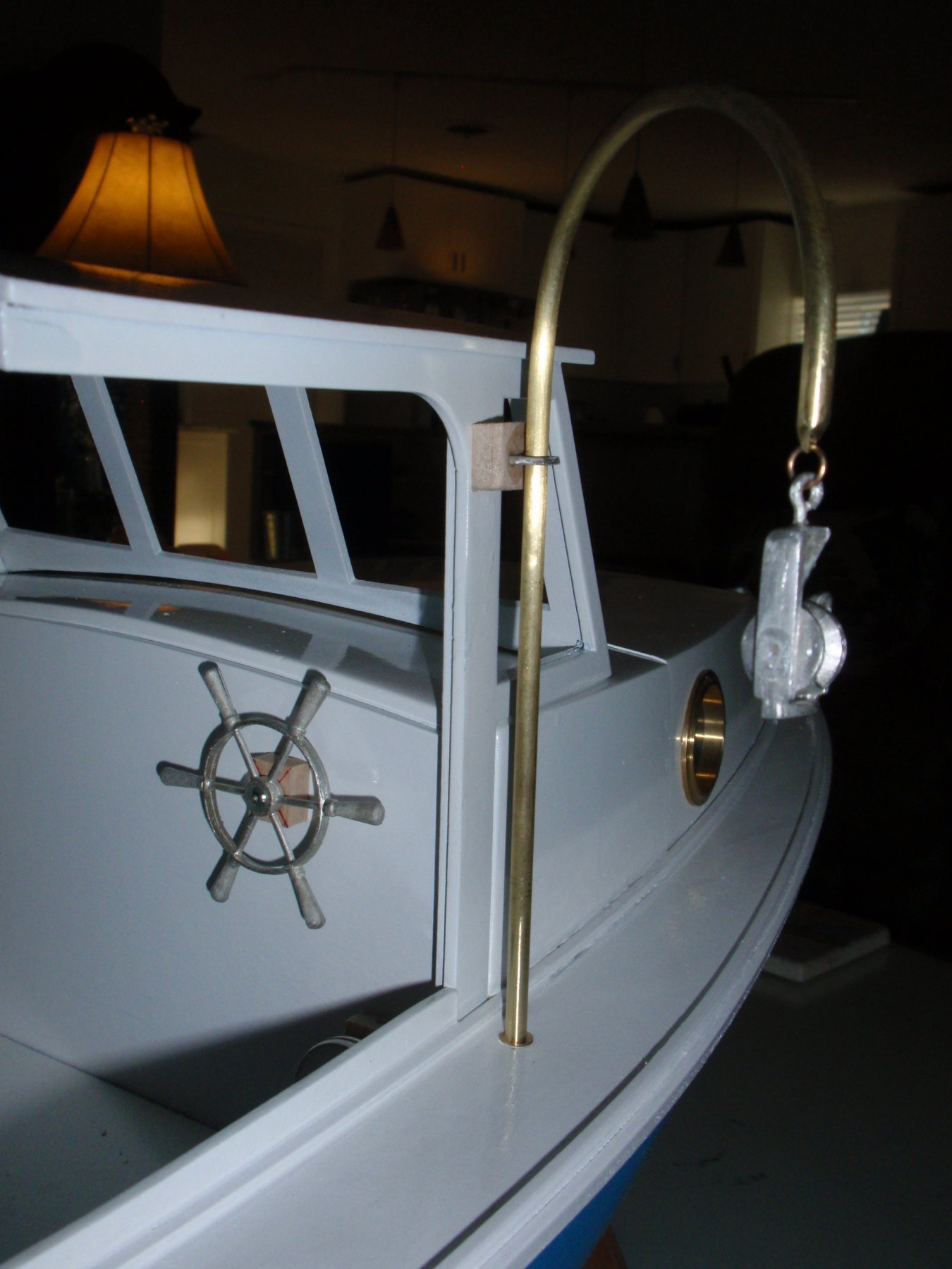
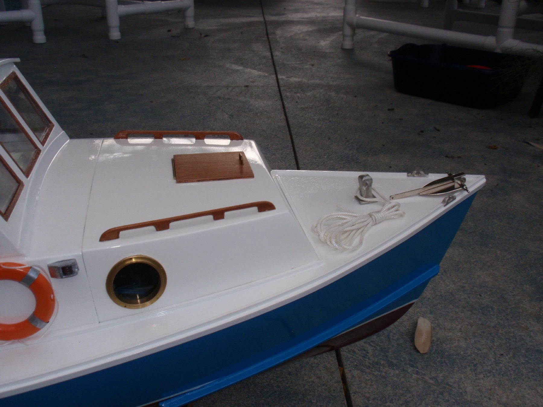
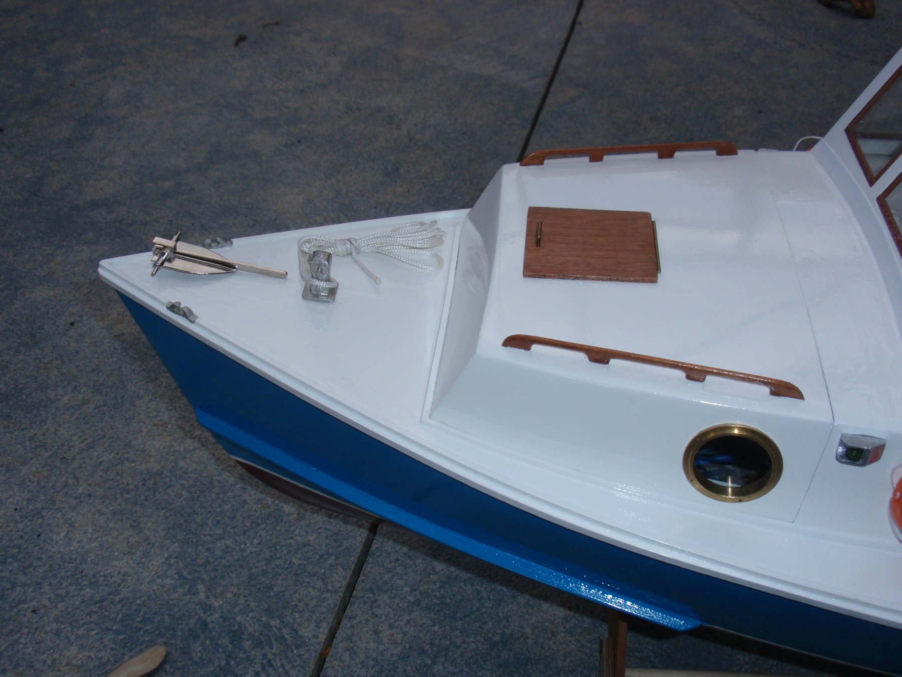
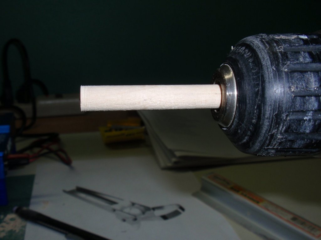
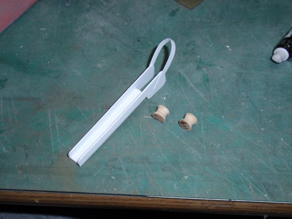
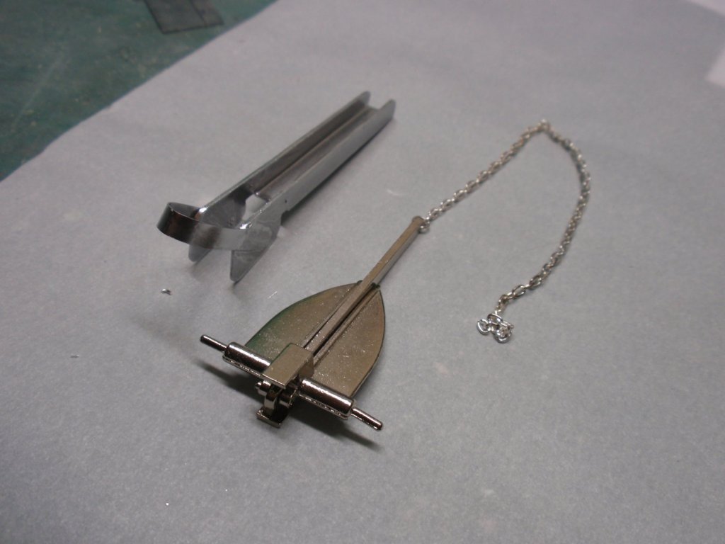
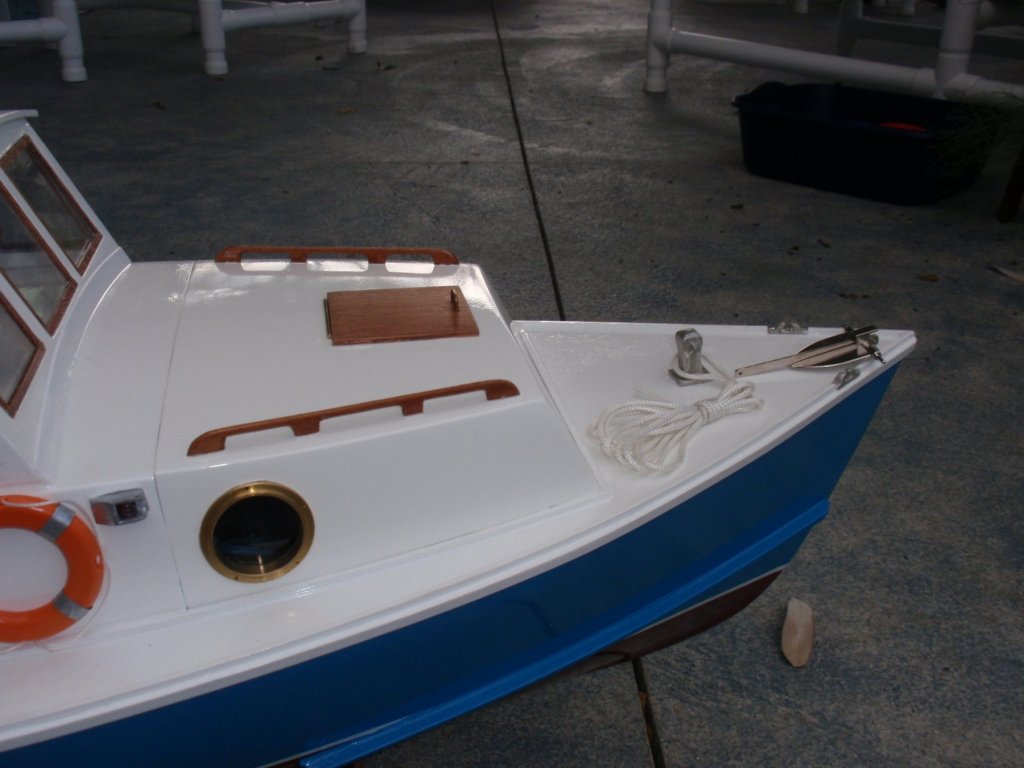
Installment #20 Finishing Details - Anchor Davit A drill works fairly well as a lathe for small wooden items.


- 33 replies
-
- 3
-
-
- BlueJacket Shipcrafters
- Maine
- (and 3 more)
-
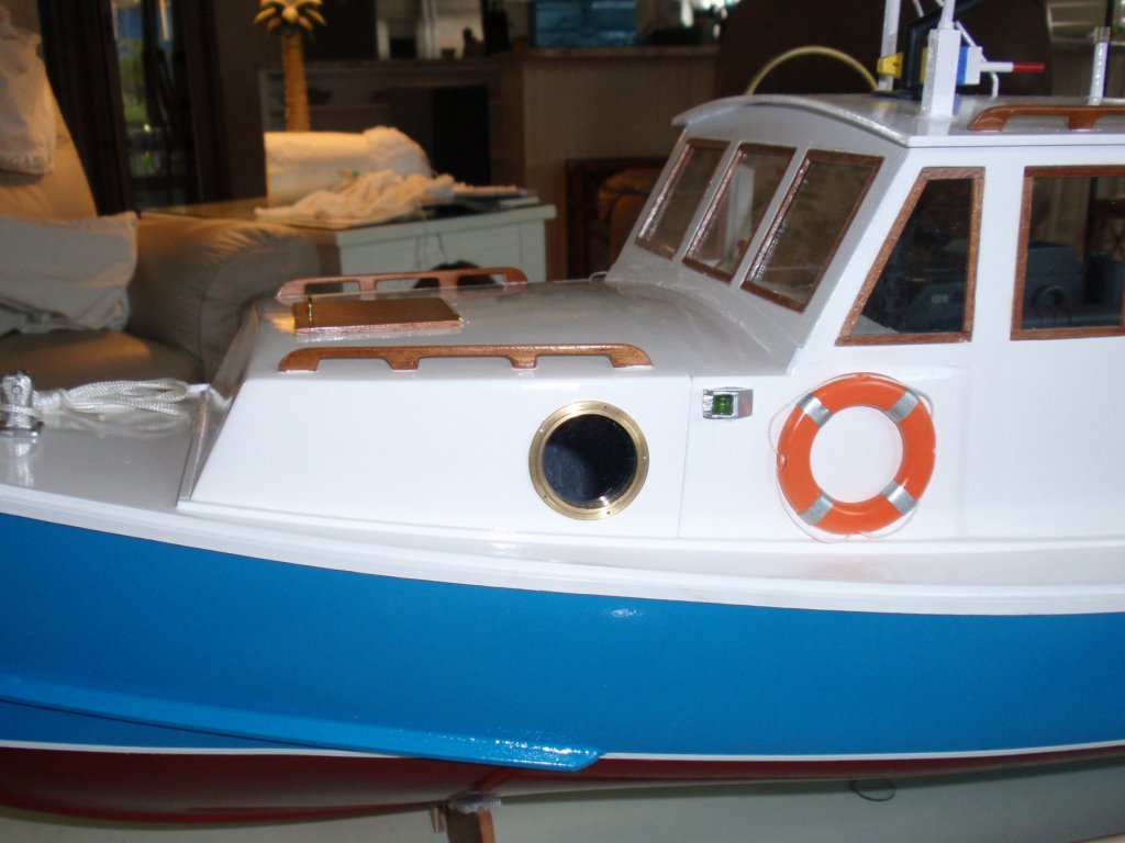
Installment #19 Finishing Details - Continued I made custom port and starboard lights using balsa blocks. I added some beads for the actual lights. In this picture, you can see the light veneer applied at the bottom of the front facing windshield where it intersects with the fiberglass cabin roof.


- 33 replies
-
- 3
-
-
- BlueJacket Shipcrafters
- Maine
- (and 3 more)
-
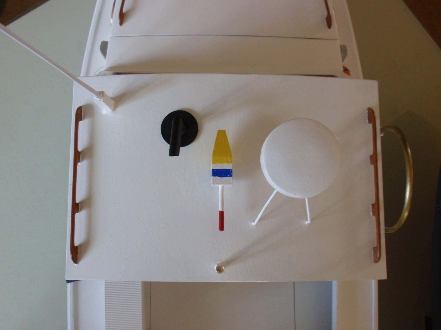
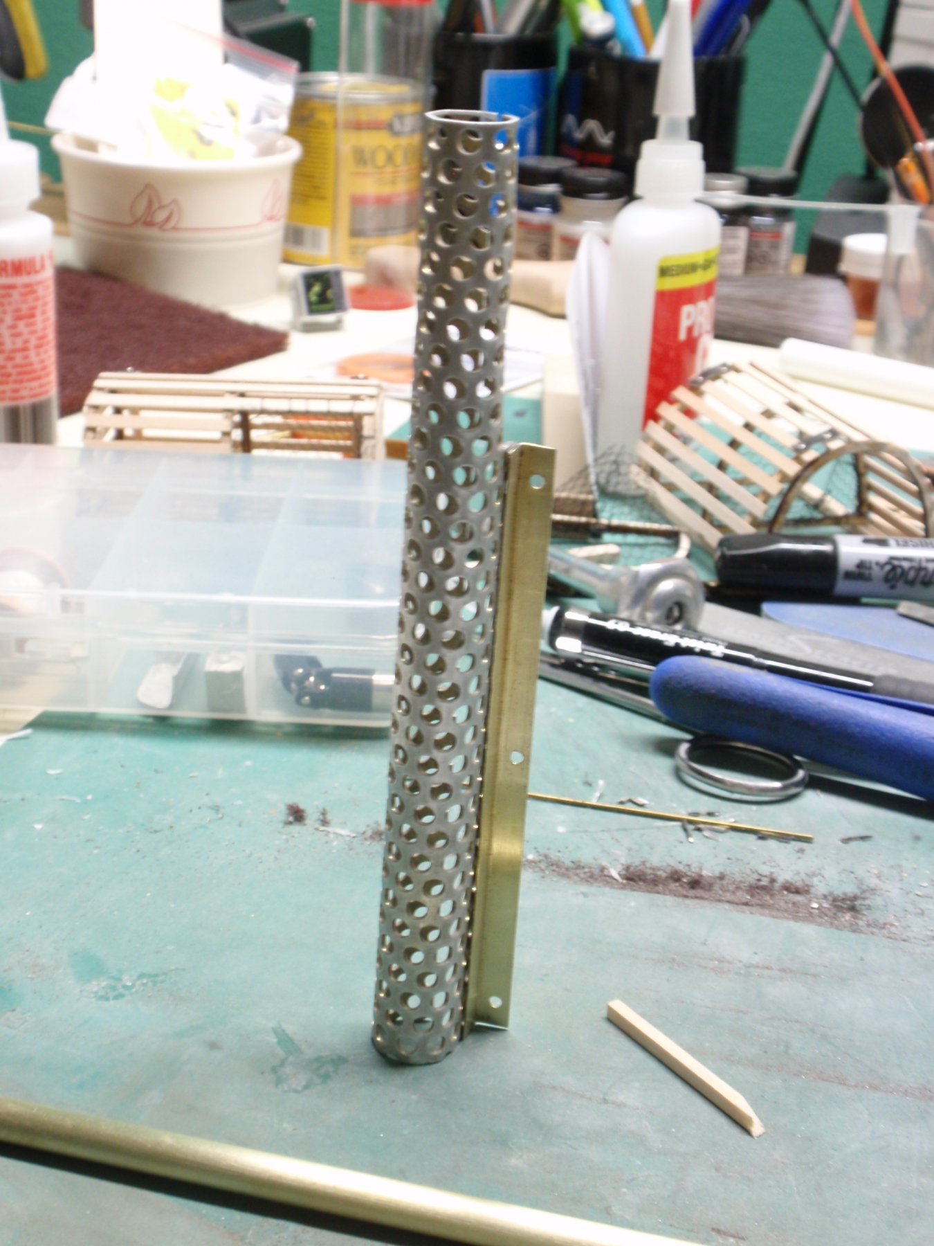
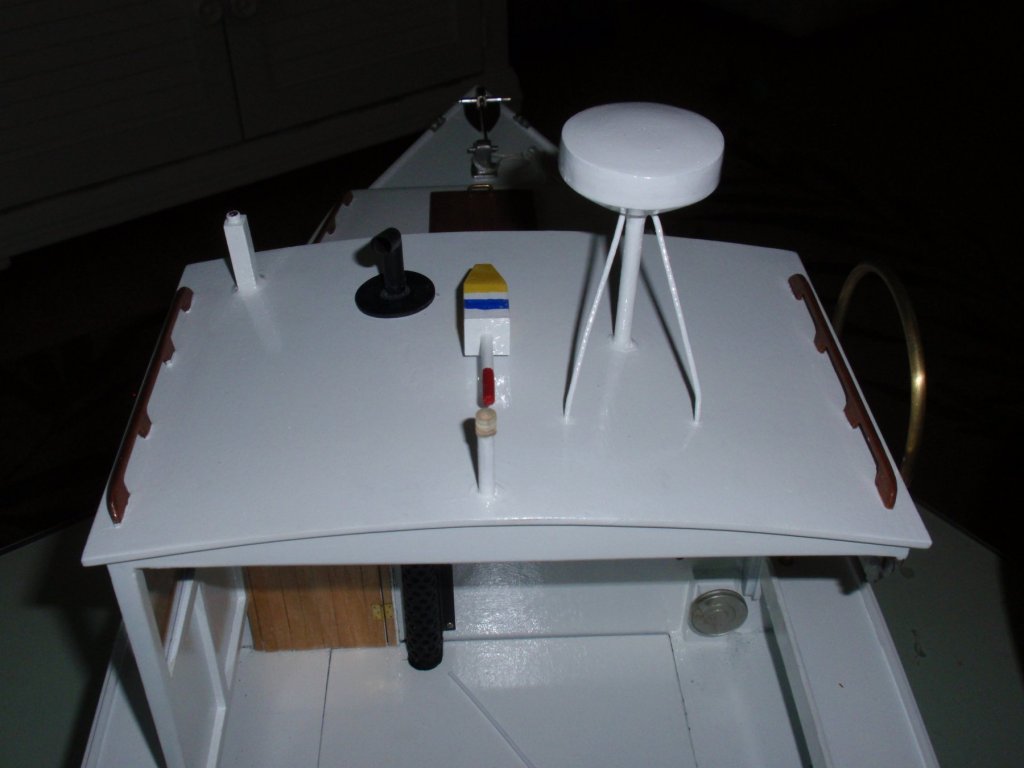
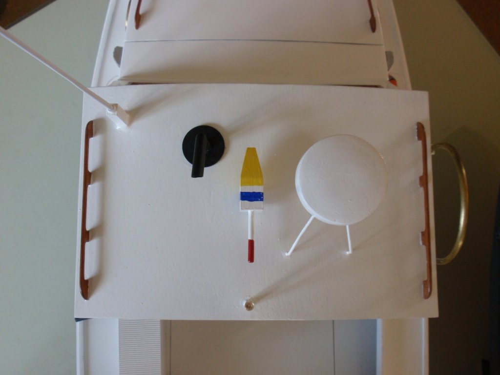
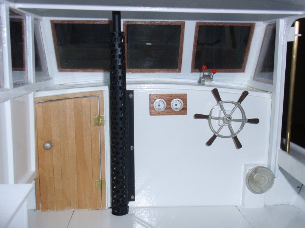
Installment #18 Finishing Details This installment contains a smattering of pictures and comments regarding the finished details. Exhaust stack details...

- 33 replies
-
- 3
-
-
- BlueJacket Shipcrafters
- Maine
- (and 3 more)
-
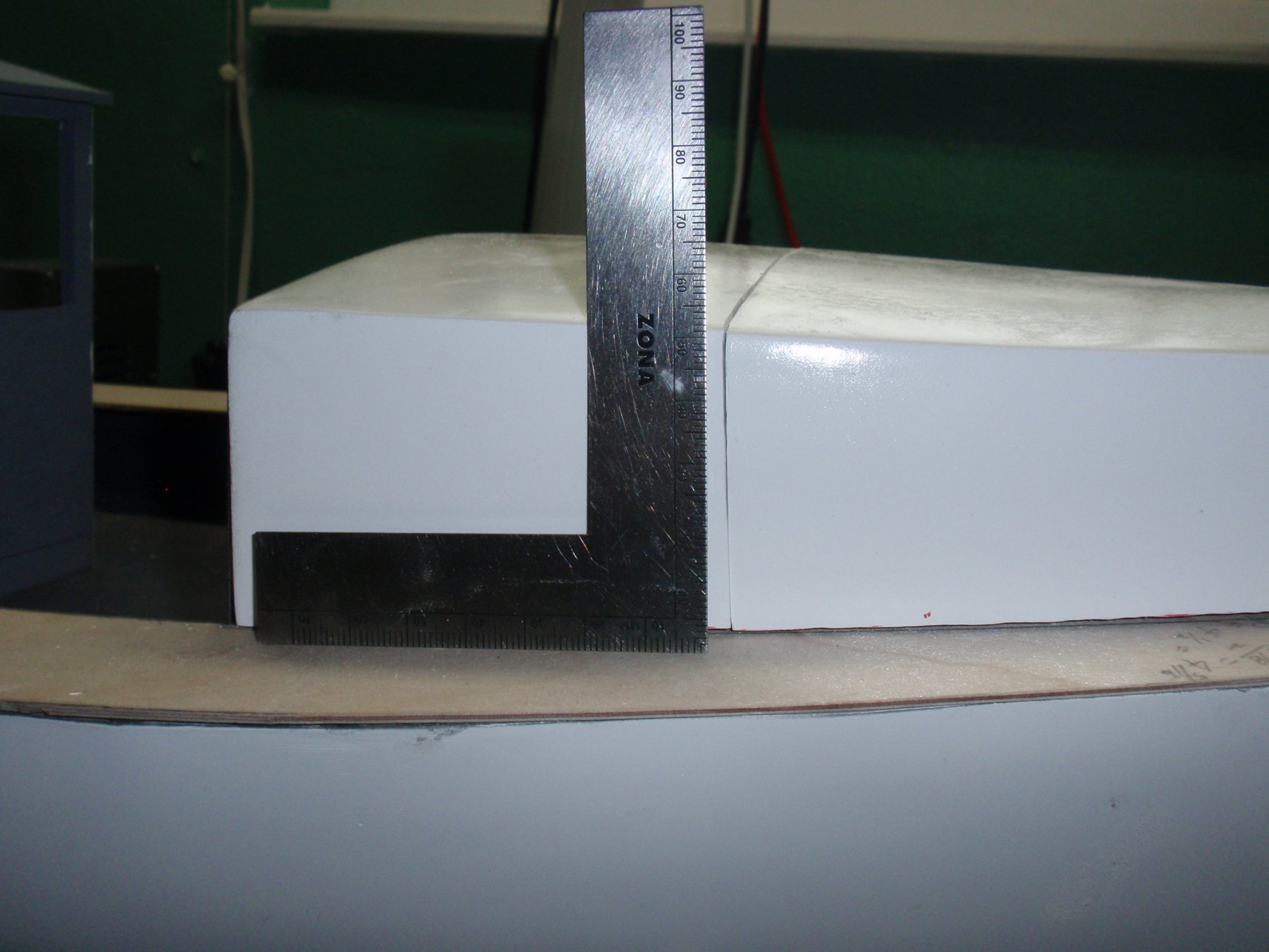
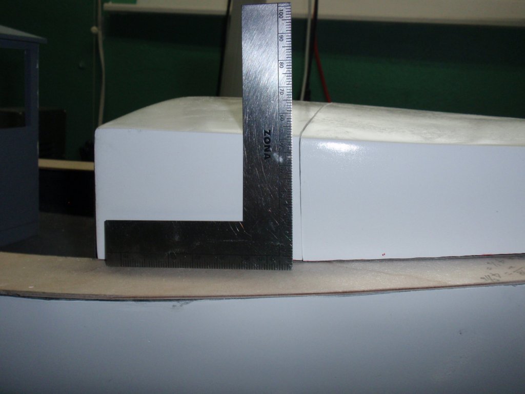
Installment #17 Fiberglass Cabin The fiberglass cabin must be cut into two pieces - fore and aft. The cut line must be established well forward of the line where the windshield intersects the fiberglass cabin. Looking back at Installment 4, there is described a rotary tool that looks like a saw blade. The blade was used to cut the fiberglass cabin roof after carefully scribeing a line using small squares and "bendy" rulers. This step required great patience and investment of time. The cabin is made of pretty well reinforced glass and thus takes time to cut through cleanly. A before picture... (Notice the gap between the windshield and the fiberglass cabin roof. This is handled later.) Inscribing the cut lines... C Afterwards... Add the reinforcing block to the permanently attached roof section... A small square trimmer is attached that follows the deck outline of the cabin pieces... Not show here are two small plywood tabs taht are attached to the sides of the cabin roof removable section that engage the interior sides of the fixed cabin roof section. The tabls are glued to the removable section only.


- 33 replies
-
- 2
-
-
- BlueJacket Shipcrafters
- Maine
- (and 3 more)
-
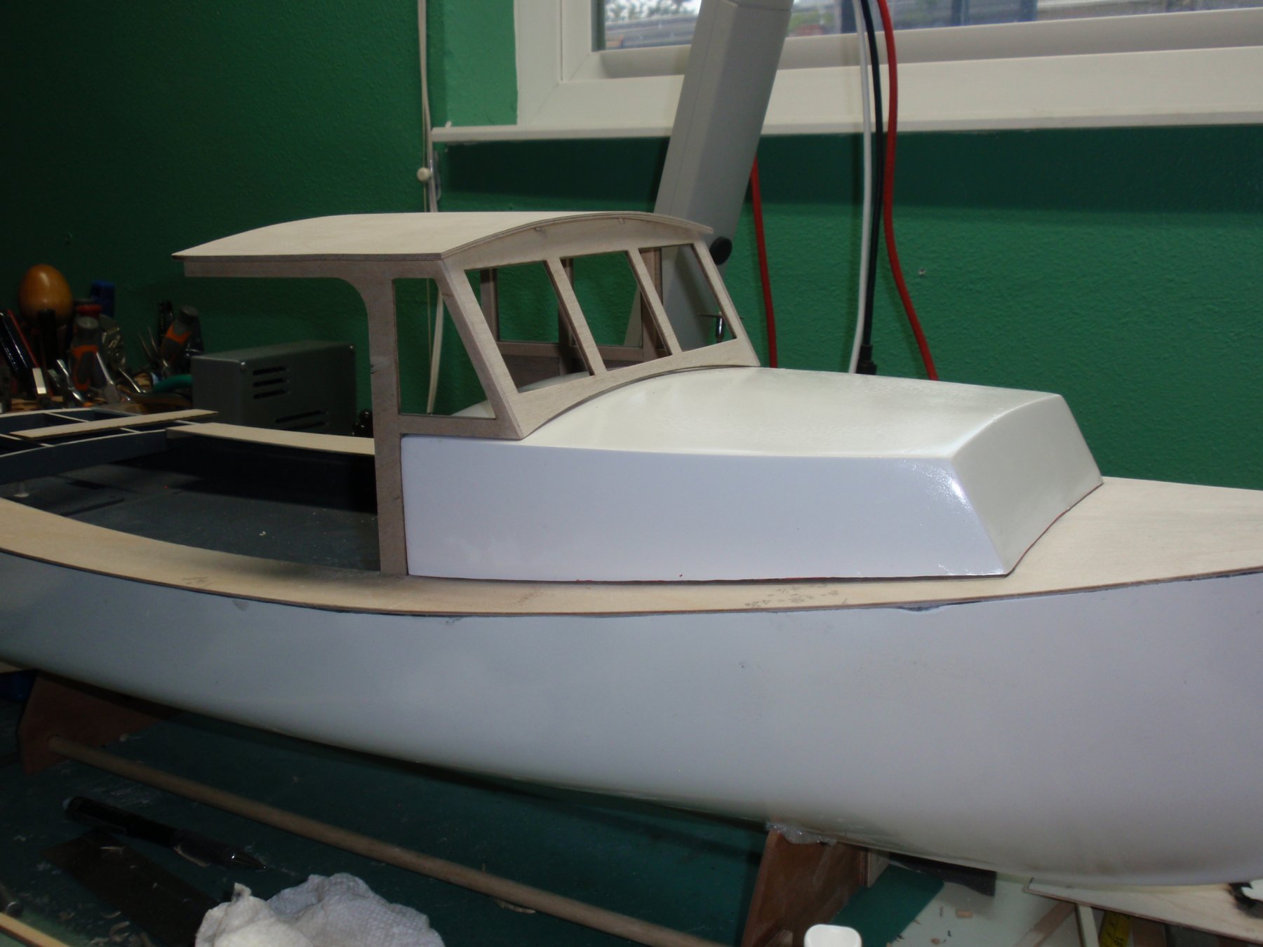
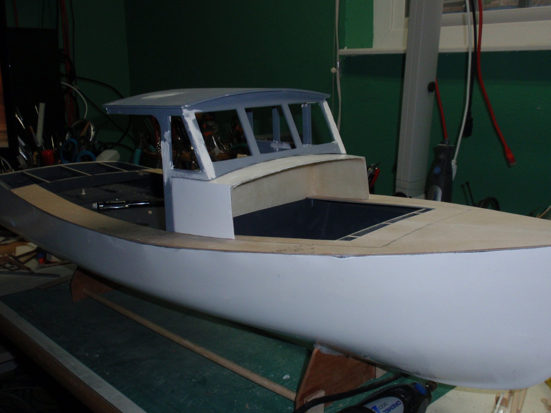
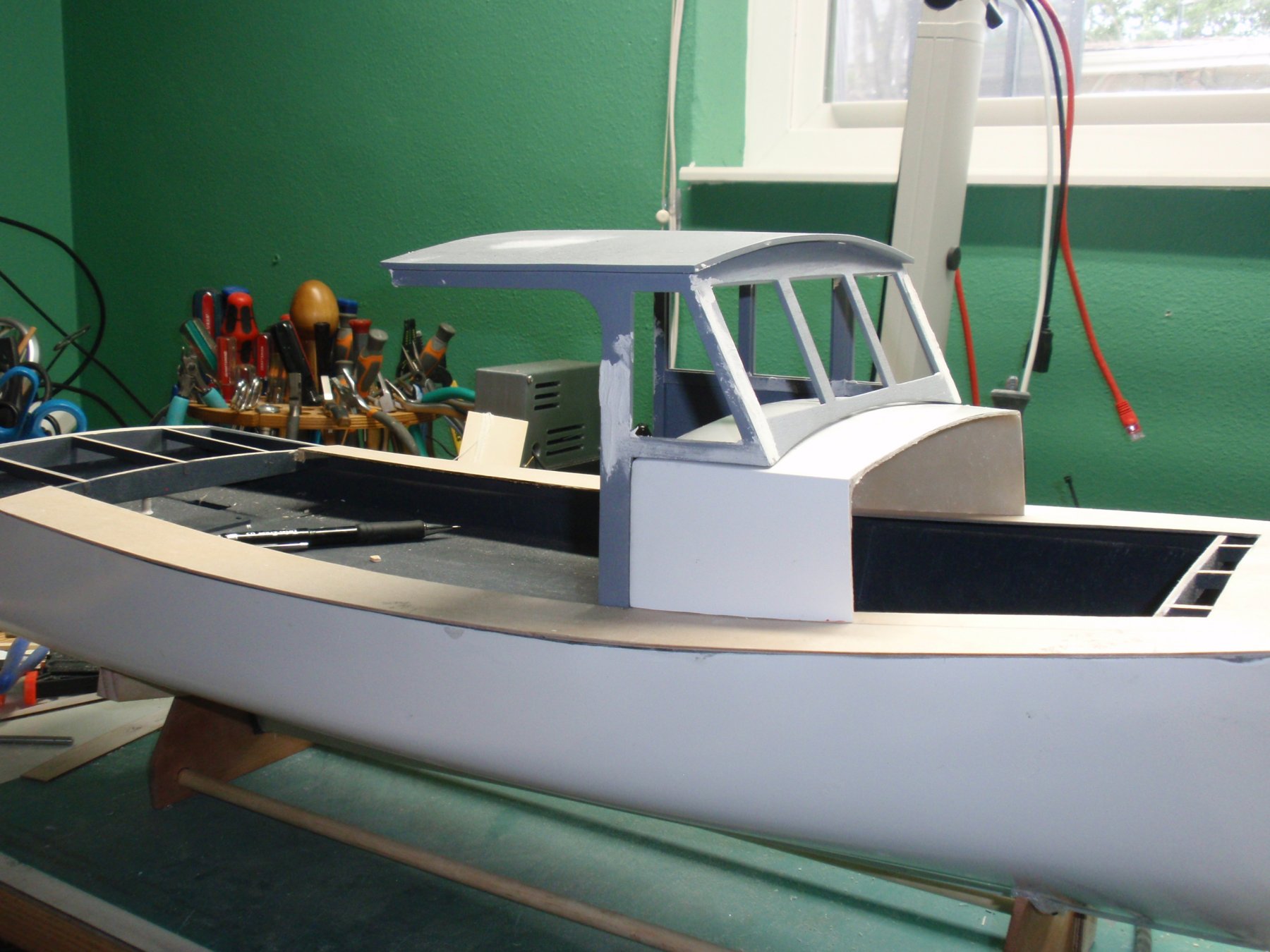
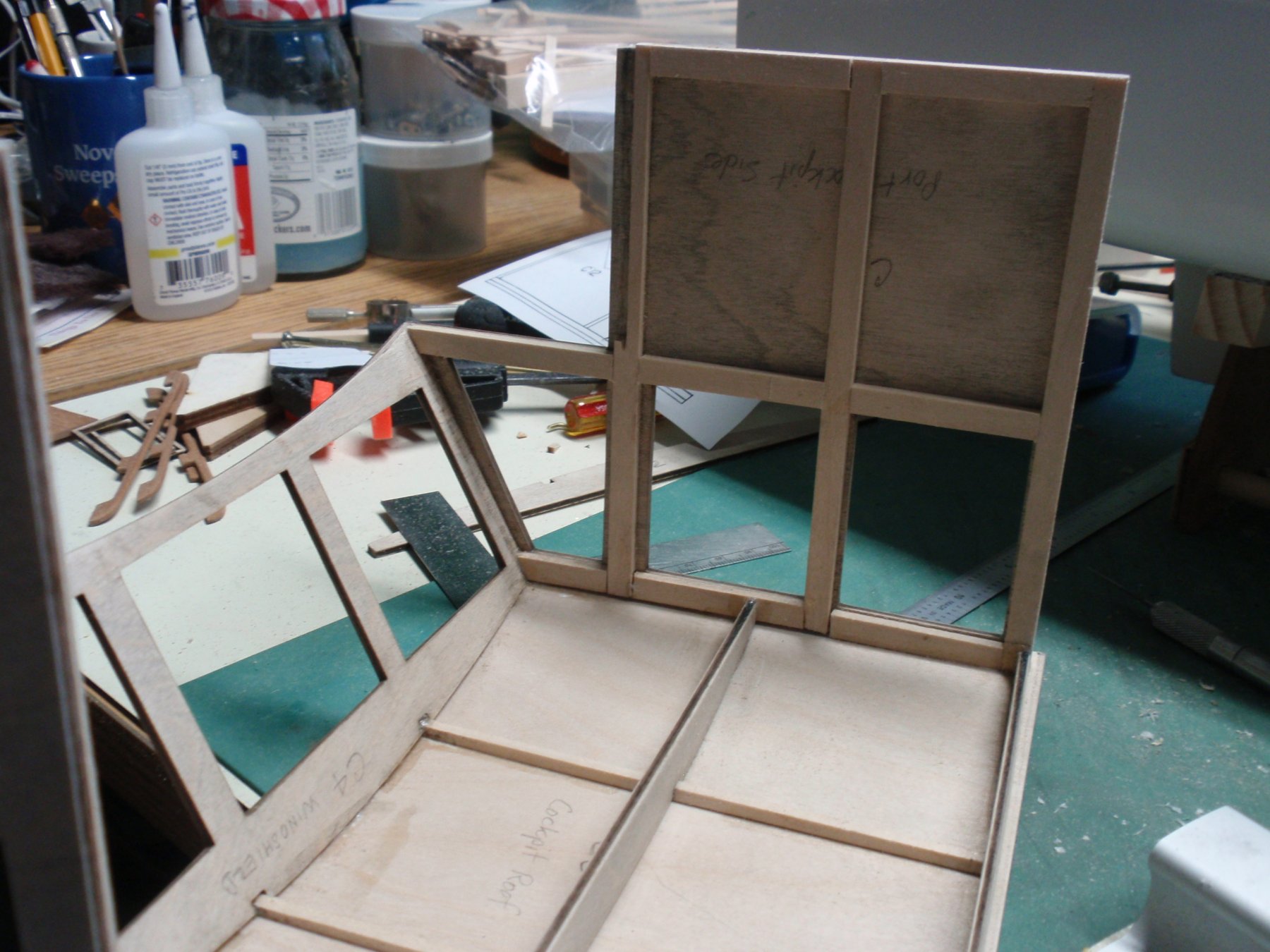
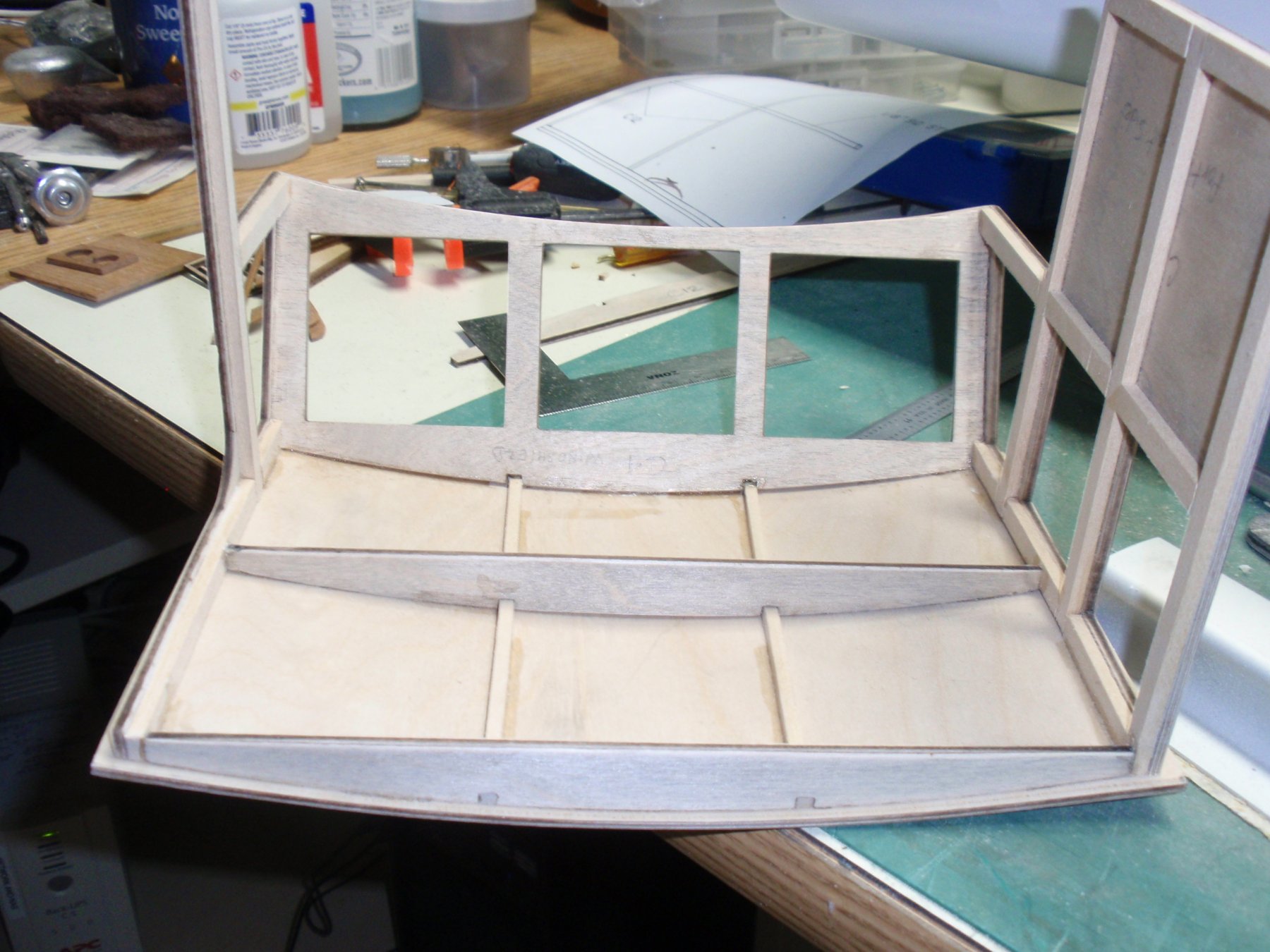
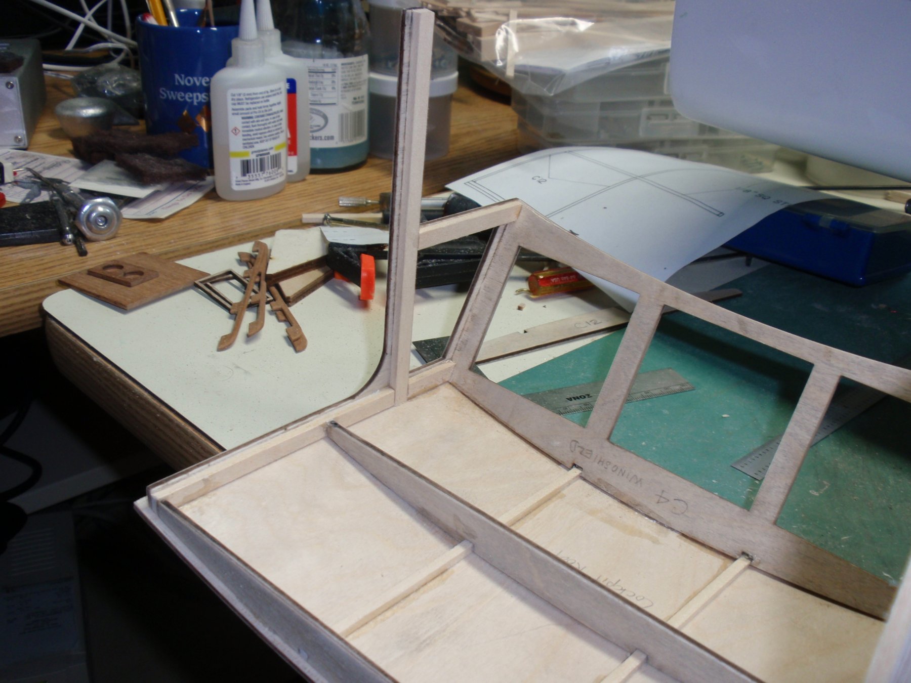
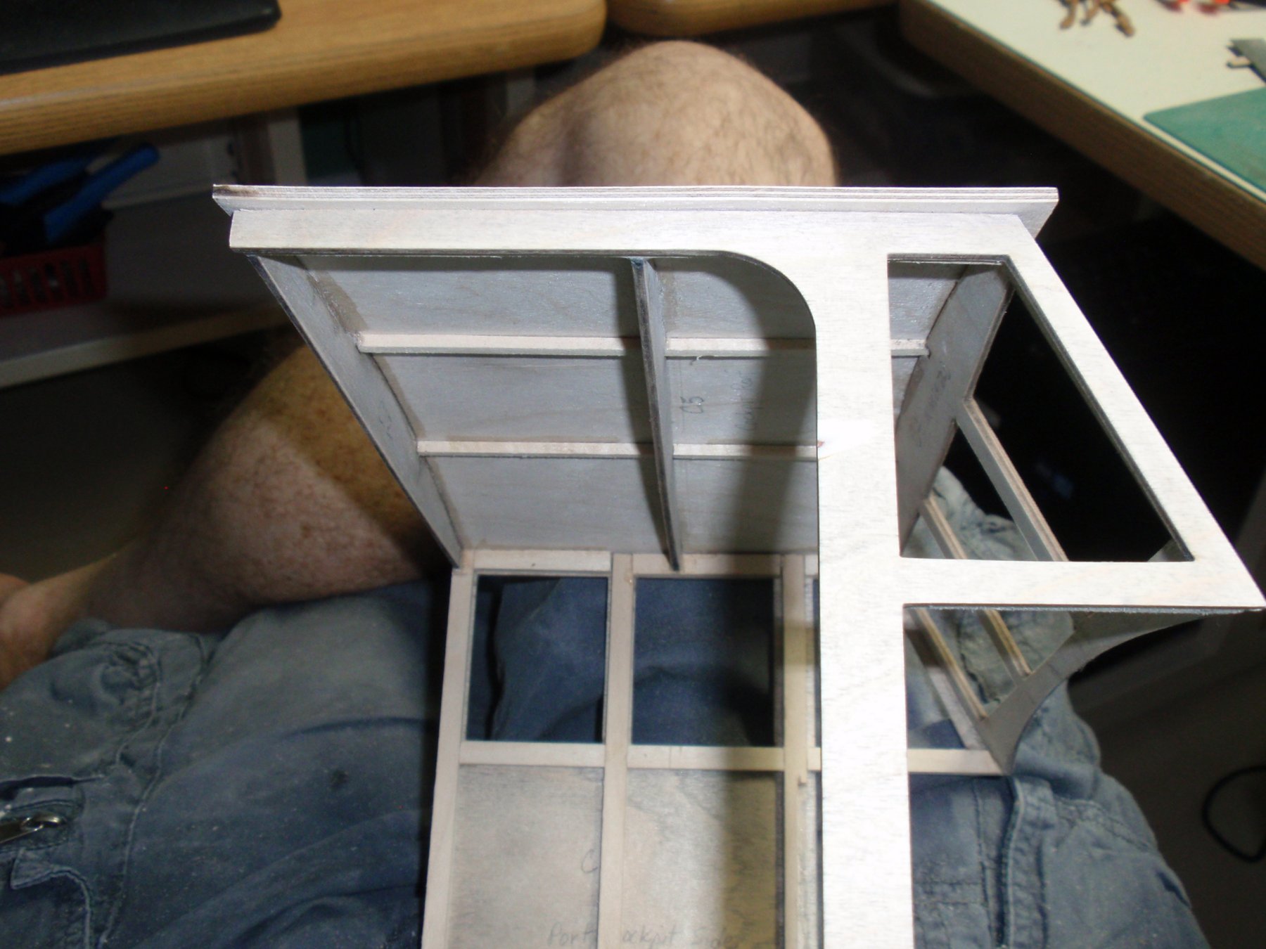
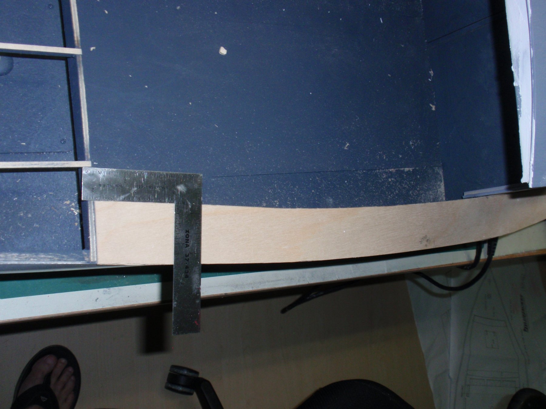
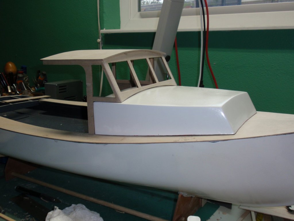
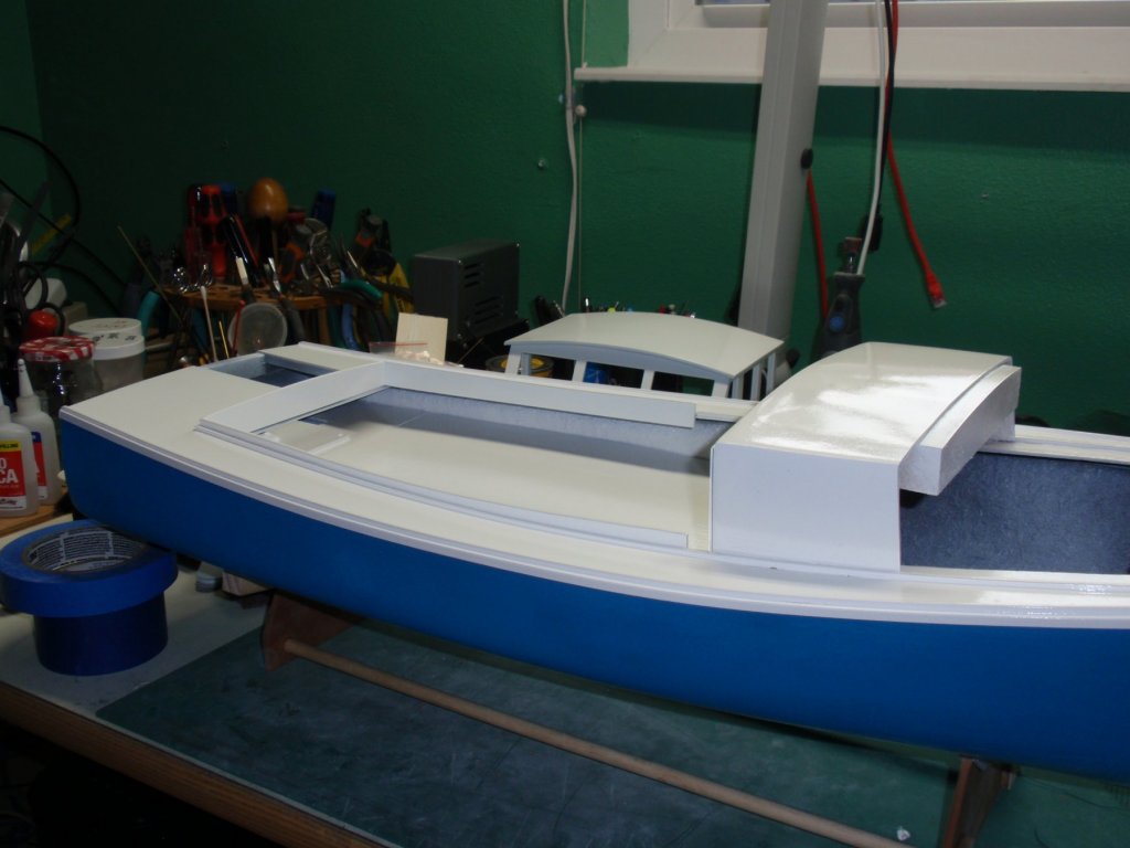
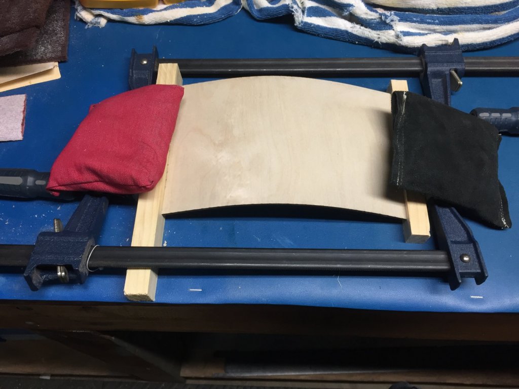
Installment #16 Cabin Roof and Sidewalls Work When fitting the cabin to the deck, it is important to have the cabin roof and surround structure assembled such that it can be temporarily placed in position for alignment purposes. The critical issue is mating the cabin roof to the deck while also aligning the roof and sides to the REAR of the fiberglass cabin. To get a good mating of the fiberglass cabin to the cockpit roof and sides requires some adjustments to the fiberglass cabin bottom and mating the curvature of the cabin fiberglass part to the deck. The other tricky part for this mating of fiberglass cabin to the windshield requires matching the windshield curve (at the bottom where it engages the fiberglass cabin roof) to the fiberglass cabin roof. I did not like the amount of trimming that would be required and thus decided to take very little material off the windshield bottom and correct for the remaining gap later. CAVEAT: The cabin roof cannot be easily warped and glued to the structure. The roof is thick material that resists warping. The sheet must be warped in advance to enable its attachment to the roof structure. The roof was soaked in warm water laced with some ammonia. Warm water alone may work just fine if you let it soak for several hours. Here are some images of the cabin roof, windshield, and sidewalls construction.


- 33 replies
-
- 2
-
-
- BlueJacket Shipcrafters
- Maine
- (and 3 more)
-
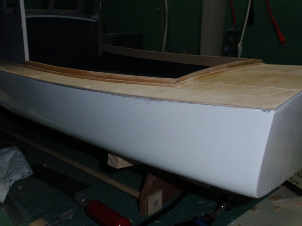
Installment #15 Decking/Coaming When fitting the decking, a lot of adjustments are necessary to match up with the various lines and curves. As indicated in a prior post, the rear-most portion of the deck was not retained in the deck sheets. It was removed to facilitate the deck installation. Using a square, the rear-most section was separated from the deck sheets at the point where the sheets intersect with the rear decking structure. Later, a separate sheet was used to cober the rear-most section of the deck. This worked rather well since the decking process and the precut shape of the deck sheets forces simultaneous resolution of a bunch of complex intersecting pieces. Here is another view of the rear deck area with the coamings installed and small square filler materials applied. You can also see the removable portion of the rear decking for access to the rudder assembly and servo in this picture.

- 33 replies
-
- 1
-
-
- BlueJacket Shipcrafters
- Maine
- (and 3 more)
-
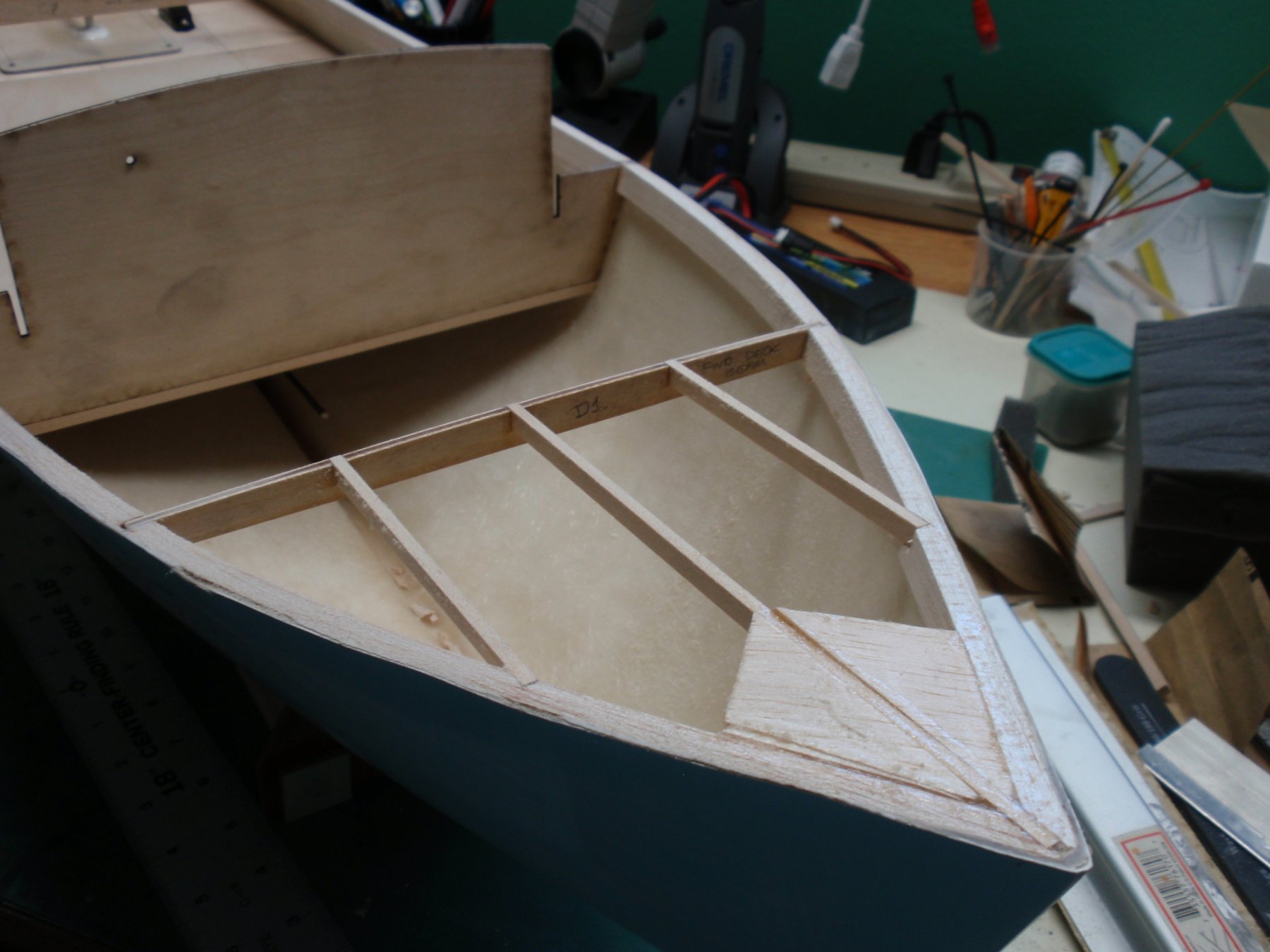
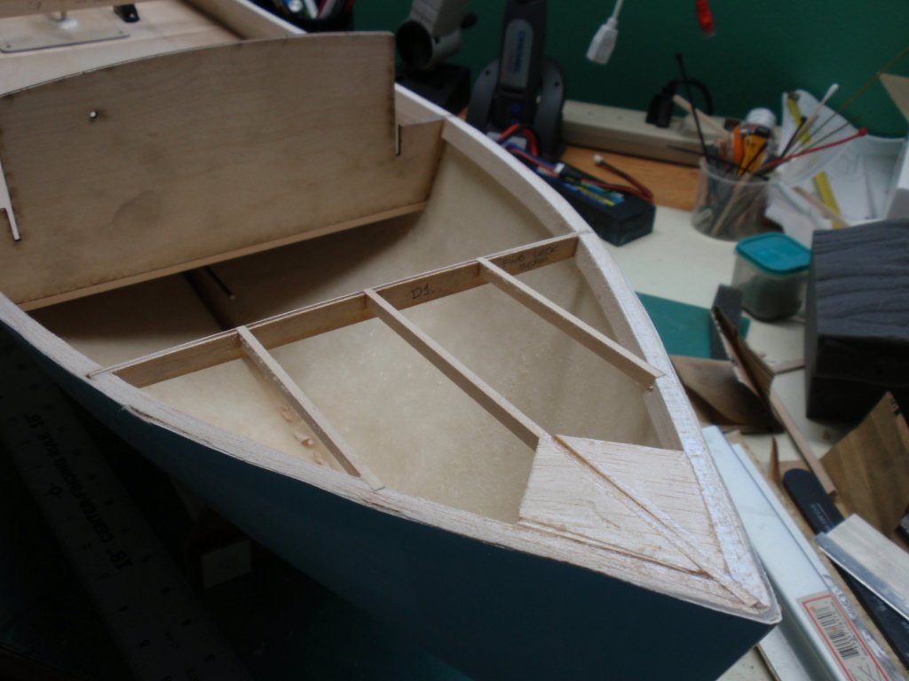
Installment #14 Preparing for Deck Installation The structure is built up using the instructions for the rear deck portion. This step is fairly straightforward. The fore-deck framing is built up. The details are well described in the instructions. I took some liberties with scrap filler materials at the peak.
- 33 replies
-
- 1
-
-
- BlueJacket Shipcrafters
- Maine
- (and 3 more)
-
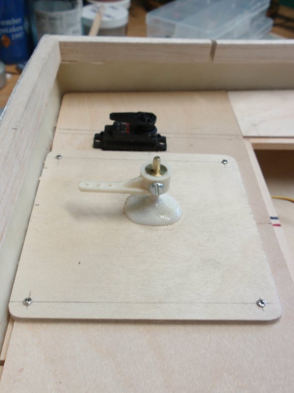
Installment #13 Well Deck Fitting - Rudder and Servo The kit-supplied rudder horn and user supplied servo are installed.
- 33 replies
-
- 2
-
-
- BlueJacket Shipcrafters
- Maine
- (and 3 more)
-
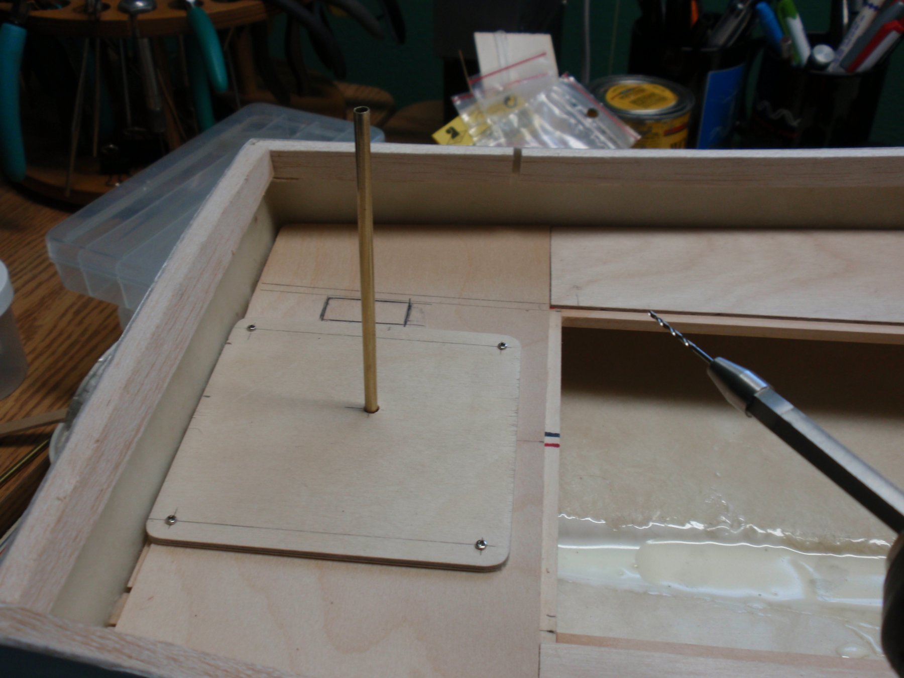
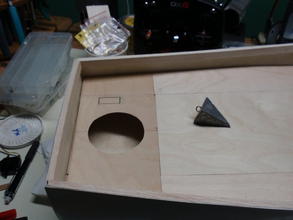
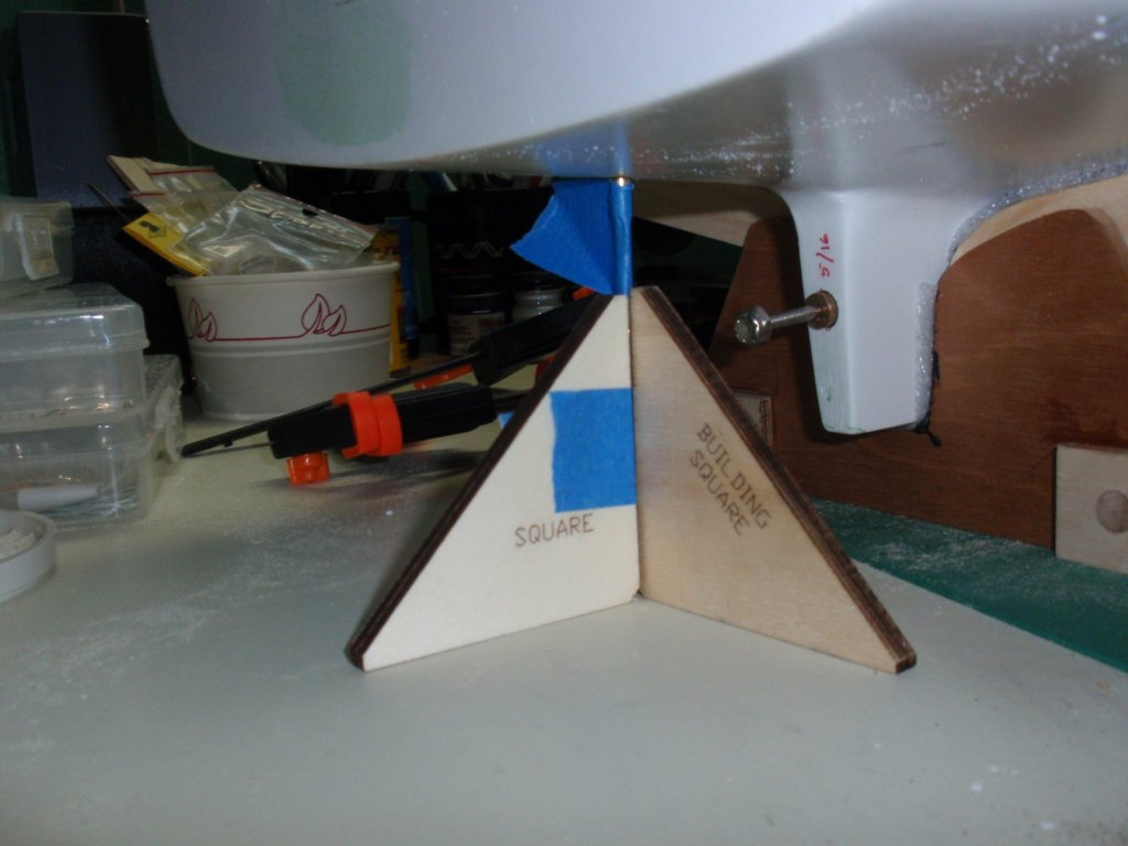
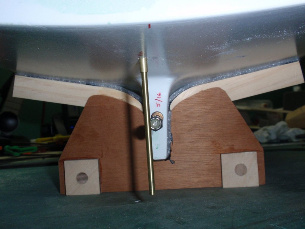
Installment #12 Well Deck Fitting - Continued 2 The following illustrates a hole cut for the purpose of installing a rudder that can be adjusted in angle relative to the stern, the hull bottom, and plumbed to the craft centerline (approximately.) You can observe the large hole for working in the bilge when locating and installing the rudder. Additionally, the outline of where the rudder servo is installed can be observed on the port side of center. The following images tell the story of how the rudder tube was located in thr hull and aligned. The image above illustrates a deliberate rudder offset that allows the propeller shaft to be removed without also removing the rudder. The shaft just clears the rudder assembly. Once the rudder shaft tube has been glued into place, a cover plate can be designed that covers the large construction hole and closes well deck. I used some really small wood screws to secure the cover plate.


- 33 replies
-
- 2
-
-
- BlueJacket Shipcrafters
- Maine
- (and 3 more)
-
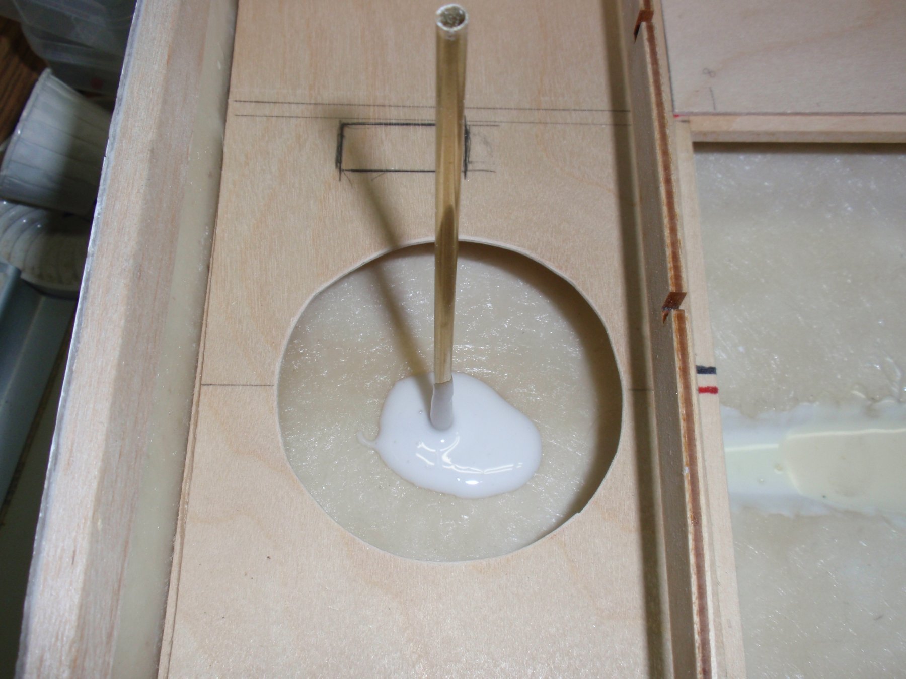
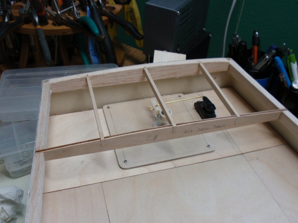
Installment #11 Well Deck Fitting - Continued The well deck was built up with some customized changes. 1. The well deck should have a removable floor access so that the internals can be accessed easily for maintenance and stowage of RC equipment. 2. The rear section must accommodate the rudder component installation as well as a servo for steerage. The following pictures illustrate the deck constructions complete with a removable access floor and a hole that is designed for aligning the rudder to vertical. In the image above the stuffing box and a significant portion of the bilge is exposed. The cross member that is exposed in the center of the well deck access hole is intended to assist in keeping the deck access hole cover sag free. The well deck with the access portion installed. Next, the rudder installation and alignment modification will be shown.

-
Greetings: Unfortunately, I have been unable to continue this build log due to an intervening medical issue. I am now ready to add more content. And now for the next installments...