


CiscoH
-
Posts
218 -
Joined
-
Last visited
Content Type
Profiles
Forums
Gallery
Events
Posts posted by CiscoH
-
-
do you know if Mr Tarjack is still building model ships? if its the same person he hasnt updated his royal caroline bone ship in several years
- Keith Black and mtaylor
-
 2
2
-
-
-
on my first ship i simply painted the brass black, which worked fine but felt like cheating. on my current build i spent a lot of time using various blackening chemicals which seem to wear off quickly with any manipulation. i think i may go back to paint. have you had a similar experience?
-
Thanks Thukydides. I am trying to get over this brasswork hump which I feel has slowed my enthusiasm and progress more than I'd like.
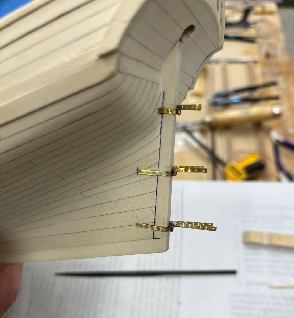
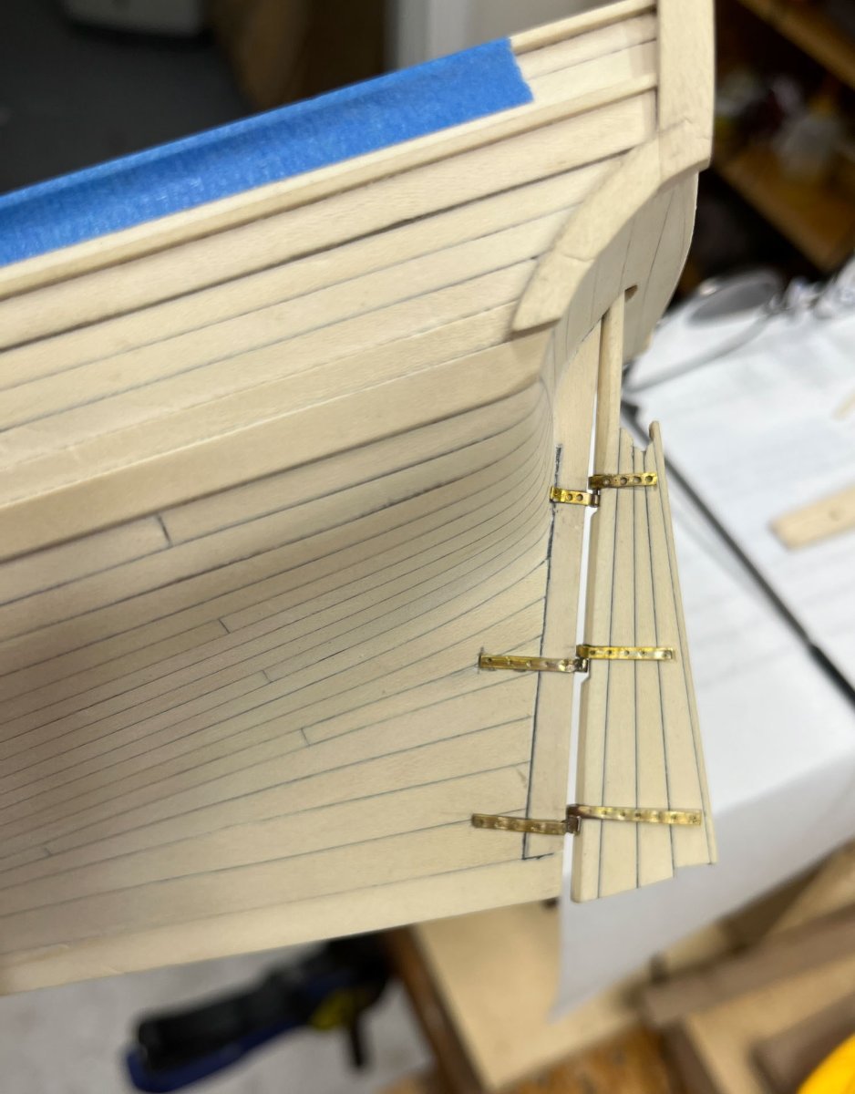
Probably because the pintles and gudgeons have taken way more work than I planned. This weekend I spent a couple hours fine-tuning. All the pieces fit mostly, but lots of slightly lengthening or widening mortises, slightly shortening and rounding off the ends of the strapwork, and chiseling holes to allow the rudder to be seated with the smallest gap possible. Heres where I started; to me the gap was too wide and the top pintle a little too high. Not much I can do about the high pintle at this point but I can work on the gap.

I also noticed all my handling and fitting of straps was getting the holly dirty.
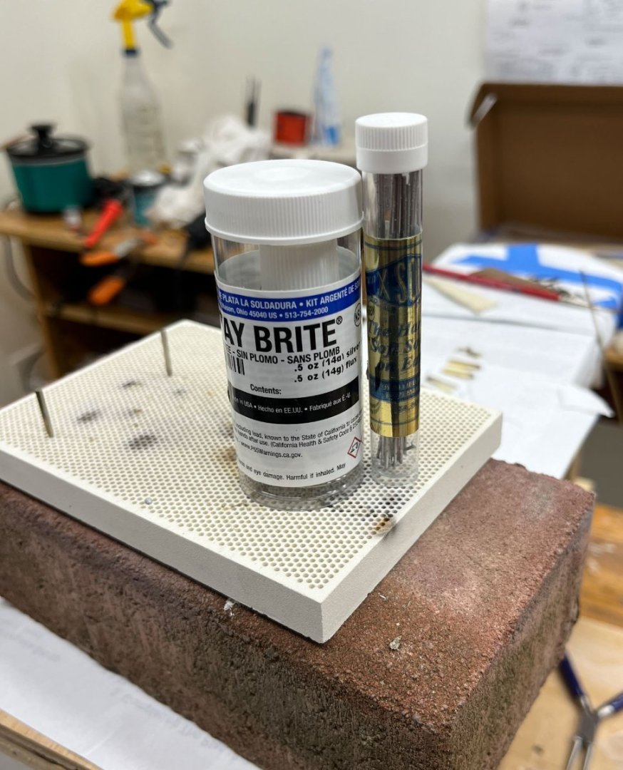
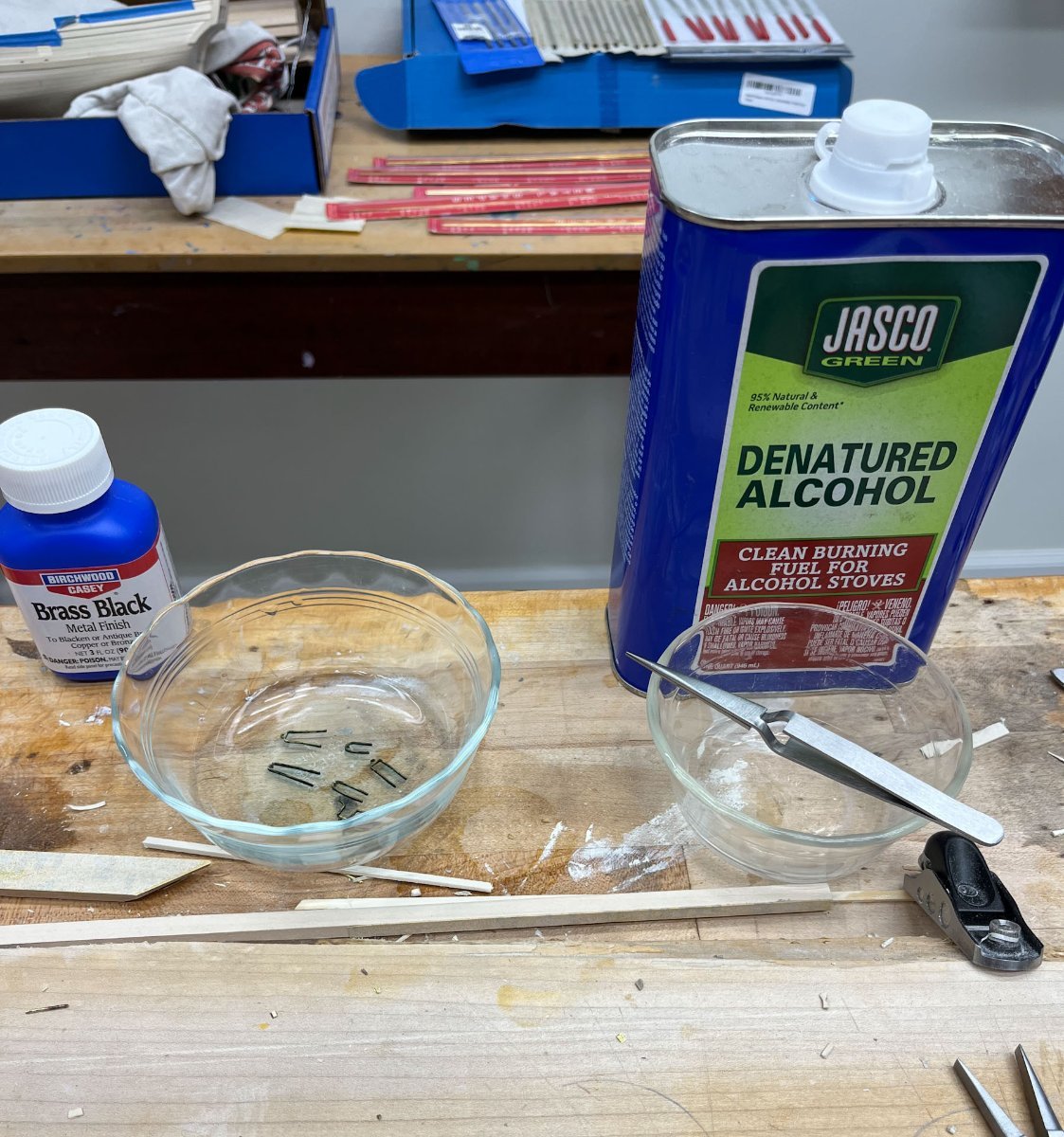
After this final futzing I washed the brass in isopropyl alcohol for 20 minutes, then moved them with stainless steel tweezers to a aprox 1:8 brass black to water for 15 minutes.
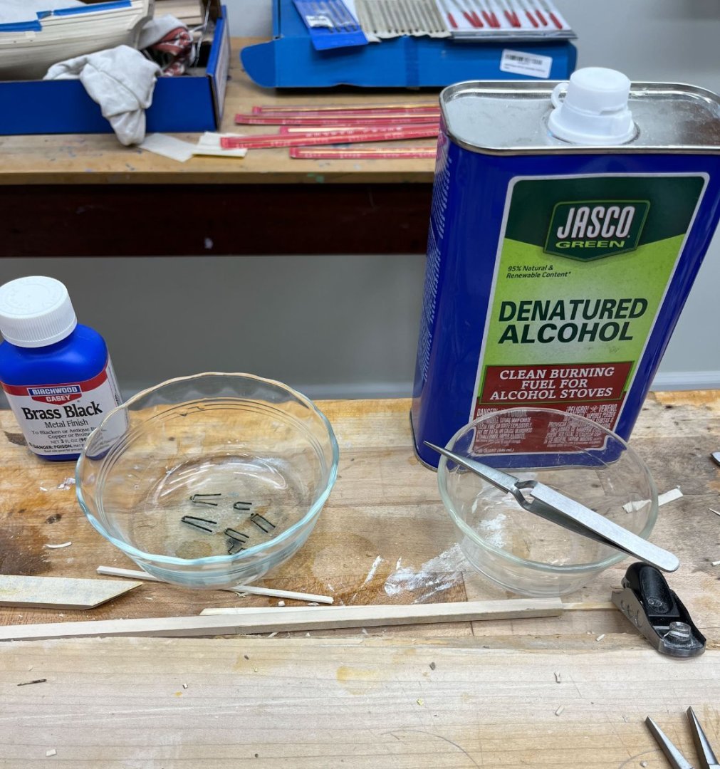
Here they are drying, about 99% coverage. 1 spot on a gudgeon that will need paint. I haven't handled them yet to make sure the blackening sticks but I am optimistic.
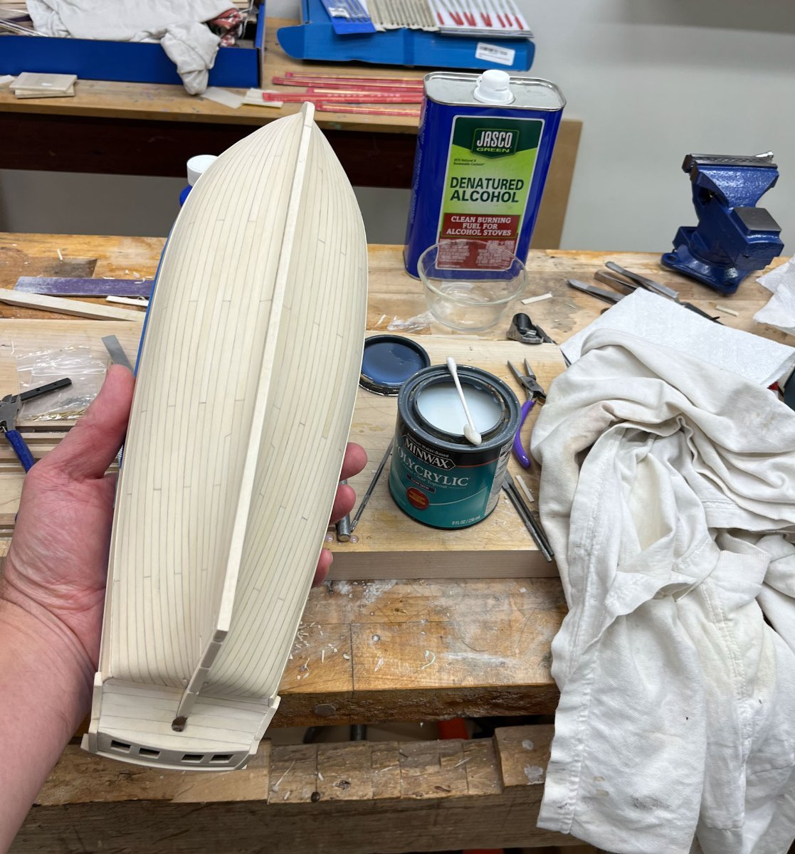
And finally I started with the hull's finish coat. After sanding off any marks on the sternpost from fitting the brasswork I applied the first coat of Polycrylic (water based polyurethane that doesn't yellow) with a qtip, the immediately wiped it down with a old cotton t-shirt. Most of the finish comes off so its a thin coat, but the tshirt smooths quite nicely. I'm guessing I'll do 3 or 4 coats. I have to test some of my discarded blackened brasswork to see if it looks ok covered with this finish; if not I'll put hinges in after finishing.
Here's the hull after its first coat. It looks almost identical to before I finished it, which is the point.

thats it for me. Monday is fast approaching and its off to mentally prepare with some hot chocolate and a book before bed.
thanks for reading
cisco
- whitejamest, David Lester, Chuck and 18 others
-
20
-
 1
1
-
-
i like the shape of the tombstone cutaways. very elegant
- Chuck, FrankWouts and Jack12477
-
3
-
-
-
Great evening fellow hobbyists. Time has not been my friend the last few weeks; work picked up and we took a week off for a Disney cruise, before the kids got too old to appreciate it. So this will be a short post, instead of my usual exhaustive run-on.
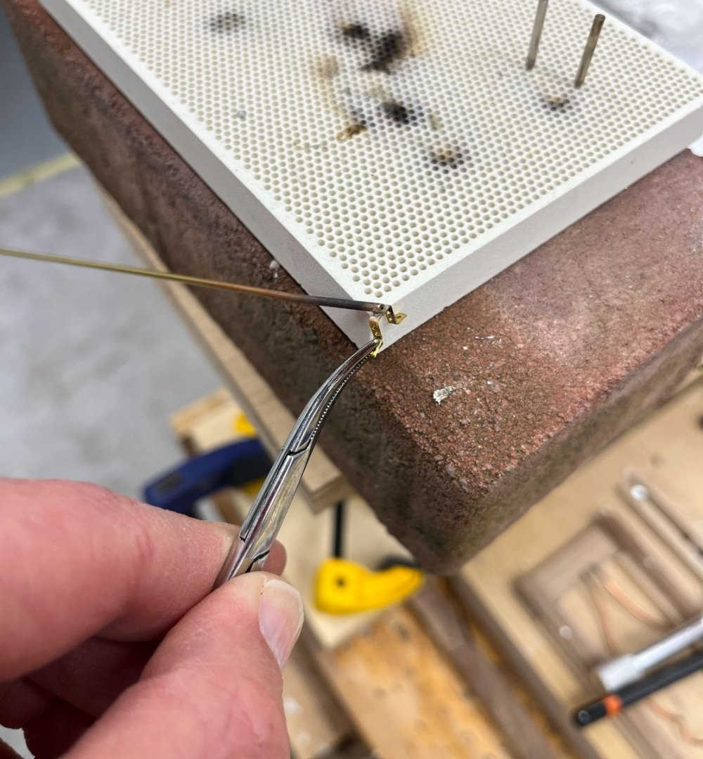
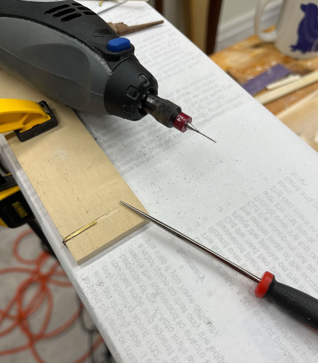
Last update I had silver soldered my pintles and gudgeons. I deliberately left the strapping too long so they could be trimmed to length to fit the shallow mortises on the hull and the rudder. As per my last update I found for me the easiest way to drill bolts holes was first cutting mortises into a scrap piece of wood to hold the hinges steady, dimple each spot with an awl, then drill with a Dremel.

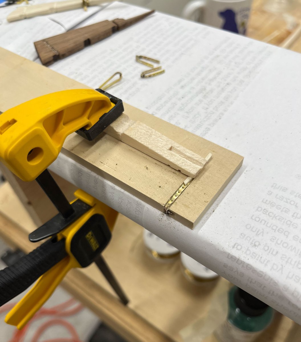
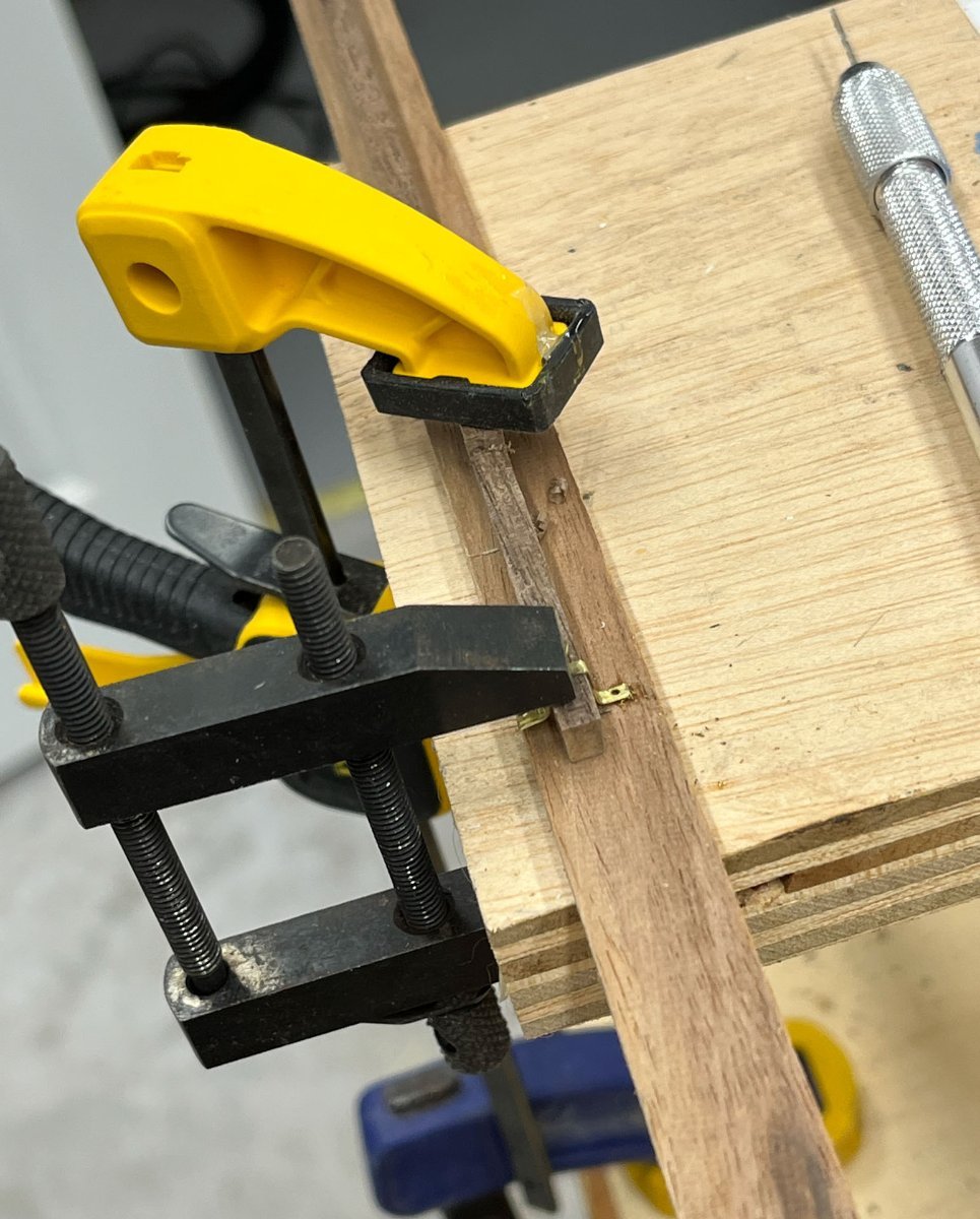
This worked well for the shorter hinges. I found on the above hinge, because the strap was so long it was very flexible, especially at the unsupported end. The second the drill bit went through the strap it would climb the bit and break it. That learning curve cost me my 74, 73, and 72 carbide bits. So I jury-rigged the below extra clamp (a tiny strip of wood held down with half a clothes pin) that worked to keep the strap in place.

I found I could widen the smaller holes with a regular wire drill bit so all are now 74 holes.
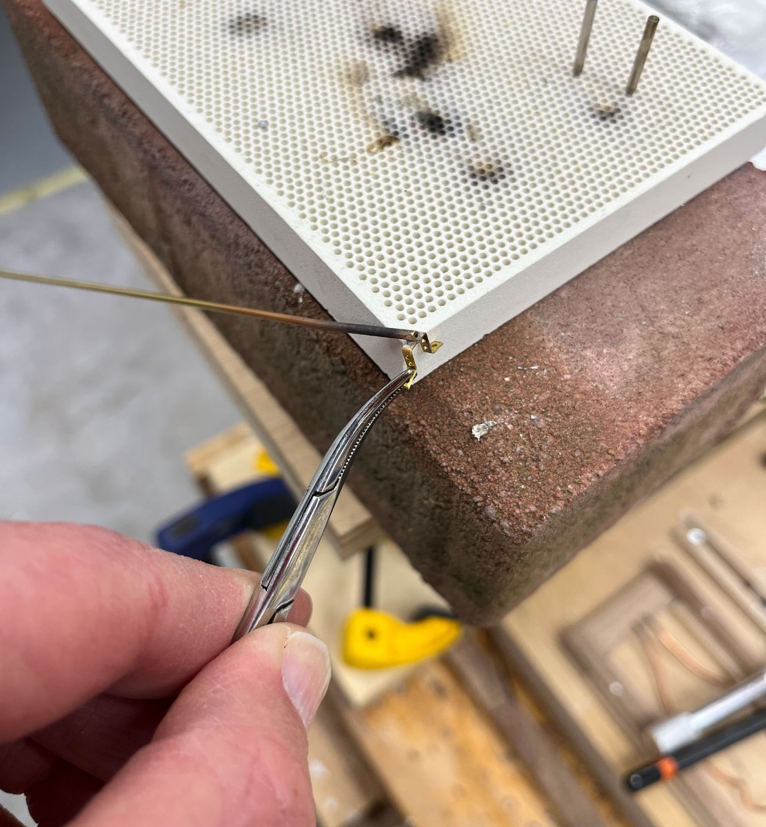
And here they are friction-fit on the stern.
Next up is flattening out the waves in the strapping, blackening, and installation with some clear epoxy. Afterwards I will put in the bolts. I have a feeling trying to hang the rudder and lining up those tiny pins will be challenging. I am thinking of trimming off the middle pintle pin to make life easier.
But thats next weeks problem.
thanks for reading
Cisco
- JLong, KurtH, JacquesCousteau and 4 others
-
7
-
I cant help with the counter as i havent built this ship but on my AVS model i had to sand a lot and add strips to shim out the bulwarks, just like youve been doing. the sweep up to the stern in your last picture is supposed to be sanded diagonally, a mirror image to the prow. Probly you know that.
i wonder if this design would have benefited from having an extra frame along the deck midline. then the bulwarks could have been “D” shaped instead of their S shape which always looked unstable to me.
but regardless great job i am following with interest; this ship is on my to do list
-
nice 3D effect on the tassels
-
-
-
Nice mitered returns on the deckhouse roof Dave
-
-
Good evening all. Its been a while. I spent a lot of time fighting with my pintles and gudgeons, mostly finding out how not to do it. My goal was to make a reasonable group of hinges, made of brass, fully chemically blackened (not painted like last time), with a minimal gap between sternpost and rudder, and with evenly spaced and in-scale bolts.
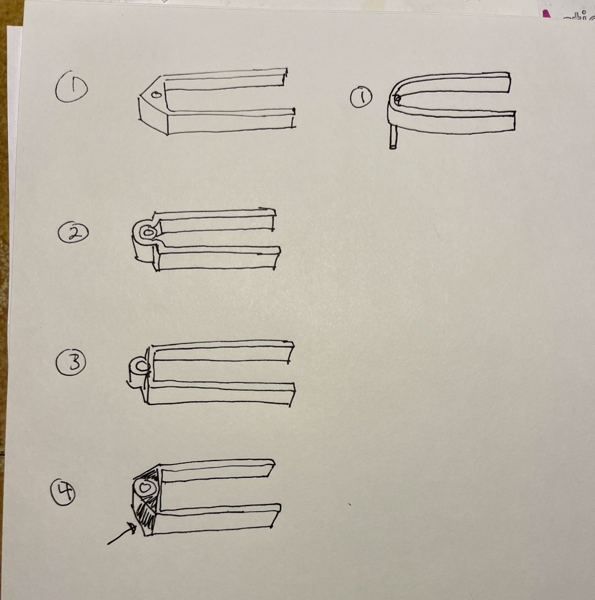
See the below cartoon. The pintle was straightforward; bend the brass strip in a gentle curve and silver solder a piece of brass wire in place, then trim. Worked well the first, second, and third times. Also backened perfectly.
The gudgeons, however, fought me every step of the way.
I originally went for option #2, bending the brass strip around the outside of the brass tubing and silver soldering it in place. But (see last post) this led to too much of a gap between the stern post and rudder. It was also very challenging to make correctly spaced bends to fit around the sternpost. I ended up fatiguing the brass strip bending and rebending until unsurprisingly one side broke off. I decided this was not working well and looked for better options.
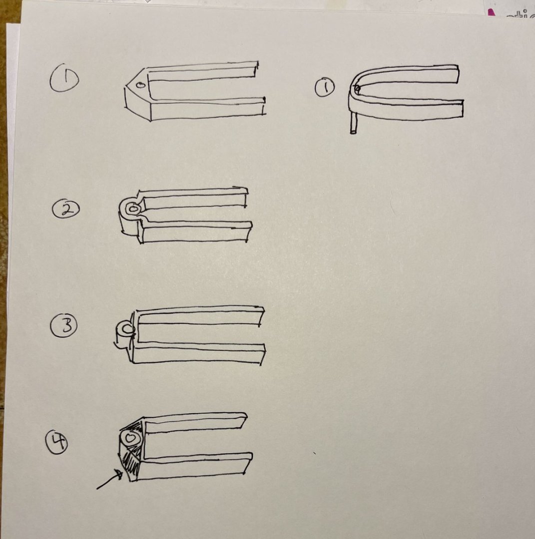
After some MSW scrolling I decided what I really wanted was something like option #1, with a triangular "head." I pre-bent the brass strip and silver soldered the tube on, just like in #3 above, without trouble. You have to be careful the tube is centered on the strip, and not crooked, but overall not too hard. I went with silver solder because the bond is so strong, but silver solder doesn't fill gaps.
Figuring How Hard Could it Be, I tried to fill in the space between the tubing and brass strip with lower temp solder, in effect changing #3 into #4 above.
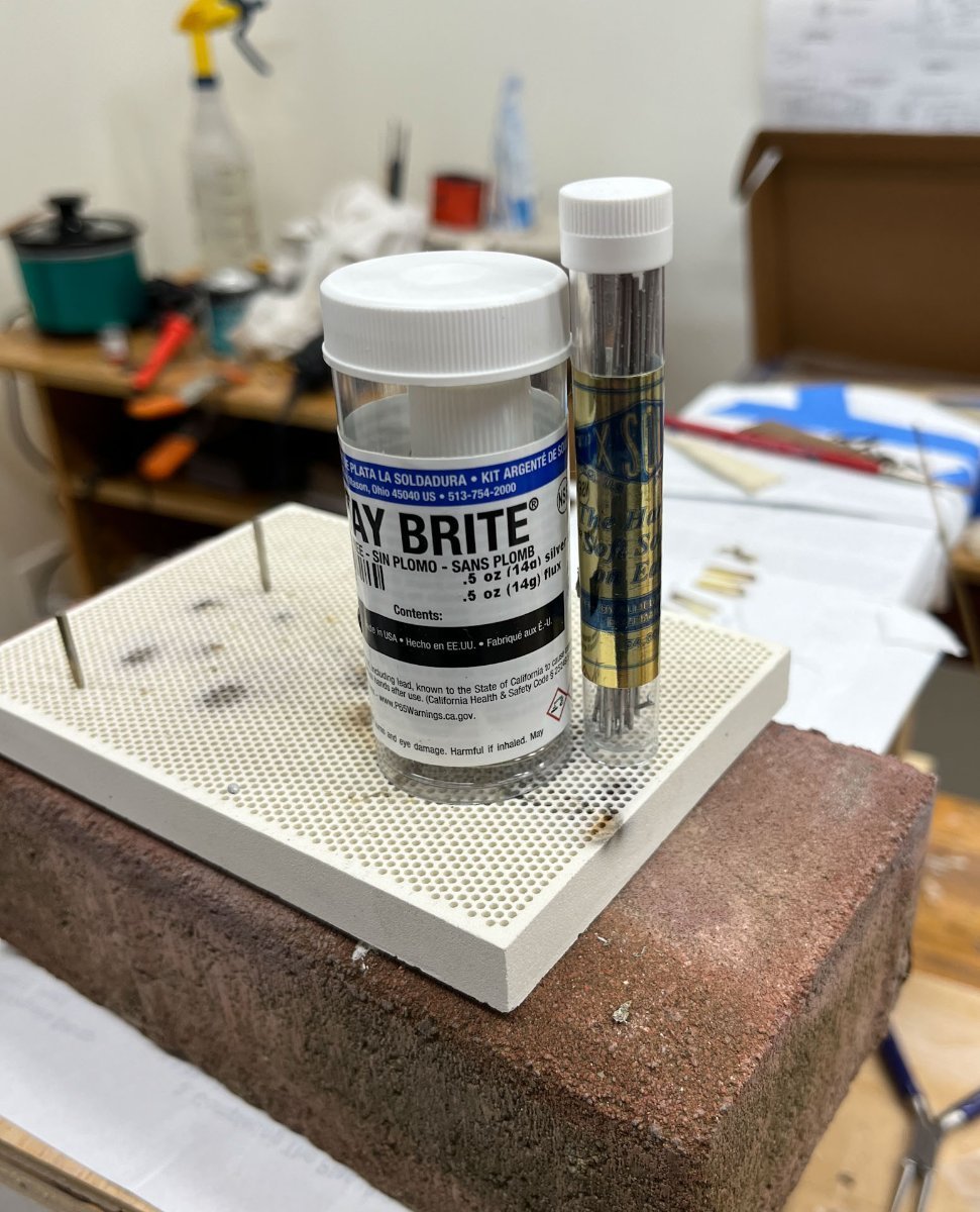
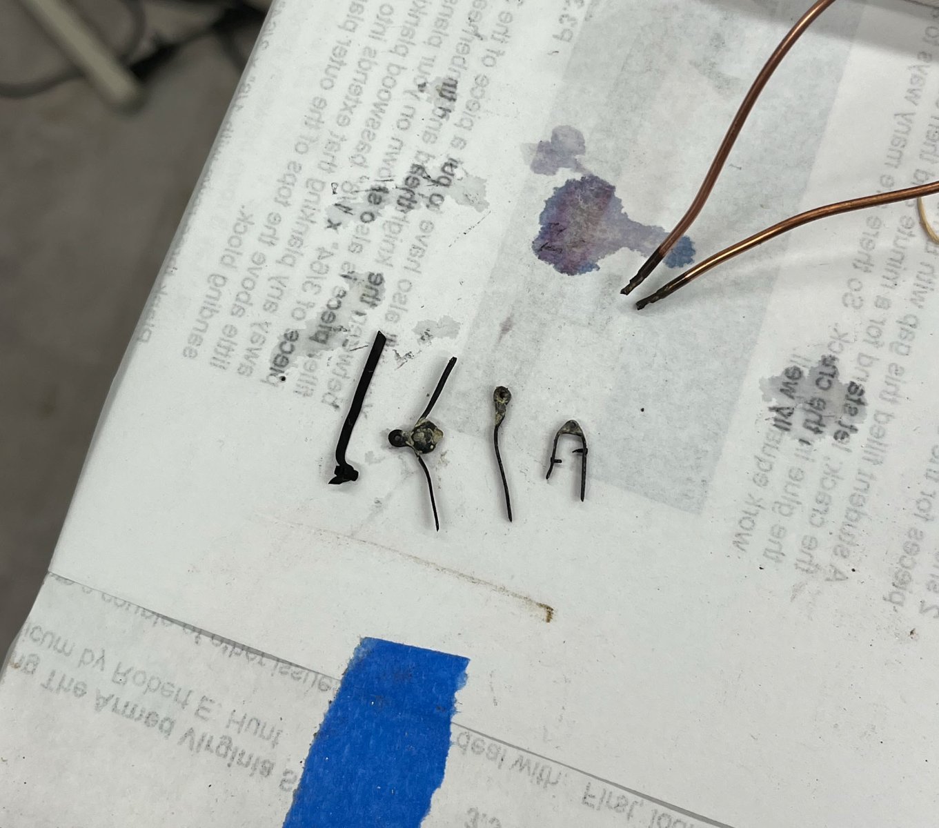
I cleaned the gudgeon in isopropyl alcohol, wiped on flux, then touched a 40 watt soldering iron to one side of the hinge while touching the strip of solder to the opposite side. This was challenging; the solder wanted to go anywhere except where I wanted, and as I had to do each "corner" separately I tended to melt my previous efforts. But eventually I got a test piece with good blobs of filling solder which I filed down until it was the triangular shape I wanted. So a lot of work but getting there. That piece is in the far right of the picture below. On this piece I also practiced drilling some bolt holes and made some improbably small bolts.
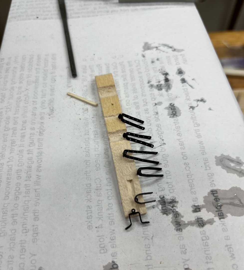
Then I tried blackening and things went downhill. Below you can see my test pieces. The one of the left is my original effort with one broken wing (#2 in my cartoon) and only silver solder. It blackened perfectly. The 3 pieces on the right all have low temp solder (either Tix or StayBrite) on top of a silver soldered joint. Anything I touched with the low temp solders wouldn't blacken; often even in areas on the brass strip that I didn't directly solder. For blacking I used Blacken-it for the first test, and Greg's (DVM27) sparex/Jax black procedure for another. Neither worked; the soft solder turned a flakey grey and the black that did form could be easily rubbed off.

This had been a lot of work leading to a dead end and it took me some time to get my enthusiasm back.
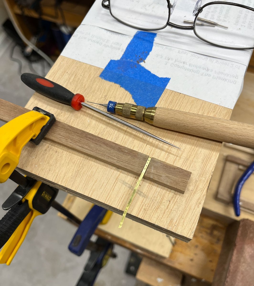
To change gears I decided to find the best way to drill the bolt holes. I don't have a milling machine so it was all by hand. Before I used my dremel, which went quickly but the bits liked to skate, leading to unevenly spaced holes. So I tried it manually. I got an awl and dimpled the brass strip, then used a 75 carbide drill bit chucked into a wooden handle. It quickly became apparent this wouldn't work; I got nicely spaced holes but broke 3 bits for 4 holes. The slightest lateral pressure and the bit would snap. The Dremel, I think, rotates fast enough that its harder to bend and break the bits.

Below I tried dimpling the brass strip and drilling with a "normal" wire drill bit. But the bits were worse to keep centered, went dull after 1 - 2 holes, and then refused to cut. No go.

Eventually I went back to dimpling with the awl, then drilling with the dremel while periodically dipping the tip of the carbide bits in some 3-in-1 oil, which made them cut much better. The holes were not perfectly spaced but probably good enough. I suspect you won't be able to see the bolts (matt black bolt heads on a matt black strip; basically invisible).
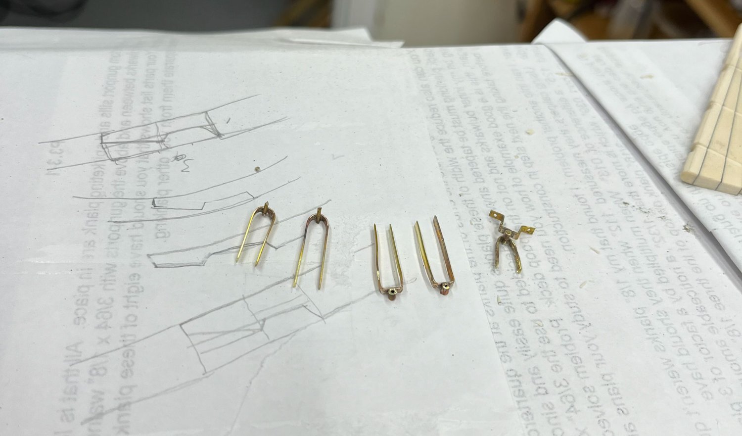
So now, having spent weeks chasing my tail, I finally have a plan. I am making the gudgeons simple, #3 in my above cartoon, just brass strip with a tube. These reliably blacken, are very strong, and don't stick out too far.
My next trial run with the top hinge. In this case I drilled all the bolt holes before soldering, but for the other 2 hinges I plan to drill the holes afterwards.
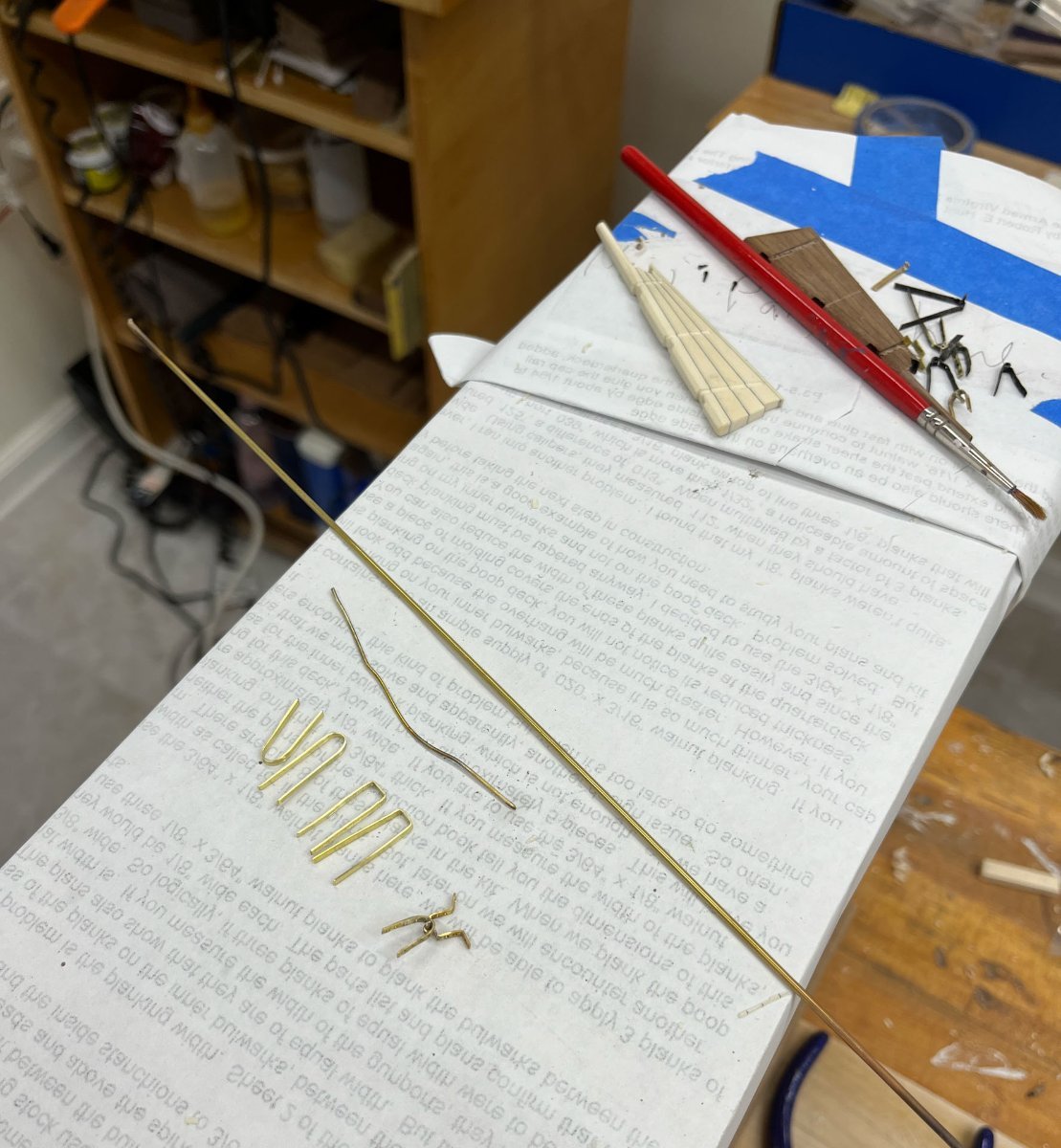
This top hinge wet well (bottom right below) and so I spent tonight making the other 2 sets. First I bent the brass strip to the correct dimensions, testing in situ on the rudder and the stern. Its very easy to make them too big or small.
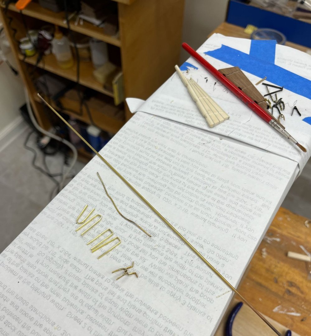
Then silver soldered the pins and tubing.

Next is drilling all the bolt holes. Then gluing the hinges in place with epoxy, afterwards adding the bolts. I bet anyone who made it this far in this post is done with pintles and gudgeons; I know I'm ready to move on.
Have a great evening, thanks for reading.
Cisco
- JLong, Thukydides, Dave_E and 11 others
-
14
-
-
I agree the grain is better (much less obvious) with the pear. Beautiful panels and the hardware looks to be in perfect scale. If I may add a subtle critique, and I understand this is a test piece and maybe you already know this, usually the bottom stile of the door is wider than the middle and top ones (see the dashed line in the plans on your post #82 which shows this). The same goes for the bottom stile of the curved side panels, which in the plans are level with the door bottom stiles so its a nice horizontal gentle curve following the deck camber.
But I nitpick. No offense to anyone who feels otherwise but to me laser-etched panels and doors stand out because they dont look real; I feel your test piece is way above the pre-fab kit parts.
-
-
-
looks great! i’ve personally always preferred the look of cannons/carronades when they are tied up for travel, whatever thats called, like you did here, as opposed to having the ropes coiled up on the deck.
-
-
hope you can re-use some of the planks Kortes
- FriedClams, mtaylor, scrubbyj427 and 1 other
-
4


The Flying Dutchman by BLACK VIKING - first scratch build
in - Build logs for subjects built 1501 - 1750
Posted
better and better! amazing job