


tmj
-
Posts
271 -
Joined
-
Last visited
Content Type
Profiles
Forums
Gallery
Events
Posts posted by tmj
-
-
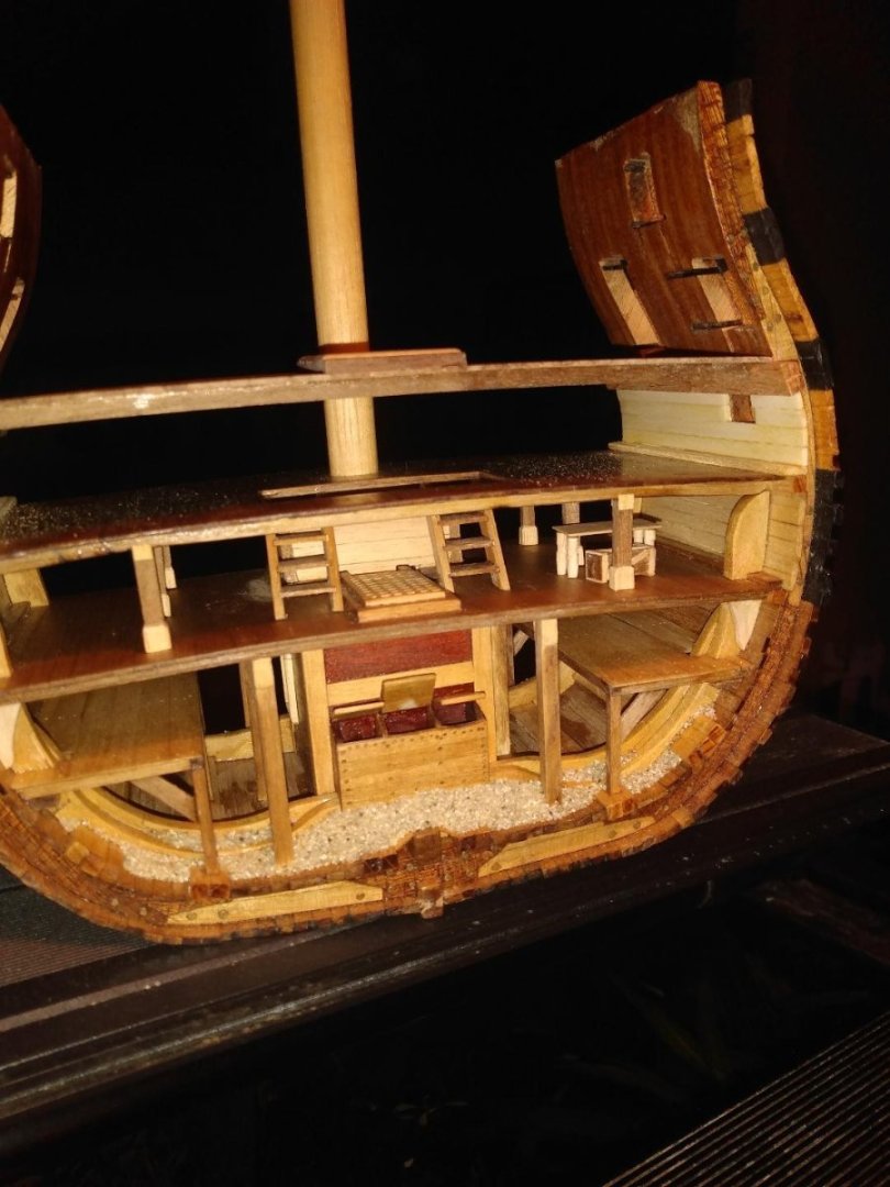
I finally got around to building a table and a crate for the Orlop deck. I'll probably make one more of each for the port side of the deck.
-
Thanks Mark. Unfortunately, the ship in question is the Continental Frigate 'Hancock' (captured) aka the 'Iris'. There doesn't seem to be much data out there, for this vessel, other than RMG's plans.
- thibaultron and mtaylor
-
 2
2
-
If the 'Body Plan' offers the exterior geometry of the stations, how does one go about acquiring the 'interior' geometry for those stations? I know that this is a really basic thing for you experienced folks, but I'm stumped!
- mtaylor and thibaultron
-
2
-
3 hours ago, Gregory said:
I'll have to dig into it if it does..
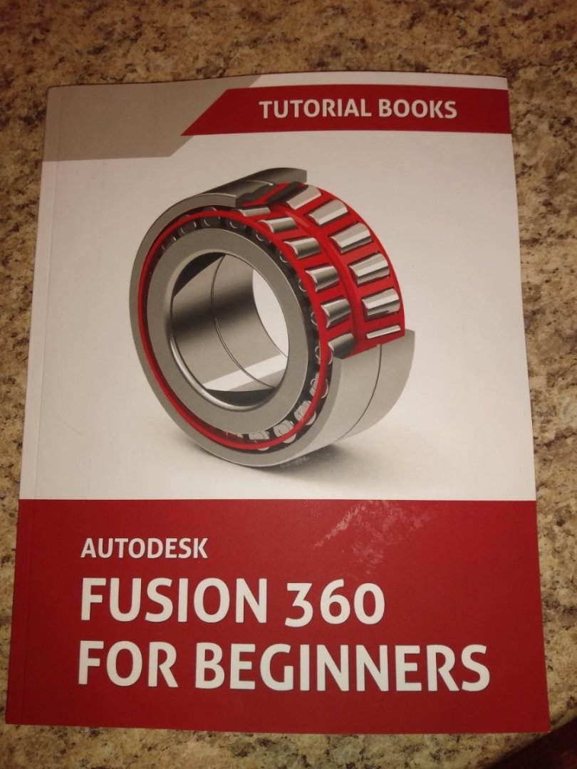
Autodesk offers a free version for personal, noncommercial use.
- Nirvana, mtaylor and thibaultron
-
3
-
2 hours ago, Gregory said:
Here's a nice demo with Vcarve
High Gregory!
I watched that video back when I was first shopping for my router. It's a good video, however. I'm going to stick with Fusion 360 for the CAM end of things. Fusion 360 will do everything the other CAD/CAM software packages can do. I might even transition over to doing all my 3D modeling in Fusion as well. I just need to go through the ol' learning curve as Fusion 360 does not work quite like AutoCAD.
- thibaultron and mtaylor
-
2
-
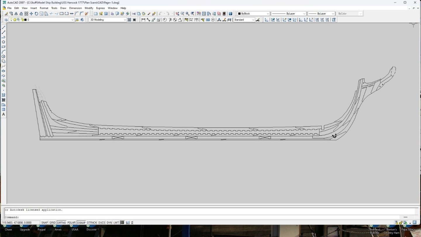
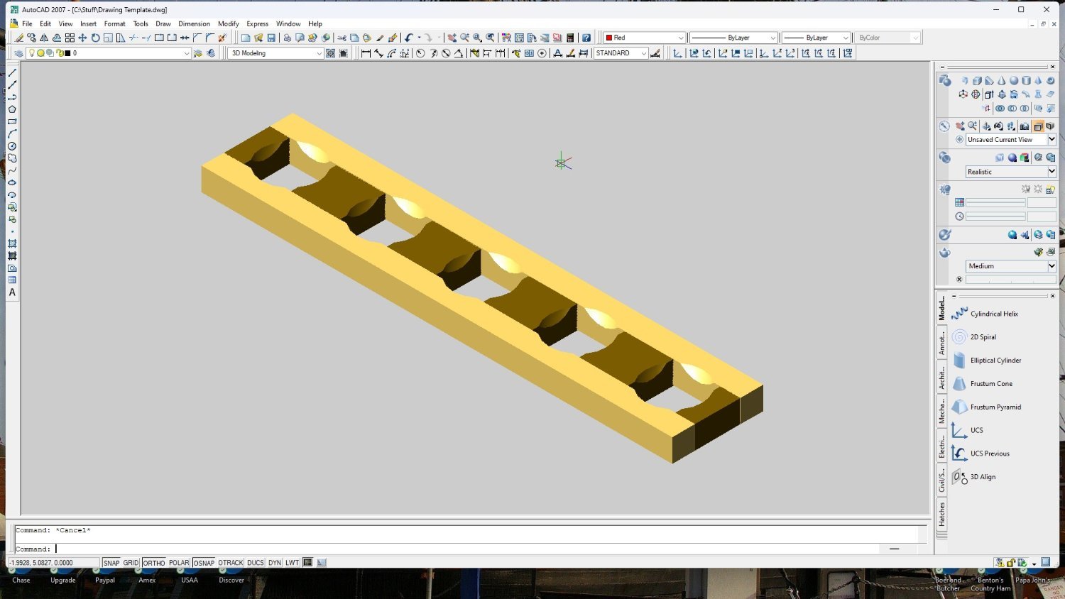
I'm still struggling to figure out just how Fusion 360 works. My knowledge of traditional AutoCad doesn't seem to apply... and watching Youtube videos isn't proving to be of much help either. I guess I'm just going to have to 'bite the bullet', turn in my "Man-Card" and actually resort to reluctantly reading the written instructions! *sigh*
- mtaylor, thibaultron and Nirvana
-
2
-
 1
1
-
On 10/31/2023 at 5:42 AM, allanyed said:
Hard to tell based on the photos, but do you have the battens running fore and aft as they always did with the ledges running athwartships?
No Allan. I have them backwards, "of course!" Another newbie lesson learned! 💩 That's okay. This is just a training model. I need to make as many mistakes as possible on this build in hopes of 'kinda' knowing what I'm doing when I start my next build. Thanks for pointing this out. This is another one of those 'little' things that I'd have never thought would have a right way and a wrong way!
-
On 9/10/2023 at 3:03 PM, Bob Cleek said:
I'm sorry I don't have any more specific information on this, but I recall once reading somewhere that of the several species of bamboo, some are better suited structurally for use as trunnels because they draw to size more cooperatively than others. Somebody reading this may know more and share with us the right species of bamboo to use and where it might be sourced.
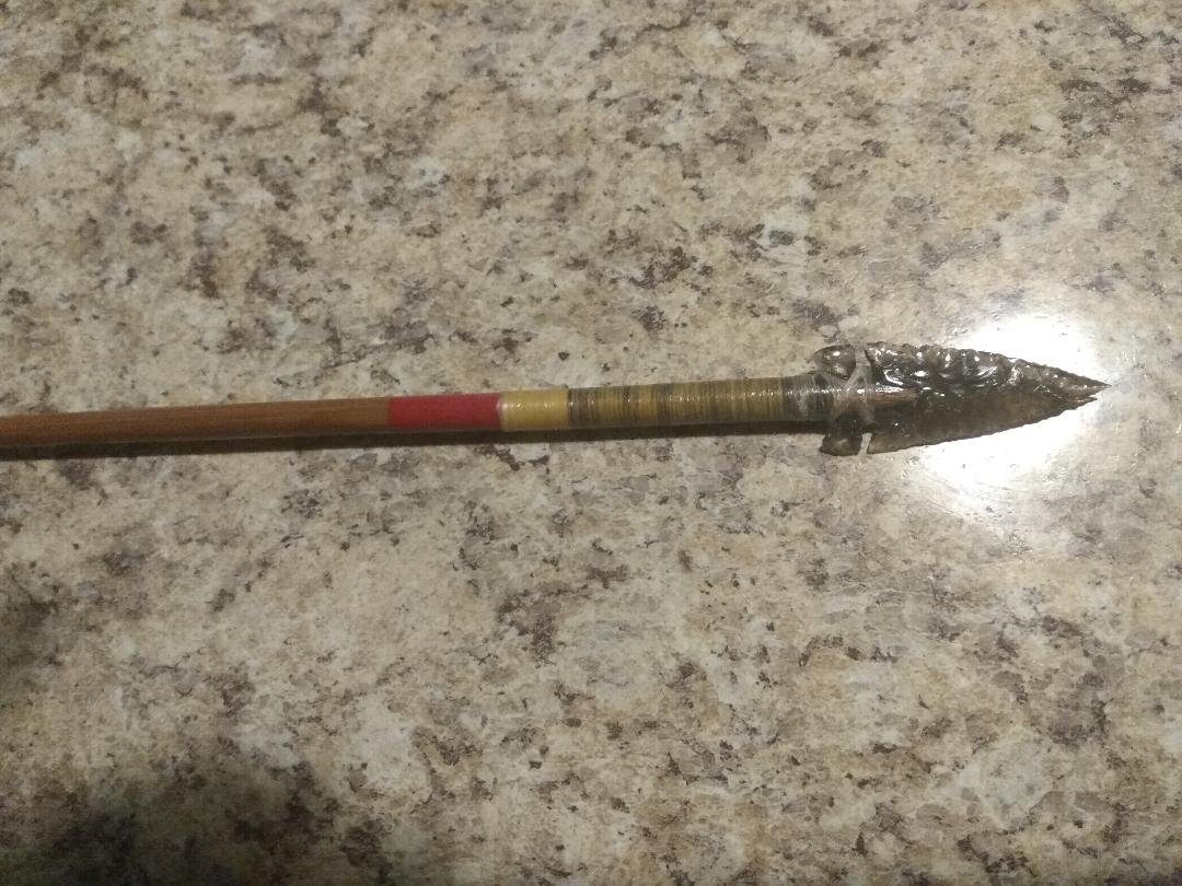
I used to mess around with primitive archery, bow building, flint knapping and building arrows that were 'spined' in the 70–100-pound range. I used bamboo shafts purchased on eBay, directly from China. They always worked very well and are very tough. I wonder if bamboo intended for arrows would be a good choice for drawing through a plate in small diameters. I still have quite a few unused shafts. I'm going to give this a try, however. I don't yet have a drawplate. Speaking of such. Does anyone know if Jim Byrnes is ever 'really' going to open up for business again???
Below is a bamboo arrow spined for a 90-pound bow. I've never shot this arrow due to the obsidian point, but all of my field points flew really well on the bamboo shafts. I just wanted to show this arrow off. It's the best obsidian point that I ever knapped. 🙂
-
1 hour ago, Bob Cleek said:
No need for apologies. I find the same frustration with the search engine myself. (Sometimes opening up another window and "googling" a topic is actually an easier way to find it in the MSW forum!) In this instance, "horseshoe" was an easy one to search. Google would have yielded twenty-six "sponsored" advertisements for horseshoes and local farriers, I'm sure!
What I'd like to know about these "horseshoes" used to reinforce scarf joints is why they were horseshoe-shaped. It seems to my "armchair shipwright's" mind that a squared flat plate would serve as well and be a lot easier to fabricate and install. I wonder if the shipsmiths actually just hammered flat old worn-out horseshoes to fashion these and didn't bother to take the time to forge straight, flat stock. Some of the horseshoe-shaped reinforcing plates are quite large, but draft horse hooves are quite large and there were a lot more draft horses around in those days than now. It just doesn't seem like the shape has anything to do with the strength of the fitting.
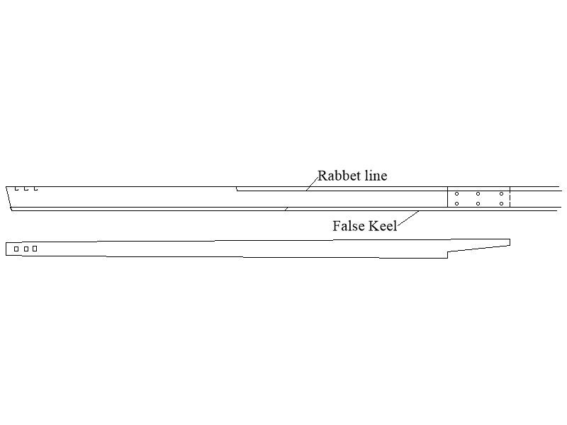
I agree with the shape thing, but not so sure about the size. When looking at the construction methods of the 'Essex', I'd say that the horseshoe shaped 'plate' was quite large... larger than any horse hoof. Yes, I'm curious too. I don't understand the shape. There would definitely be far better plate designs than that! Maybe the old-world builders were just superstitious and simply wanted the inverted horseshoe shape to trap and hold good luck! 🙃 As for the size? The below image is of the 'Essex's' stem, stern and keel. I'm using the Essex to model the construction methods of the 'Hancock'. If the resource I'm using is correct (32 Gun Frigate 'Essex', anatomy of the ship, by Portiat Takakjian) that horseshoe would fit a horse of 'mythical' proportions! Hopefully, someone with more knowledge will be able to chime in and clear up some of the odd-looking details and curious questions. I'll certainly be interested in this as my Hancock build will only be planked from the waterline up. All construction details 'below' the waterline will be exposed.
-
14 minutes ago, Bob Cleek said:
The "search" thingy is our friend!
Sorry Bob. I sometimes use the search box, but most times I do not. I've grown accustomed to finding everything under the sun 'except' for what I'm truly looking for when I use the forum's search option. It's usually easier and faster to ask a question and get a response like this. 🙂
-
Were 'horseshoe' plates, on early American warships, bolted to the exterior of the lower stem timbers, or possibly 'inlayed' flush to the outside of those timbers to keep things streamlined in the water?
-
-
-
-
-
I'm trying to find the approximate diameters of the cannon shot that would be found on all three of HMS Victory's gun decks. I keep finding 'poundage' ratings for the shot, but no actual diameters. I'm searching for the diameters of the shot(s) in order to determine whether or not I can feasibly fabricate scale replicas of the type of shot garland 'construction' presented by Morgan, earlier in this thread. Who here knows what the diameter of what HMS Victory's different size shots would have been?
-
I just took a peek at a plan view showing the top of the keel, just to make sure that I did not miss anything. No joints at all are shown on the top/plan view of 'that' drawing of the keel. "It's amazing the stories that can be told with more than one view and the understanding of a 'symbol'! 🙂
-
2 minutes ago, allanyed said:
The below may help showing aft section of keel with starboard side view and top view.
Allan
Allan,
'That' answers the question! Thank you for the plan view and an elevation view! It makes sense now. I've never seen any hidden lines in the drawings that I have looked at. I only see a solid rectangle with an 'X' going from corner to corner. That 'X' does not belong in a mechanical drawing depicting a joint like this, not for true construction. This tells me that the rectangle with an 'X' 'is' just a symbol! I also now understand why such a joint is called a 'vertical' scarf joint! Thank you!
Would this joint have been tree-nailed, bolted, or bolted like a sandwich with metal plates being on the port and starboard sides of the joint?
-
-
10 minutes ago, mtaylor said:
TMJ.
Get a copy of Historic Ship Models by xu Mondfeld. The most inexpensive place is Ebay though Amazon might also be a good source. It has a good breadkown of the various bits and pieces of period sailing ships. There are some errors but one can follow up with a Google search if something seems "off".
Thanks Mark. I found a copy on eBay for cheap. It's on its way.
- AJohnson, mtaylor and thibaultron
-
3
-
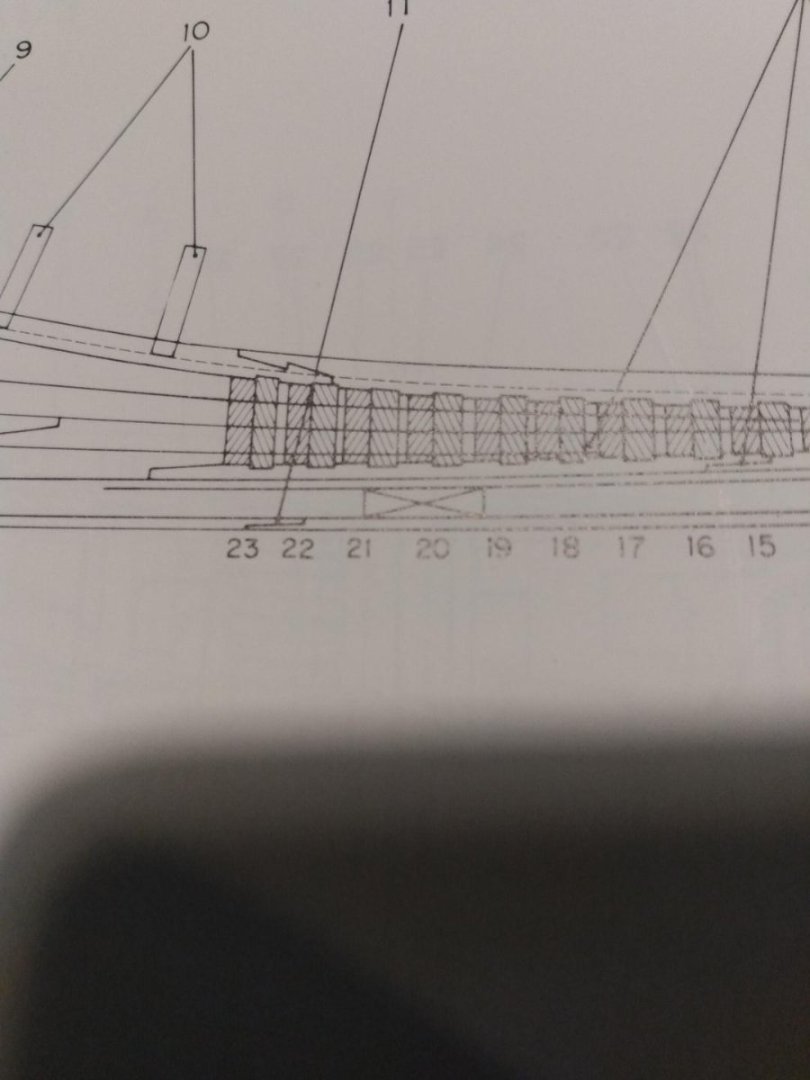
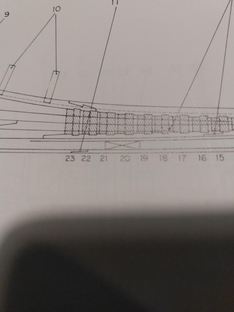
I keep seeing scarf joints shown on keels, as depicted in the photo below. This rectangular box with an 'X' in it confuses me. Does this symbol mean that the scarf joint could go in either direction, from stem to stern, or vice versa at the builder's discretion? An explanation of what that symbol actually means would be greatly appreciated!
-
17 minutes ago, Morgan said:“Before 1780 shot racks were placed against the sides of the ship. By an order of 27 May 1780 they were directed to be moved to amidships or round the hatchways if desired, and these continued to be their positions till long after 1800’s. On 29 Mar. 1803, when the Victory was completing her repair, the Navy Board wrote to the Admiralty: "Understanding that it is now the practice on board H.M. Ships to keep the shot in the match tubs and put them in grummets [shot racks / garlands] upon the deck; if this circumstance is known to their Lord- ships we are desirous of being informed whether we shall continue to fit shot racks round the coamings of the hatchways, as it appears to us to be an unnecessary work and employing men improperly if they are to be removed by the officers." The Admiralty answered two days later that shot racks were to be fitted in the usual way except upon the quarter deck.The Victory therefore must have had shot racks round the hatchways on all decks except the quarter deck“.
Gary, the depth of your knowledge and your case 'proof's' never cease to amaze me! "Very enlightening and 'always' welcome!"
- mtaylor, AJohnson and thibaultron
-
3
-
2 minutes ago, allanyed said:
One example is below
Ahh, okay, I get it now. Thanks Allan! Someday I'll become more familiar with a lot of these old naval architectural terms, but for now... you guys just need to bear with me! Sometimes I feel like 'Curly' from the 3 Stooges. "I'm trying to think, but nothing happens!" 😶
- thibaultron, allanyed, mtaylor and 1 other
-
4
-
I used to use contact cement to bond balsa wood sheeting to foam core wings back when I raced R/C pylons (quickie races). The contact cement worked 'great', however. These airplanes also didn't have a very long lifespan. They were cheap, fast, disposable airplanes! I still have two elderly 'Scat-Cats', standby leftovers from my racing days, who's wing skins are effectively separating from the foam cores... and they have never even been flown! I wouldn't trust contact cement, at all, for the long haul...


Light table question
in Modeling tools and Workshop Equipment
Posted
Roger,
How do you 'diffuse' the light so that you do not have bright "HOT-SPOTS" where the lights are mounted?
I tried making one of these for a gal at work and could never get the light the way we wanted it. If I mounted the lights around the perimeter of the box, with a wide border to hide the lights, the face of the box would be brightest around the outside of the 'window', getting darker as you moved towards the center. If I put the lights in the middle of the window It looked like a box full of light sabers through the diffusion material. Even tried LED strips for a more subtle effect, but still no go. No matter what I tried, I could always see where the lights were. I never achieved a smooth, uniform lighting effect.