Gerarddm
-
Posts
45 -
Joined
-
Last visited
-
 thibaultron reacted to a post in a topic:
A question about beveling frames
thibaultron reacted to a post in a topic:
A question about beveling frames
-
thibaultron reacted to a post in a topic:
A question about beveling frames
-
thibaultron reacted to a post in a topic:
A question about beveling frames
-
thibaultron reacted to a post in a topic:
A question about beveling frames
-
thibaultron reacted to a post in a topic:
A question about beveling frames
-
thibaultron reacted to a post in a topic:
Chuck Passaro's planking Videos - Where are they?
-
druxey reacted to a post in a topic:
Western Red Cedar
-
mtaylor reacted to a post in a topic:
Clyde Leavitt plans of Davis' ' Lexington'
-
Gregory reacted to a post in a topic:
Clyde Leavitt plans of Davis' ' Lexington'
-
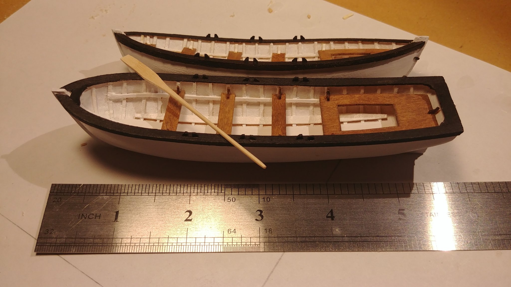
Thanks Charles. I did in fact acquire Leavitt's plans a few months back and have been gingerly proceeding ever since ( see photo of my attempt at the ships' boats ). I understand Chapelle's viewpoint; but my interest in building her is simply I think that this particular design is very lovely, and that August Crabtree built her, and I want to attempt to see how close I can get to his lofty level. That she does not represent an actual ship is immaterial to me. I agree that Feldman and Parker are describing different ships. However, I have Hoeckel's plans too from his monograph Amerikanische Kriegsbrigg. In his bibliography in the back of the monograph, he cites the following: Leavitt, Clyde M, The Brig 'Lexington', Handbook for Model Builder #112, S. 128/137. Fawcett Inc., Greenwich CT. I have been unable to find a copy of this handbook, so if you know a source, please let me know. Between Leavitt, Hoeckel, and Davis, I think the basis of a good model are at hand if my hand/eye skills are up to it. I haven't build a ship model in 40 years, but I did build a 15' sail-and-oar Lincolnville Salmon Wherry a few years back.

-
tkay11 reacted to a post in a topic:
Which wood filler to use
-
As an aside, I would always first apply sanding sealer to the applicable part(s), very lightly sand, THEN paint. That way you won't get odd differences in paint absorption between the wood and any filler.
-
( slowly the dim light bulb comes on ) I just got a copy of Underhill's Plank-On-Frame Models, and his explanation, plus these here, have finally pried open the rusty doors to my understanding what the Leavitt frame drawings mean, and how to proceed. Many thanks-
-
Wonderfully explained and illustrated. I am inordinately impressed.
-
I learn something new almost every time I come here. I have never heard the term' bend ' used at all regarding frames in any of the books I have read, so thank you Jaager. I will check out your build log for La Renommee. Meanwhile, Leavitt DID loft all 37 bends so I don't have to, and I show some of them in my first post. Still unanswered for me is why the Leavitt bend/frame/futtocks are not drawn in fair curves i.e. why the projection at the deck beam level. At this point I have half a mind to simply make bends fair, place them at all 37 stations the way I was taught in boat school, bevel away accordingly, and let the devil take the hindmost. I hate to admit defeat, though.
-
System 3 has a two-part epoxy filler called Sculp Wood that works well. It is lighter in color, however. I suppose one could use Bondo ( automotive filler ) in a pinch?
-
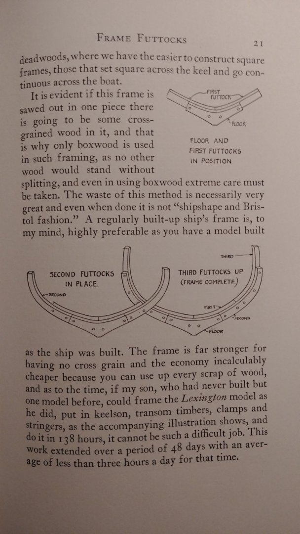
Mark, thanks again, yet still I am as thick as a brick. The projections I was referring to were the ones on the inside or outside of the frames indicating the deck beam level. Charles Davis, in his book The Built Up Ship Model, talks about built-up framing from pages 21-24. The photo herein is from page 21, and clearly shows the projections, but that is because he drew the frame in perspective, no? In other words, am I to assume that the futtocks are all the same molded size for what I will call layer 1 and layer 2 ( both layers, of course, comprising the frame itself ), or am I to cut the futtocks out so that one layer is wider than the other to account for bevel? It seems to me that if the frames were simply futtocks of all the same size for each layer, and placed so that the forward frames were positioned forward of the stations and the aft frames placed aft of the stations, life would be simpler. Aaargh. Davis talks about this, how " the shape of the frame...is the middle of the frame, the seam where the two pieces come together ". He then talks about how one layer is cut on a standing bevel, and the other on an under bevel. Sure, OK, but. Again, aargh. How can the seam line be aligned with the station line of the hull, when the standing bevel layer would need to be larger to accommodate the bevel? I hate the feeling that I am not as smart as I thought I was.
-
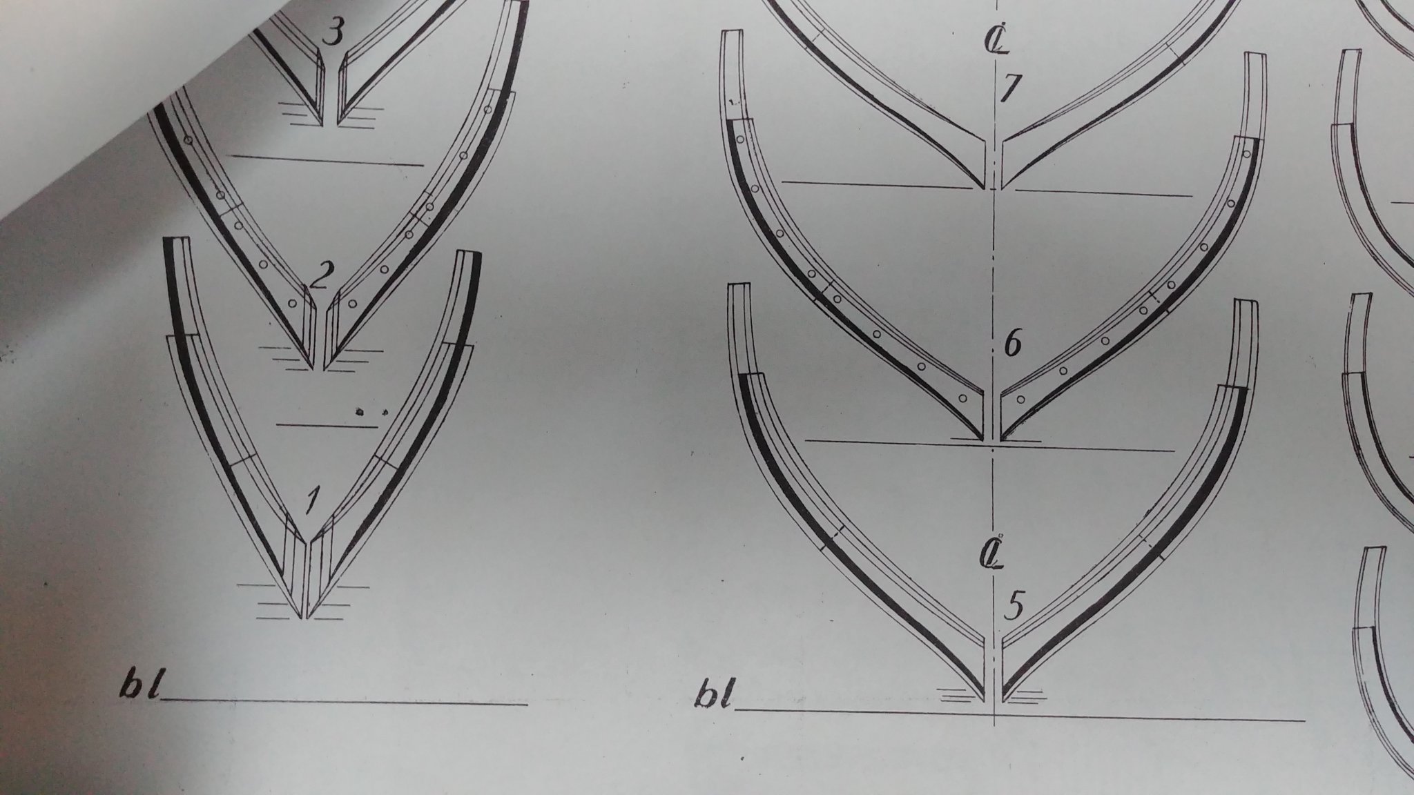
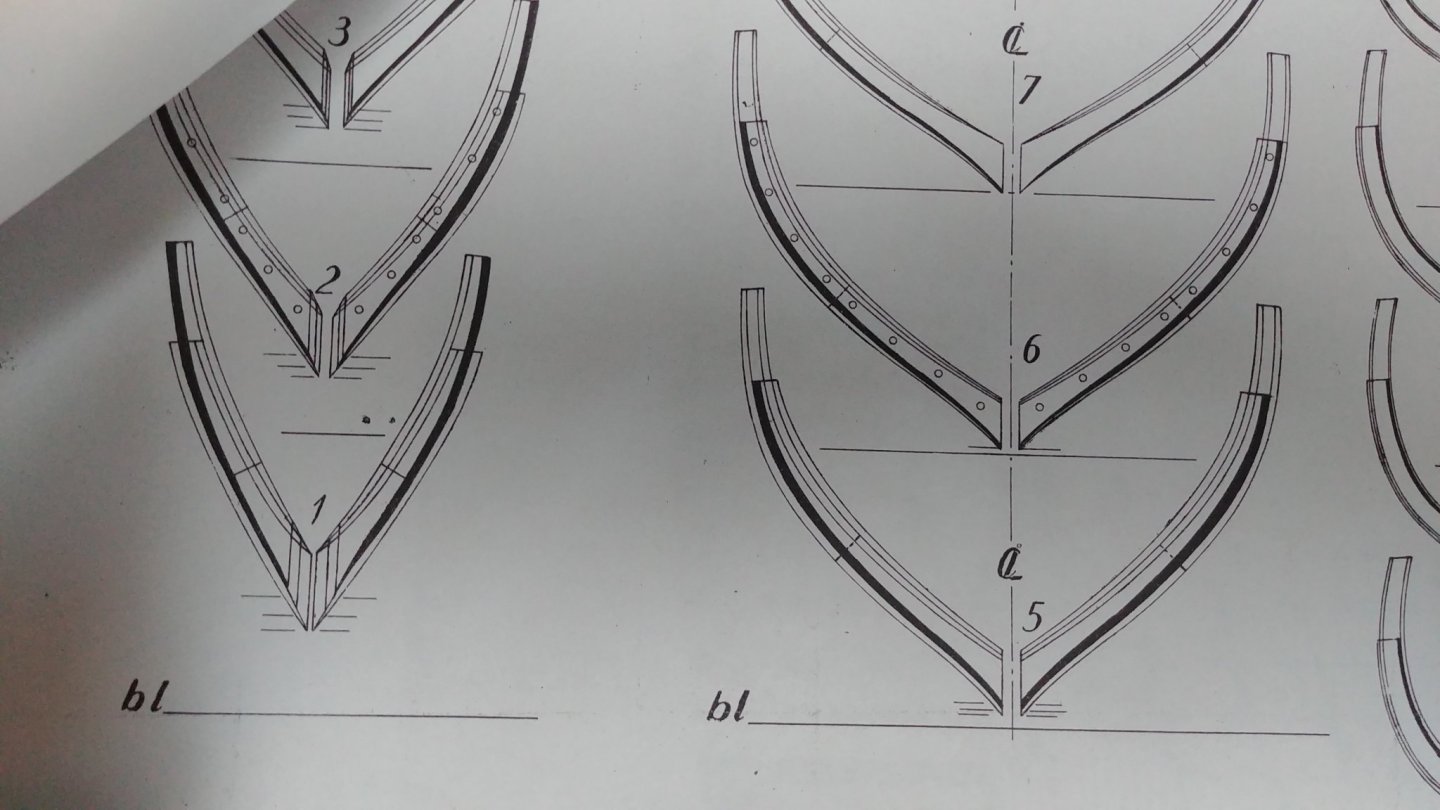
Thank you, Mark. I am still flummoxed by the projections on, for example, cant frames #1 and #2. I wish solid geometry had not been one of my weak points in high school...
-
#9: Succinctly put, thanks. There is a practical and aesthetic difference between deck plugs and treenails in the real world. Accordingly I am thinking that on my 1:48 armed brig c.1810 that I will NOT indicate deck plugs, but will use tree nails in the hull planking.
-
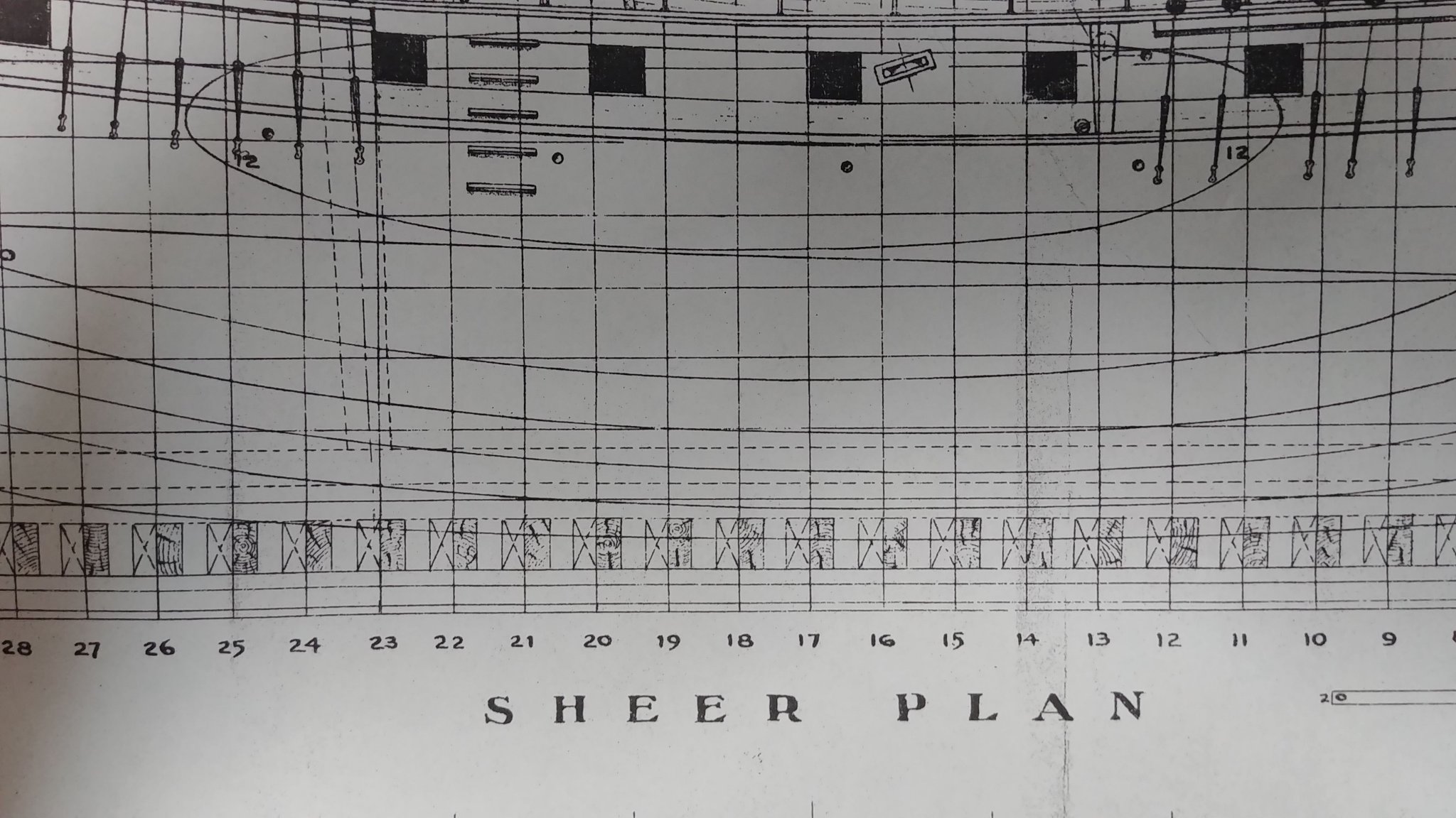
I finally have the Leavitt plans for the Charles Davis Lexington ( so-called ) armed brig, and am puzzled by his frame station layout and his frame plans. See photos. The frames are to be made up with futtocks in the usual manner. What puzzles me is that as you can see, he clearly shows the frames centered on the station lines. I was taught that the frame positions forward of the midship section should be placed forward of the frame station, and aft of the midship station the frames should be placed aft of the frame station, all to allow for the bevels. Then I look at the frame plans, and have not a clue as to why, in certain frames, there are futtocks that project beyond the fair curve of the frame face. Also, there are black shaded areas, some on the outside, some on the inside, but never both. Am I to deduce these are the bevels? Are not the frames beveled inside and outside? What are the multiple of lines showed on each frame? I was expecting something not so rigorous, and being a newbie could use some guidance from the forum. Thanks.

-
As above, Jim sent me his email address, I sent him my questions and he replied within 24 hours, so it's all good. But yes, he really should get that website email function fixed.
-
Jim- Thanks for your response, I will send you an email at that address. Muito obrigado! Gerard>
-
Just curious: twice in the past couple of months I have used the email function of the Byrnes Model Machines website to ask a couple of questions ( there is no direct email address that I can find ) and got zero response. Is he always this uncommunicative?
-
Using pins
Gerarddm replied to Oddball's topic in Building, Framing, Planking and plating a ships hull and deck
Well, yes, and it looks rather jarring, if not actually unsightly in certain cases. If one assumes that trunnels were 1" to 1.5" in diameter , then some models I have seen photos of have trunnels that, when scaled out, would have been several inches in diameter. -
Using pins
Gerarddm replied to Oddball's topic in Building, Framing, Planking and plating a ships hull and deck
He provides no illustrations, and the tenor of his comments were than he pinned for strength.