Ed Ku20
-
Posts
185 -
Joined
-
Last visited


-
 Ed Ku20 reacted to a post in a topic:
Rattlesnake by Ed Ku20 - Model Shipways - 1:64
Ed Ku20 reacted to a post in a topic:
Rattlesnake by Ed Ku20 - Model Shipways - 1:64
-
 davec reacted to a post in a topic:
Rattlesnake by Ed Ku20 - Model Shipways - 1:64
davec reacted to a post in a topic:
Rattlesnake by Ed Ku20 - Model Shipways - 1:64
-
davec reacted to a post in a topic:
Rattlesnake by Ed Ku20 - Model Shipways - 1:64
-
davec reacted to a post in a topic:
Rattlesnake by Ed Ku20 - Model Shipways - 1:64
-
davec reacted to a post in a topic:
Rattlesnake by Ed Ku20 - Model Shipways - 1:64
-
David Lester reacted to a post in a topic:
Rattlesnake by Ed Ku20 - Model Shipways - 1:64
-
JLong reacted to a post in a topic:
Rattlesnake by Ed Ku20 - Model Shipways - 1:64
-
Dave_E reacted to a post in a topic:
Rattlesnake by Ed Ku20 - Model Shipways - 1:64
-
whitejamest reacted to a post in a topic:
Rattlesnake by Ed Ku20 - Model Shipways - 1:64
-
Gregory reacted to a post in a topic:
Rattlesnake by Ed Ku20 - Model Shipways - 1:64
-
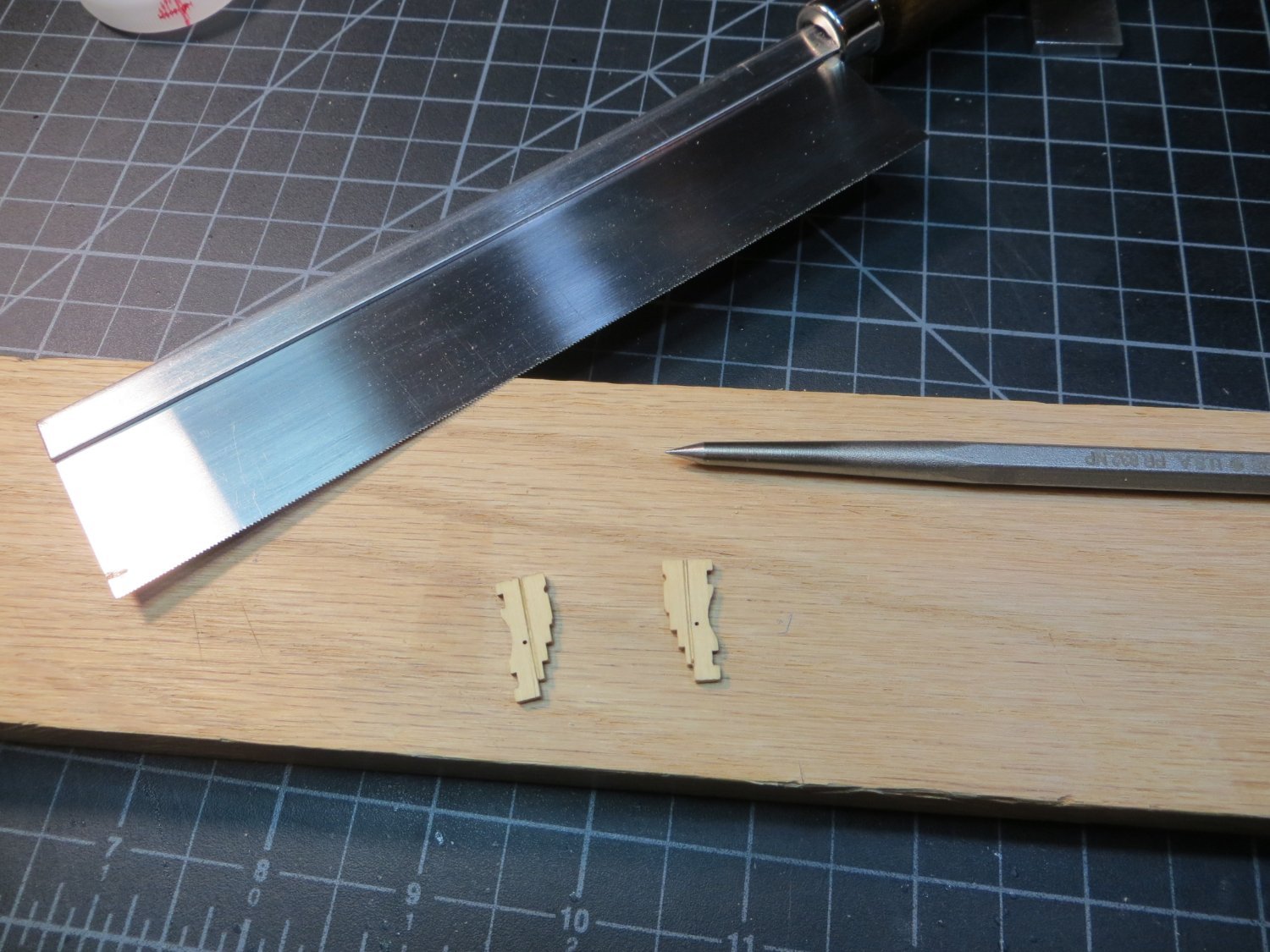
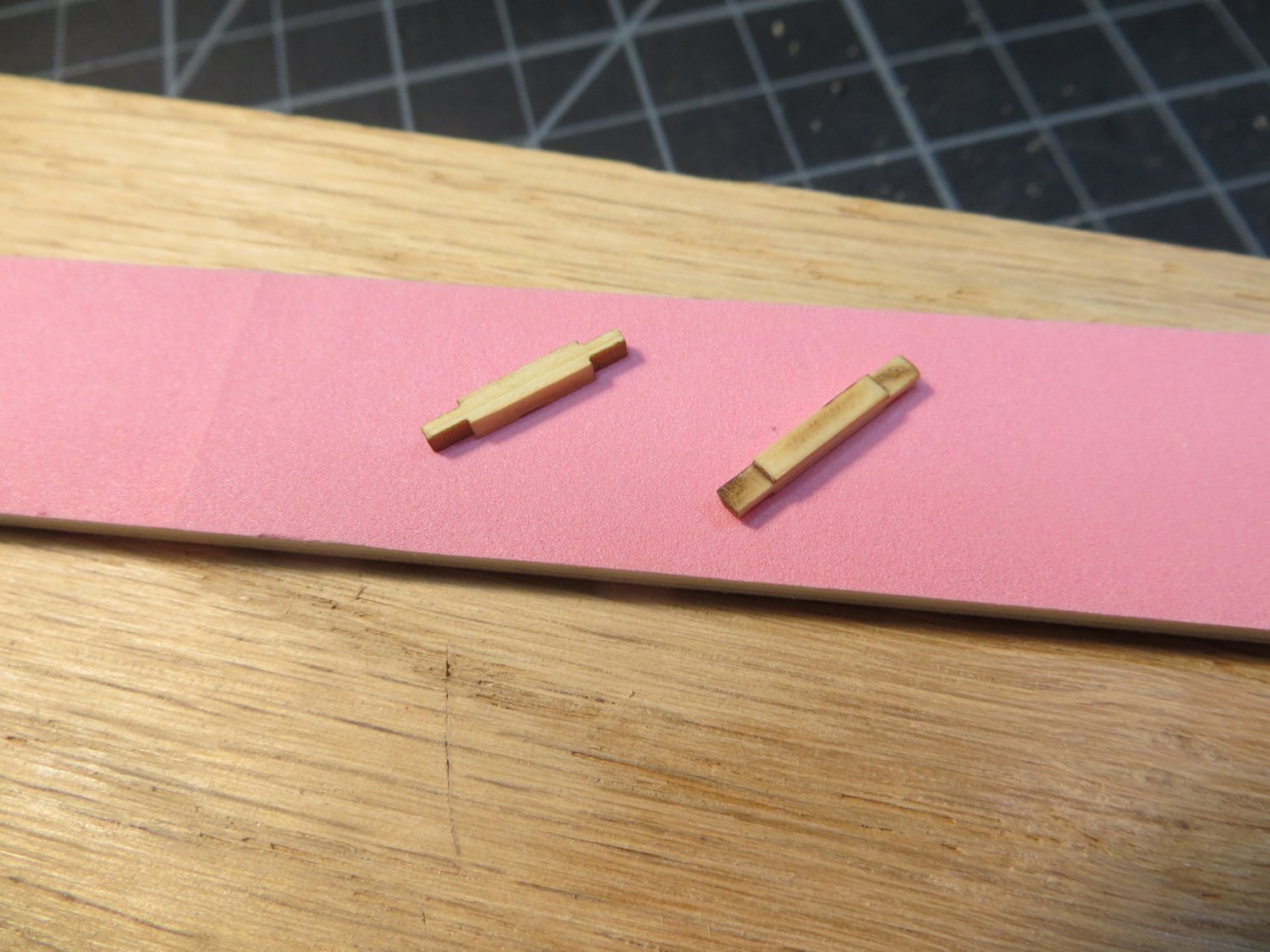
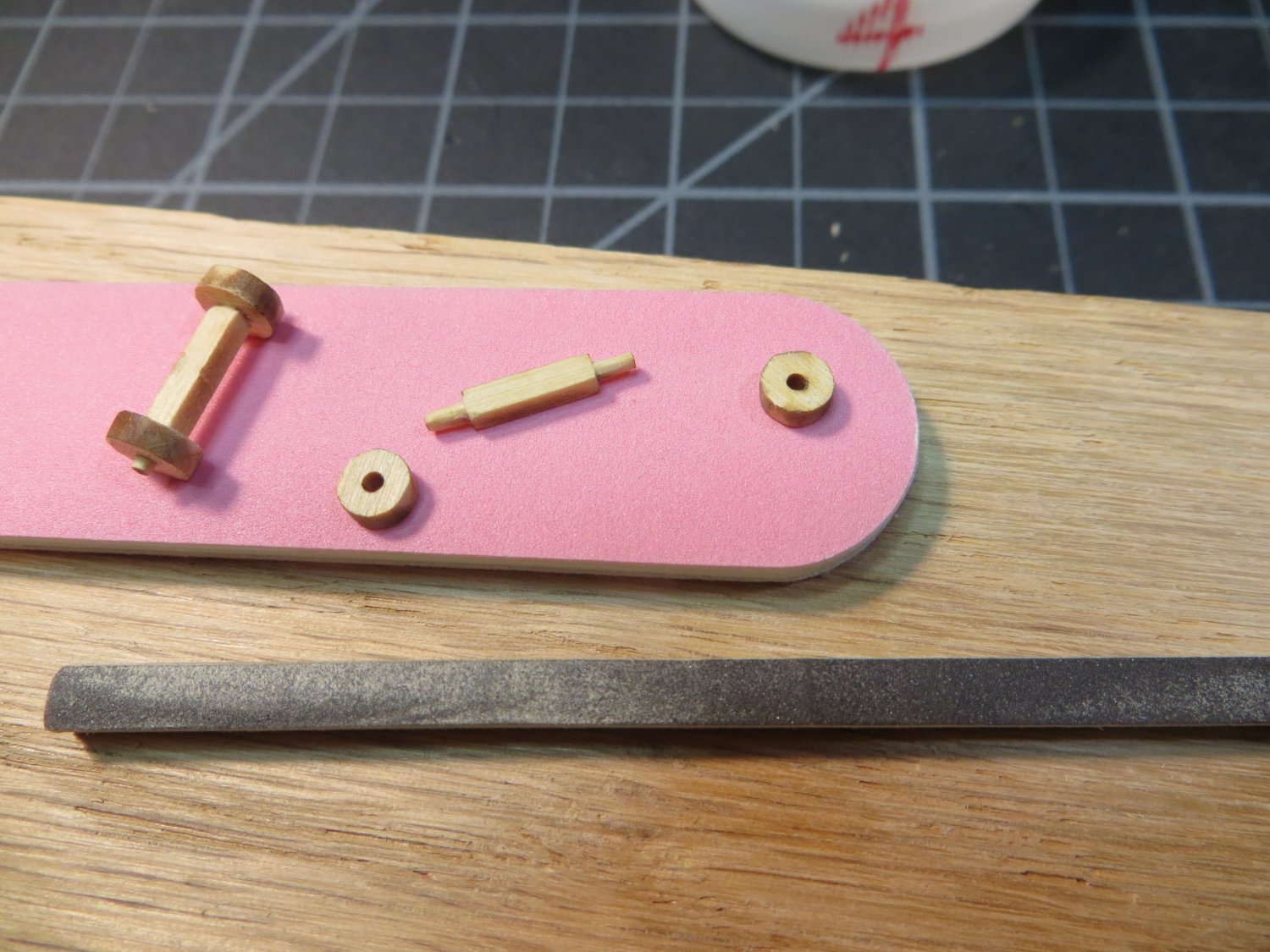
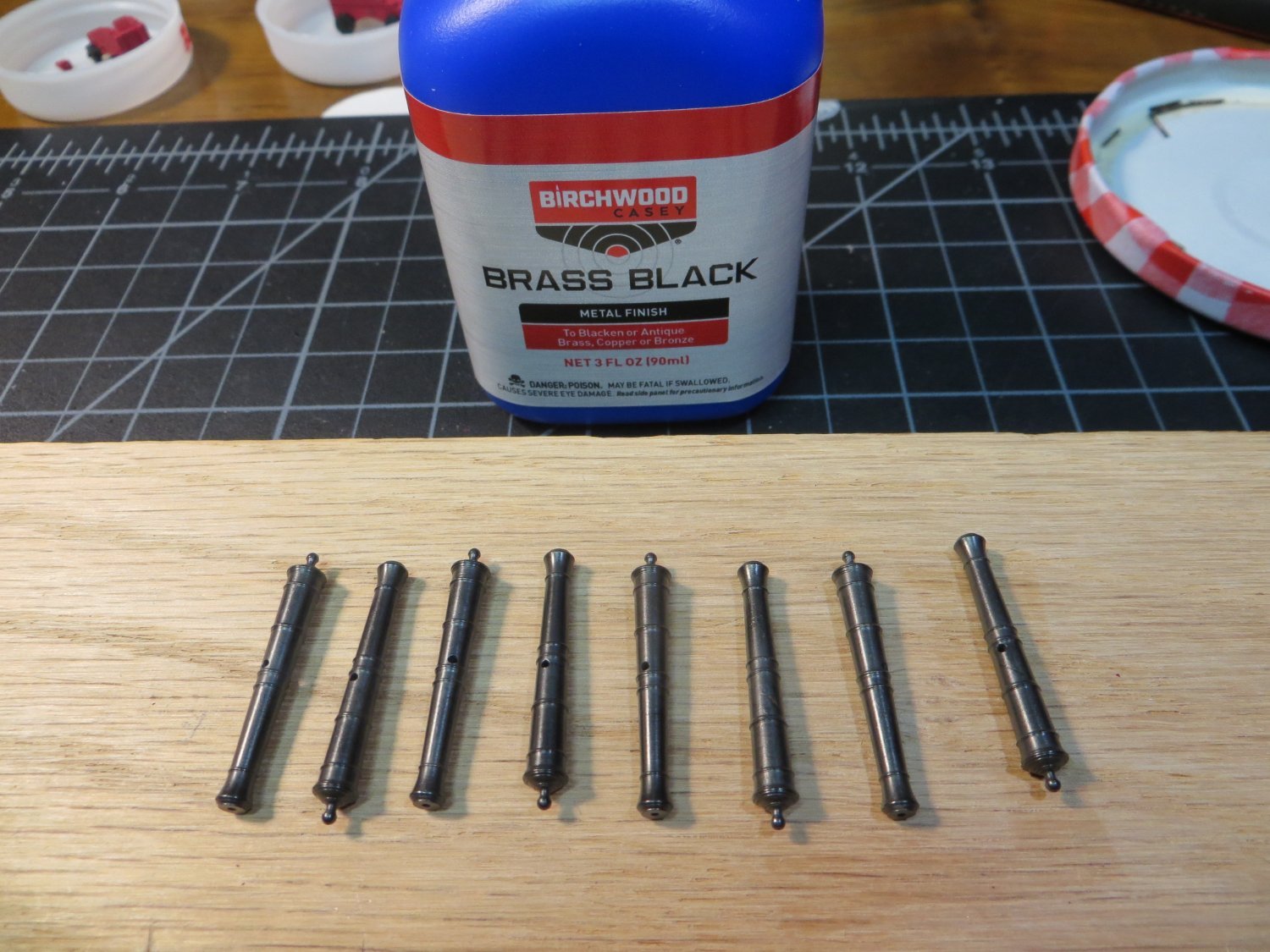
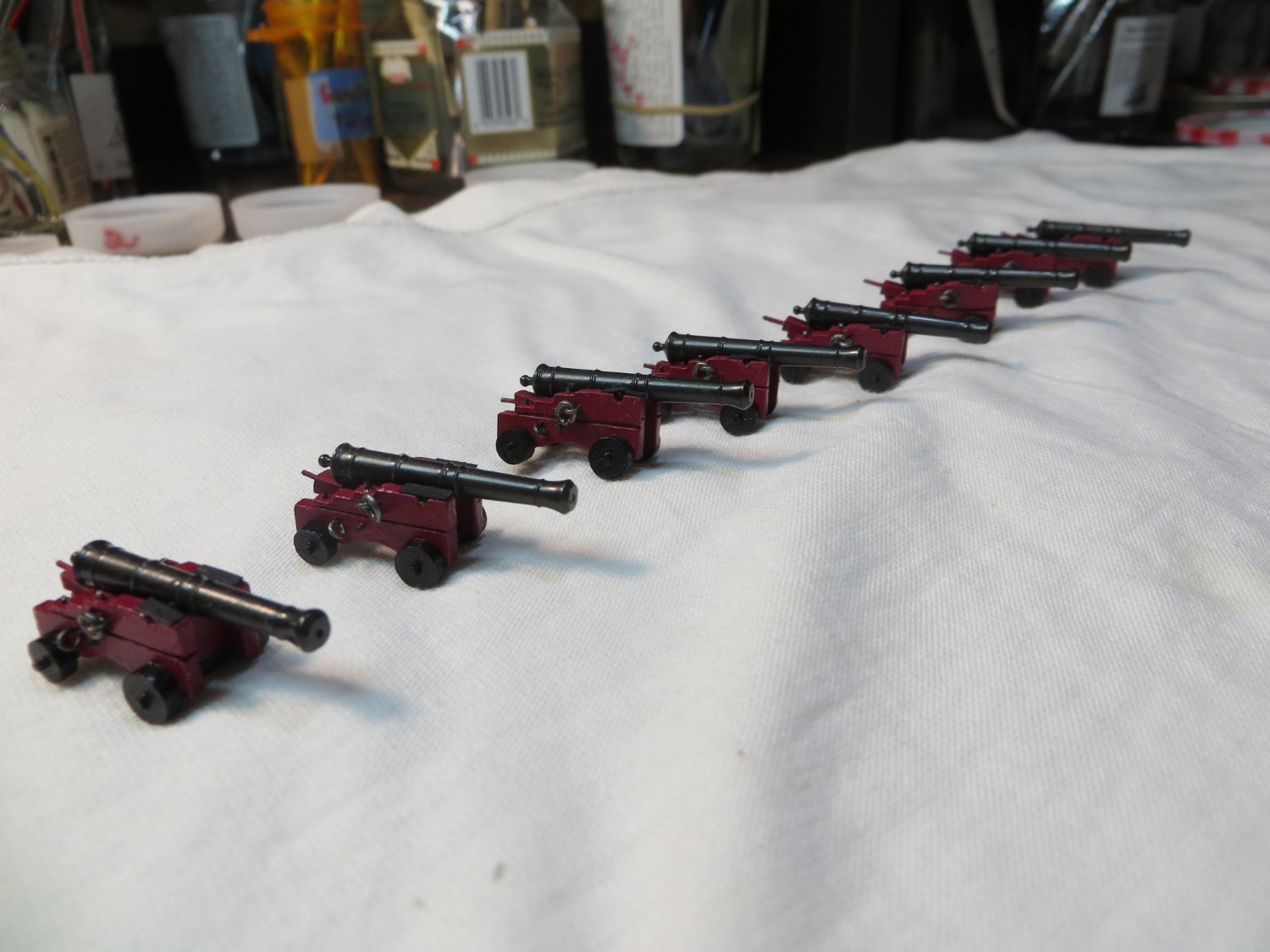
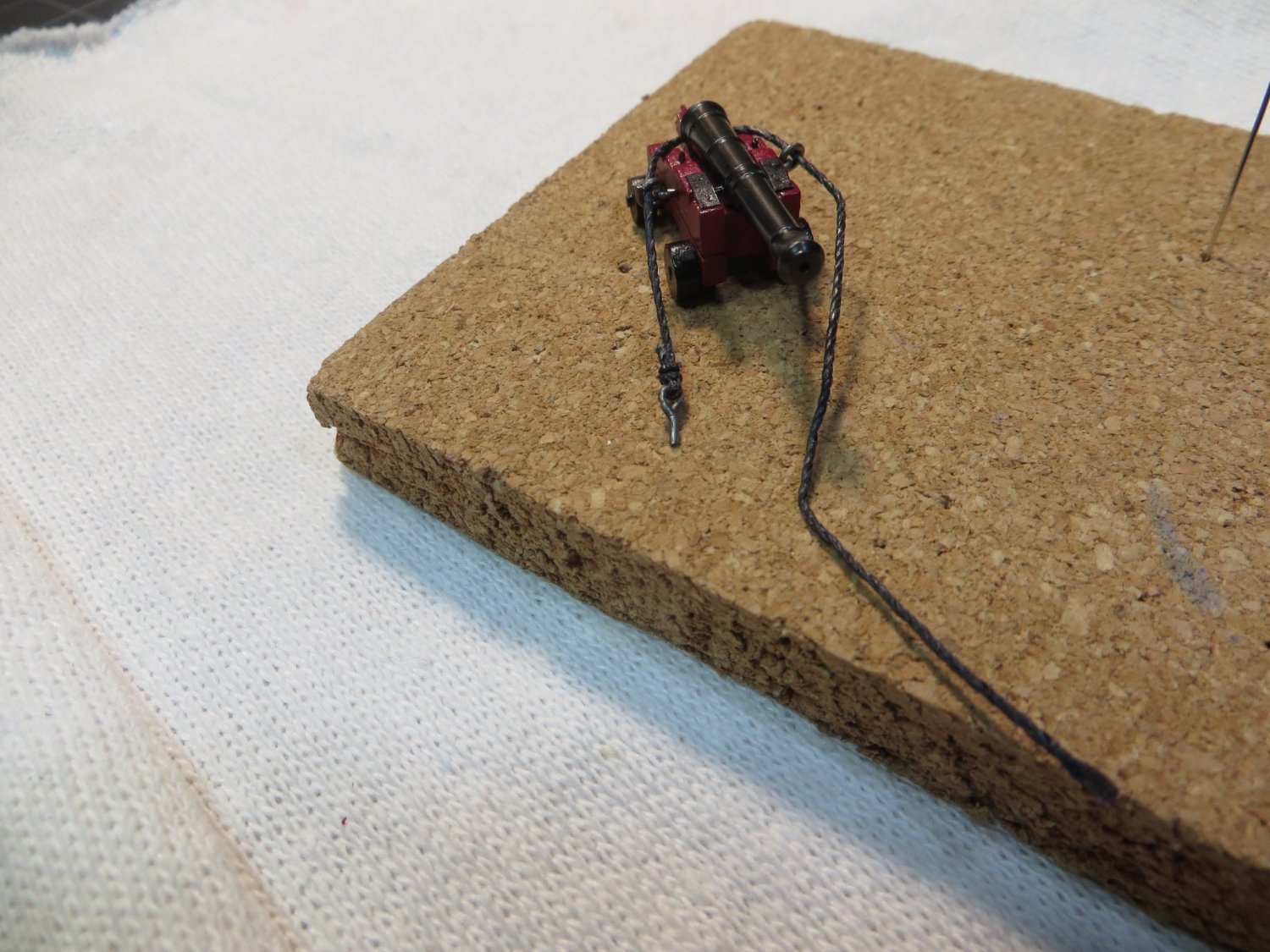
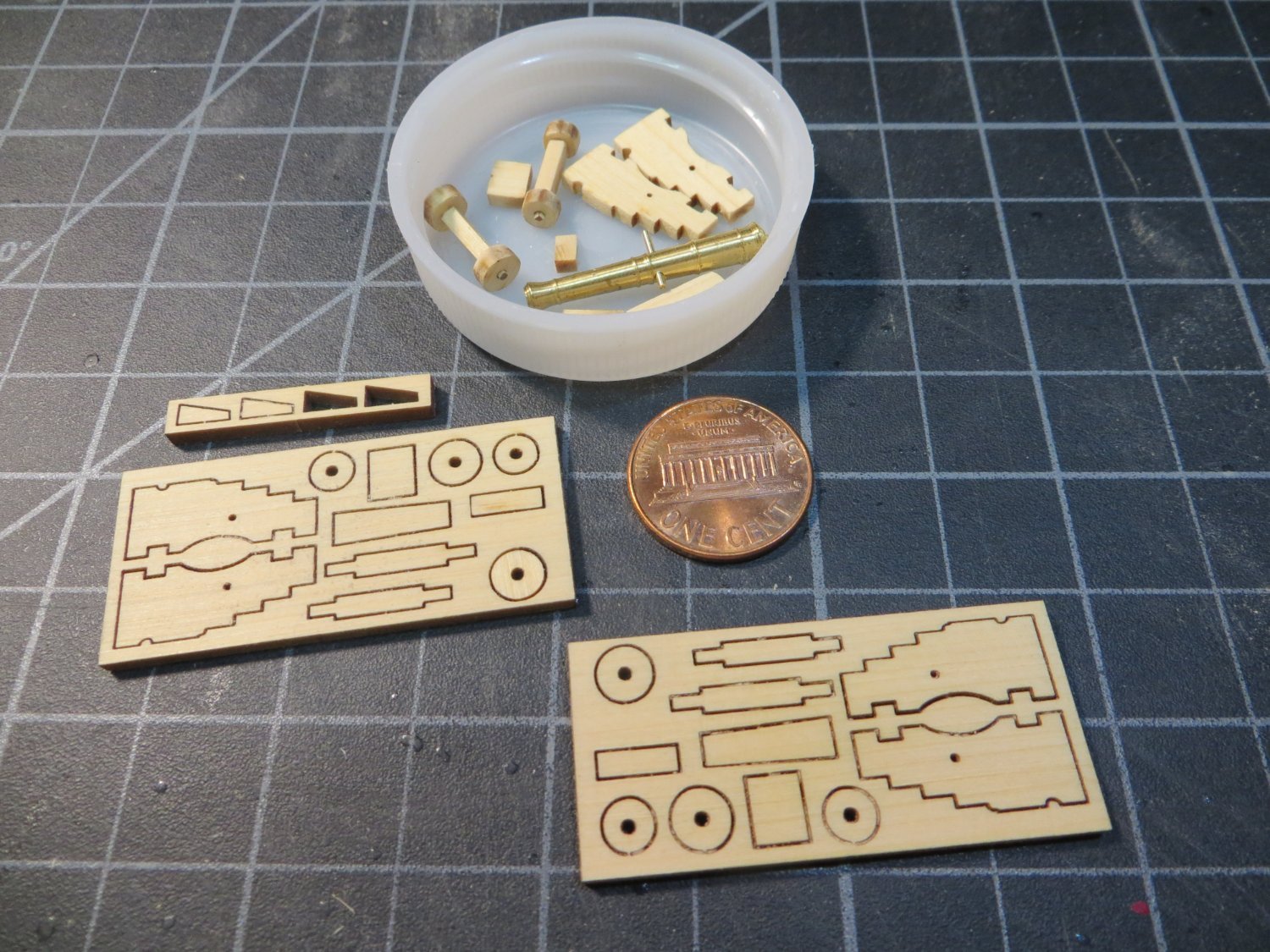
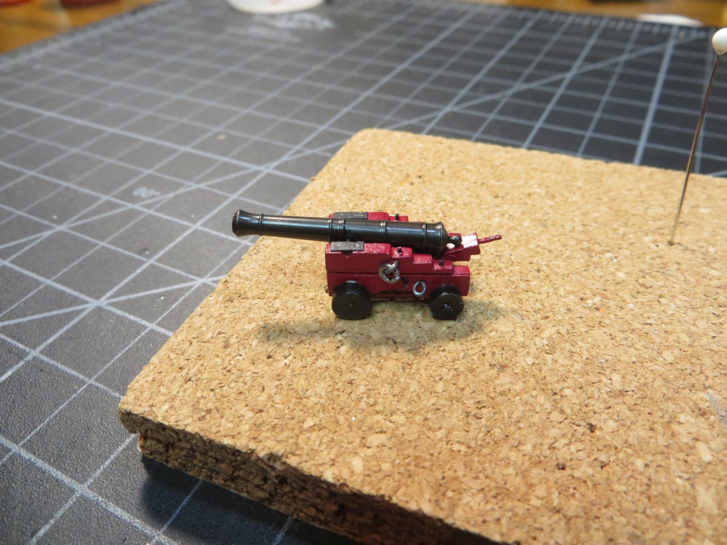
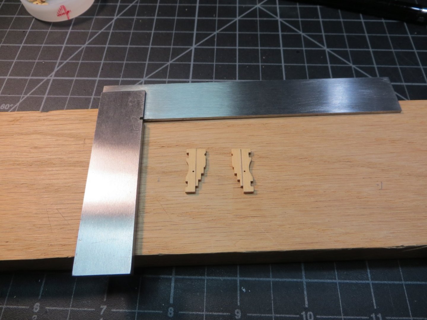
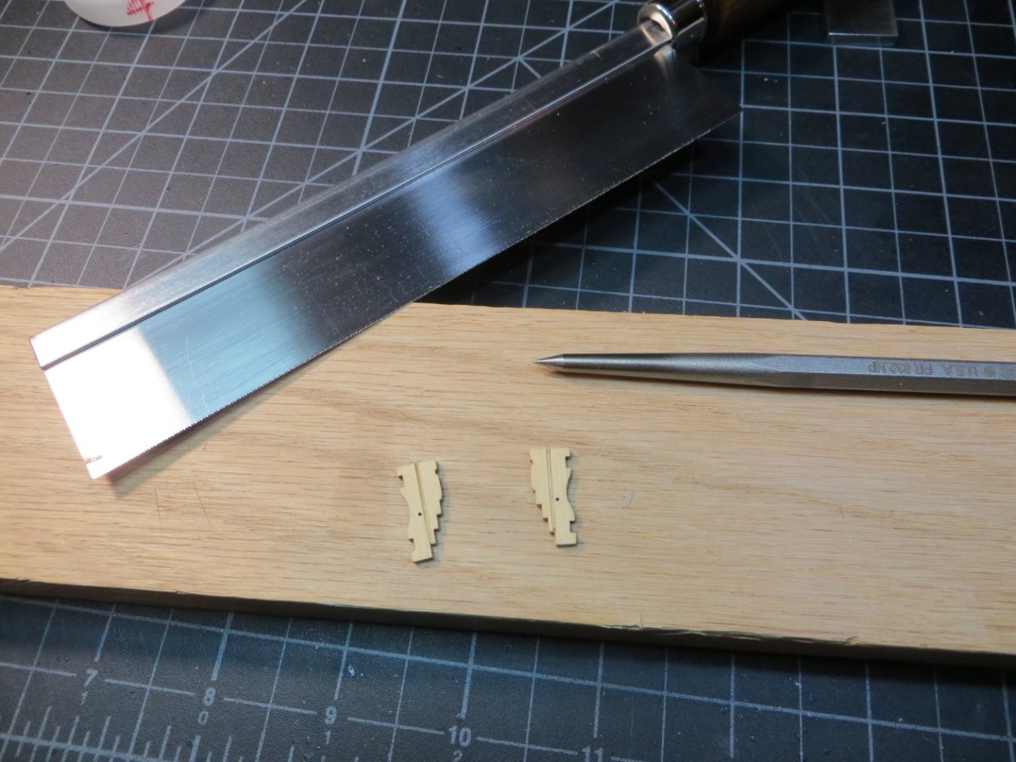
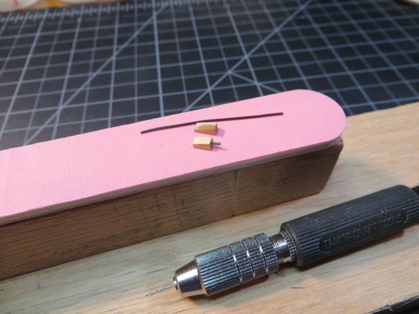
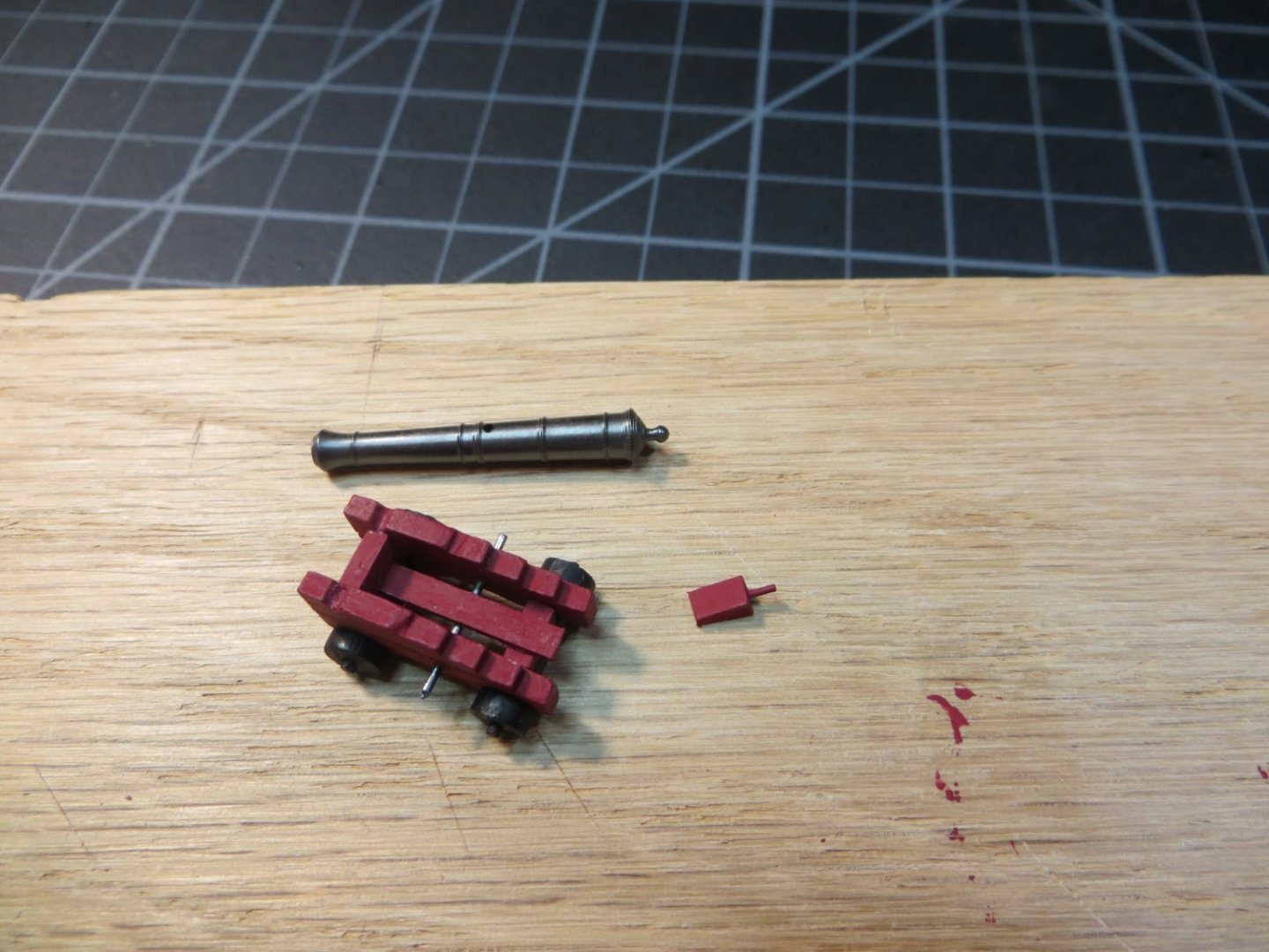
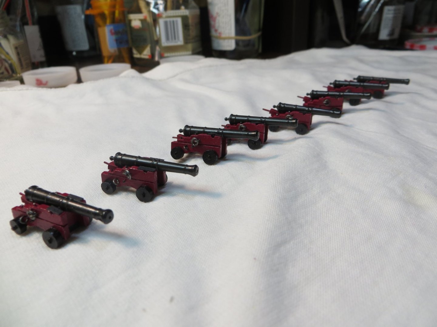
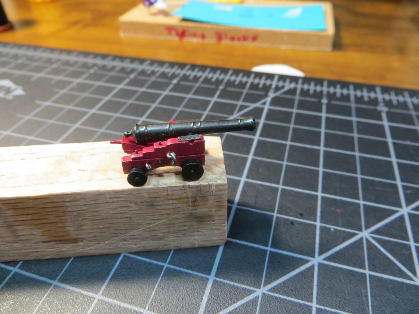
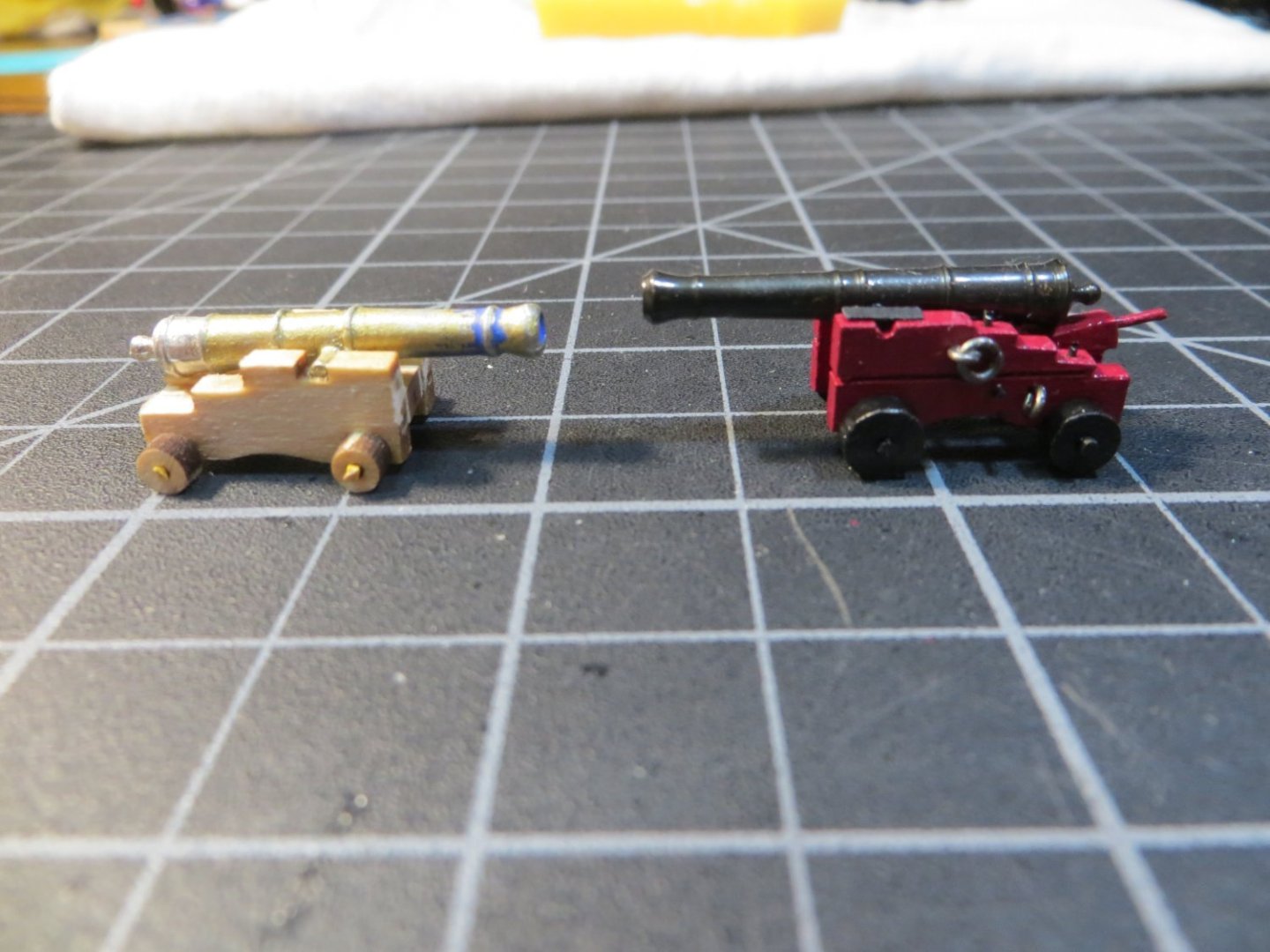
 Completing the final 8 Cannons for the Gundeck While there is still open space to work on the gundeck I decided it was a good time to build and install the last 8 cannons. I made 4 cannons that are under the Focsl Deck several steps ago. at that time, I did not go into any details on how the cannons are made. This time I thought I would write-up something for anyone who is thinking about using the Syren Ship Model Co. cannons and carriages. I don’t know if I’m just slow or really anal, but it took me 50+ hours and the month of March to make these 8 cannons. There are a lot of details involved with these beautiful cannons. This post will only cover the assembly of the carriages and cannon barrel. I am just starting on the rigging now and will provide another post when I’m done. I decided to make them in two batches of 4. For the most part, I performed each step on all 4 of them at the same time. When I get a technique and a rhythm going, I like to keep it rolling! Here are all the carriage parts after removing them from the laser cut sheets. Laser char has also been removed. First thing I did was to deepen the grooves for the cannon barrel and axles with files. This was necessary to make them fit the height of my gun ports. Chuck’s instructions suggest scribing a cut into the sides of the carriage frames to make it look like an upper & lower half are bolted together from the top. Below I drew a pencil line with the square to mark the line I used a razor saw to make the cut along the line. On my first four that are under the Focsl I thought the cut wasn’t wide enough to see. So, this time I used this fine point punch to make the line a little thicker. The axles come in two sizes. The shorter one goes in front with the larger wheels. The carriage is wider in the rear, using a longer axle. The part where the wheel fits on needs to be sanded into a rounded shape. Must be careful not to sand it too much. I made mine with a tight fit. Next is the “Quoin”. The wedge-shaped block used to raise and lower the cannon. I sanded mine smaller to accommodate the height issue. The handle is supposed to be turned using a Dremel to give a piece of wood the shape of a belaying pin. I didn’t like the way these turned out for me. So, I just used a short length of annealed steel wire and painted it. Another piece of this wire is used to hold the carriage sides together. The bed sits on this wire too. I substituted a 1/32” x 3/32” piece of stripwood to make the bed shorter. I painted all the parts before assembling them. Red for the carriage and black for the trucks & axles. Here is the assembled carriage. I placed a drop of thin CA glue into the hole to hold the wire in place before snipping off the ends. A bit of the end is left sticking out to simulate a bolt. I treated the brass cannons with this Brass Black metal finisher. It took two applications to get them looking evenly treated. After wiping off the residue from the chemical (twice), I used a cloth buffing attachment in the Dremel to polish them to this finish below. I think this looks more realistic than using black enamel paint. Several finishing touches make the gun look pretty awesome. A couple of more wire “bolts” are inserted on top of each side frame. Tiny strips of black card stock are glued on to look like plates holding the barrel in place. And finally, 4 eye bolts and 2 rings are attached for use with the rigging. 1 month later the arsenal is ready for rigging and installation on the ship! Just for the sake of comparison, on the left is the kit supplied cannon. Obviously, it’s not finished, but you get the idea. Also, I’ve read that the brass black does not work on Britannia metal. If you do decide to use the Syren cannons, build your gunports a little taller so they will fit more easily. These are supposed to be the right scale, but you can see how the kit ones are shorter and squattier. Hope this information is helpful for someone out there! Next up is rigging the cannons. Thanks, Ed
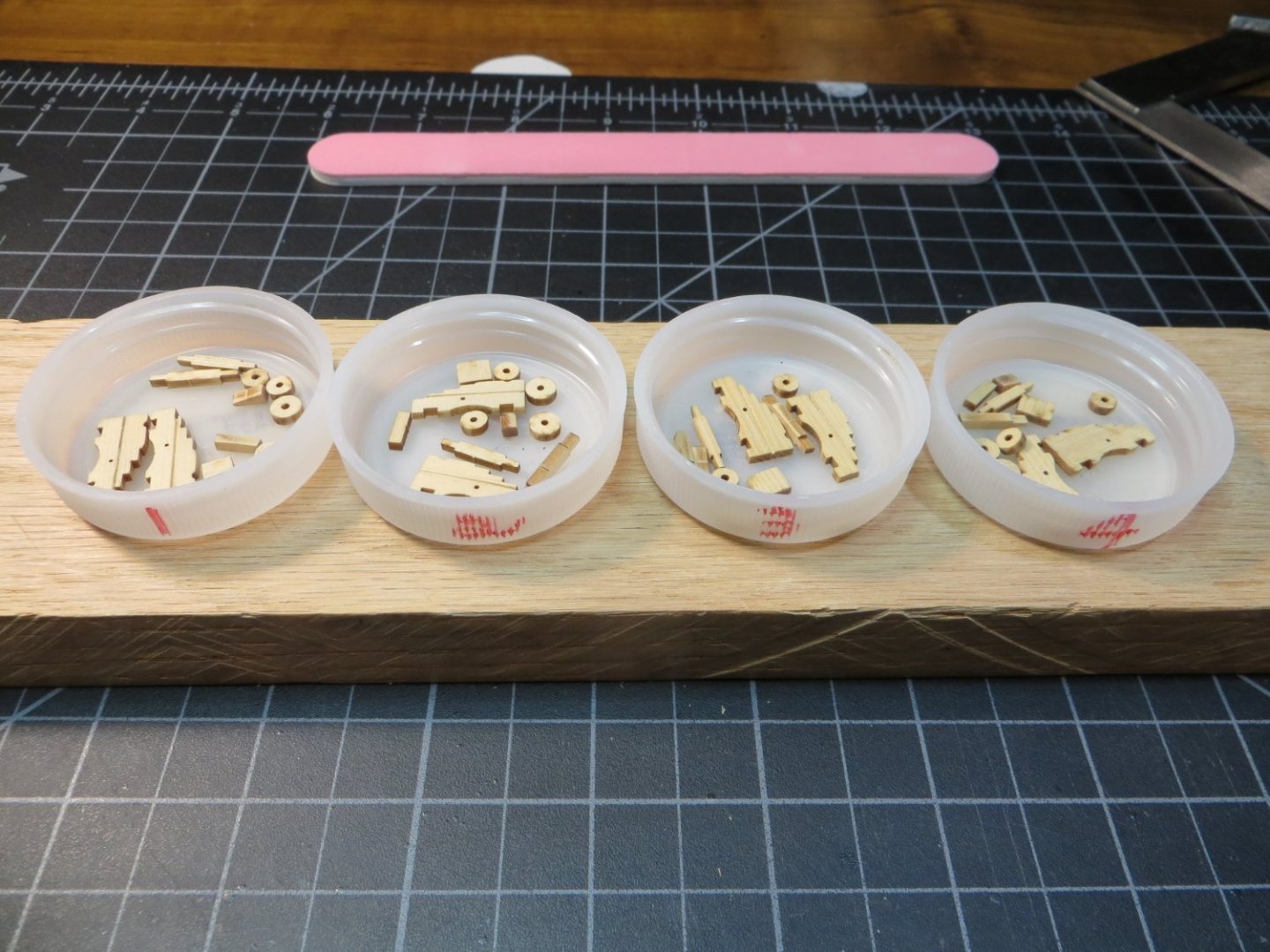


-
GGibson reacted to a post in a topic:
Bluenose 1921 by GGibson - Model Shipways - 1:64
-
Hi Gregg & All, I'm happy to see that you have found my Bluenose build log to be helpful to you with your own build. I really enjoyed building Bluenose and creating the log. I continue to be active on model ship world with my current build of the Rattlesnake. Feel free to contact me if you have any questions about my Bluenose log. Thanks, Ed
-
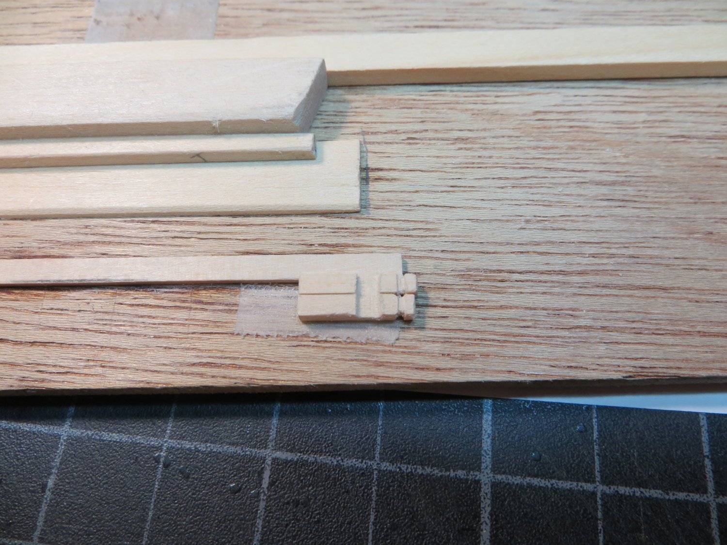
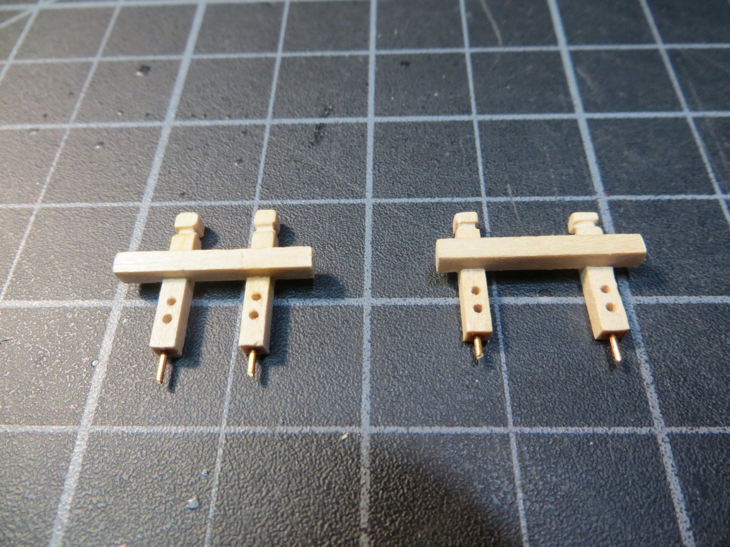
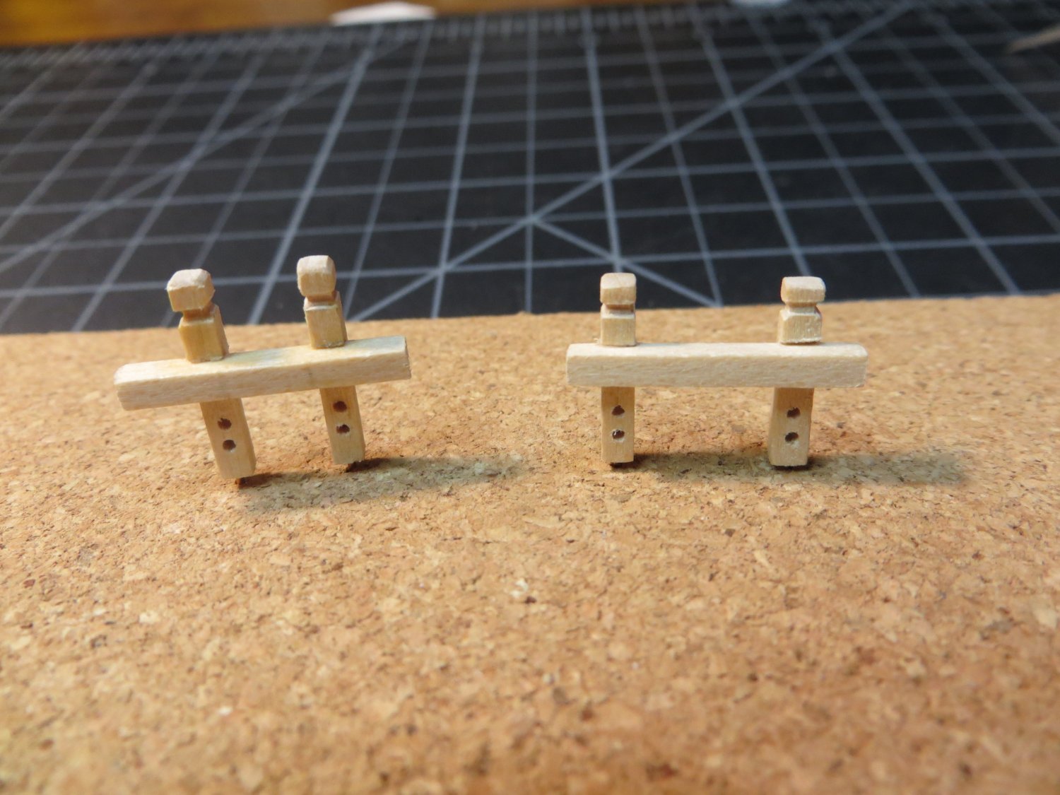
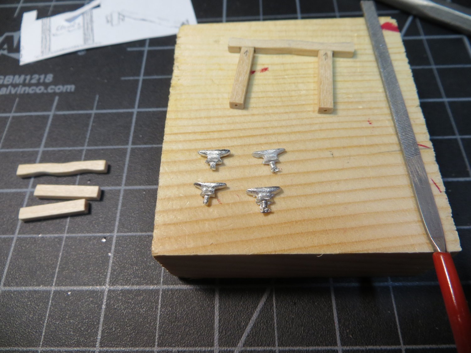
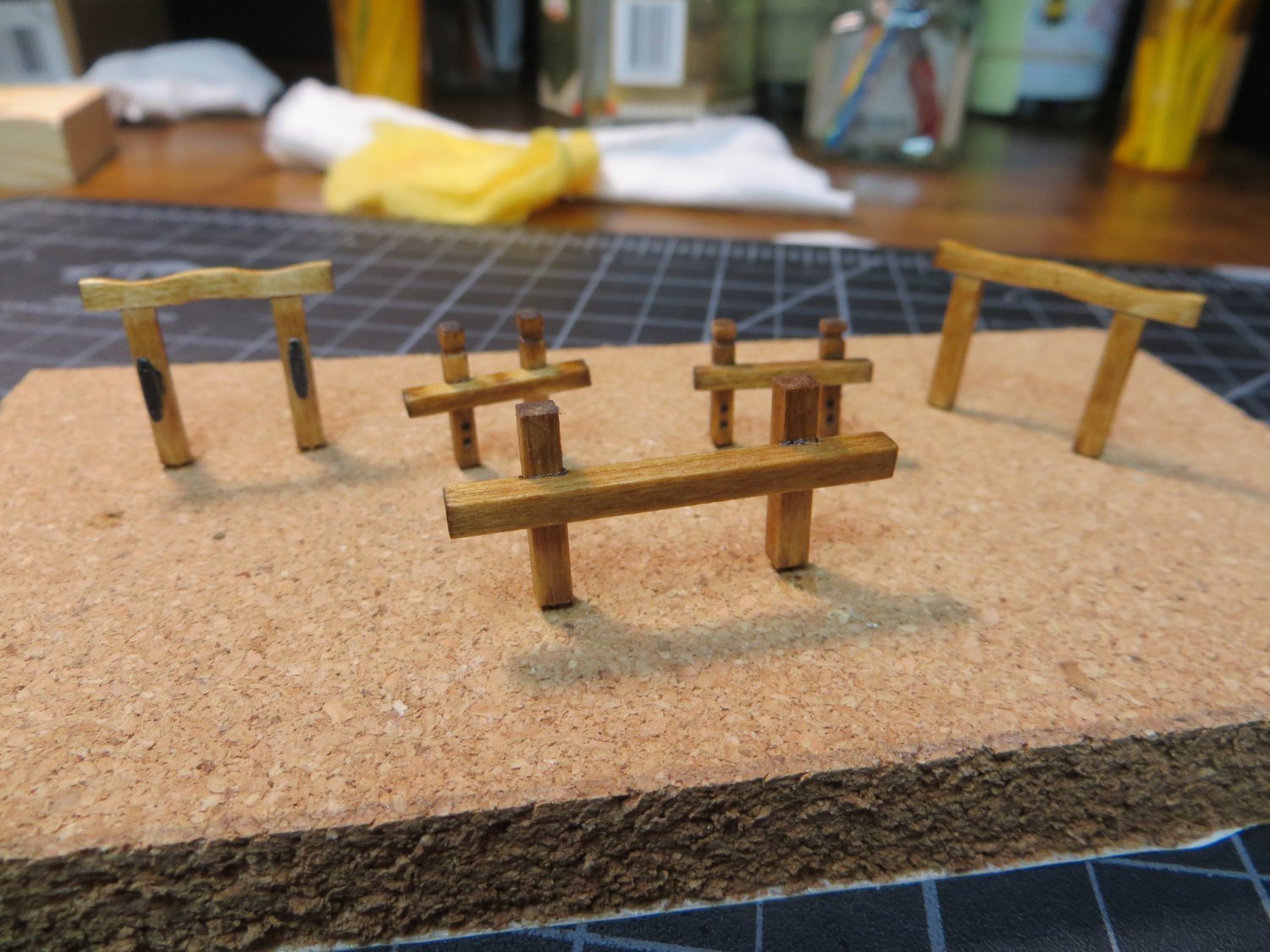
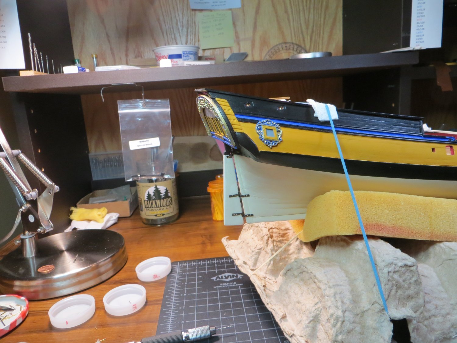
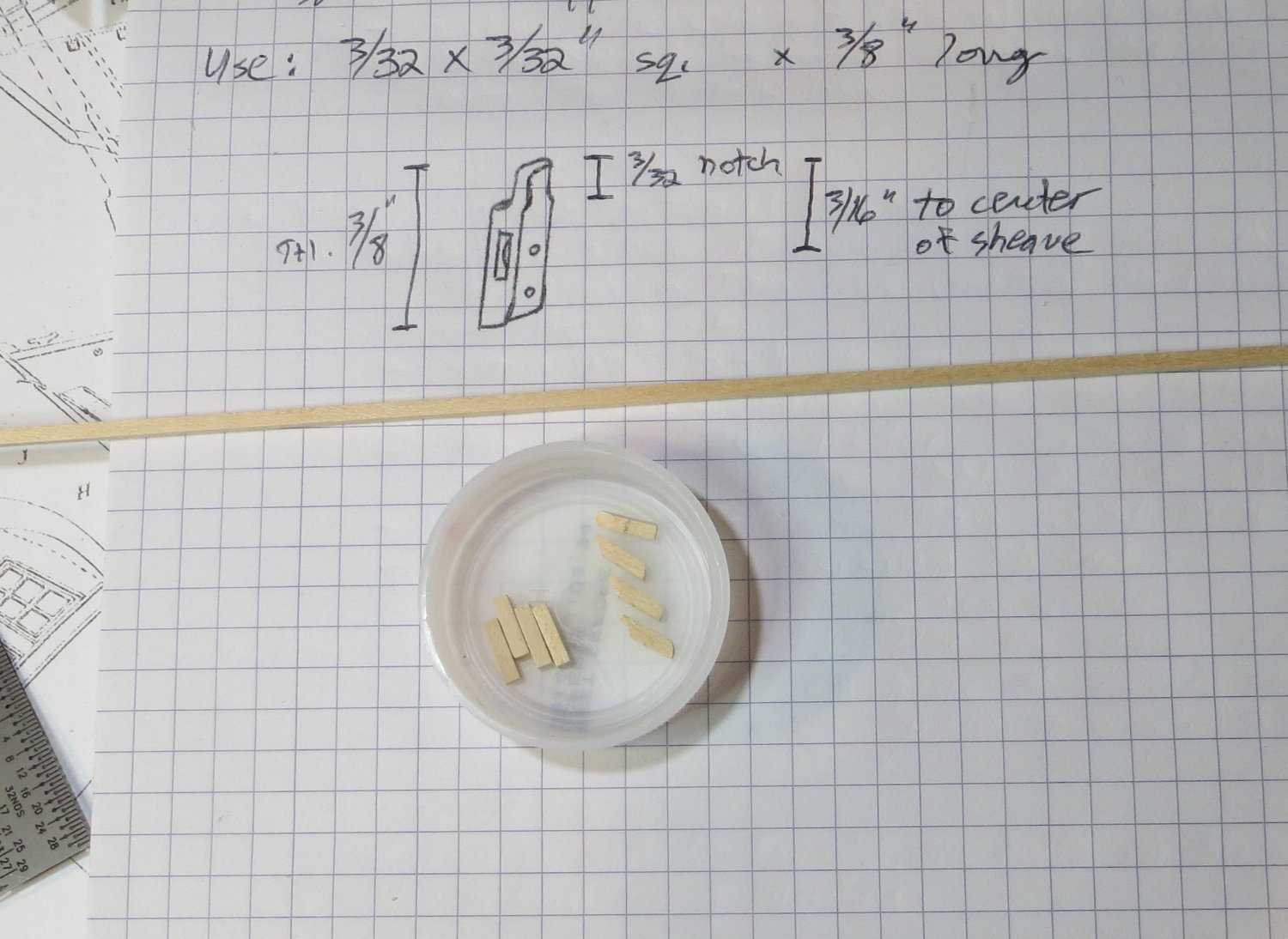
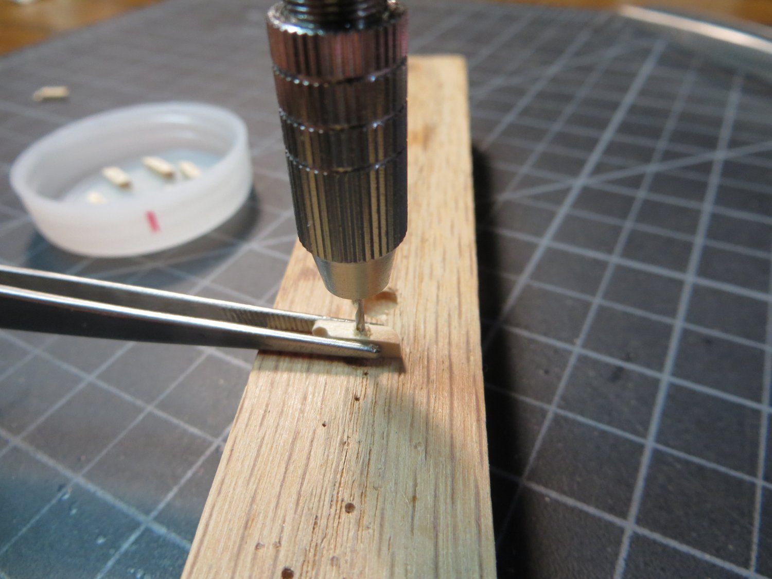
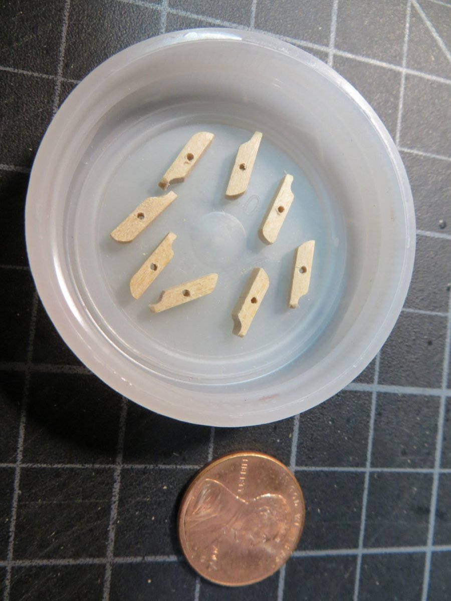
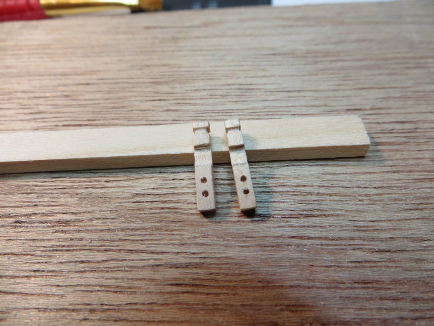
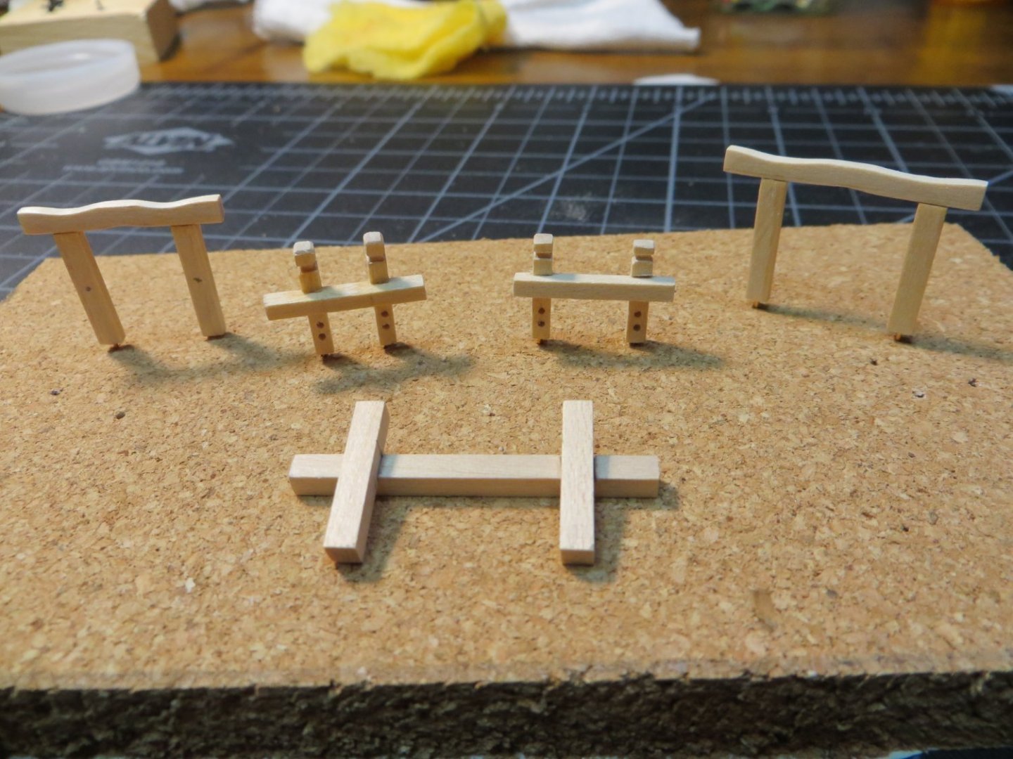
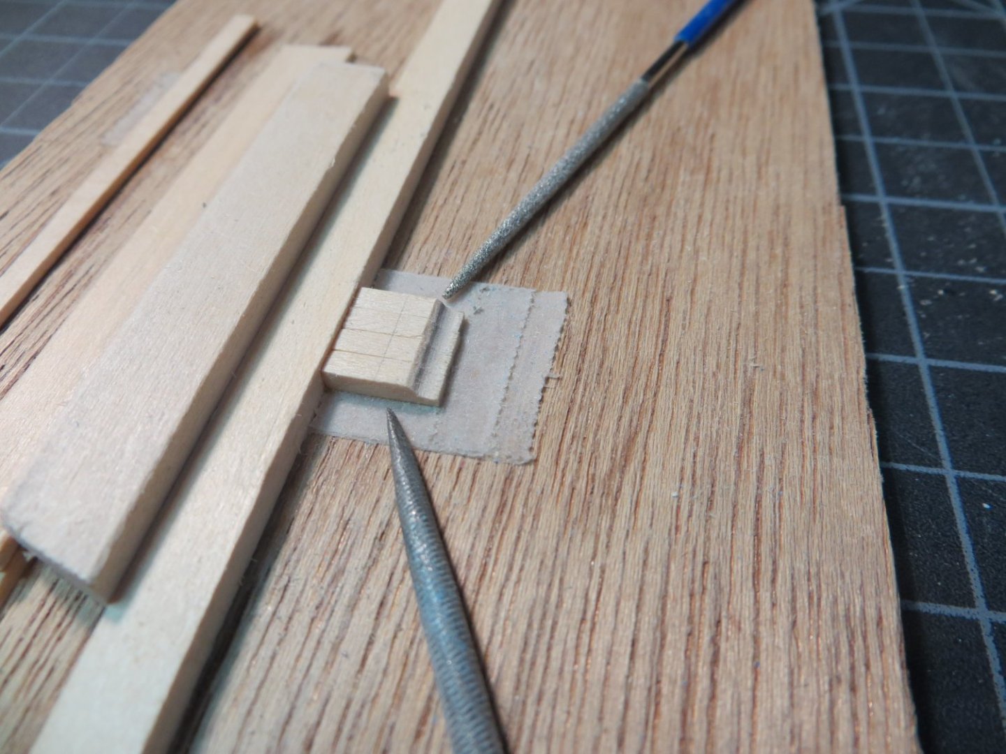
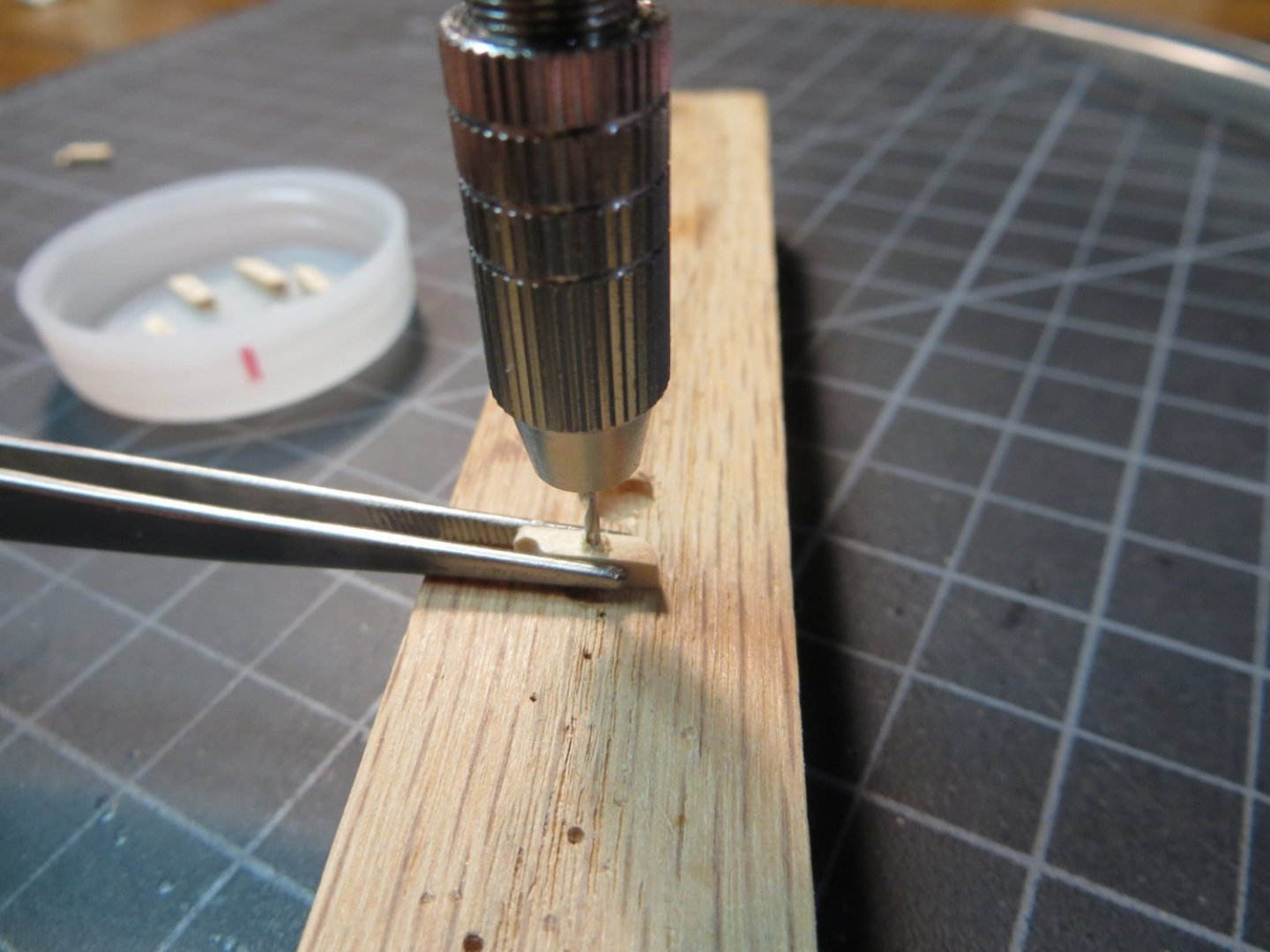
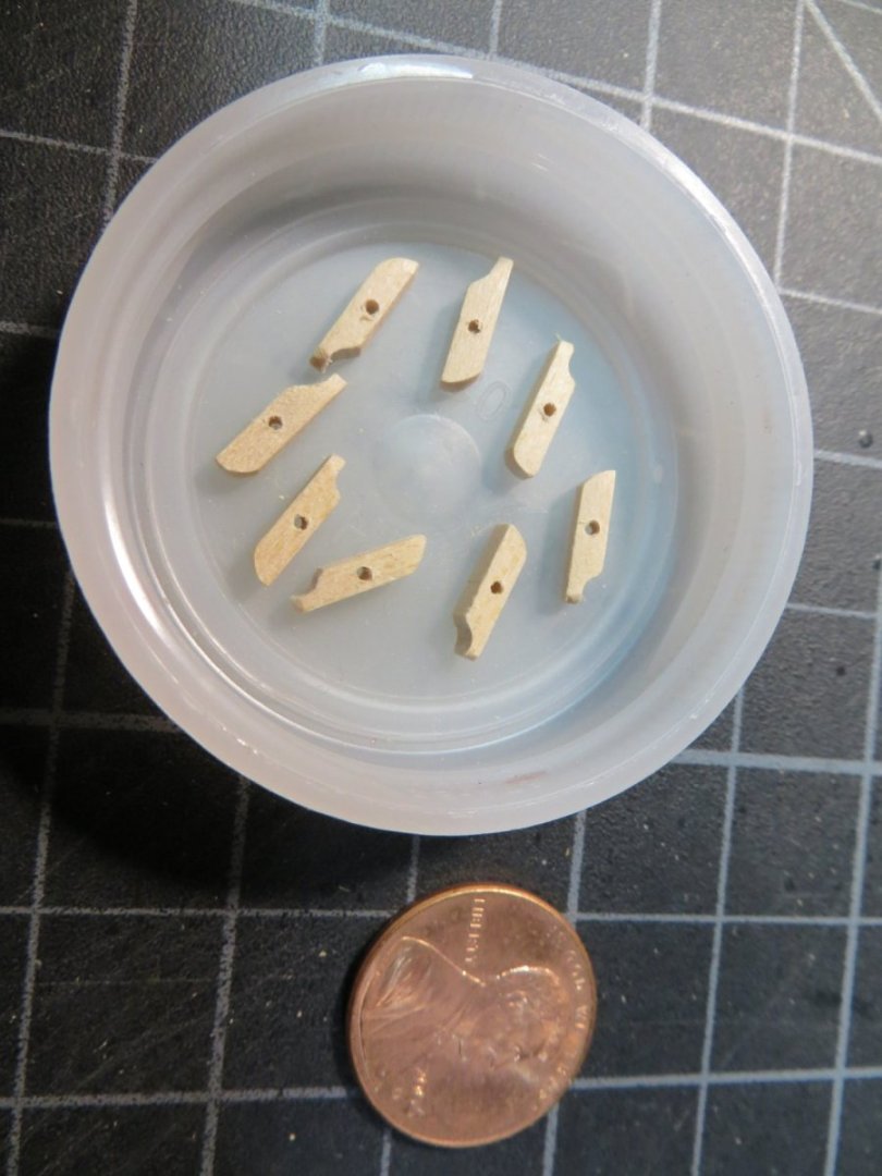
The 5 Bitts I just completed the Bitts. There are five Bitts on the Rattlesnake. These pieces are provided in the kit as Britannia metal castings. 1. Topsail Sheet Bitts – stand in front of the fore mast on the focsl deck 2. Fore Gallows Bitts – stand behind the galley stack on the gundeck. It holds the spare yard arms that the long boat sits on 3. Riding Bitts – stand under the long boat. This one has a short, thick pair of posts. It is used to secure the anchor line when the ship is at anchor 4. After Gallows Bitts – stand before the main mast. It holds the aft end of the long boat 5. Fore Brace Bitts – stand right behind the bulkhead beam of the quarter deck I don’t like the metal castings for these. I don’t think it will be difficult to kit-bash these out of stripwood. The hardest part is finding the right size pieces of wood to use. The measurements for the cast metal do not match what’s in the plans anyway. I’m not going to get too worried about an exact match. I made all my measurements from the blueprint plans. For anyone who is interested, here is the process I used. Topsail Sheet & Fore Brace Bitts: Both of these are very similar in design and size. The cross beams are both approximately ¾” wide. The Topsail bitts posts are shorter @ 7/16” and they are closer together. The Fore Brace bitts is taller @ ½” and the posts are spread wider apart. They both require holes in the posts to simulate sheaves. I used 3/32” square stripwood to make all these parts. · Measure and cut the 3 pieces of wood for each · I cut the posts 3/32” longer to make a decorative carved top. I got this idea from David Lester’s Rattlesnake build. · I carved out the top first using mini-files & then cut the post to length · Filed out a notch where the cross piece needs to fit into the posts. I have a file with the right width! · Drill holes for the sheaves with a pin vise · Drill a hole in the bottom of each post and CA glue an artistic wire pin to secure them to the deck · Glue the parts together · I stained all 5 of the completed bitts at the end using Minwax Golden Oak. 3 coats to deepen the color Fore & After Gallows Bitts: Both of these are the same in design. The Fore Gallows is narrower than the After. Also, the fore gallows have cleats on the fore & aft sides of both posts. The After Gallows has no cleats. Use 3/32 x 1/8” stripwood for both cross beams. I selected the wider 1/8” strip to allow for the curved shapes that need to be sanded into the cross beams. Measure and cut the 3 pieces of wood for each · The top cross beams require some curves to be sanded in on both · Drill a hole in the top and bottom of all the posts to insert pins that will act as dowels to anchor the cross bars and secure the bitts to the deck · Prepare kit supplied Britannia cleats. (Left pair filed and ready; Right pair just out of their bag) · Glue the parts together Riding Bitts – This is a shorter but more “massive” bitt for holding the anchors! Use 1/8 x 1/8” square stripwood. The cross beam is inset into notches on the posts. The steps are similar to the topsail bitts, except there is nothing additional required. The 5 Bitts are ready for staining Bitts after staining. Note the cleats on the Fore Gallows Bitts in the upper left corner. I think mine are better looking than the metal ones from the kit! But I’m biased!! I plan to build, rig & install the last 8 cannons before I attach the assembled Bitts to the decks. I need room to work. I did glue down the assembled hatches, since these are low and will not be in the way. In fact, I need to know where they are located when I lay down the coils of rigging ropes for the cannons. I also attached the pad for the galley stack and the galley stack on top of it. The plans show this skewed toward the port side. A hole was drilled first through the pad and then through the deck after the pad was glued down on the deck. I used thick CA glue to attach the stack. Here is a pic of the ship at the current time. My next step is to work on the remaining cannons for the gundeck. Thanks for looking in on my progress! Your comments & questions are always welcome. Thanks, Ed


-
Thanks Dave! I really appreciate your kind words. Ed
-
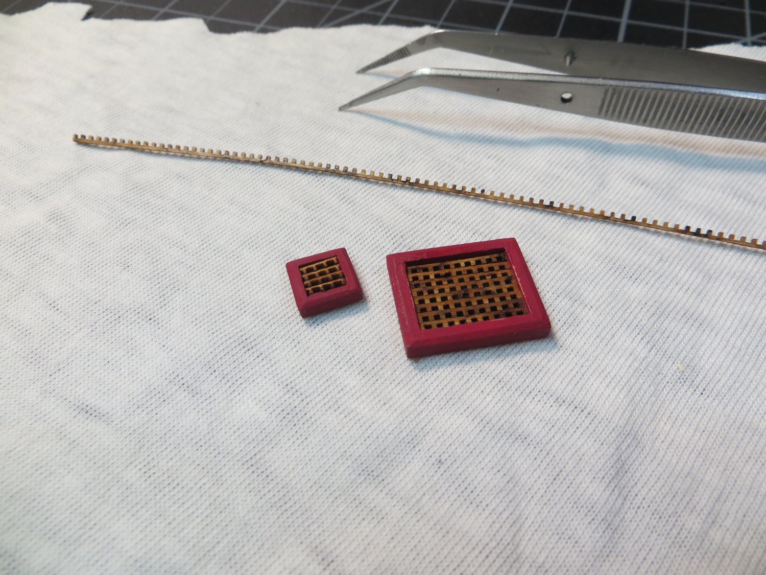
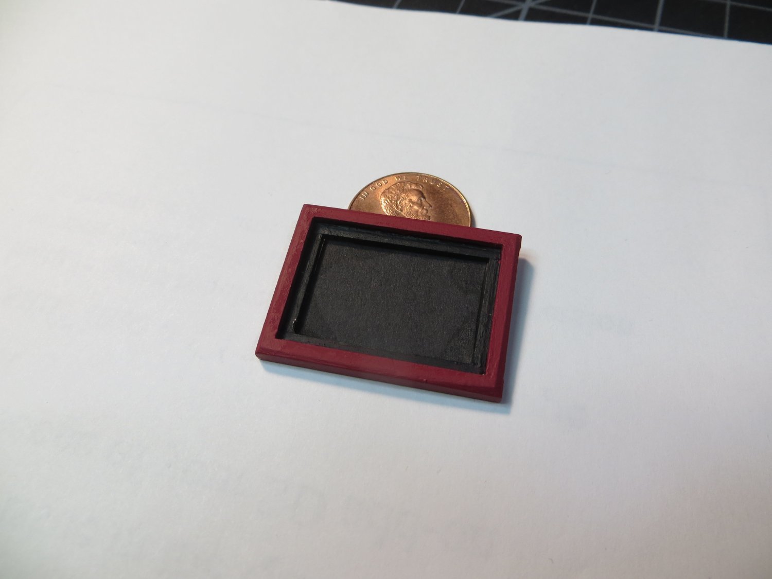
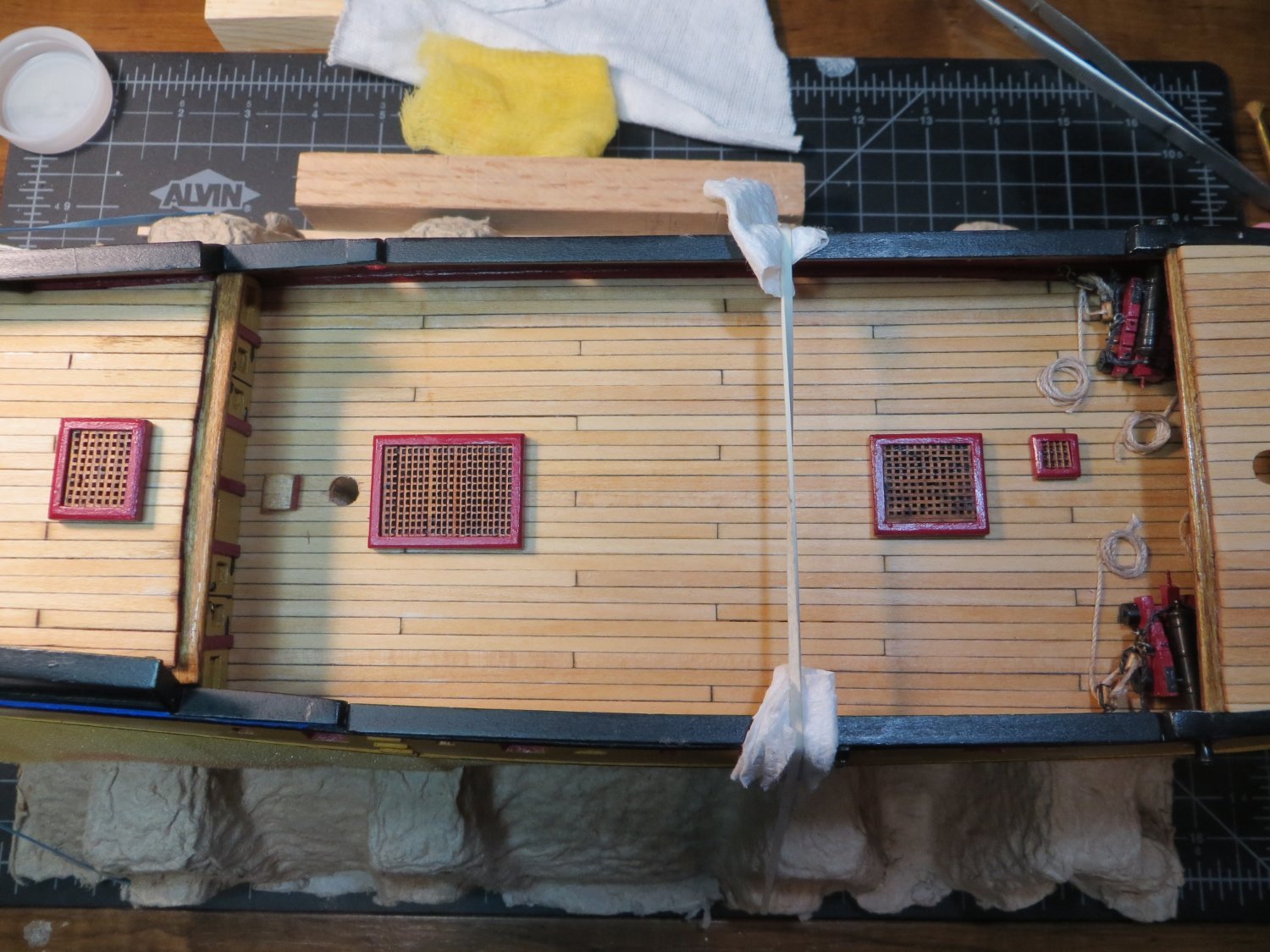
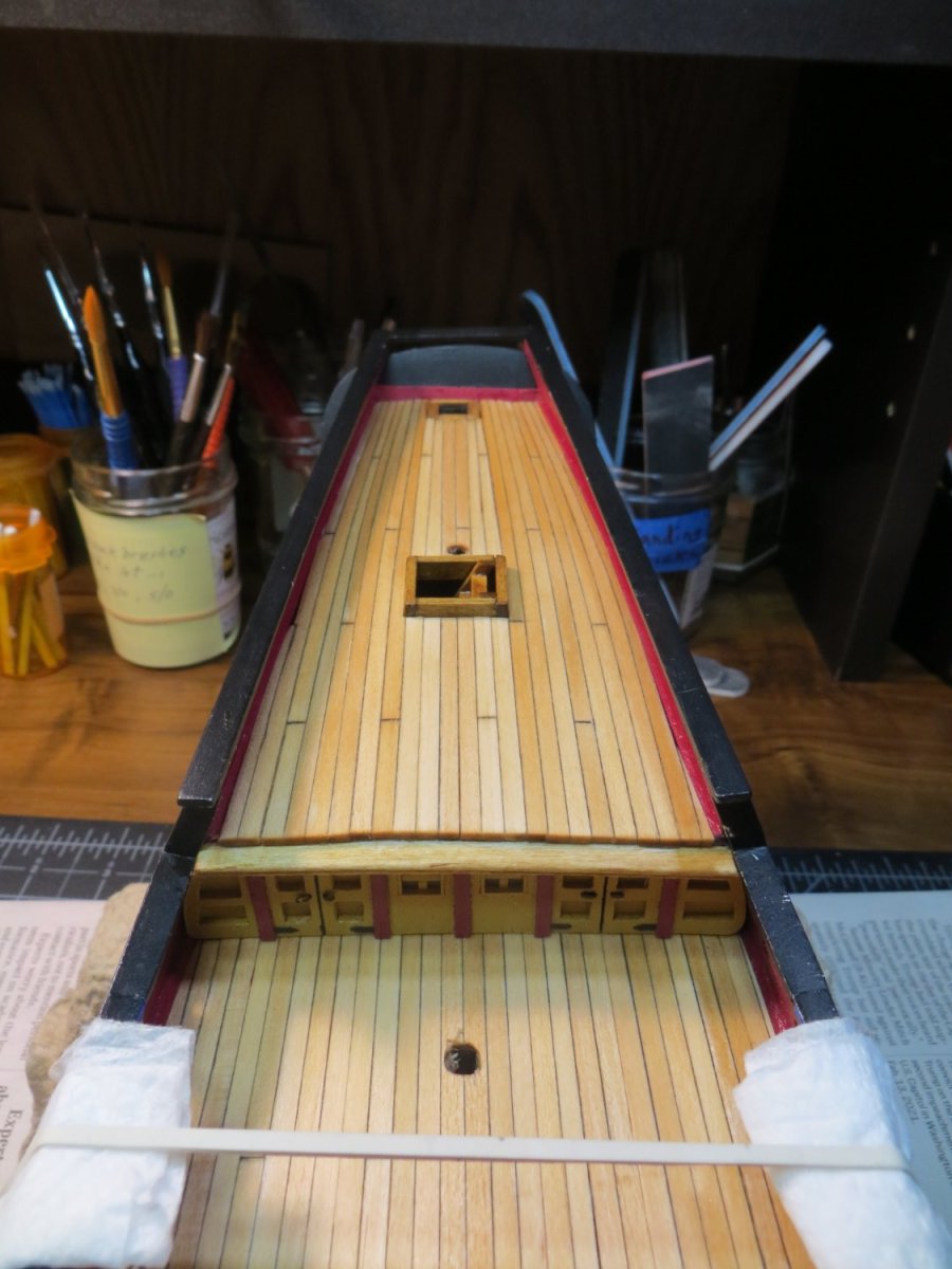
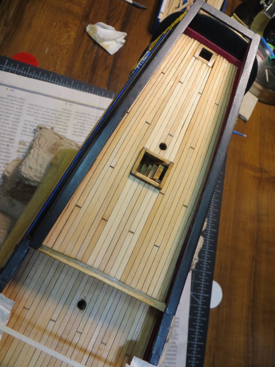
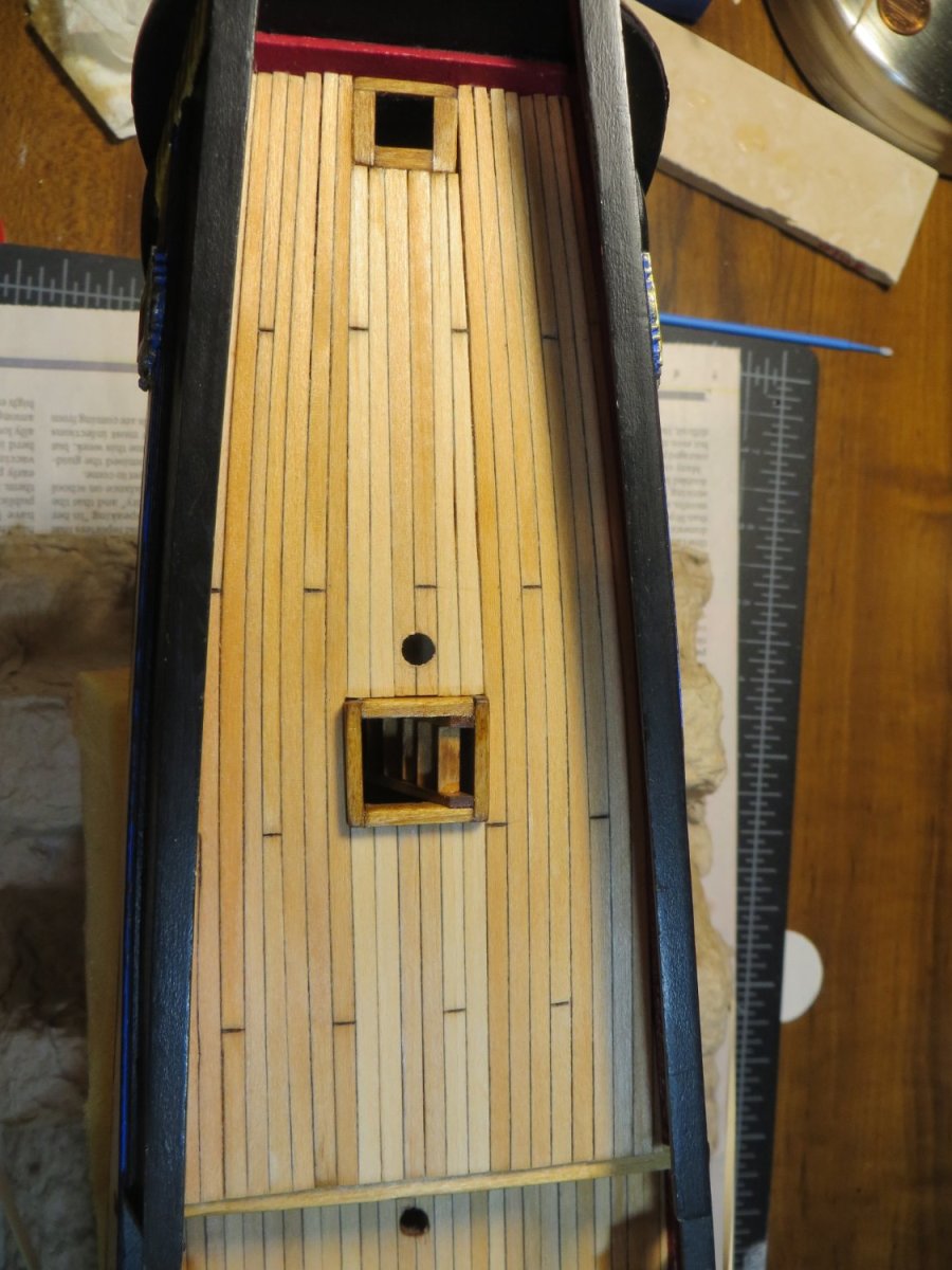
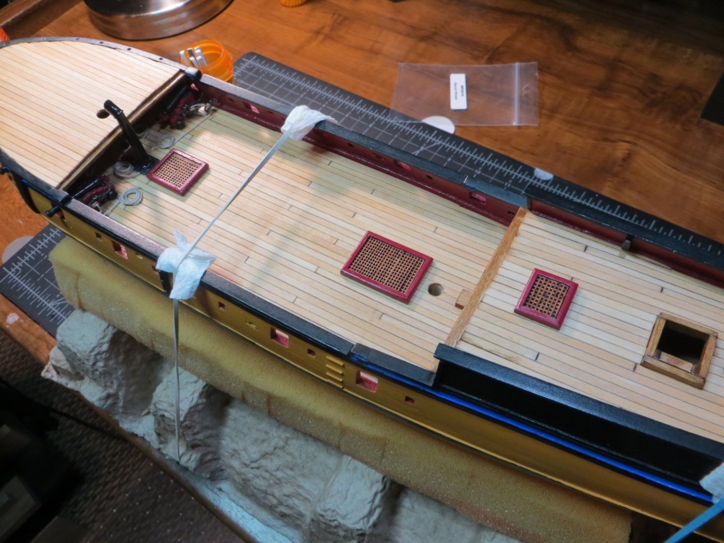
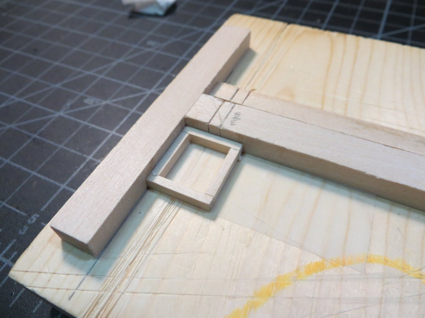
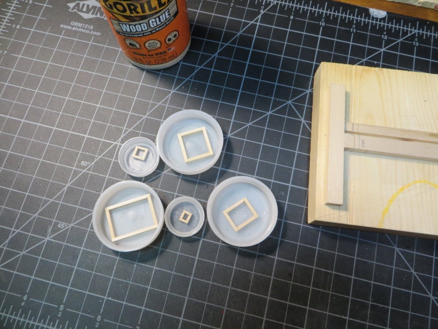
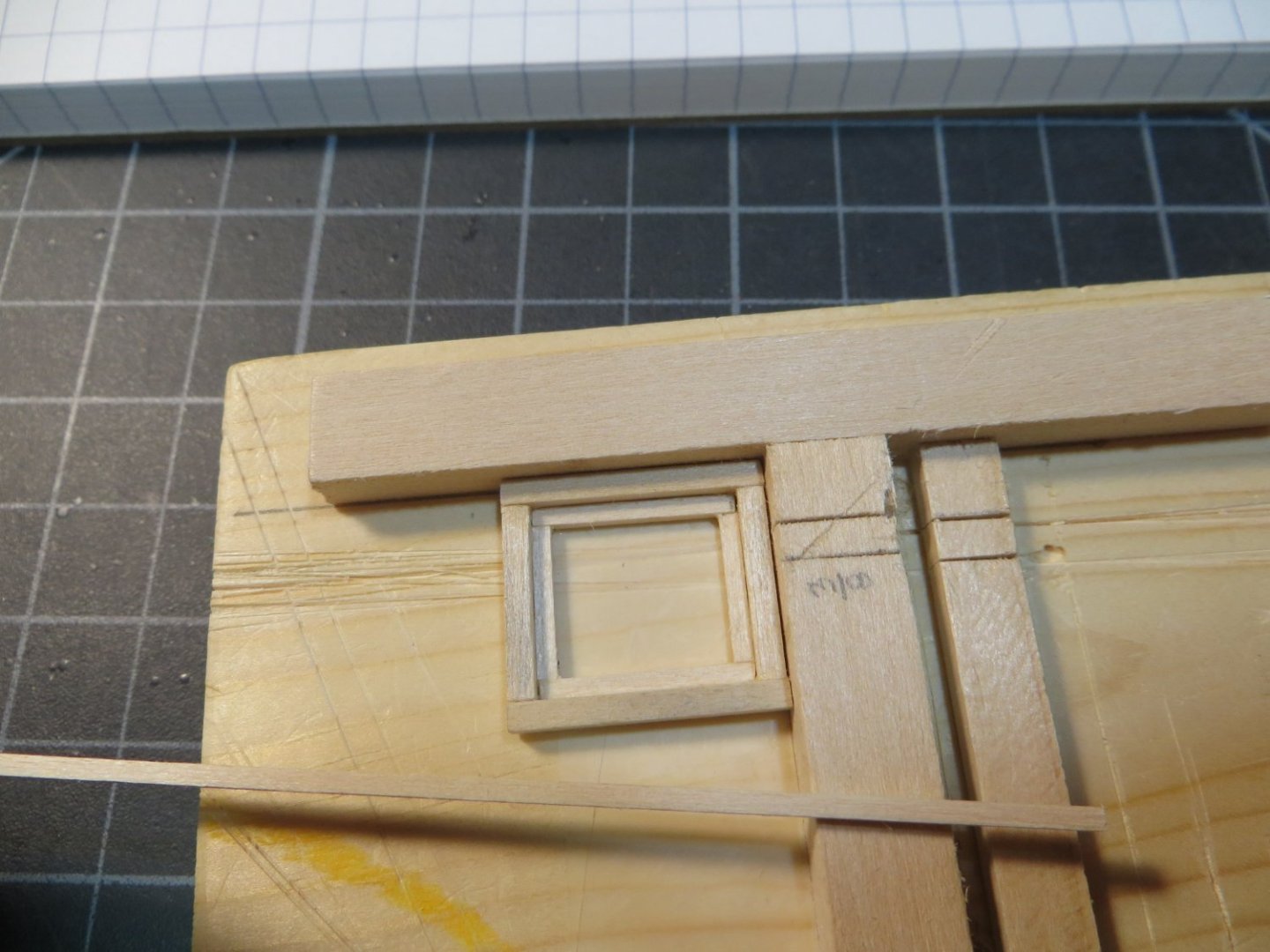
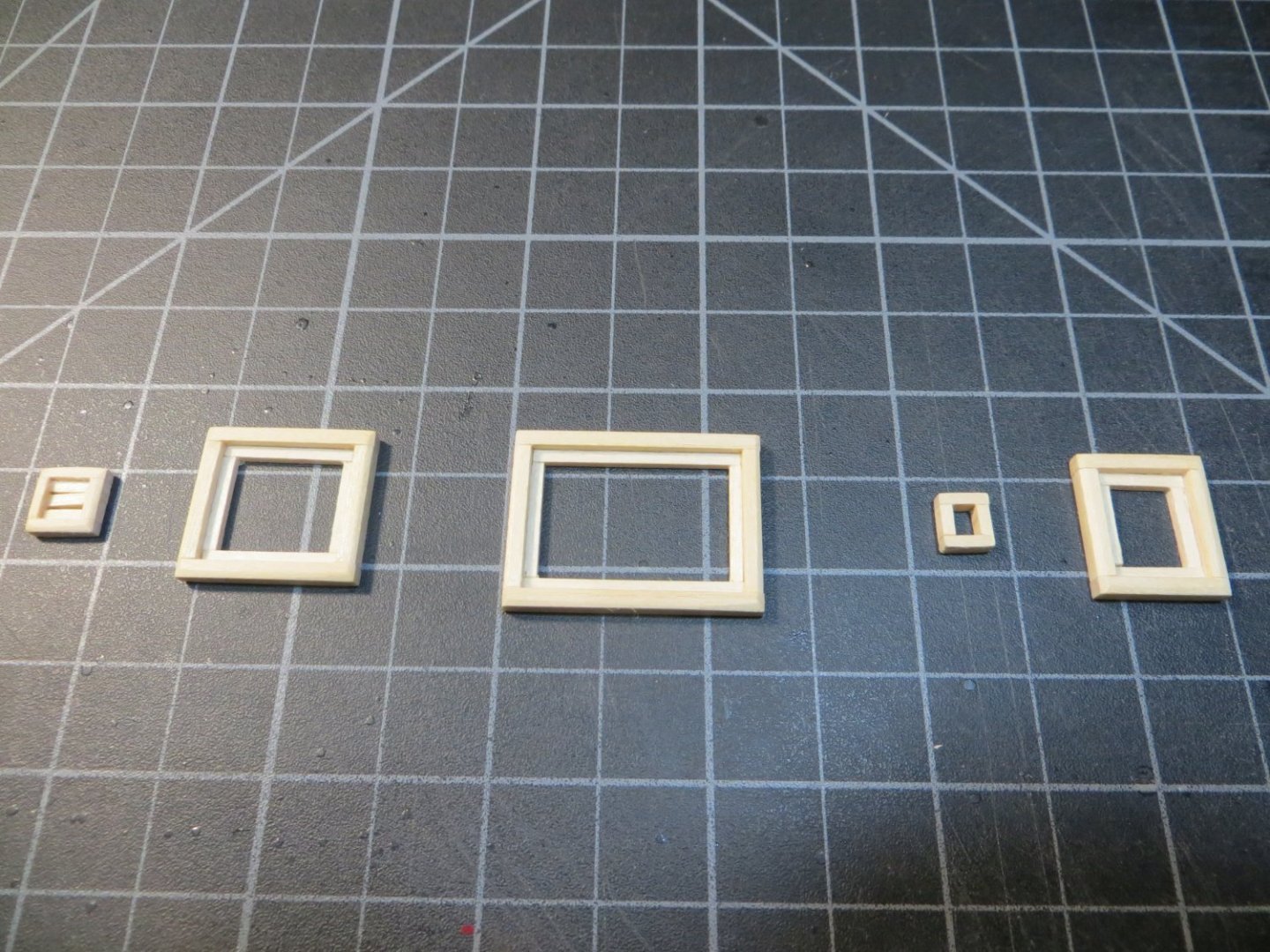
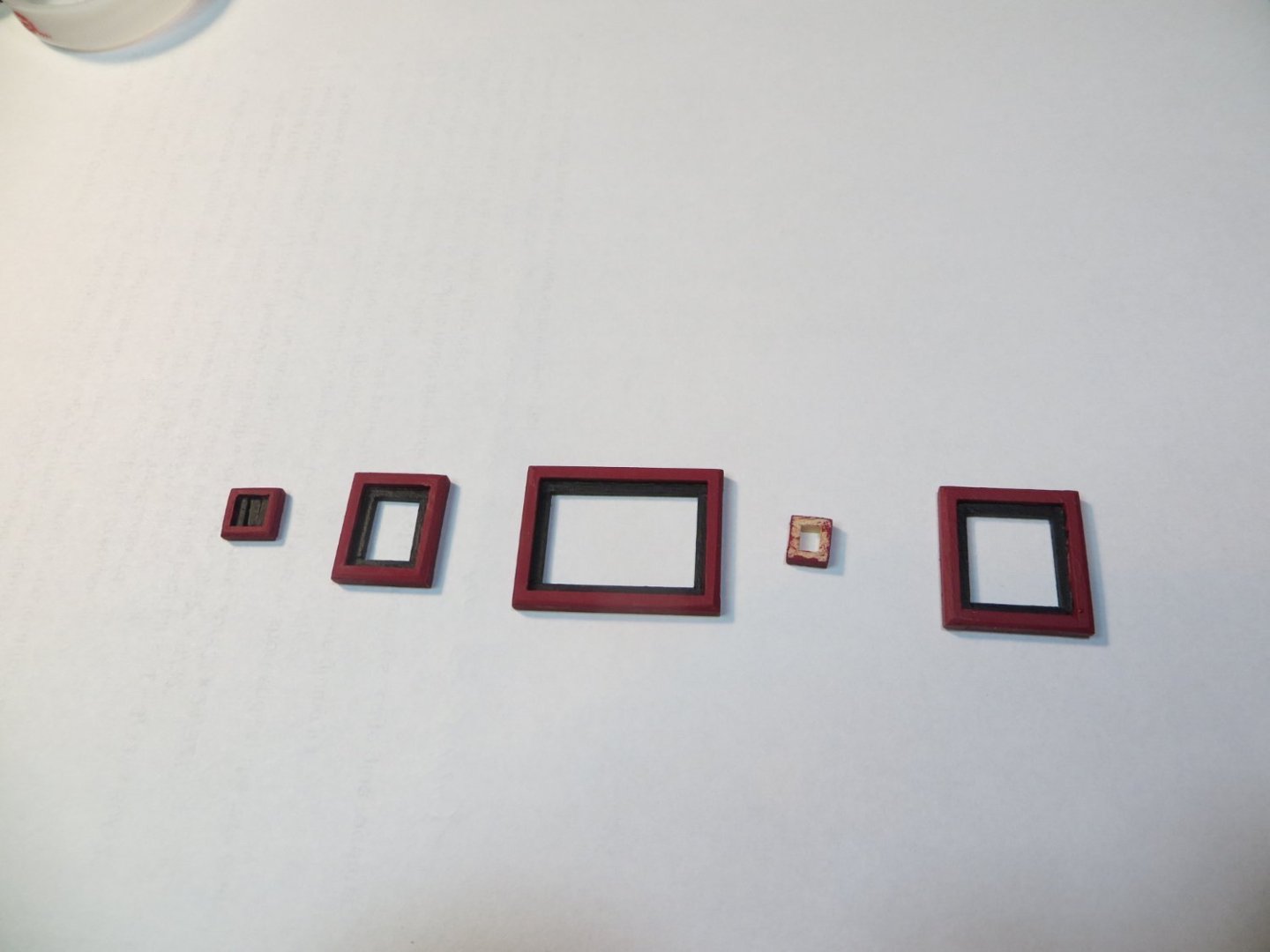
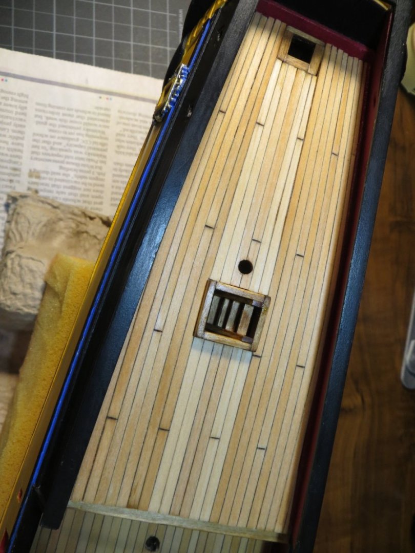
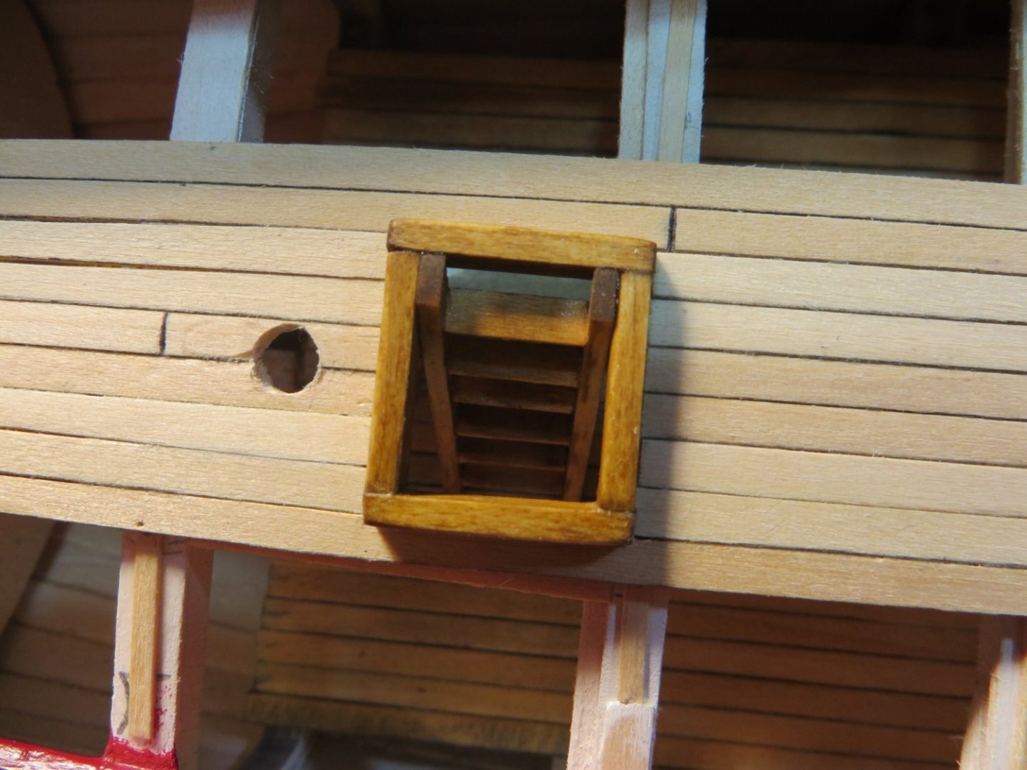
Hatches: Coamings & Gratings There are five Hatches with Coamings & Gratings on Rattlesnake. Back when I started planking the decks, I made a decision to glue the hatches on top of the deck, rather than building the deck around the hatches. I used 3/32”x1/8” stripwood for the large coamings. 1/16” x 3/32” stripwood for coamings #1 & #4. I sanded an angle on the top outside edge to smooth off the 90-degree edge. I painted the coamings red. The gratings in the kit are made of cherry wood. They will only be treated with wipe-on poly. Model Expo did not provide enough of the laser cut stripwood for the gratings. But, per my request t0hey sent me some extra at no charge. That’s a nice benefit with their models. Here is a list of the hatches starting at the bow and going aft. I did not add the one that goes under the Focsl deck. This space was mostly filled up with the fully rigged cannons. 1. Galley Steam Grating – located between the galley stack and the foremast. I used the smaller stripwood on this little grate. 2. 2nd Largest Grate – located aft of the Fore Gallows Bitts. It is nearly an inch long 3. Largest Grate – located forward of the main mast & aft of the long boat bitts. It is 1.25” long 4. Small Scuttle – located in front of the cabin wall. It has a solid cover 5. 3rd Largest Grate – located in front of the capstan on the quarter deck Here are the steps I used along with some pictures: Measure, cut & glue the outside frames according to the plans. I used this jig to make sure they had square corners. This important for the gratings to lay correctly. I used lap joints. I made all 5 at once, while I was on a roll. Measure and cut the inside ledges to hold the gratings. Use 1/16” square stripwood and made sure it was flush with the bottom of the coamings Sand down the outside top edge at an angle to smooth off the 90-degree edge Paint the coaming frames red. Paint the ledges black Cut and glue black cardboard under the gratings so it looks like the dark hold of the ship is underneath (instead of the lighter colored deck) Measure, cut with a #11 knife blade and sand the gratings to just fit the inside width of the coamings. Start at one end and lay the pieces in position. Place drops of CA glue around the outside edge to hold everything in place Cut a piece of 1/32” thick stripwood for the solid cover on the scuttle. Round the edges w/ a sanding stick. Stained the cover with Golden Oak Seal the assembled pieces with Minwax satin wipe-on poly. Mark the locations on the decks for each hatch. Glue them to the deck. I have not glued them down yet. They are only placed in position in the below picture. I'm going to wait until I make the Bitts before I start gluing. In fact, I may install the cannons before gluing the bitts. I want to have enough space to work on the cannons. It was challenging working under the focsl deck with those cannons! The next step is to make the Bitts. Thanks, Ed


-
Dave, I'm sorry to hear that you are starting over on your Half Hull build. It takes a dedicated modeller to start over when things aren't up to your standard. Thanks for the tip on the 280 grit buff. I just bought one based on your post. I too have had issues using the sanding drum on char. It is very difficult to control! Best of luck on build #2! Ed
-
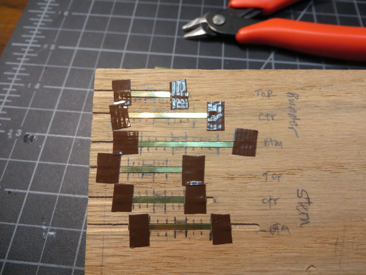
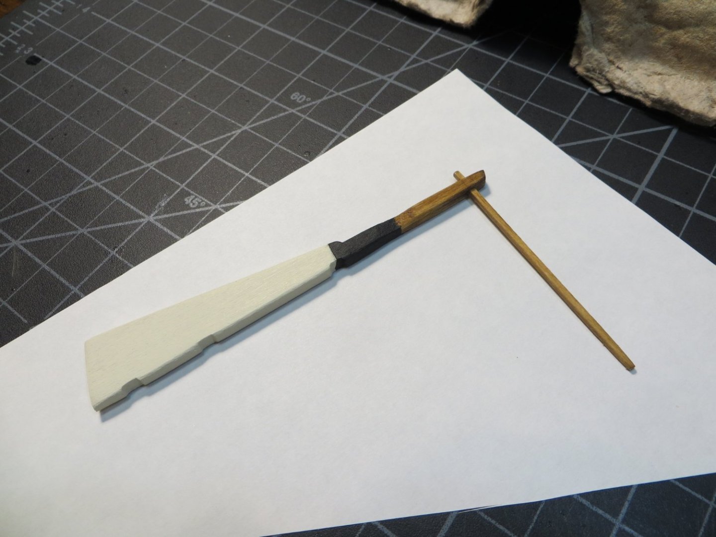
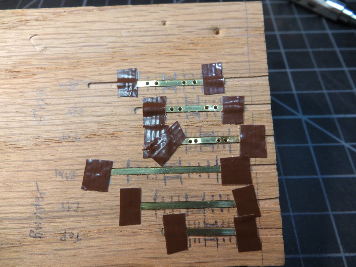
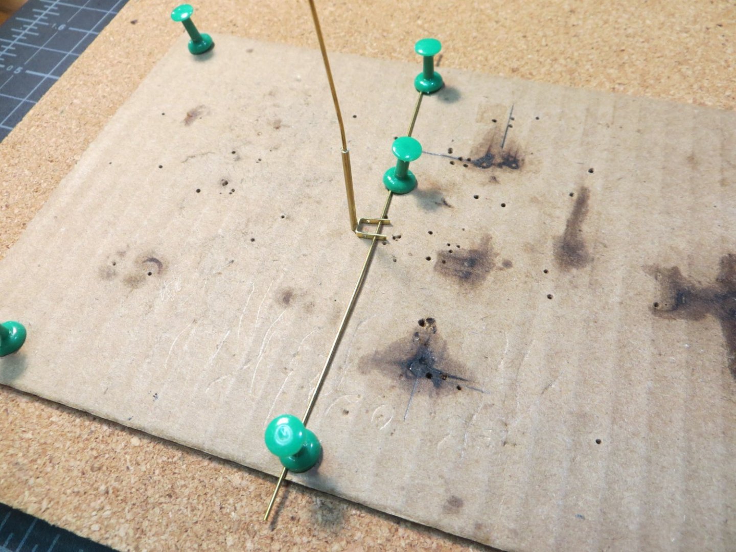
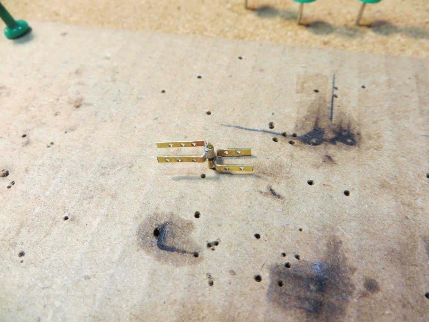
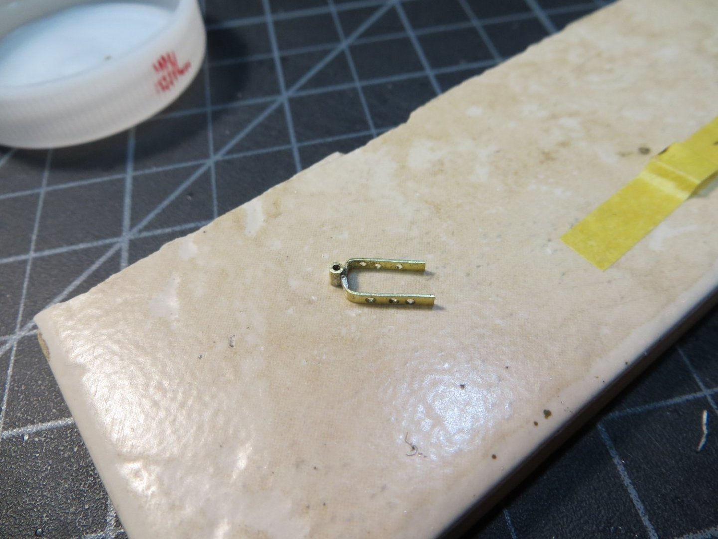
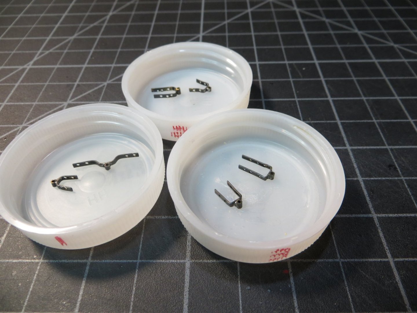
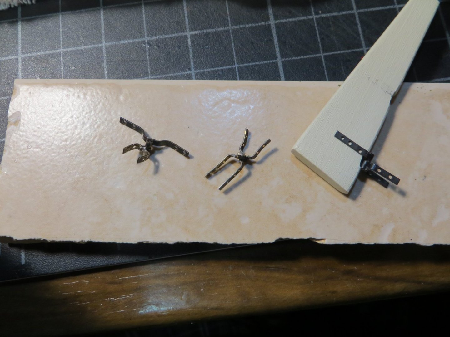
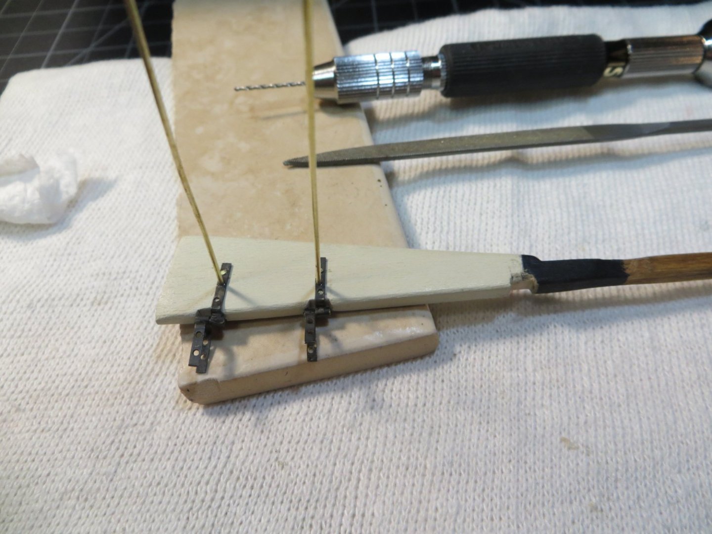
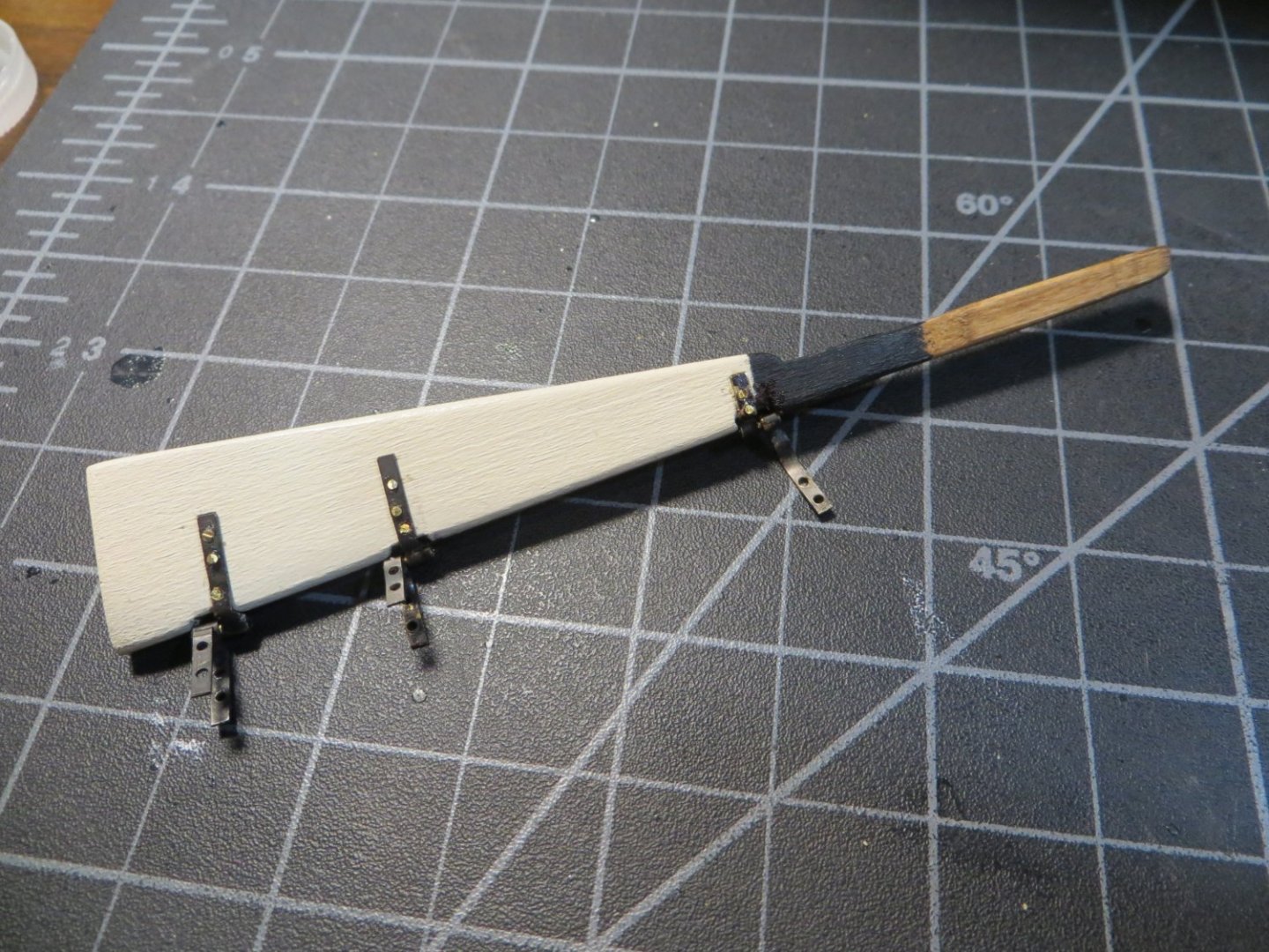
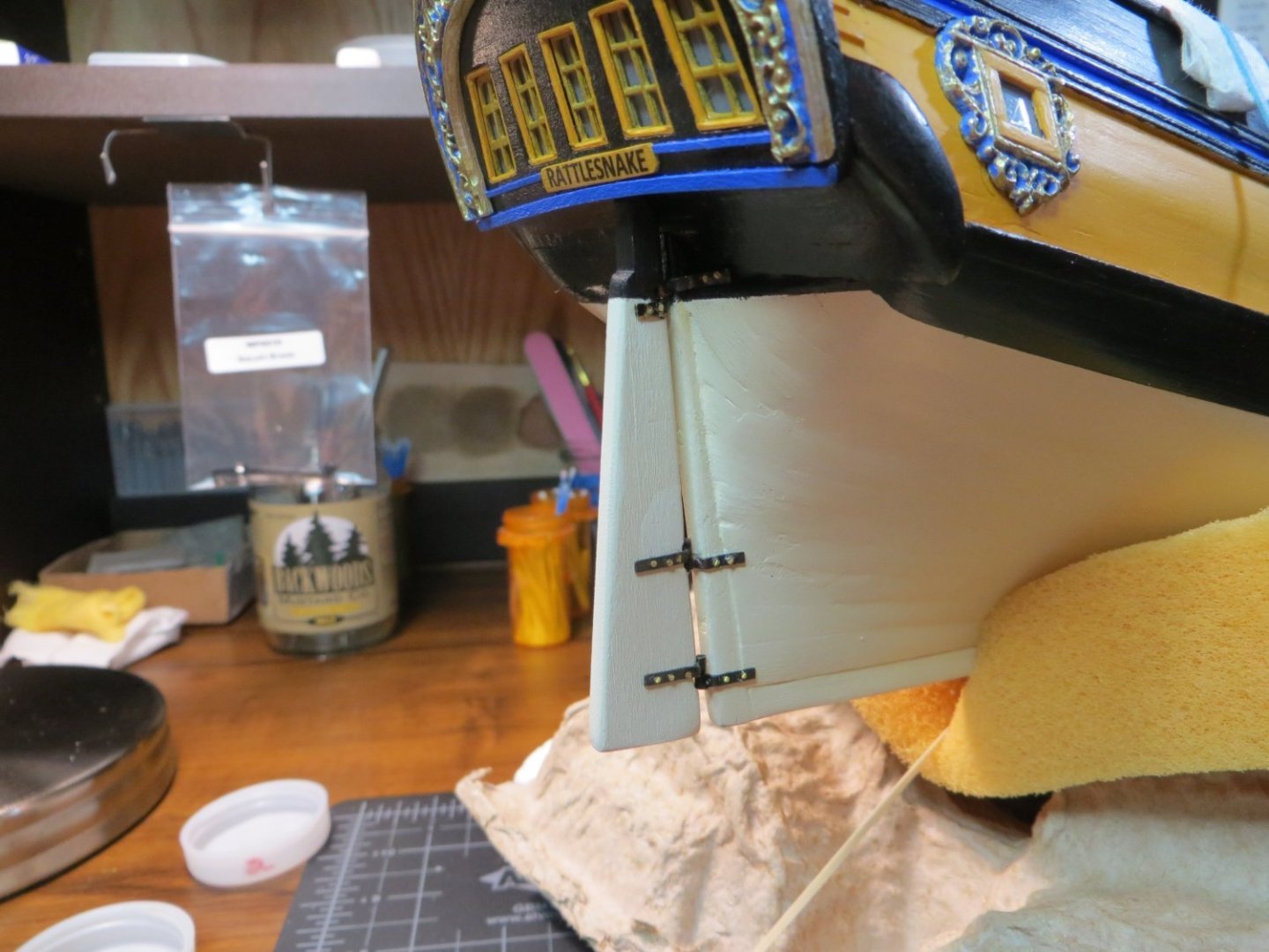
Rudder & Tiller The Rudder is provided as a laser cut part in the Rattlesnake kit. It requires clean-up to remove the laser char. The rudder must be tapered along the forward edge with no taper at the top to 5/32” from the middle to the bottom. I used a square piece of strip wood for the tiller. A hole is drilled in the top of the rudder stem to slide the tiller through. Do not glue the tiller to the rudder yet! You have to slip the rudder up through the hole at the stern before inserting the tiller into the hole. This is done as the last step. I did not bother to use any glue. It was a snug fit. I dry-fit the rudder and marked where the white and black painted sections of the hull cross the rudder. I hand painted both of these colors. I decided to stain the top of the rudder and the tiller with Golden Oak to match the coamings. Here it is afterward. The next step is to make the Pintles & Gudgeons hardware for attaching the rudder to the hull. The pintles are on the hull side and the gudgeons are on the rudder side. On my Bluenose build I made the rudder so the hinge was free and it could turn from side to side! Unlike Bluenose, the rudder stem goes all the way up to the deck. It does not turn much, unless you sand down the entire stem of the rudder. I used the brass strip that came with the kit to make this hardware. The process begins with meticulous measurements to identify where to drill the holes in the strips for attaching to the hull/rudder. I made a build board with shallow dado cuts to hold the strips while using the drill press to make the holes. Some people say they use rubber cement to hold the strips down. This did not work for me with Bluenose. Gorilla tape works pretty good. Brass strips ready for the drill press: The 3 strips for the Stern post with holes drilled using a #64 bit: After drilling the holes it’s time to bend the strips and solder 1/16” pieces of tubing to the middle of each one. I really struggle with soldering. The hardest part for me is holding the parts together, without them moving, while pushing the tip of the iron against the part and moving it out of position!!! Ahhh! Insert expletive! One of the parts ready for soldering. The problem with this setup is it’s hard to saw off the excess tubing close to the strip and without crushing the tube. I switched to cutting the tube before soldering after this: One of the brass strips and tubes assembled: Here is a completed piece of hardware with tubing soldered to both brass strips and a 0.032” rod inserted to connect the tubing. After installation on the ship, I placed a drop of CA glue in each tube: After all the parts were assembled, I treated them with brass blackening chemical. Here are the 3 sets ready to install: Dry fitting the parts on the rudder and stern: I used 0.032” brass rod to attach the pintles & gudgeons. I dipped the tip in thick CA glue, which squeezed out under the strip as well as in the hole. The excess rod was trimmed off tight to the part: Rudder attached. I touched up the paint after this picture. I still need to apply a coat of wipe-on poly for protection: Rudder stem with Tiller attached. I plan to add a couple of more coats of Golden Oak to darken the tiller: The finished view of the stern! The step I'm working on now is making the Hatches & Gratings. Thanks, Ed


-
Ed Ku20 reacted to a post in a topic:
Rattlesnake by Ed Ku20 - Model Shipways - 1:64
-
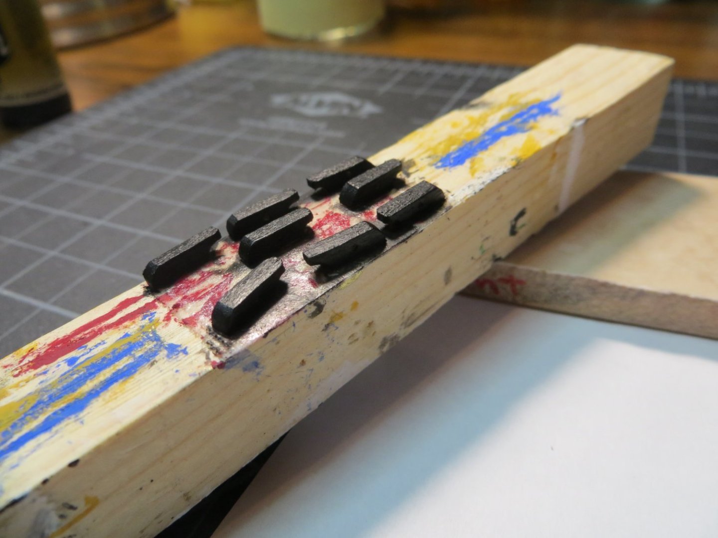
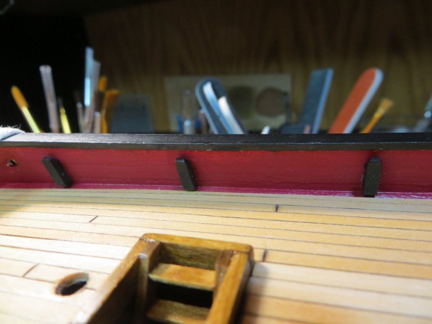
Make & Install 8 Kevels I have another quick update. The plans call for making 8 Kevels from stripwood. These are similar to the Chesstrees we attached to the outboard side of the hull bulwarks. Except they go on the inboard side of the bulwarks. 6 of them go on the quarter deck. 2 more kevels are attached to railing posts on the focsl. I made all of them now, but will not add the last 2 until the focsl railings is completed. Here is the process I used. I cut 8 pieces of stripwood from this 3/32” x 3/32” piece shown below I used one of my old jigs to hold down 4 of them down at one time while I sanded the curved bevel that is at the top of the kevel. I used these round files to do the job Since these are pretty hard to see on the inside of the bulwark, I decided not to insert a detailed sheave like on the Chesstree. I just drilled a hole in the side, which is suggested in the manual I rounded off the bottom edge and cleaned everything up with sanding sticks I used my double-faced taping stick to hold them down while I painted them black. The tape also keeps the glued edge clean for better adhesion Here are the 3 kevels glued in place on the port side of the quarter deck My next step is making the rudder & tiller and attaching it to the ship using Pintles & Gudgeons. Thanks, Ed

-
Ed Ku20 reacted to a post in a topic:
Rattlesnake by Ed Ku20 - Model Shipways - 1:64
-
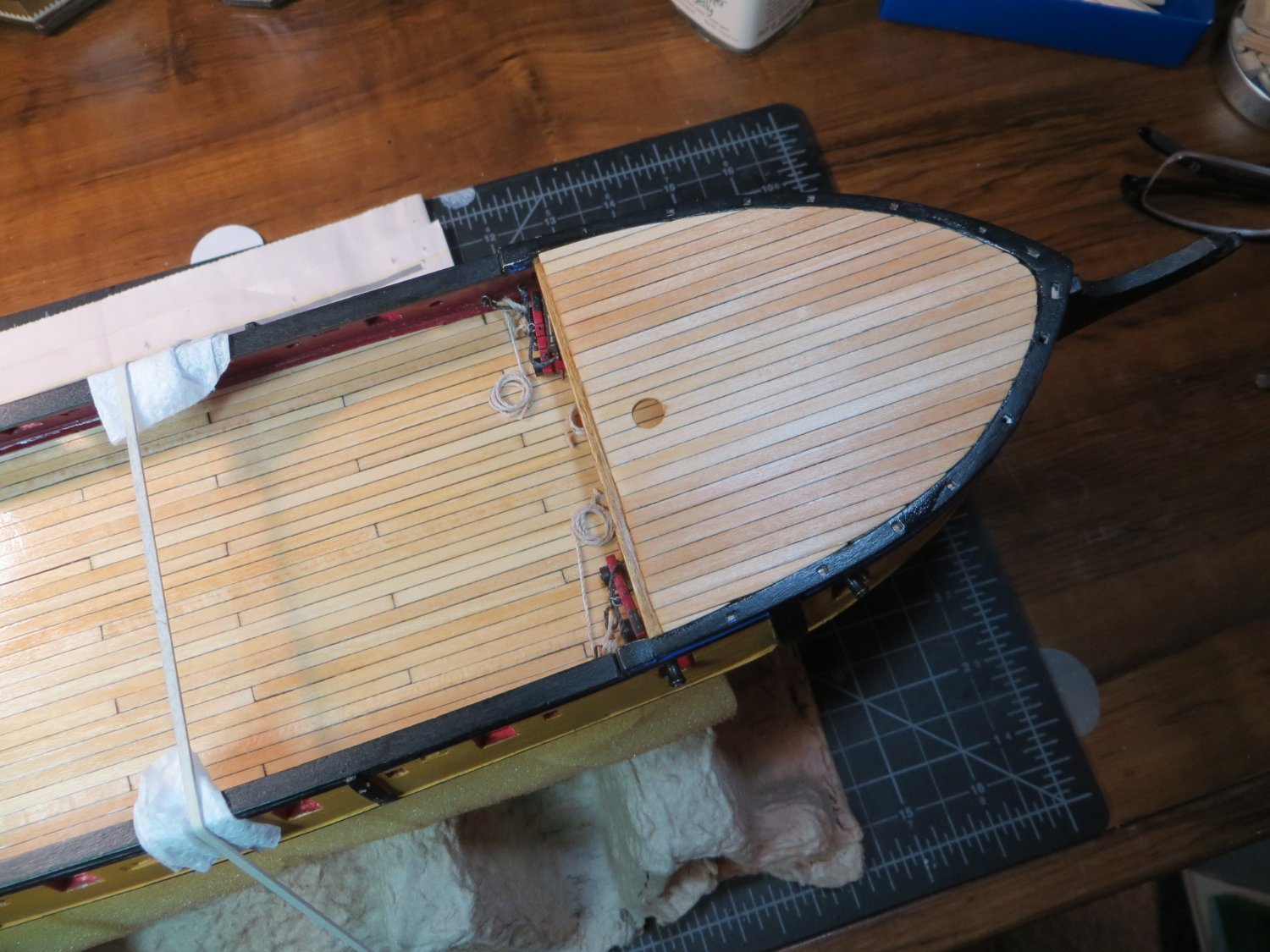
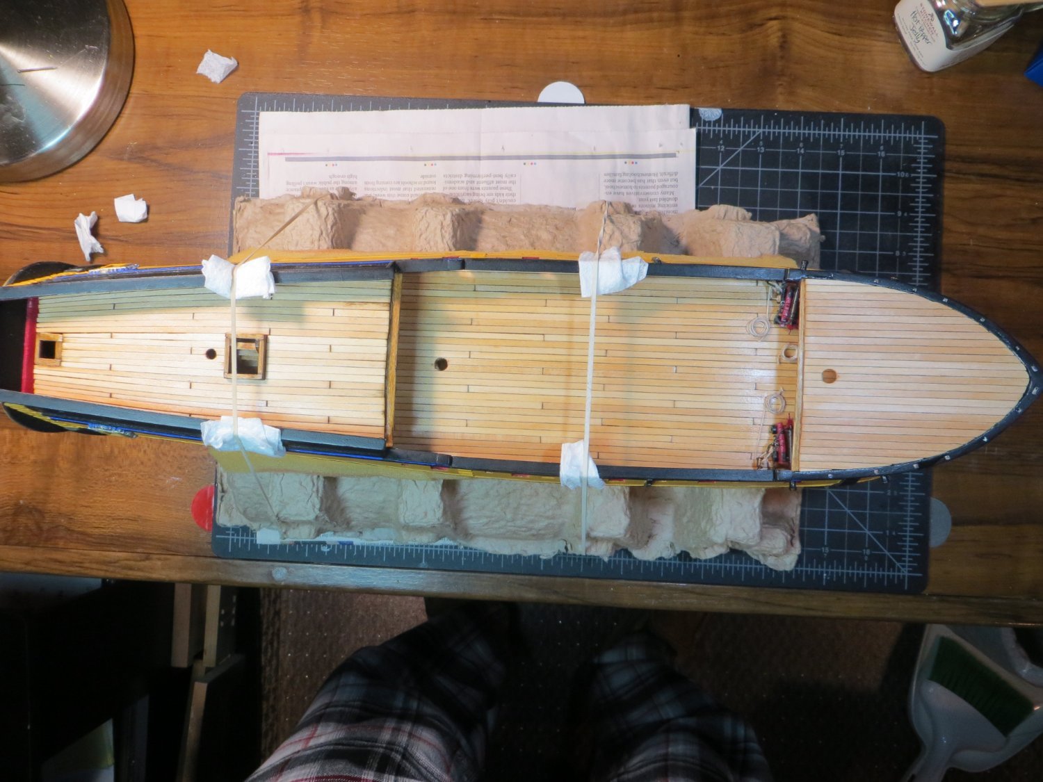
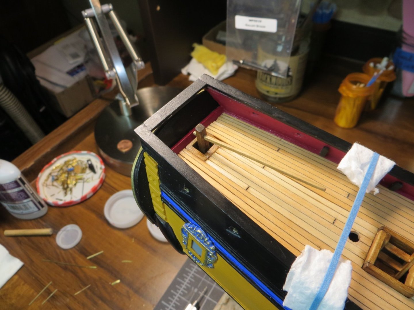
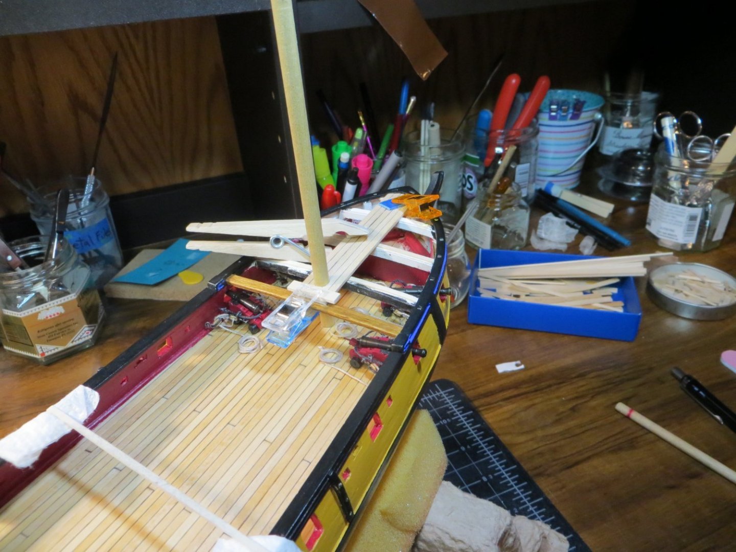
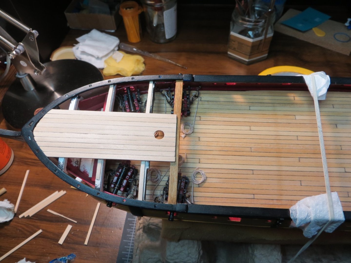
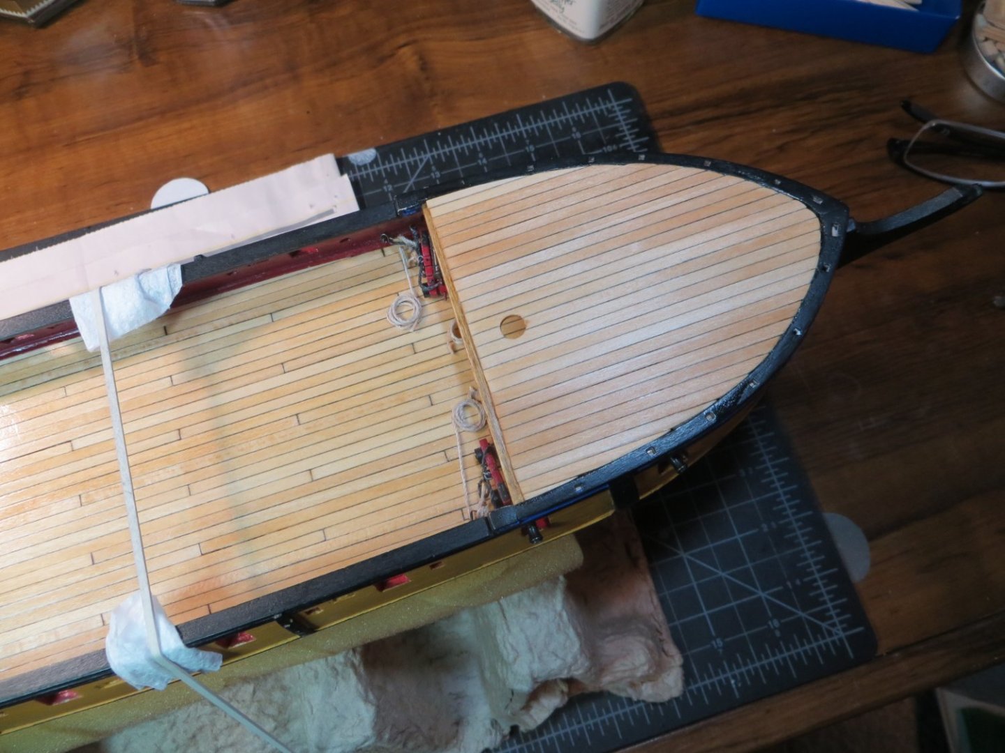
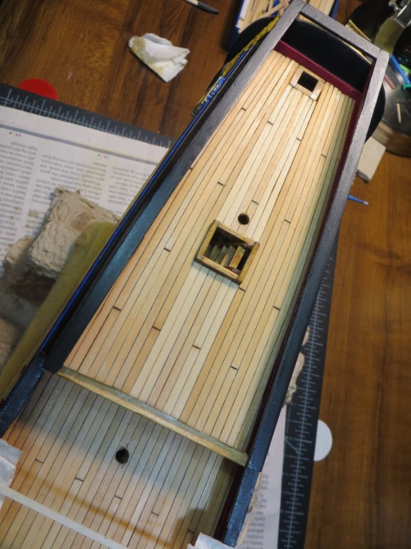
Planking the Focsl Deck Another milestone has been reached in the building of my Rattlesnake. The Focsl Deck planking has been completed. This means all the decks are finished! I had a couple of steps to complete before I started planking. · I was not happy with the original focsl deck beam. I painted it black a while ago and then decided to stain the quarter deck beam with Golden Oak. Now the black beam didn’t look so good! So, I removed the black beam and replaced it with a new one that I stained the same color as the q-deck. When I made the focsl beam a while back, I did not have the Artesena scrappers that I used on the q-deck beam. I used them to create the same fancy groove on the aft side. Now, both beams match. · Next, I drilled out the hole for the fore mast in the gun deck to the full ¼” size that it needs to be · I also added some supports at the bow to hold the planks up on that end Now planking commenced! I learned from my mistake with the mizzen mast holes. This time I cut a short stub of ¼” dowel. I edge glued 5 planks together that were sized to fit down the center of the focsl. I placed a round piece of double-faced tape on top of the mast stub. I pressed the section of deck on top of the mast so the tape stuck to the underside of the deck. This is the spot where I needed to drill the hole for the mast! This worked very well. Below is the section of deck dry-fitted in position with the mast stub not fully inserted into the gundeck hole I applied glue and used a longer piece of mast to keep everything aligned while the glue dried Since the focsl deck is shorter, no butt joints are needed. The planking continues. My wife couldn't understand why I spent so much time building cannons that no one would be able to see! The finished deck after staining with Minwax Natural A birds-eye view of all the decks when finished Next step is making and installing the 8 Kevels that go on the inboard bulwarks. Thanks for looking in! Ed


-
Hey John, Best of luck with your move. Hopefully everything goes smoothly and quickly for you! Make sure the rental has room for your workshop!
-
Ed Ku20 reacted to a post in a topic:
Rattlesnake by Ed Ku20 - Model Shipways - 1:64
-
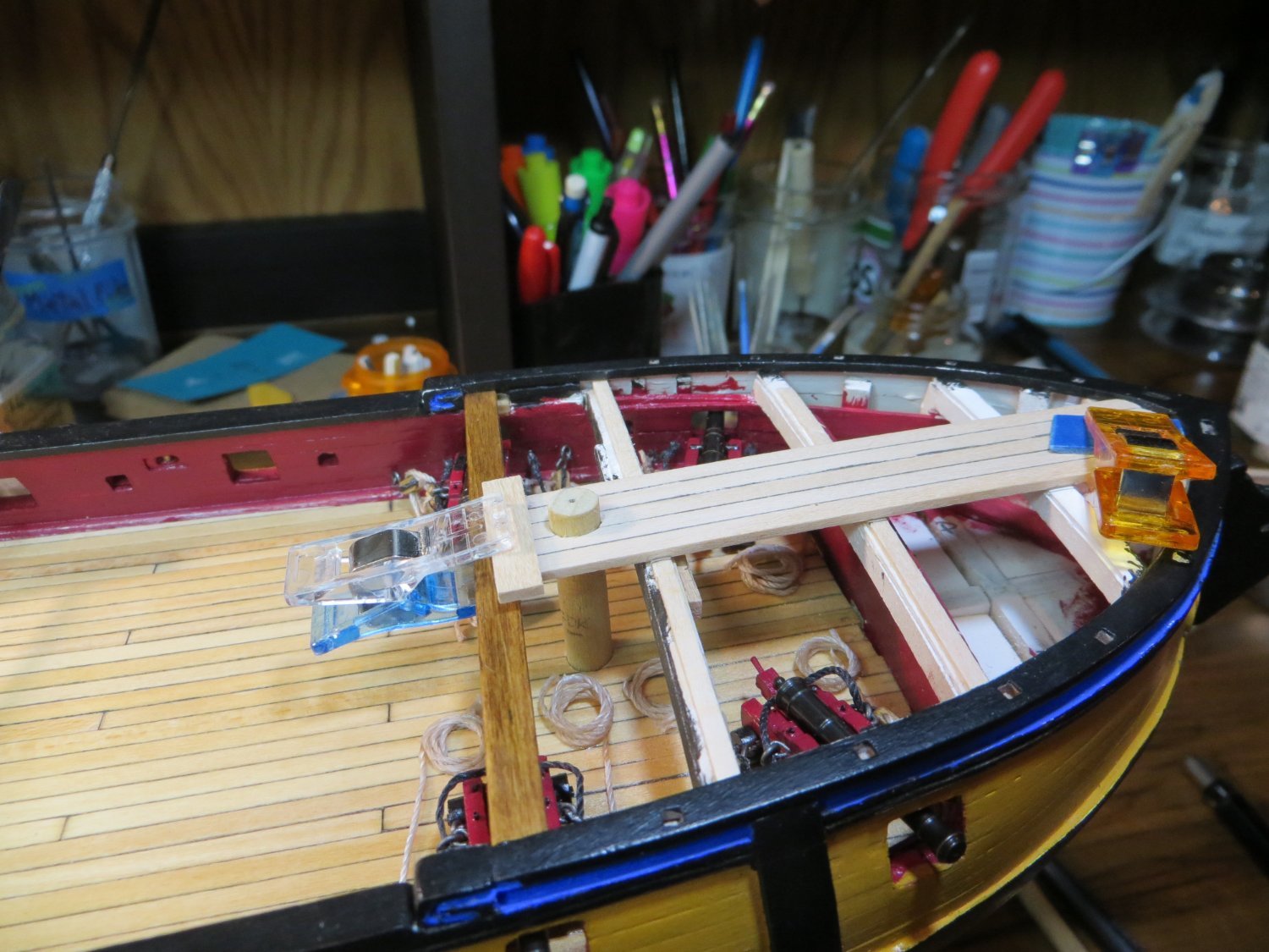
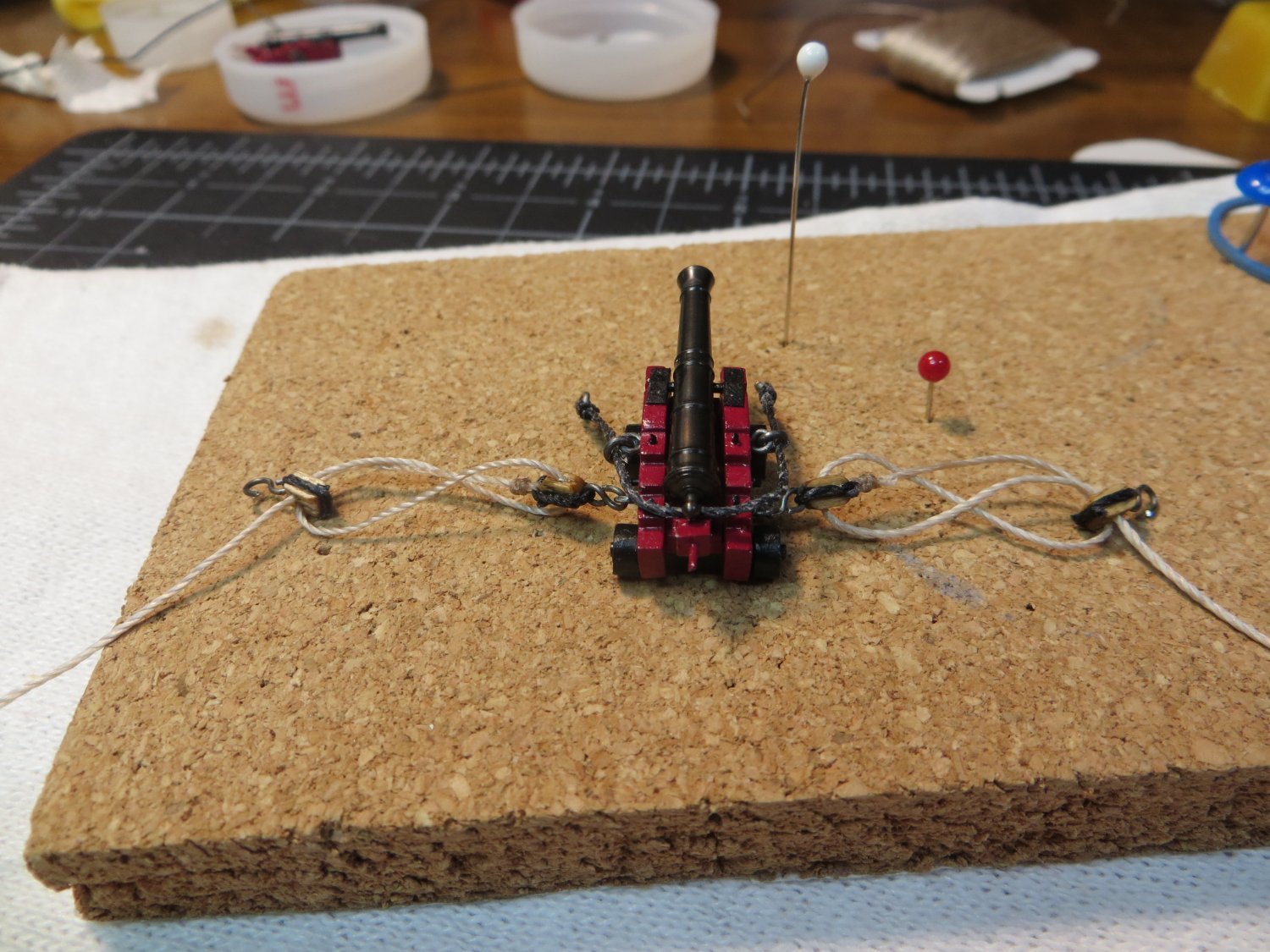
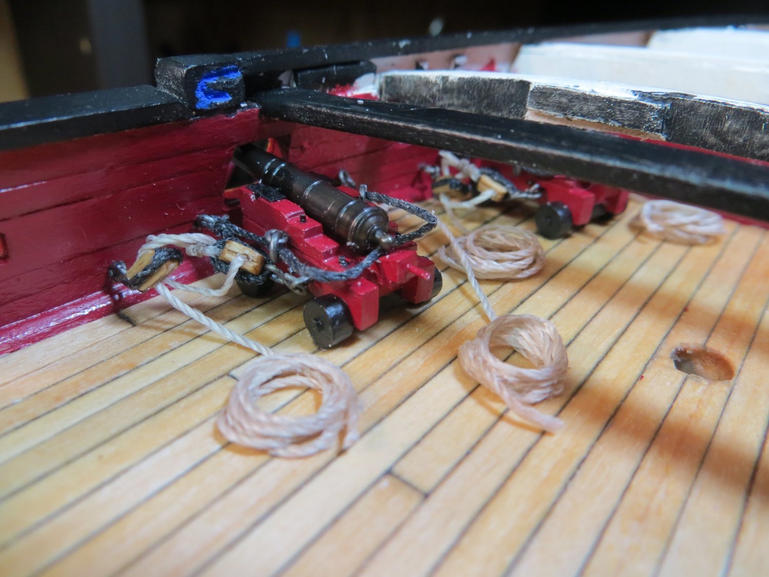
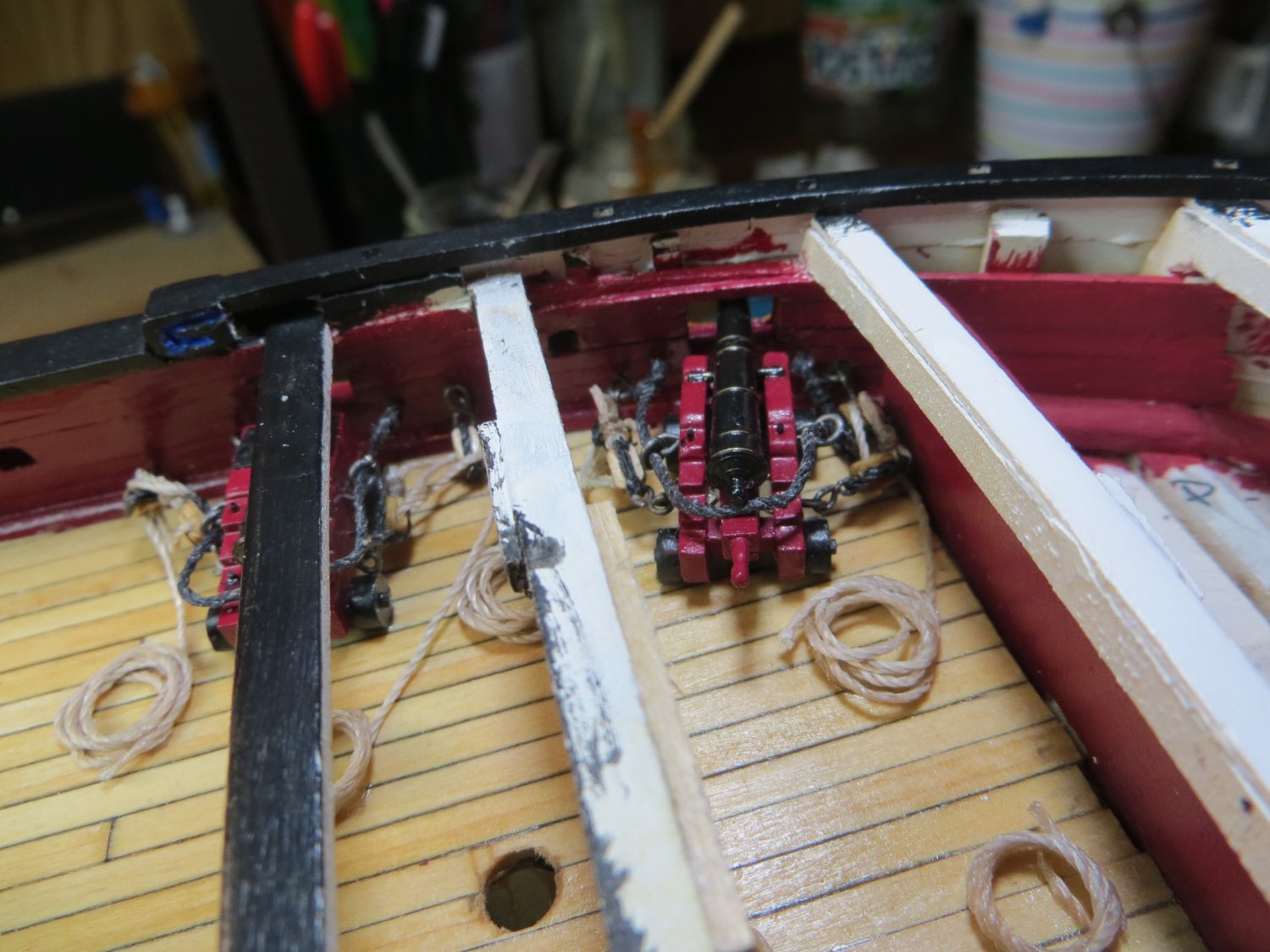
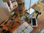
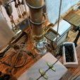
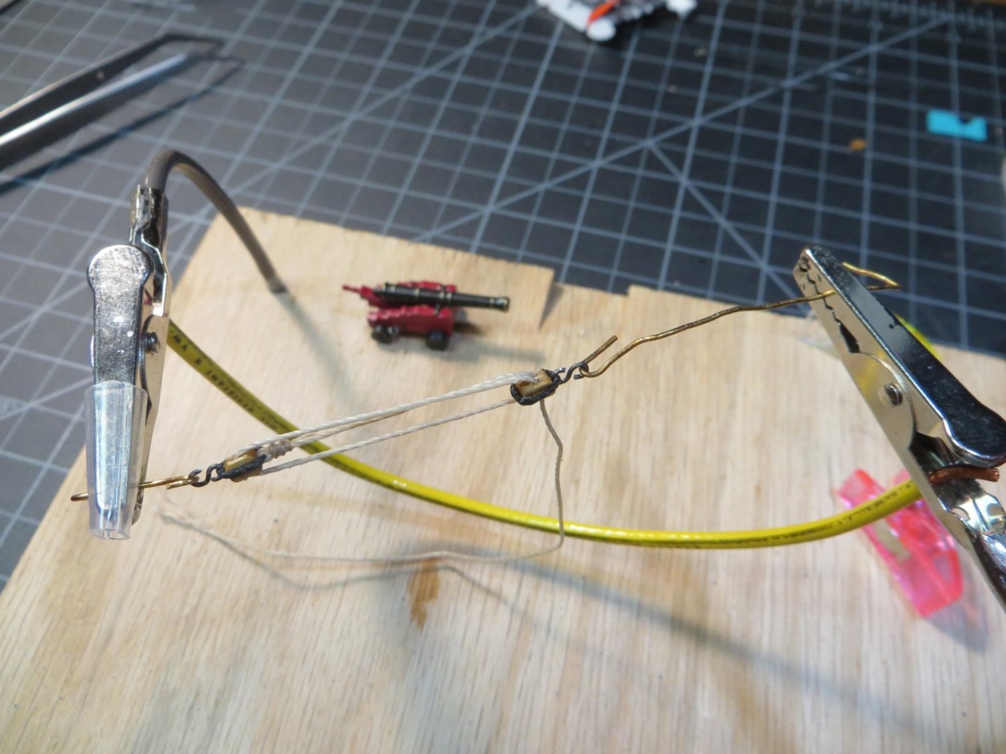
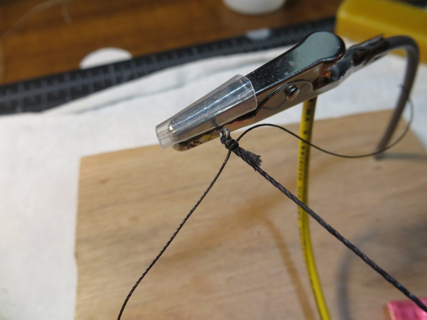
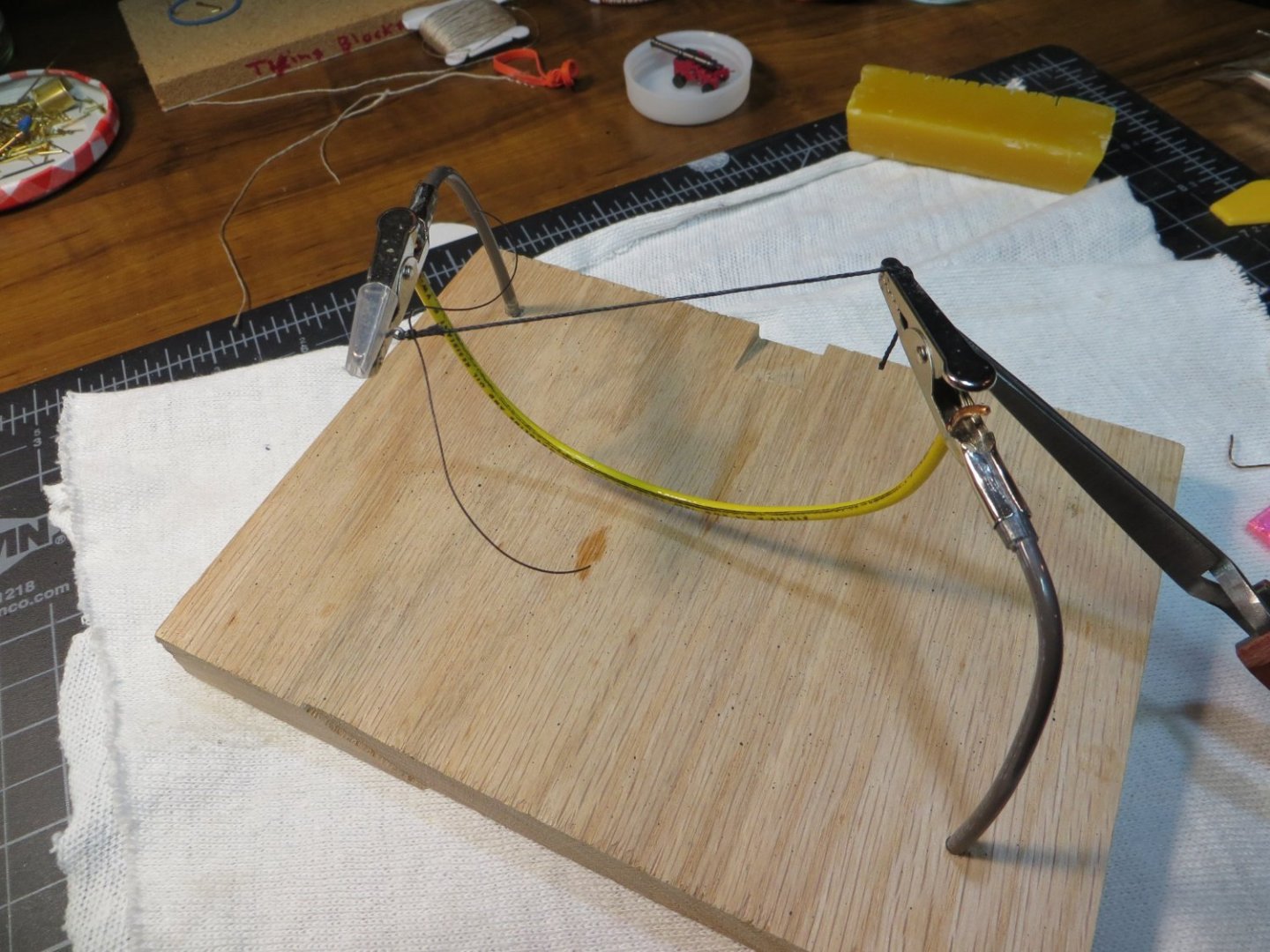
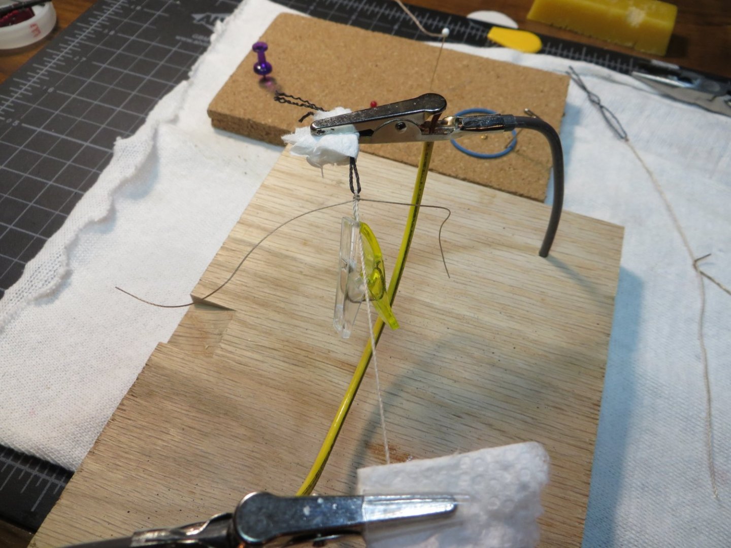
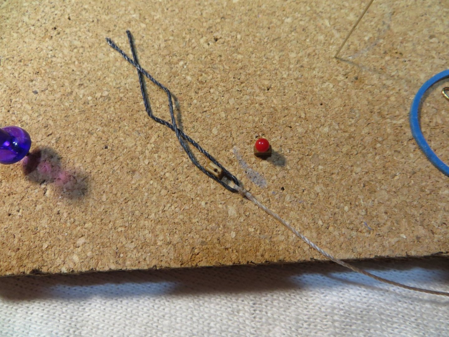
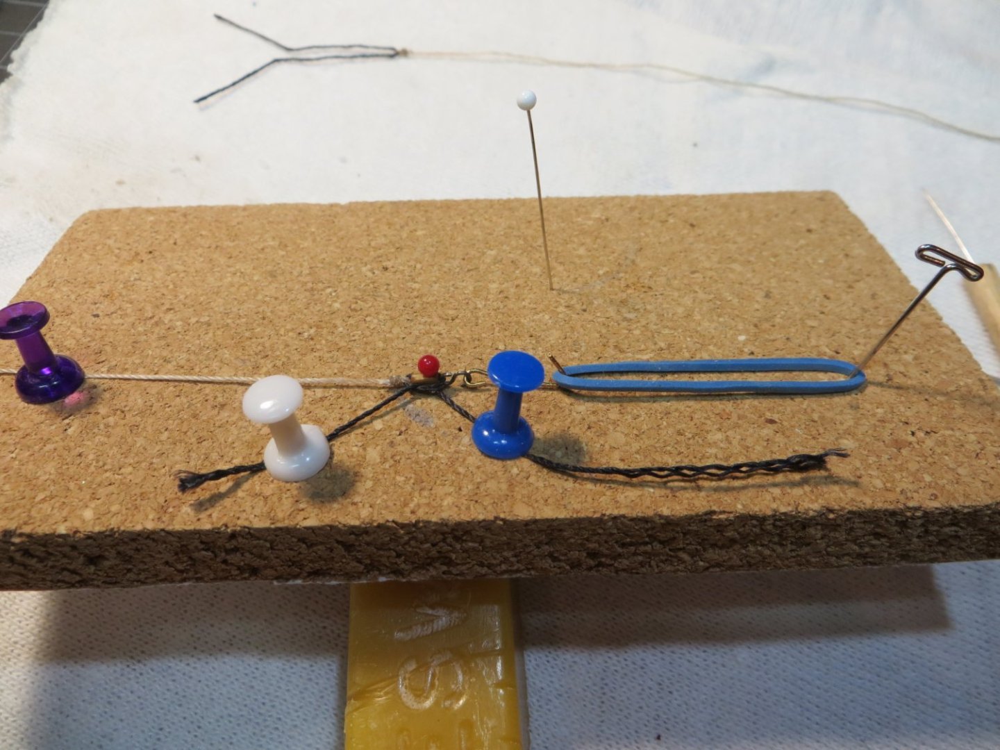
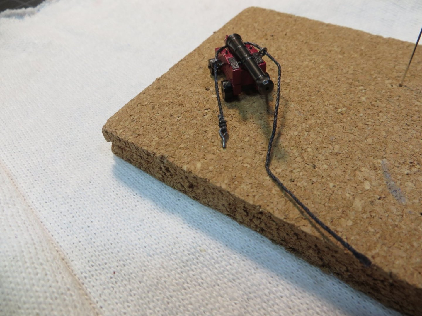
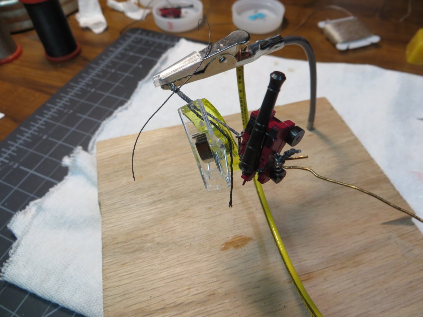
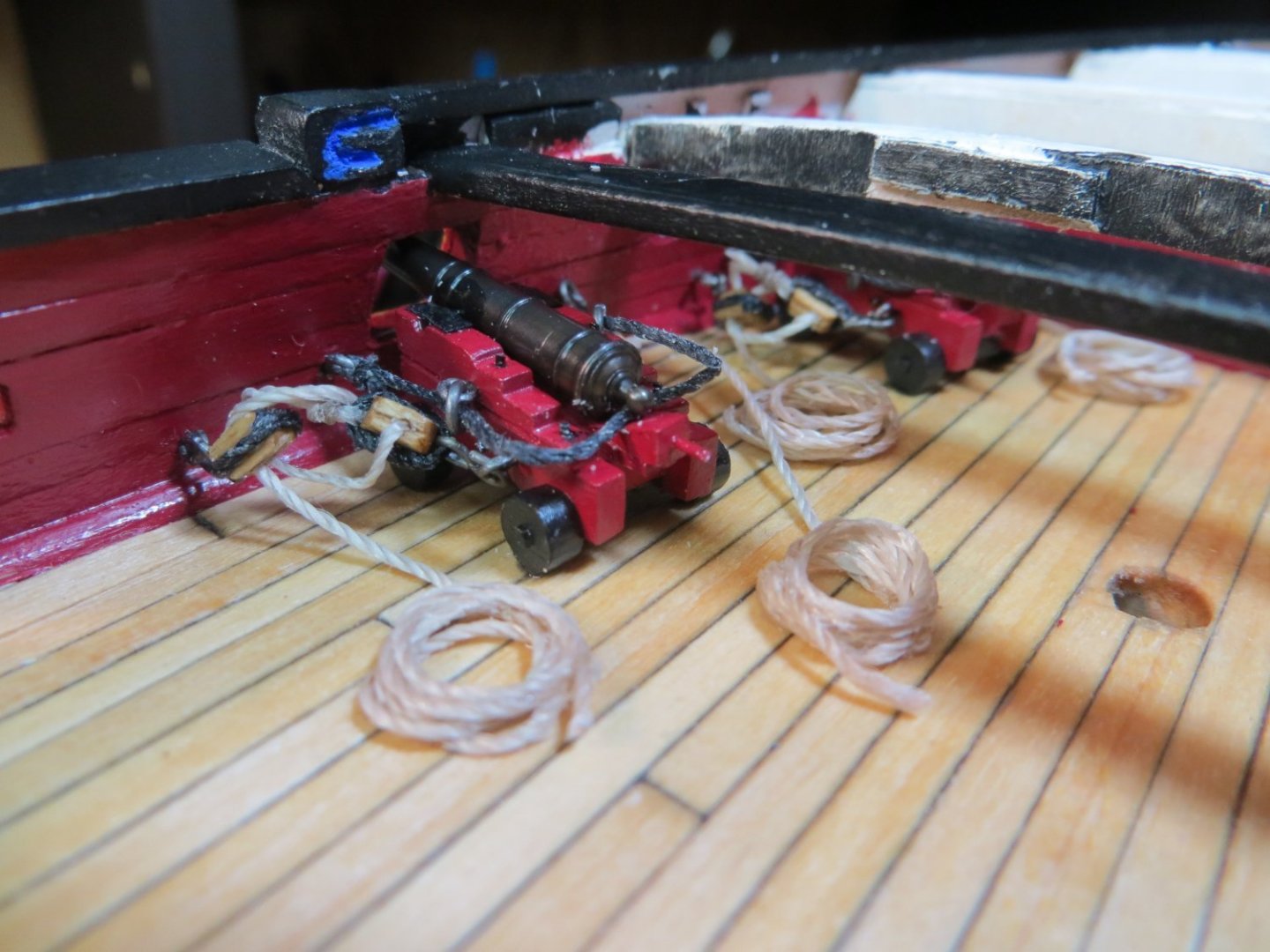
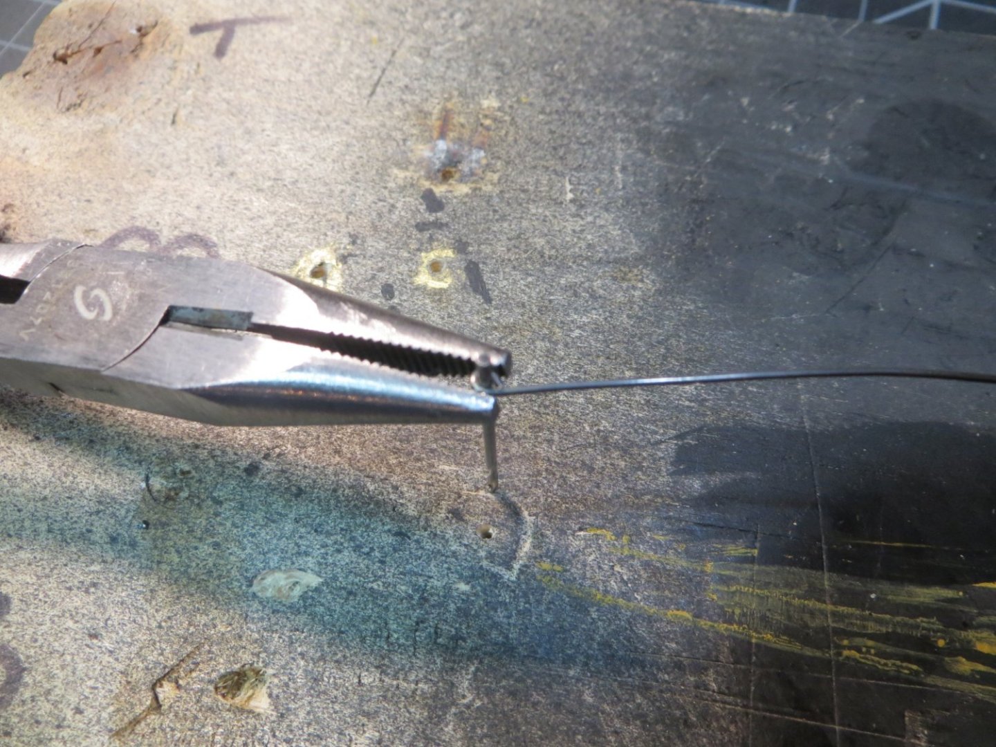
Rigging and Installing the Cannons on the Gundeck The next step is to add the rigging lines and install the cannons on the deck. There are 3 types of rigging lines on each cannon. (a) The Breech line limits the recoil of the cannon after firing (b) The Outhaul tackles are used to pull the cannon barrel into the gunport for firing (c) The Inhaul tackle is used to pull the cannon away from the gunport for loading. I decided I was only going to install the breech lines and outhaul tackles on my model. The inhaul tackles seem to clutter the deck in the models I’ve looked at that had them. Here are the steps that I used. Rigging the Breech Line – the breech line only requires an eyebolt to be seized to each end of the line. I dry fit the first cannon in the gunport to determine the proper length of line needed. I used the thicker 0.028” line. I used black line because I feel like the Breech serves more like standing rigging than running rigging. The eyebolt was seized with black thread off the cannon. Before seizing the eyebolt on the other side, it has to be threaded through the ring on the carriage, around the back of the cannon and through the ring on the opposite side. I used my homemade Helping Hands jig for seizing. I let the cannon hang in the jig while seizing the second eyebolt. Seizing the first eyebolt in the helping hands jig Breech line with 1 eyebolt threaded around the cannon carriage Seizing the 2nd eyebolt with cannon in the jig! Breech line completed Rigging the Outhaul Tackles – this rig is more complex. I used a 1/8” single sheave and double sheave block with tan 0.021” rope. The single block requires an S-hook to be stropped on one end. The seized loop of the tackle rope is stropped to the other end of the single block. The double block only needs an S-hook stropped to one end. These pieces are hooked onto the helping hands for threading the line in the blocks. Seizing the black “stropping” line to the tan tackle rigging line Single block and strop line with rigging ready for assembly on my cork block tying jig Everything tied down on the jig. A couple of drops of CA glue are used to hold the knot and secure it to the block. Completed rigging ready for threading the lines Threading the lines through the blocks using the helping hands jig All lines attached to the cannon carriage and ready to install on the deck Installing the Cannons on the Gundeck – this is without a doubt the hardest part of this entire process! The space is really tight and made tighter by having to work around the focsl deck supports! I used a fine punch to make pilot holes where the eyebolts need to be positioned on the gunwale. I used the pin vise to make the holes. Be careful you don’t go through the outer hull! I attached the eyebolts for the tackles with some thick type CA on the end to hold them in place. I found the best method was to attach the forward side rigging first. First the breech line, then connect the S-hook for the tackle to its eyebolt. Carefully squeeze the loop closed. Then I did the aft side. Once everything was set, I used CA glue on the rear trucks to hold it in place on the deck. I made rope coils separately. I tried several methods for making them. I had the best luck with simply wrapping the tan line around a smooth pen barrel. Then I used dilute PVA and rubbed it around on the line with my fingers (what a mess!). I let it partially dry then laid it under a magnet to flatten it out. I wanted these ropes to have the look of laying in loose coils. I glued the rope end coming off the tackles to the deck. The coil was laid on top of the rope end using the thick type CA. Here are a couple of pics of the finished product. I’m glad these will be hidden under the focsl deck! I got better with each cannon. I think the rest of the cannons will be easier with more open space to work with. I hope my notes are useful to you when you are installing your cannons. I still have 1 more cannon left to install. Then I will be ready to plank the focsl deck. Thanks, Ed


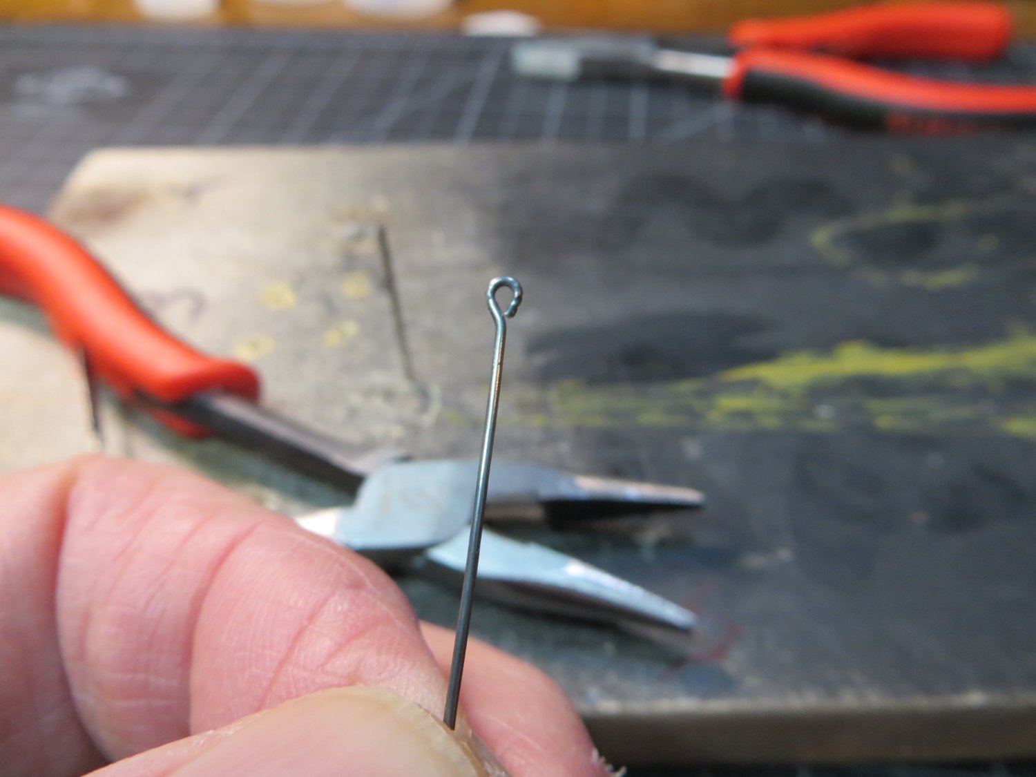
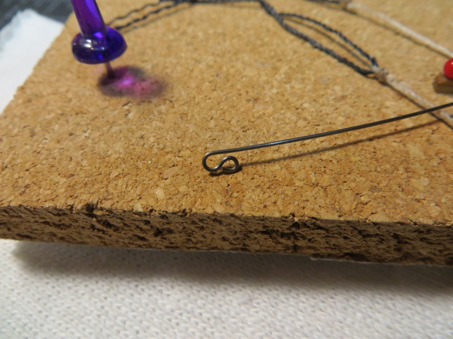
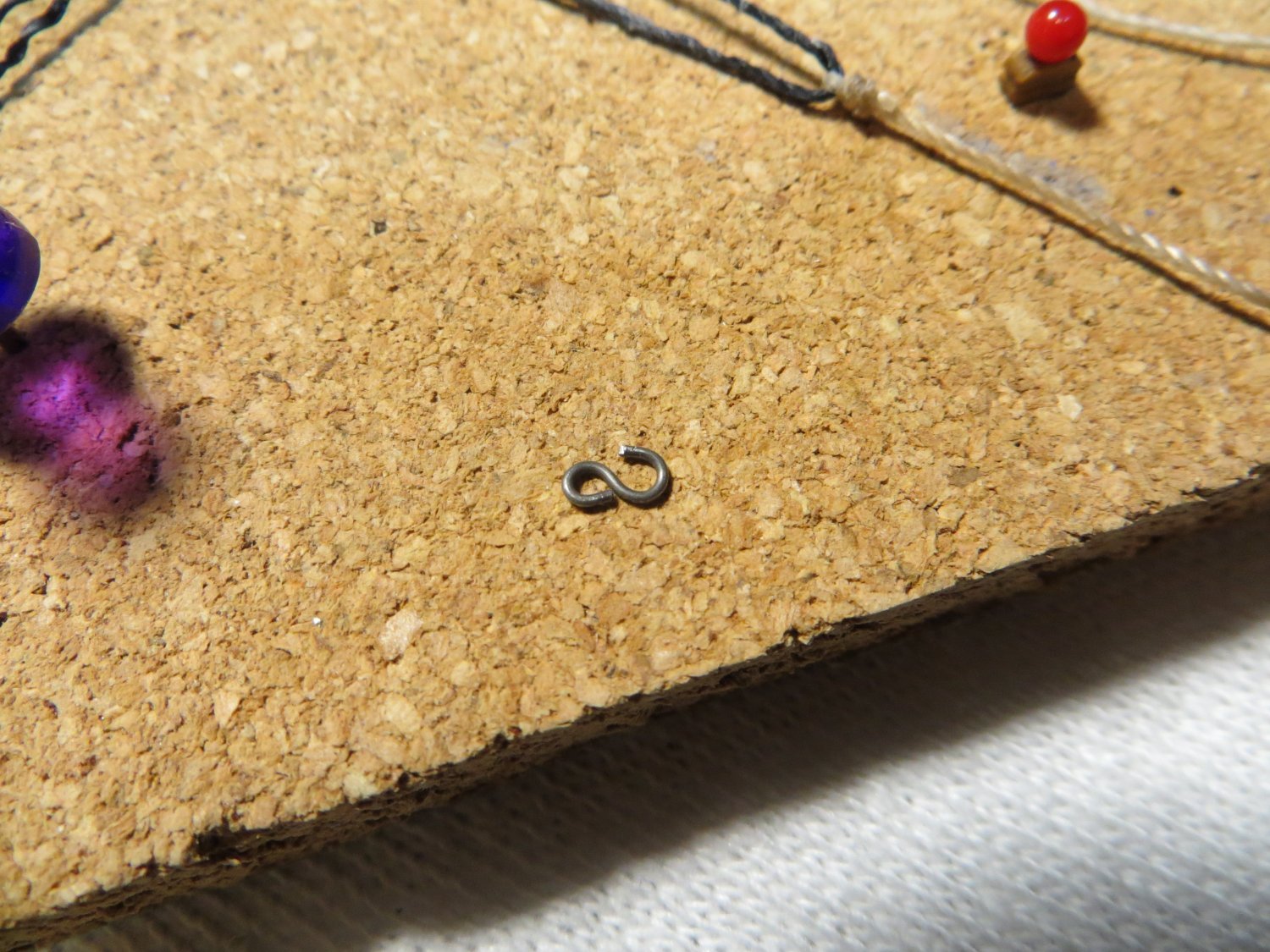
-
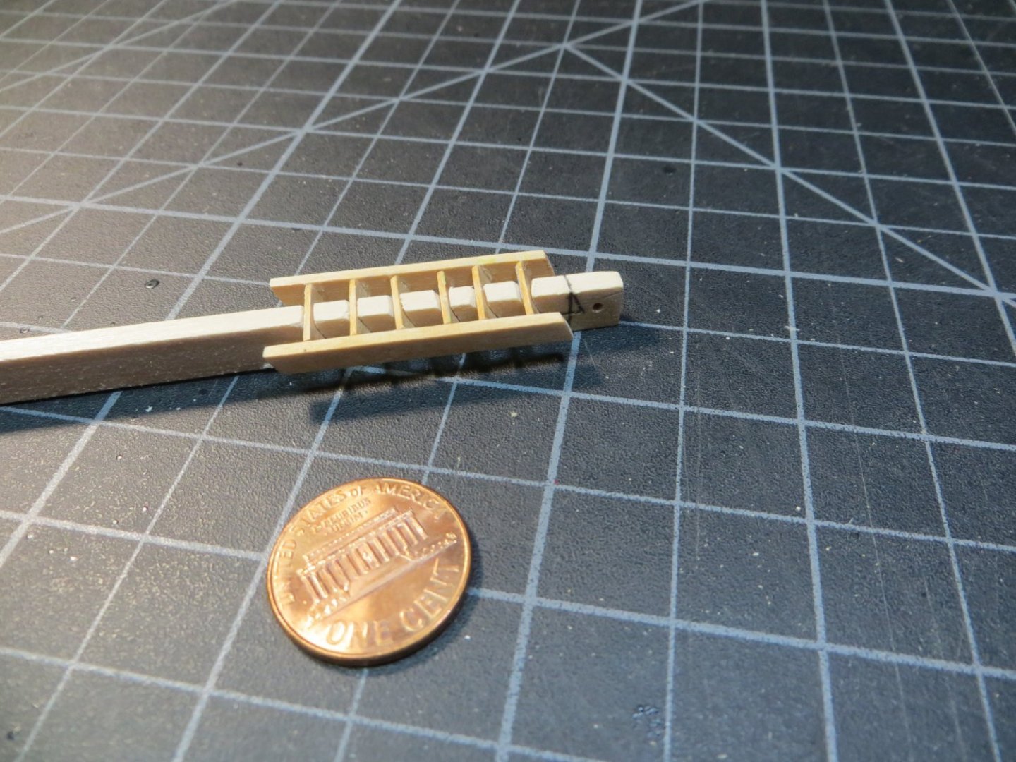
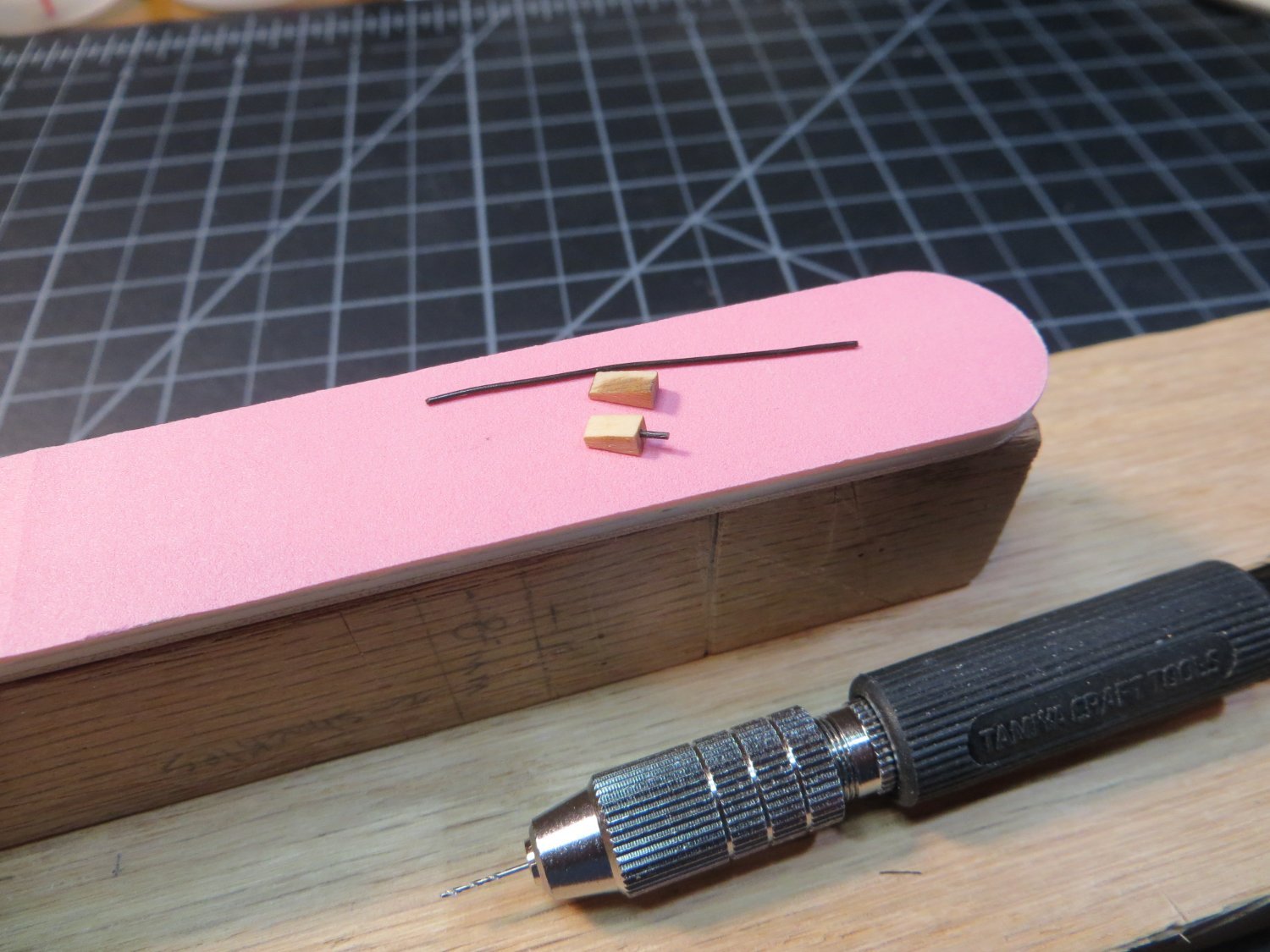
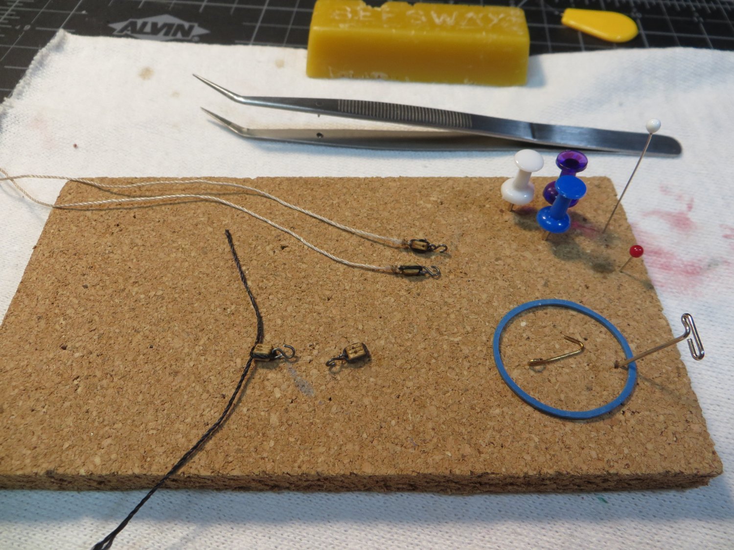
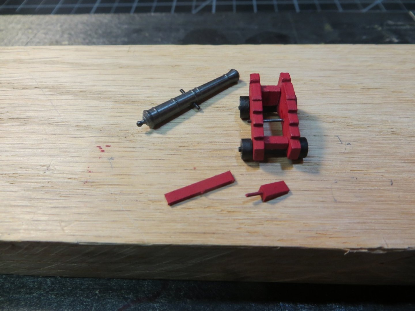
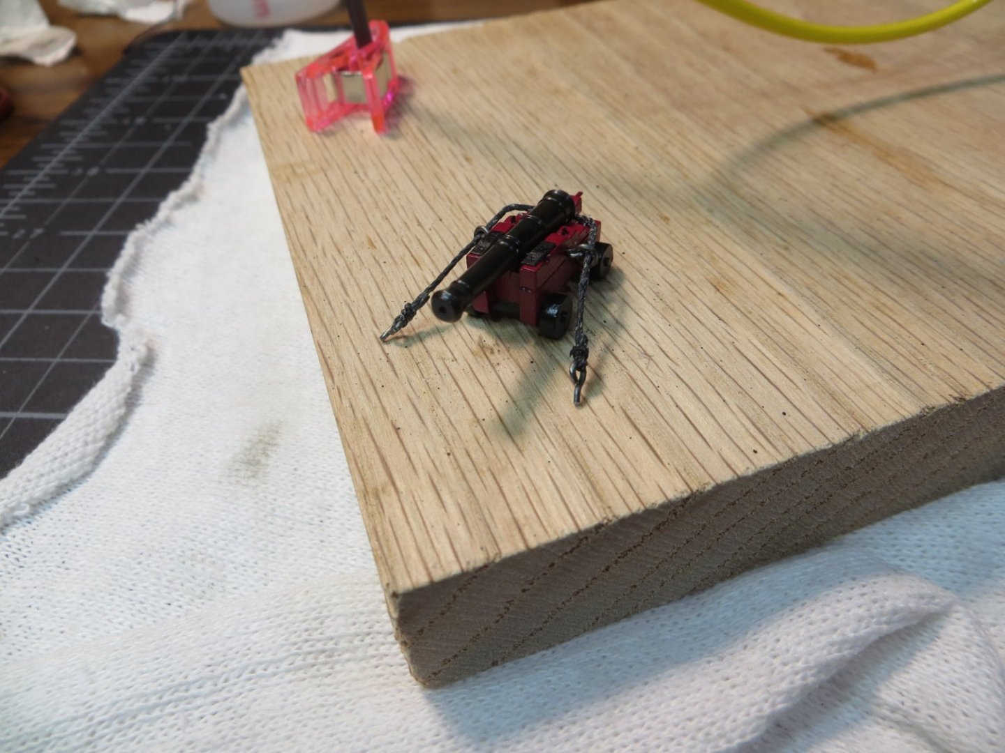
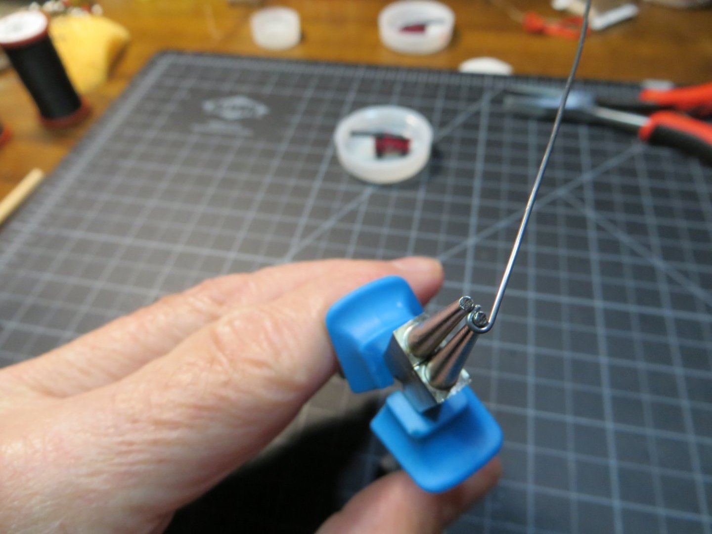
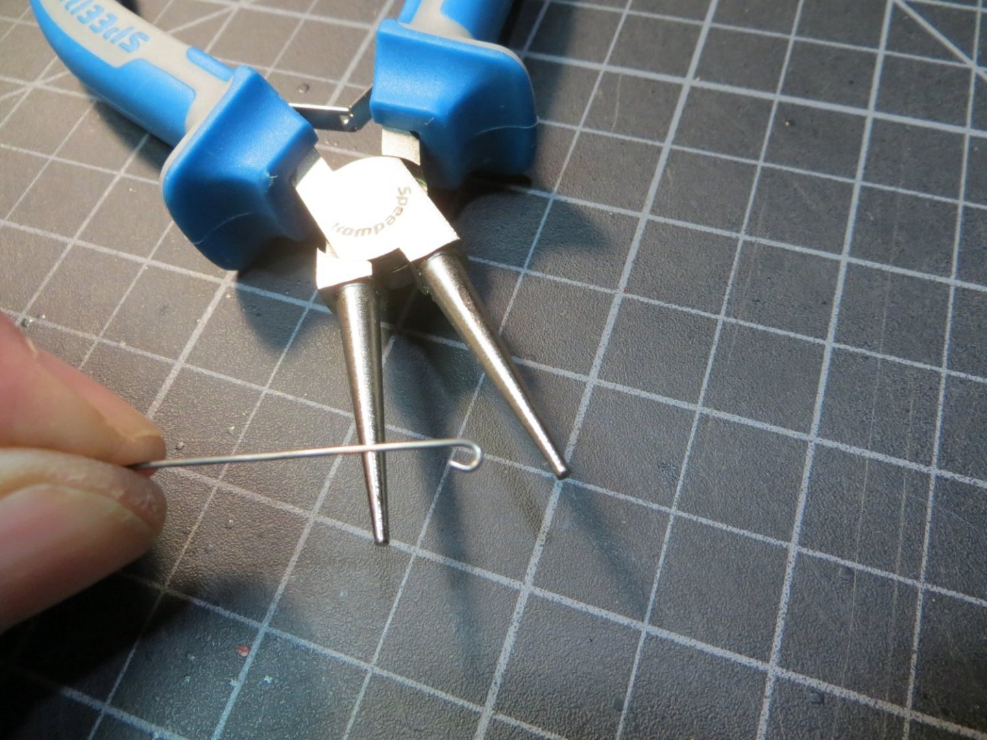
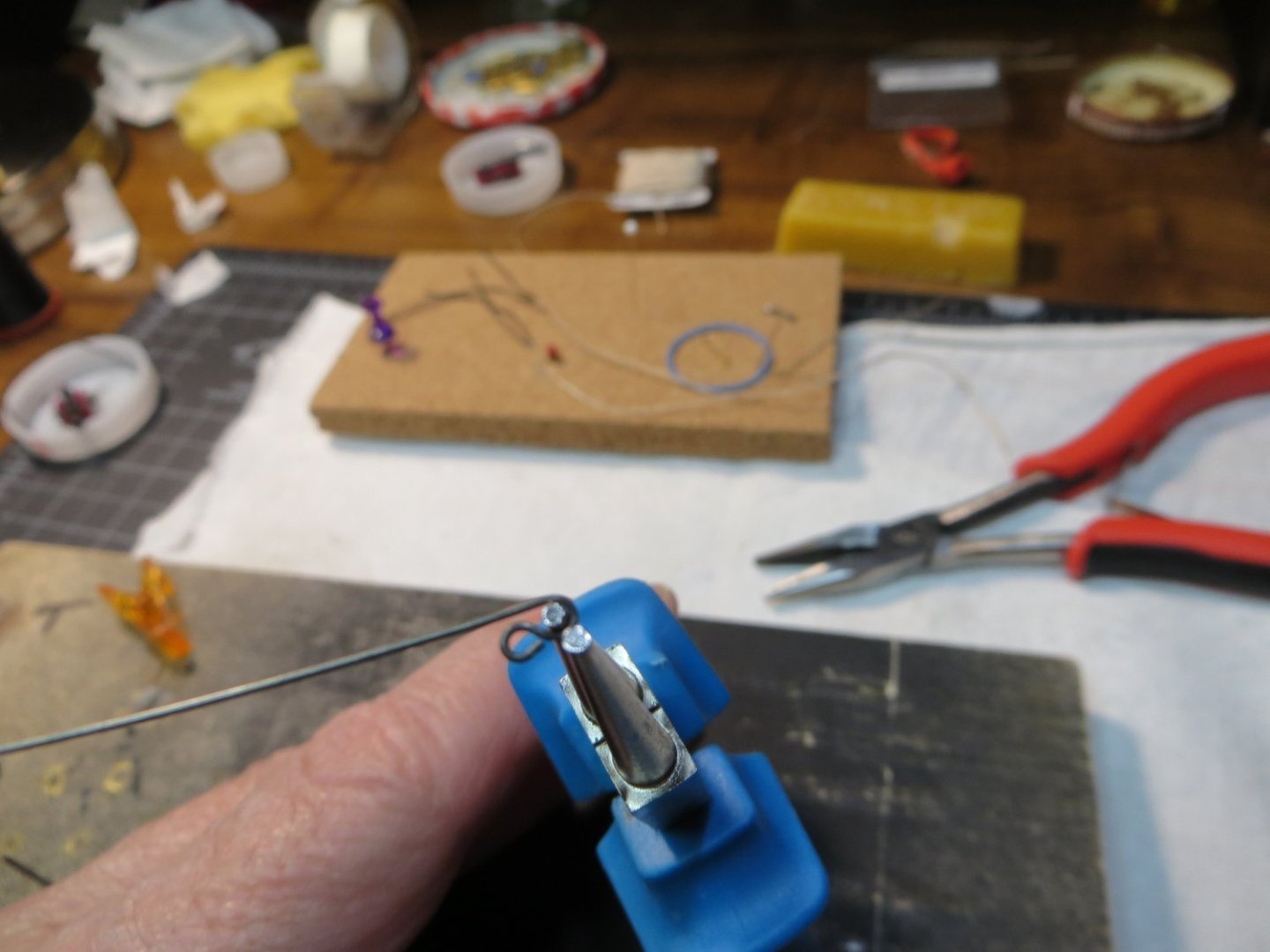
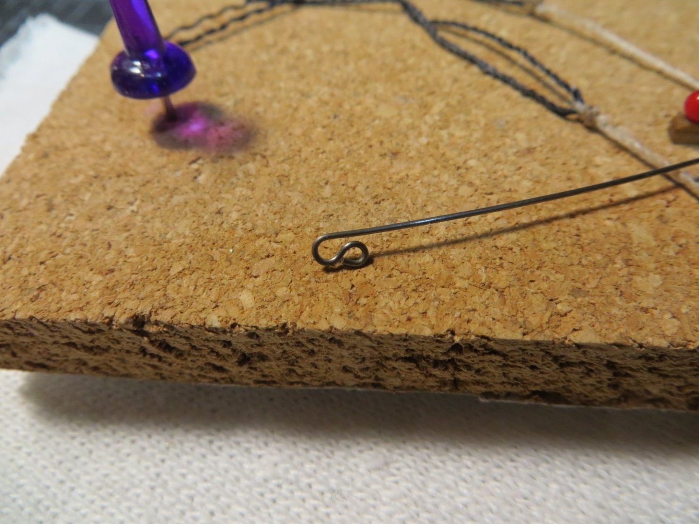
Make and Install 4 Cannons under the Focsl Deck Happy New Year to all my fellow Rattlesnake builders! I have one more deck to plank. But before planking the focsl deck, 4 cannons that are located under this deck need to be built and installed. I made one cannon, (seems like that was a long while ago!) to use for setting the height of the gunports. So, I need to build 3 more from the kits that I purchased from Syren Ship Model Co. There is a lot of work involved in building these little things! This is taking many hours to complete! Chuck Passaro provides very good instructions, so I’m not going to cover that here. In spite of my best effort to set the gunport height accurately, I still ended up with the cannons being a bit too tall. This is an issue other’s have mentioned with the Syren cannons on the Model Shipways Rattlesnake. To compensate for this issue, I did the following: a. Using mini-files I deepened the groove that holds the pins of the cannon barrels b. Deepened the slots that the front and rear axles fit into c. I also used a 1/32” x 3/32” piece of stripwood for the carriage bed board to lower the barrel I decided to try using “Brass Black Metal Finish” to treat the brass cannon barrels. Other’s have mentioned this on their build logs. I really like the way the blackened cannons turned out. I also bought the “Dark Annealed” steel wire for the metal fittings on the carriages. I intend to use this type of wire throughout the build. It seems to be a better fit for this older ship. Brass wire & fittings were used on my Bluenose build. Bluenose 1 was a “newer” ship circa the 1920’s. Here are before and after pictures of the cannon (pre-rigging) There are lots of eyebolts, S-hooks and rings required for rigging each cannon. I’ve developed a pretty good method for making this hardware. I made a post on this topic in my Bluenose log. But I thought I’d update that post here with the Rattlesnake. Method for Making Eyebolts and S-Hooks 1. Use a pair of round-nose pliers to bend the wire about ¾ of the way around the nose 2. My pliers are 1/16” at the tip. I wanted smaller eyebolts so I have a 3/64” drill bit inserted into a build-board. Place the wire loop over the bit. Squeeze with needle-nose pliers to tighten the hole around the bit 3. Use the same pliers to grasp the shaft and bend the wire to square up the end under the loop. Snip off the long end for your eyebolt! 4. If you need an S-hook, put the uncut shaft back into the round-nose and make another loop going the opposite direction 5. Snip off the end, so it’s even with the bottom of the first loop. After I attach the open end to the rig, I gently close the loop tight with pliers. In my next post I will show how I’m rigging the cannons and setting them up on the gun deck. Best regards, Ed


-
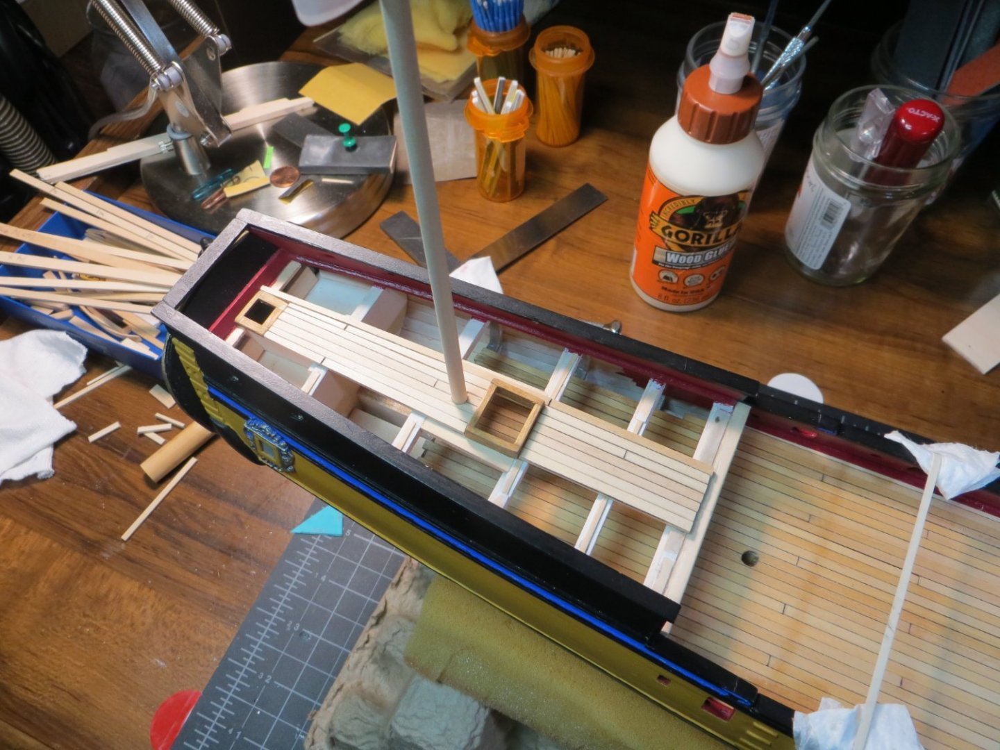
I finished planking the Quarter deck, so thought I would give you all an update. This deck actually took me longer to complete then the main gundeck. There were more details like the coamings and ladderway that added time that I did not have on the gundeck. The planking got pretty hairy when I got close to the gunwales. Since the sides angle inboard there's not a lot of room to work. Especially at the narrow part of the stern. Don't ask me how this happened, but the deck on the port side ended up about 1.5 millimeters wider than the starboard side. I had to insert a short nibbed plank on starboard side behind the beam. It's pretty well hidden under the railing. One more plank filled the space on the port. But, a small tapered sliver was needed right above the beam. You can see these diffeences in the first picture. Maybe I was off on the center line? I really tried hard to get that right! Oh well, Only you guys & I will know!! I decided to stain that beam in front of bulkhead I with the darker Golden Oak. I need to add another coat to darken it up a little more. The rest of the deck was stained with Minwax Natural, same as the gundeck. The next step is to build the 4 cannons that need to go under the Focsl Deck . These need to be put in place before I can install this deck. Here are some pics of the completed quarter deck. Thanks, Ed


-
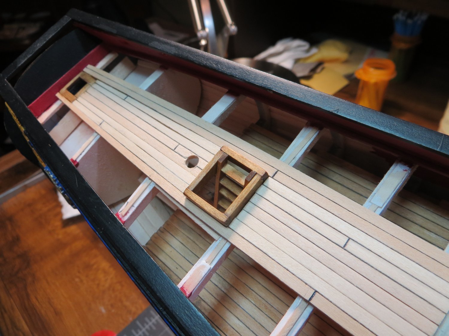
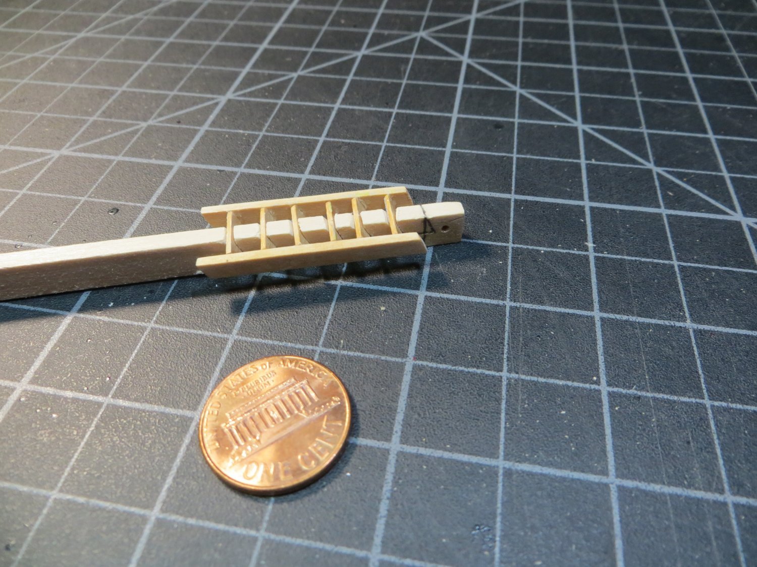
Finally got around to installing the ladder on the quarter deck today. It came right off of the little jig very nicely. Allowing the glue to set for several days seems to have helped. It feels pretty sturdy. After some light sanding, I applied 2 coats of Minwax Golden Oak stain to match the coamings. The ladder was then glued to the coaming. Here is the end result. I think it looks pretty cool! Hope you do too. Ed

-
Ed Ku20 reacted to a post in a topic:
Rattlesnake by Ed Ku20 - Model Shipways - 1:64
-
Ed Ku20 reacted to a post in a topic:
Rattlesnake by Ed Ku20 - Model Shipways - 1:64
-
Ed Ku20 reacted to a post in a topic:
Rattlesnake by Ed Ku20 - Model Shipways - 1:64
-
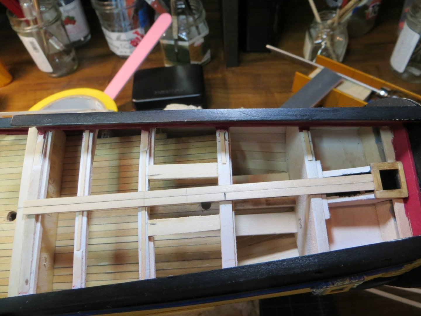
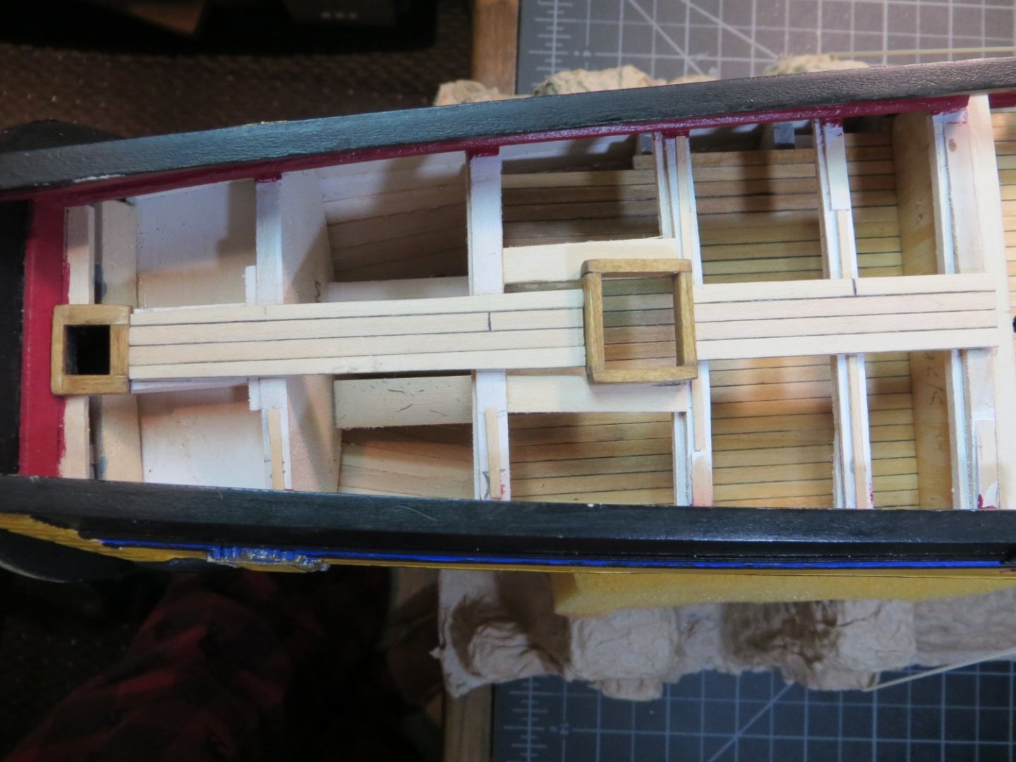
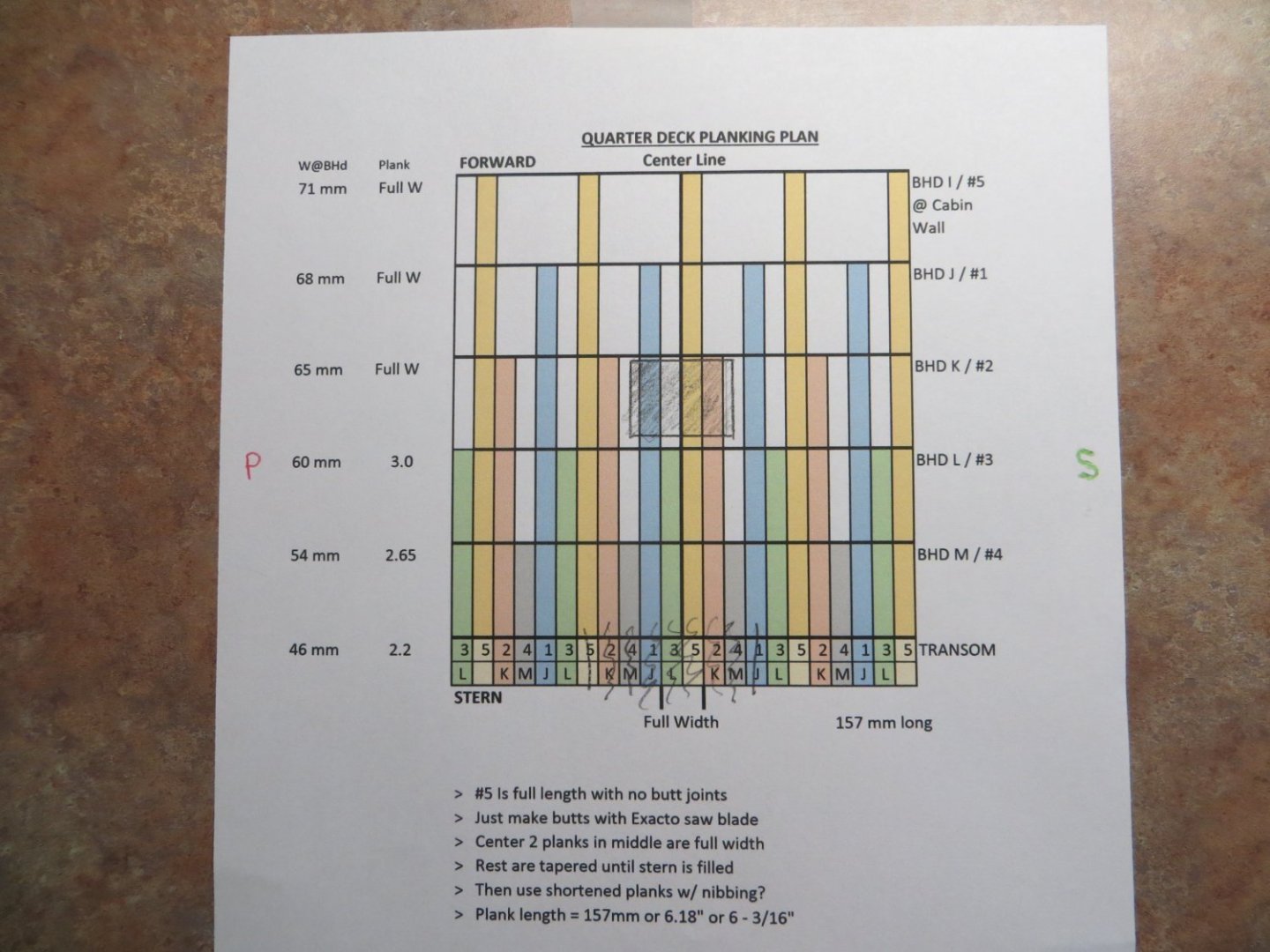
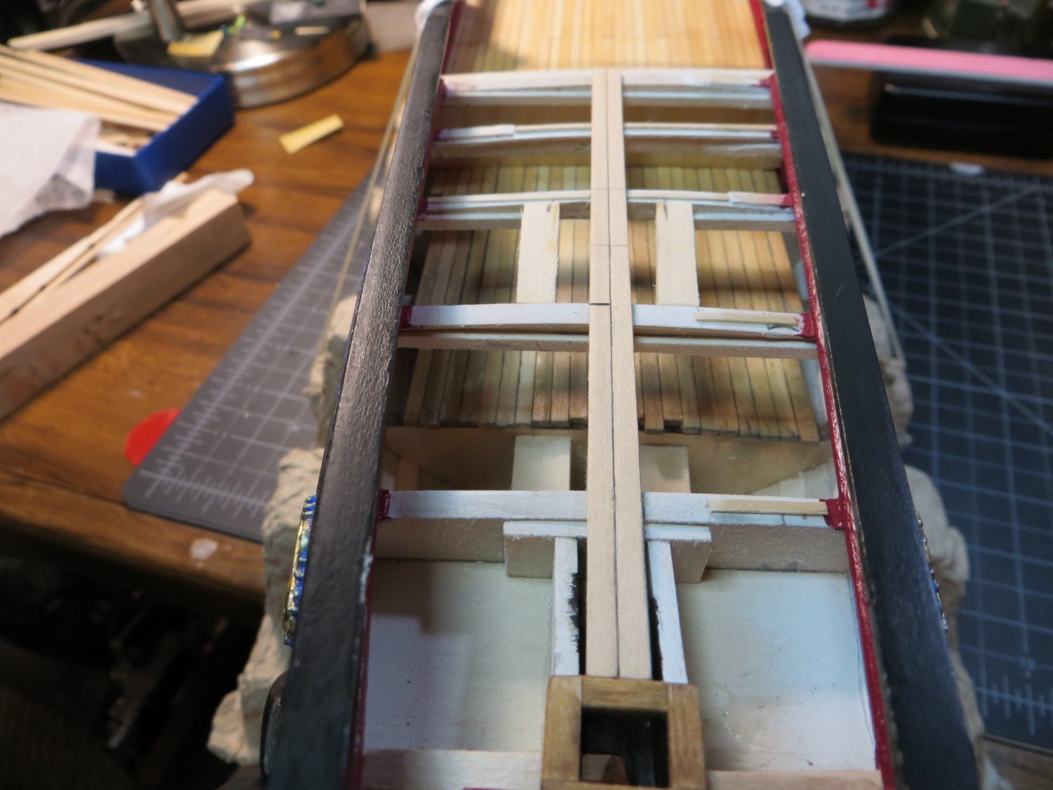
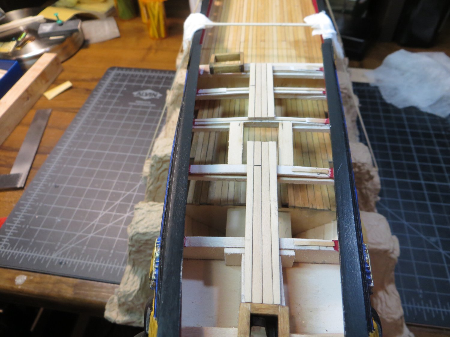
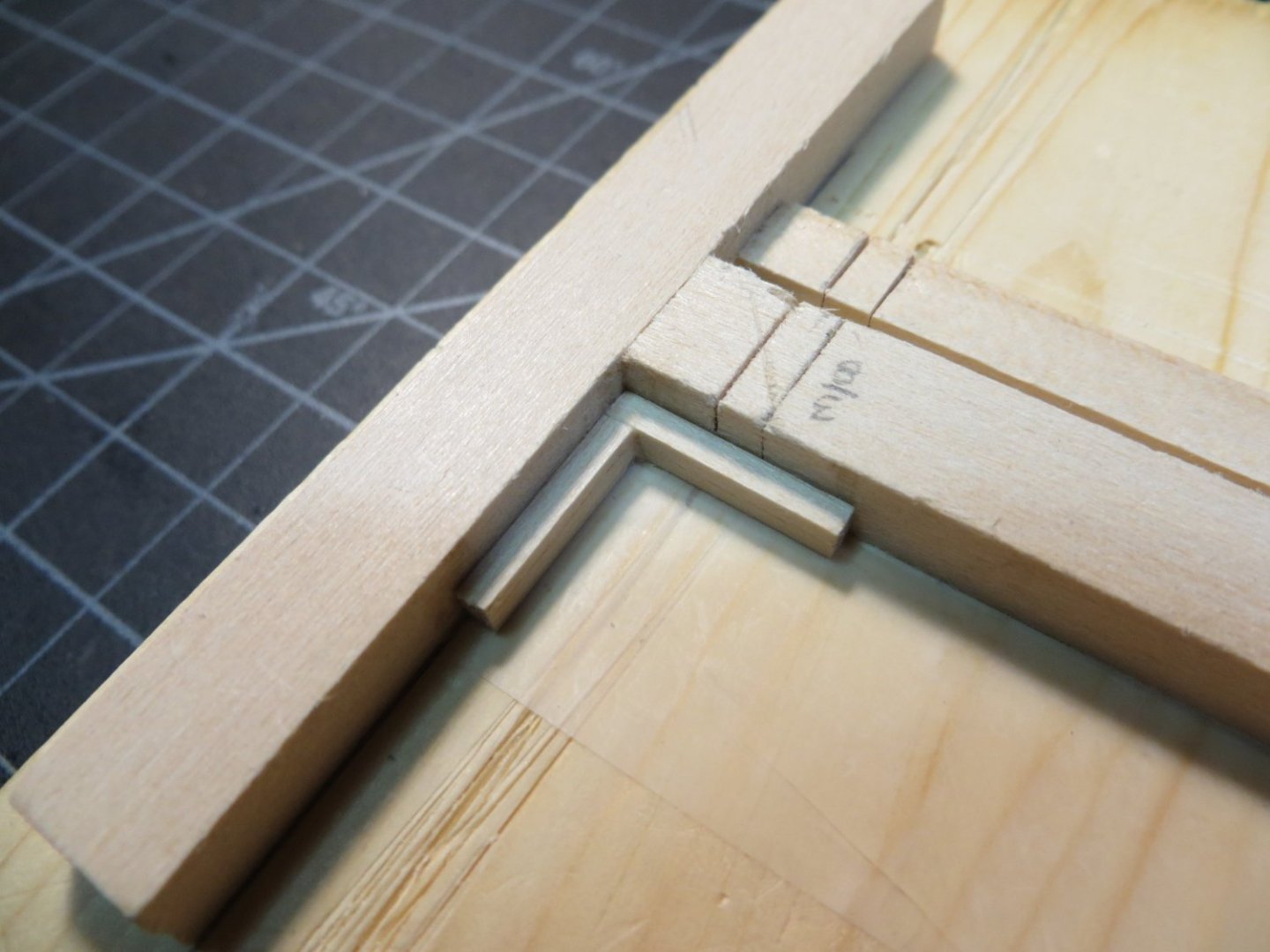
Step 37: Plank Quarter Deck I still have some work to do before I’m done planking the quarter deck, but I thought I would provide an update to cover some progress on a few steps that accompany the actual planking. Also, I took a couple of weeks off from the shipyard. My wife and I took a nice vacation in the Caribbean to celebrate our 45th anniversary. Now, it’s back to deck planking. · The first thing I had to do was make a new butt stagger plan for the Q-deck. These planks need to taper at the stern, but are full width at bulkhead I. A lot of the butt joints are hidden. I faked them with an Exacto saw cut and a graphite pencil. Here is a pic of my planking plan. · There is very little help from the plans and/or build logs on how to handle the inboard stern bulwark. There doesn’t appear to be anything to support the deck planks on the inboard side of the transom. I decided to add a ledge to support the deck planks where they butt up to the front of the transom. I also added supports for the coaming where the rudder post makes a hole in the deck. · While I was at it, I also added supports between BHDs K & L for the ladderway coaming. Be careful not to block the location of the mizzen mast. It’s pretty close to the ladderway. · Made the coaming for the ladderway as follows: o Per plan coaming is 20 x 18 mm. Use 3/32 x 3/16” stripwood, PN3628 o Stained the coamings with Golden Oak to set them apart from the deck o Glue the rudder post coaming in place at the transom, after staining. Need this before planking · Next, I set the 2 center deck planks to be sure they are centered and square. I decided to glue these as full-size planks, so there is a square base to build the tapered planks from. Once the glue dried, cut out the space for the coaming. After cutting out the space for the ladderway coaming · I did not glue the ladder coaming in place yet. Continued to build the deck around it o I used my mini-plane to do the tapering of the planks (one of the best purchases I have made!) · After I covered the width of the ladder coaming, I decided I better make the hole for the mizzen mast. The wisest thing I did was to start with a smaller hole then required and use the smallest dowel to check the angle of the mast the 2 holes provided. This gave me room to make adjustments. I made a template using the NMM plans that Gregory provided to get the angle between the quarter deck and the mast. I’m very satisfied with the results. Thanks Gregory! · Also, before continuing with planking, I decided to build and install the ladder for the quarter deck. I tried to do it without the jig that is recommended in the plans. I thought if I could make a rabbet cut on the inside of the stiles, I could build a sturdy ladder. This didn’t go well. So, I made my own version of the jig. I’m still worried about it falling apart when I try to remove it from the jig! I’m going to let the glue dry until after Thanksgiving. I’ll provide more pictures after I install the ladder. I hope everyone has a great Thanksgiving Day with family! Best regards, Ed