

victory78
-
Posts
30 -
Joined
-
Last visited
Content Type
Profiles
Forums
Gallery
Events
Posts posted by victory78
-
-
Hello Nils, congratulations from me too on the completion of your Zeesboot model. A very nice work with many details. Maybe you can do a tour with a boat on the coast... have fun.
- Keith Black, Mirabell61, FriedClams and 1 other
-
 4
4
-
Hello Nils, nice that you like the schooner, I take my time with it. A lot of time. -
Hi Nils, I'm also taking a break from model making. Other important tasks are currently pending. The models stand there and remind me again and again. At some point it will continue.
-
Hello Nils, exciting project, I wish you a lot of fun and I like to watch. What's next for the Zeesboot? -
-
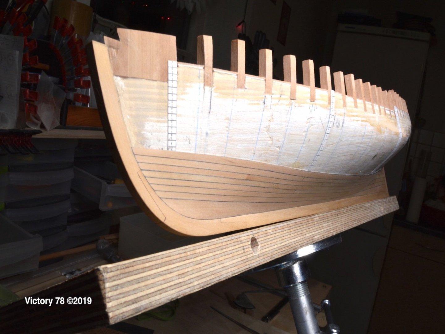
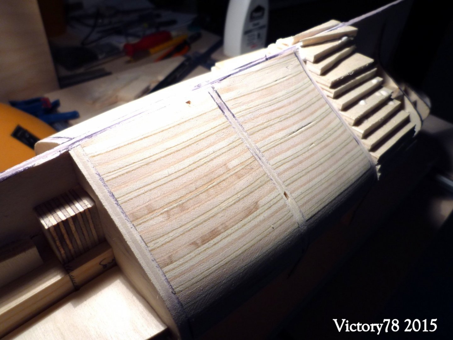
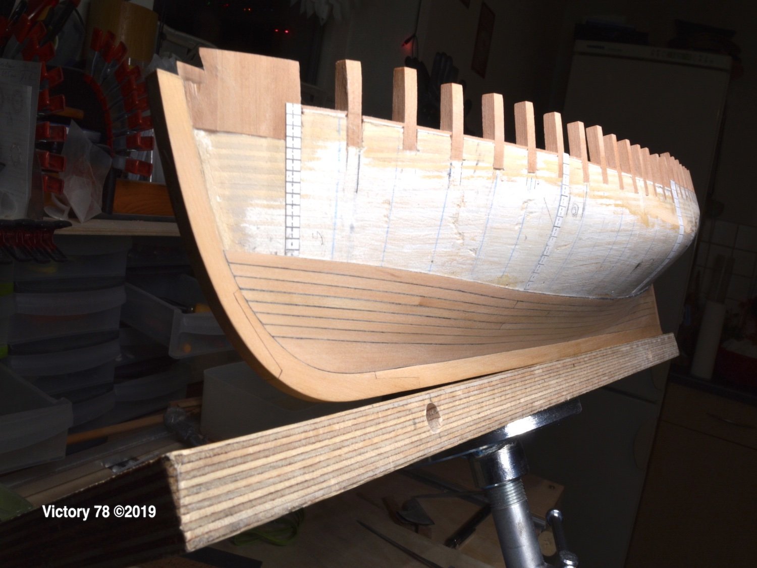
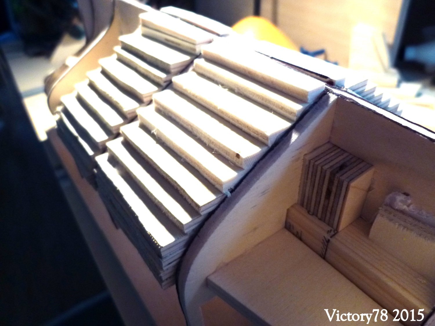
Hallo everyone, lets planking the hull …I'll start with the keel plank. It is easier to build them at the beginning than to put them between the keel and the plank at the end. I also have more leeway for bulwark.
I build the keel plank in two parts. The part would originally be 23 yards long. Was it in one piece? I don't know, but it would have needed a big tree.


Plank by plank was glued. Some stealers were necessary.Alternating side by side of the hull.
The pictures show it.

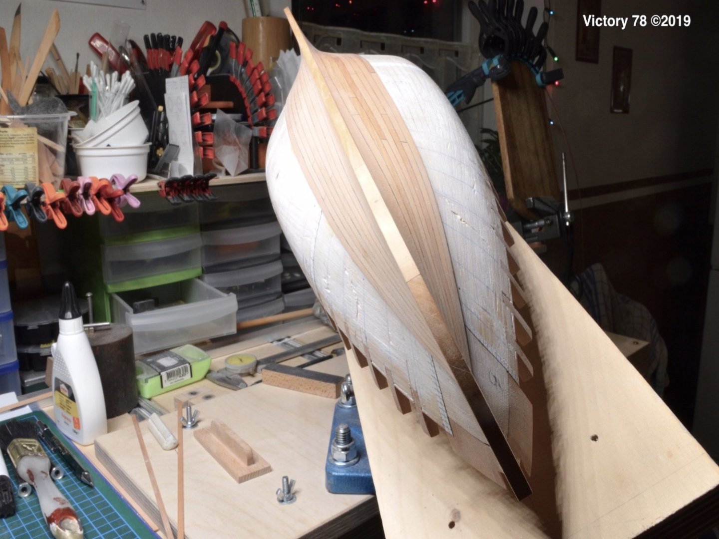
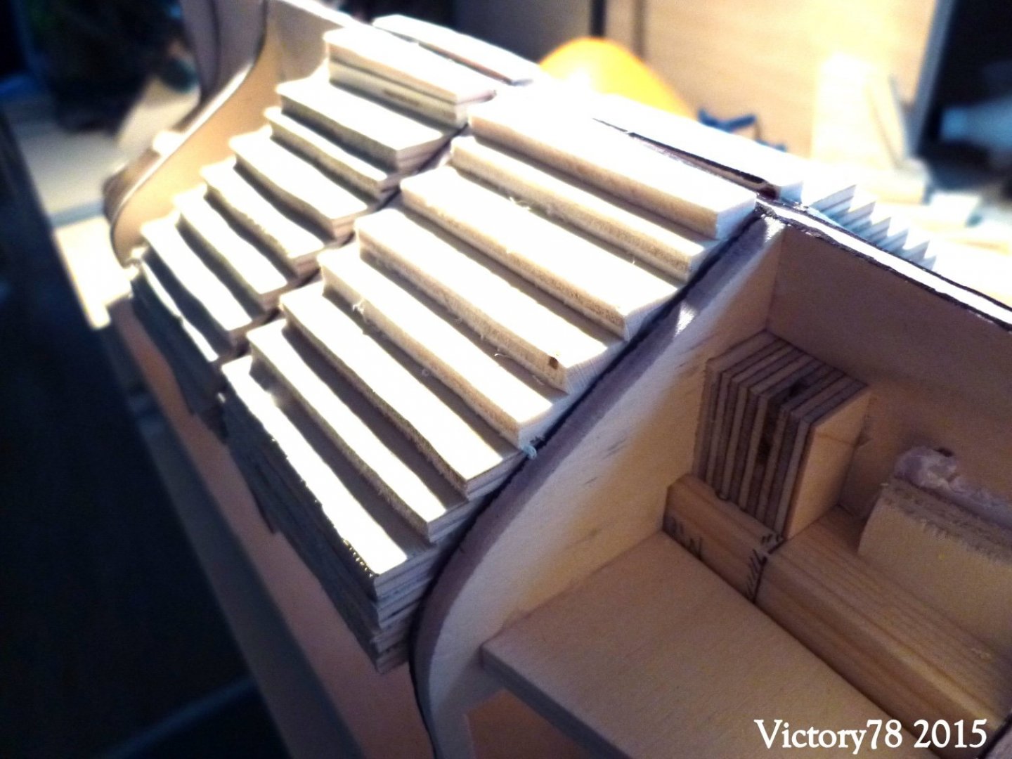
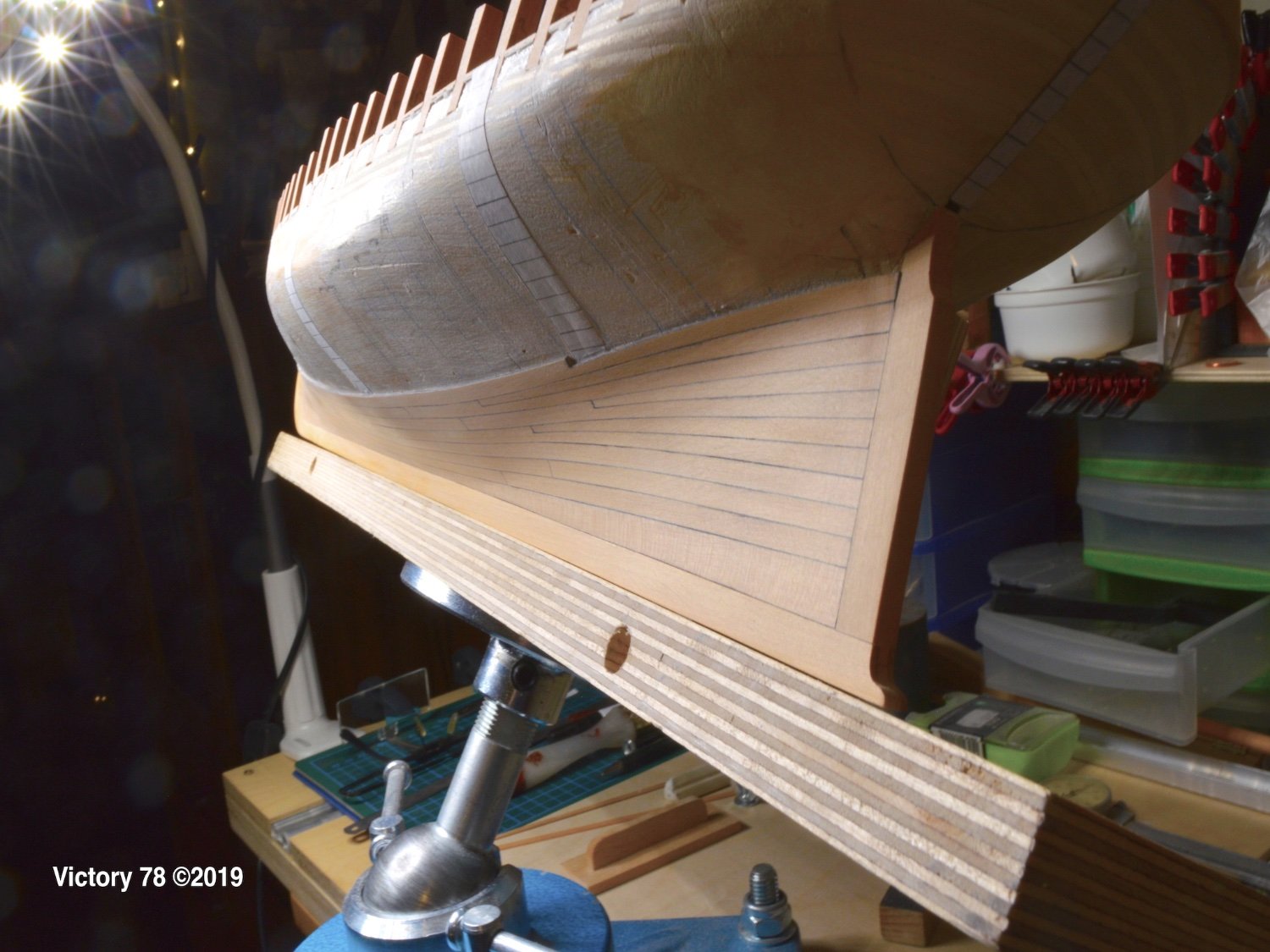
… a short break to planking the stern.
- GrandpaPhil, BETAQDAVE, jlefever and 8 others
-
11
-
it goes on …
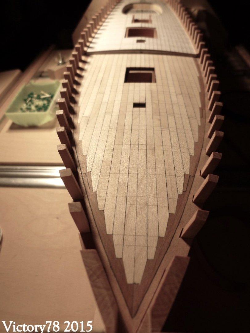
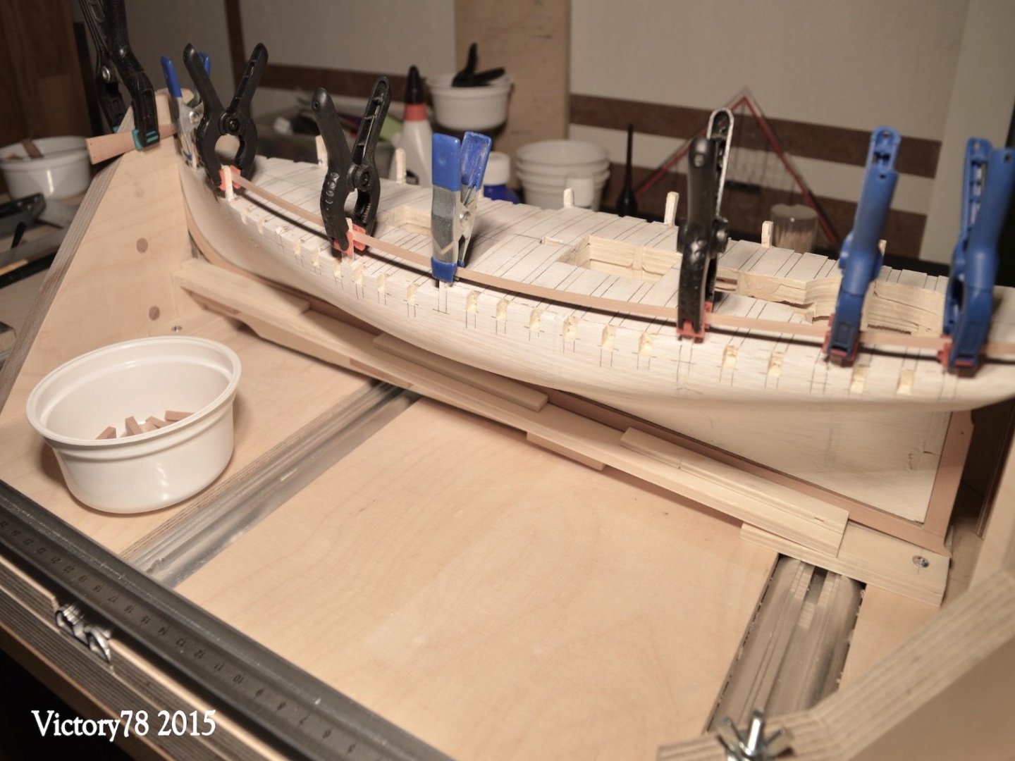
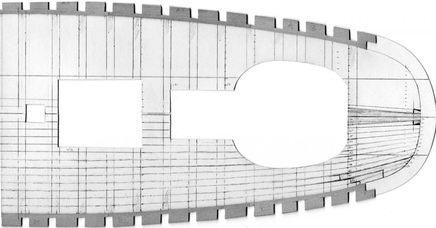
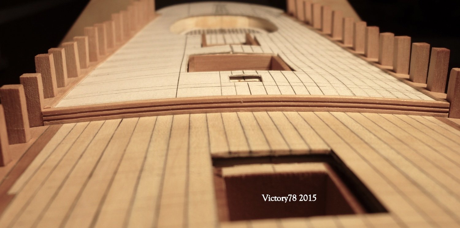
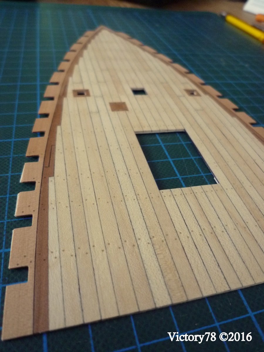
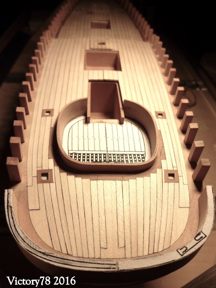
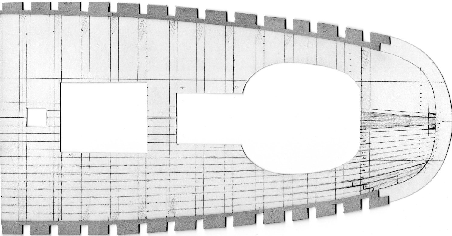
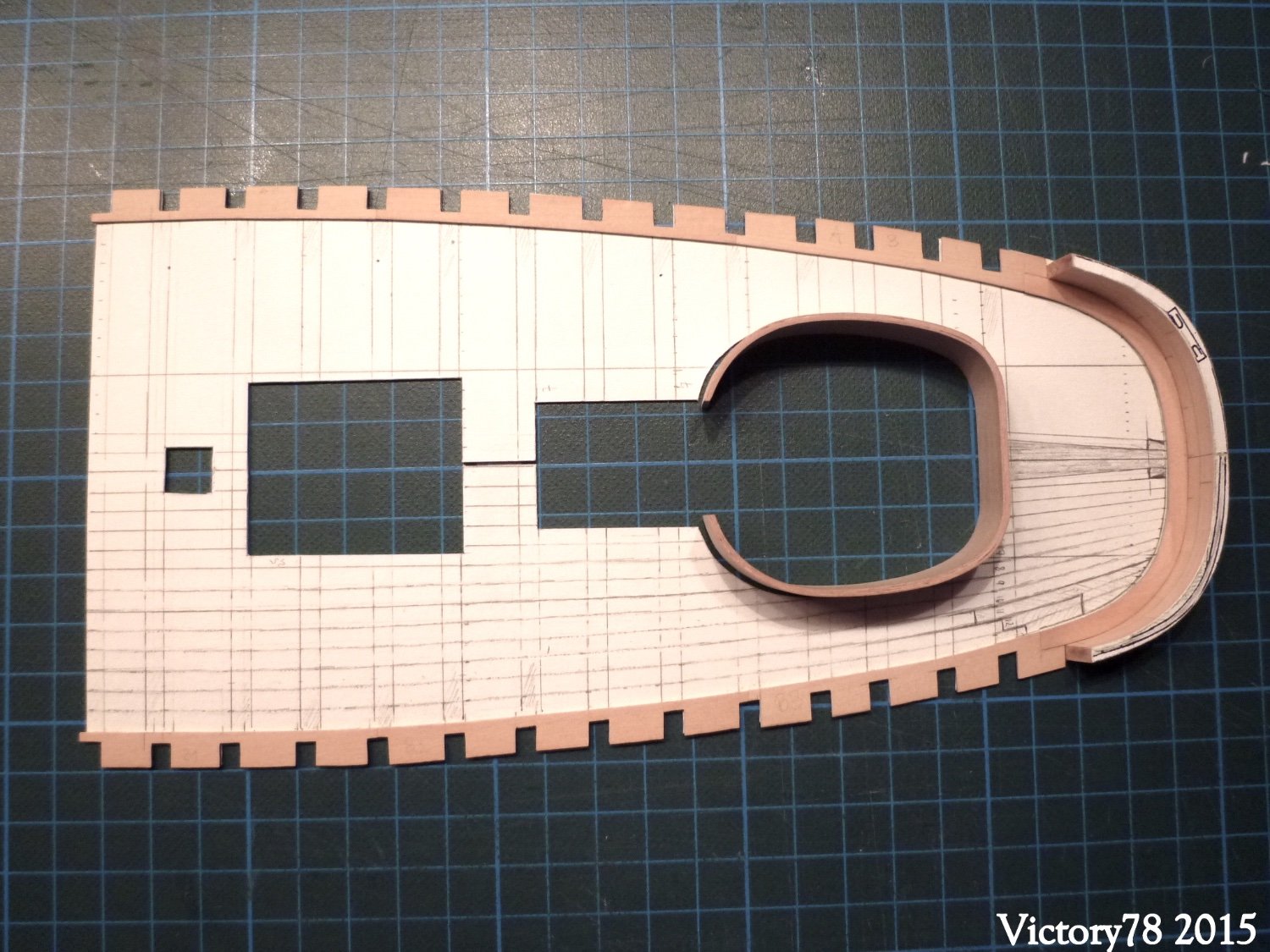
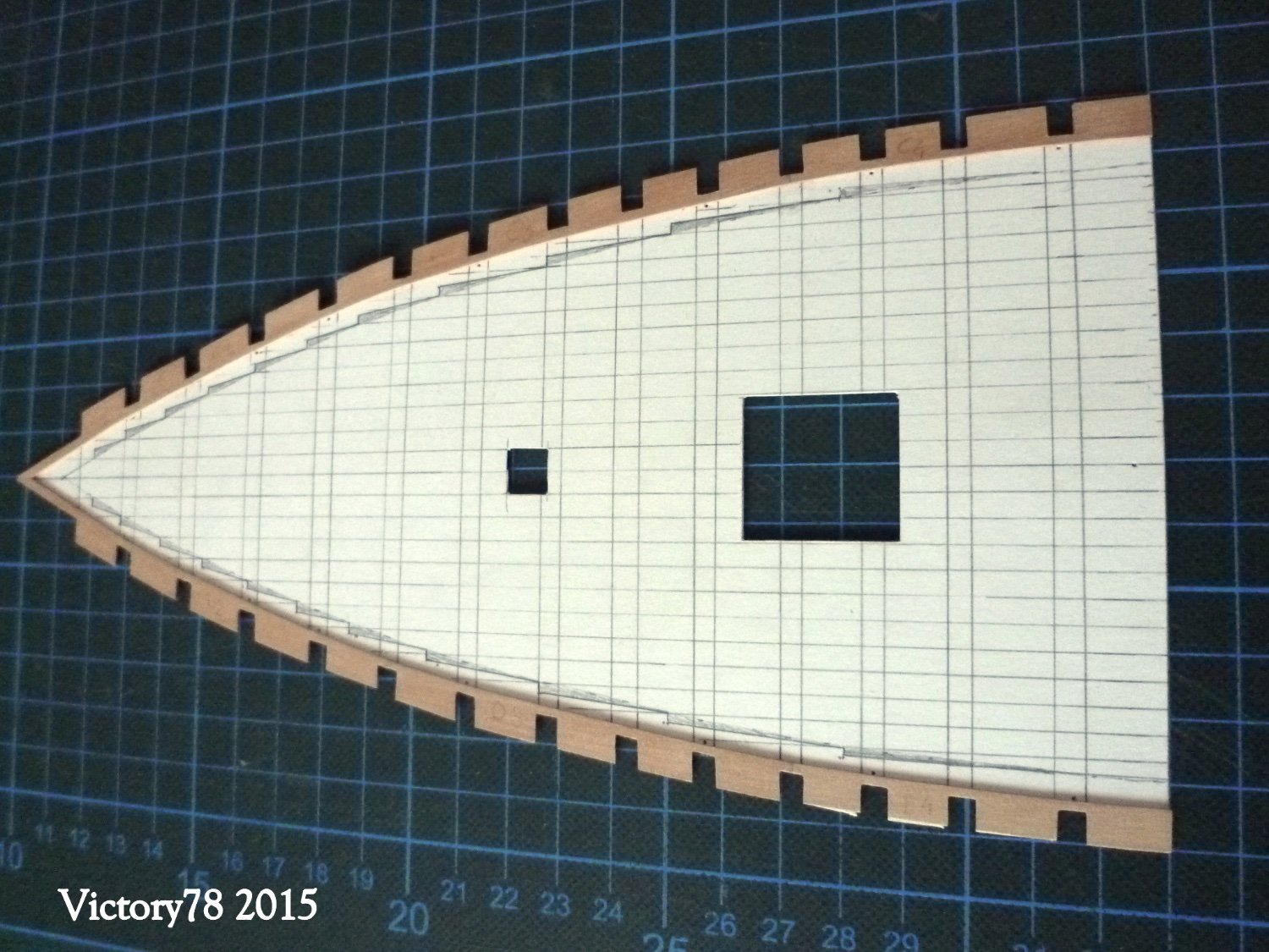
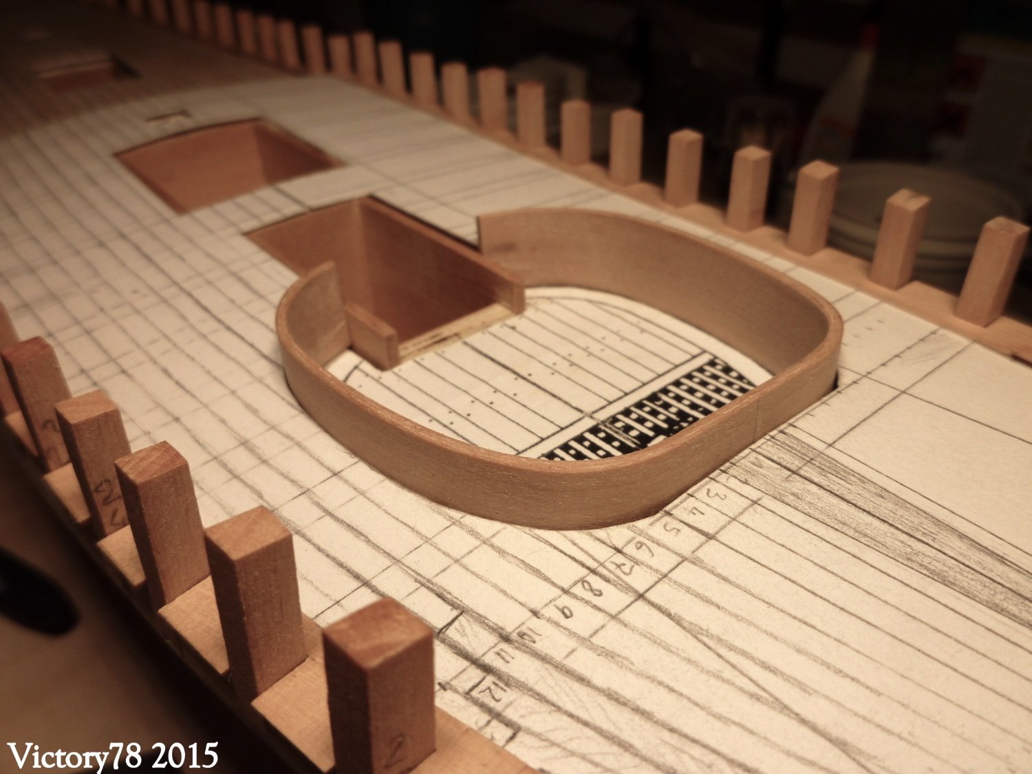
I have not planked the forecastle and forecastle deck directly on the ship. The cardboard template with the waterway was the basis and could be placed on the hull to check.
The advantage is that an error can be corrected more easily and there is also more space to work.
by the way; at this point and to this day i am not sure if and where i will paint the model. Hence the different wood colors.
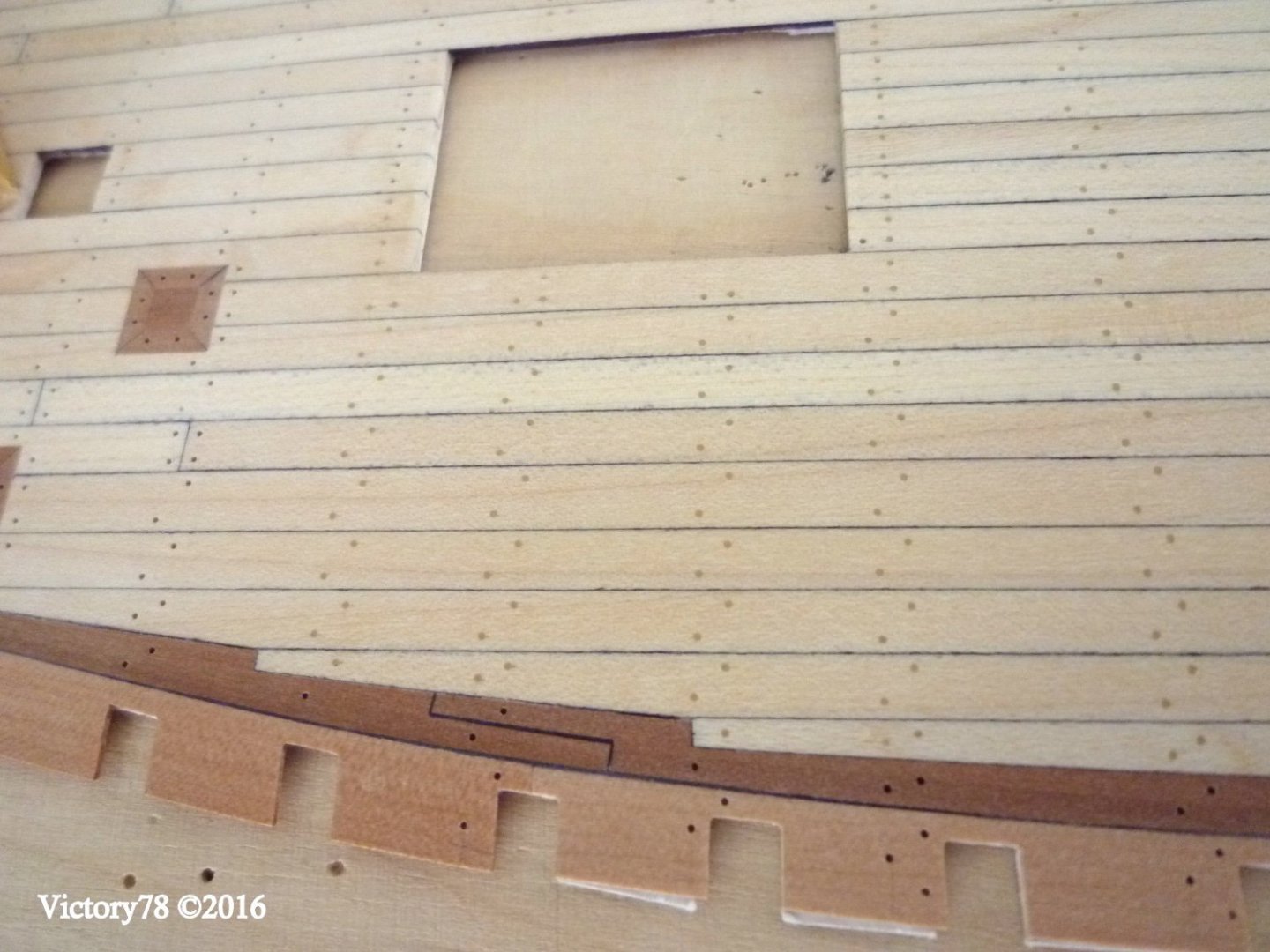
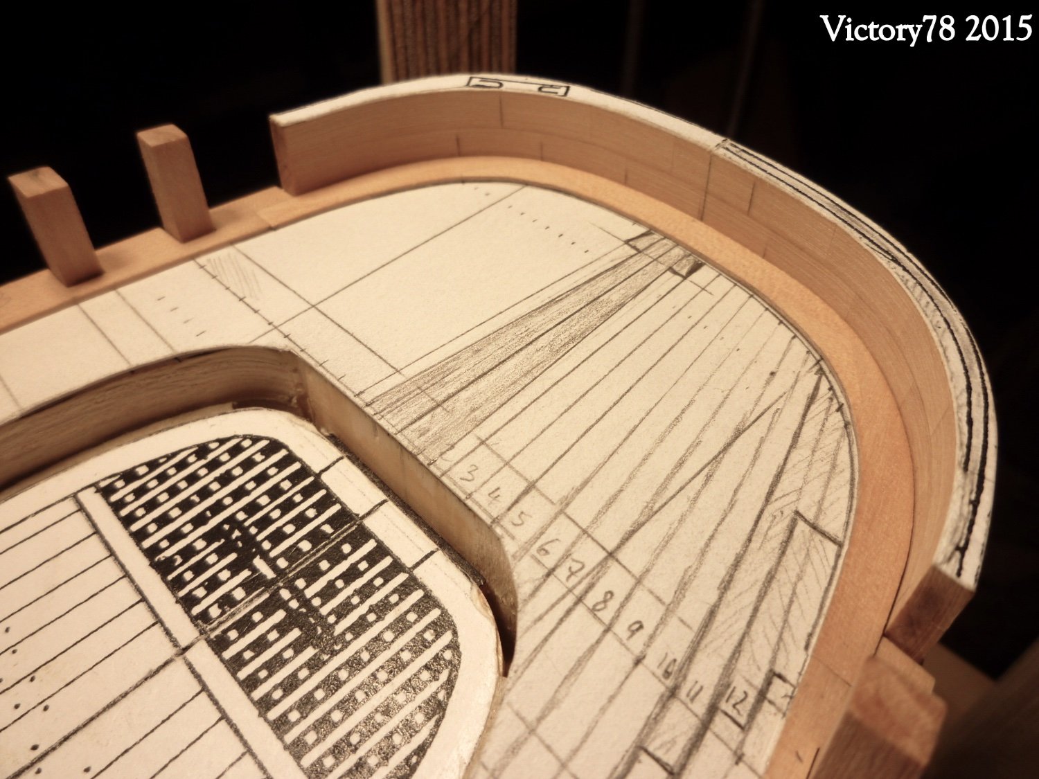
I made the planks out of maple wood. The beams were built from dark pear wood. This gives a nice contrast. The plank picture was drawn. The body wood was worked out from the drawn plank scheme, assembled from several parts and glued to the template. The floorboards were then laid, starting from the outside. On the center line of the deck, small differences could be compensated for without any problems. The caulking of the planks was indicated very subtly with an almost dry Edding.
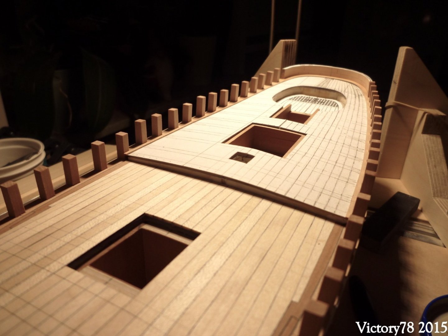
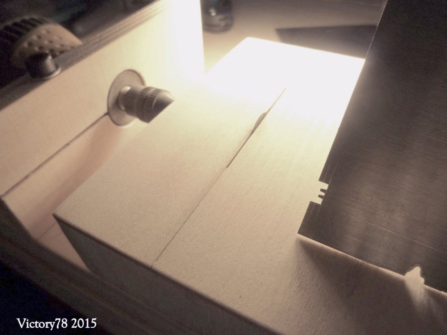
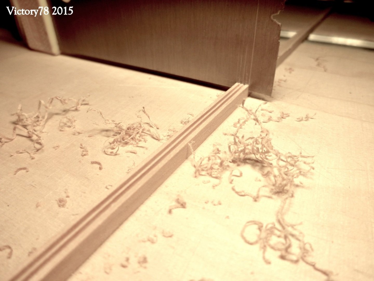
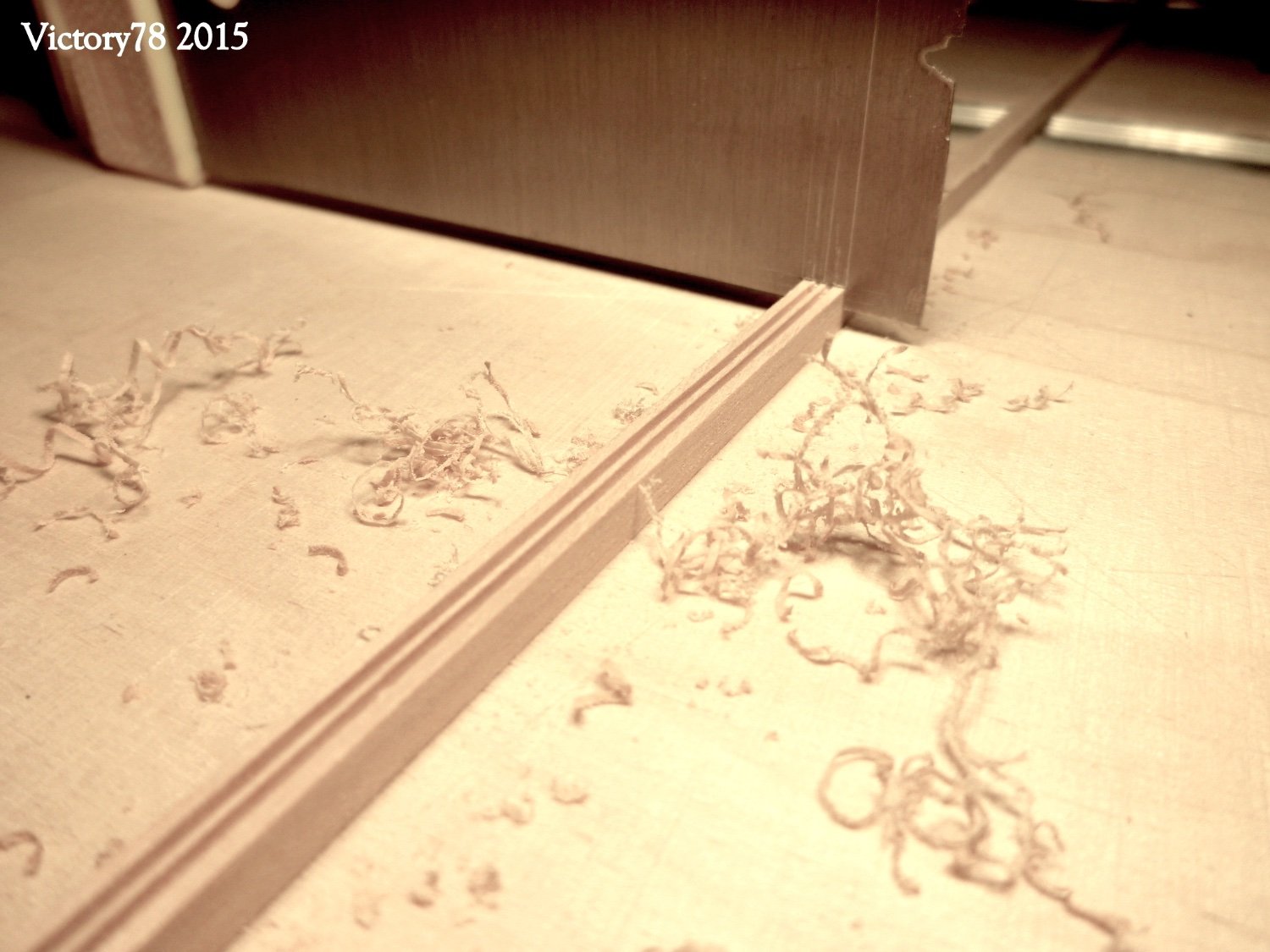
There is a visible deck beam at the transition from the foredeck to the aft deck. This is slightly decorated with a profile. The profile was incorporated with a specially made scraper.
The wood for the bollard, fan and chimney was used.
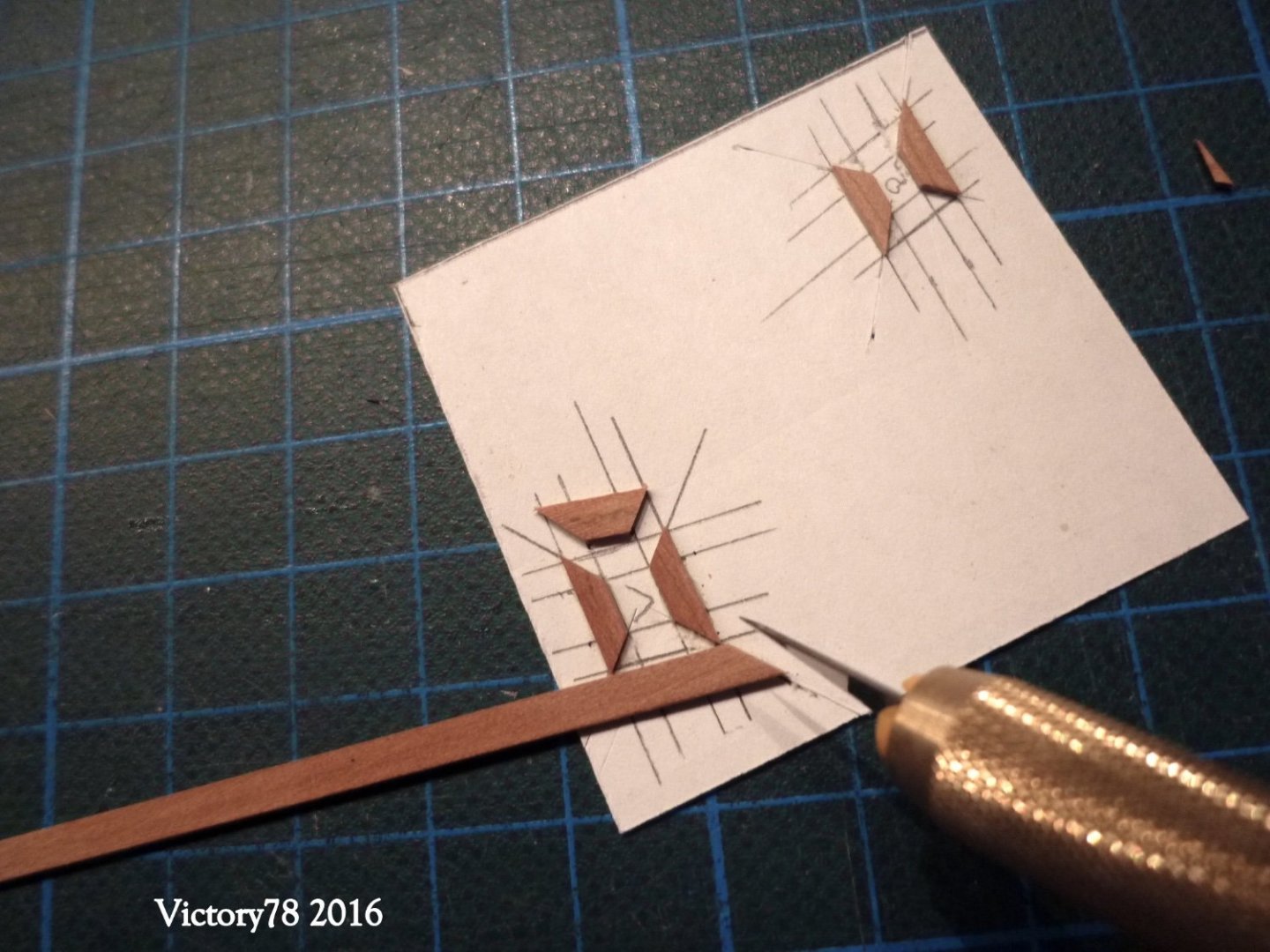

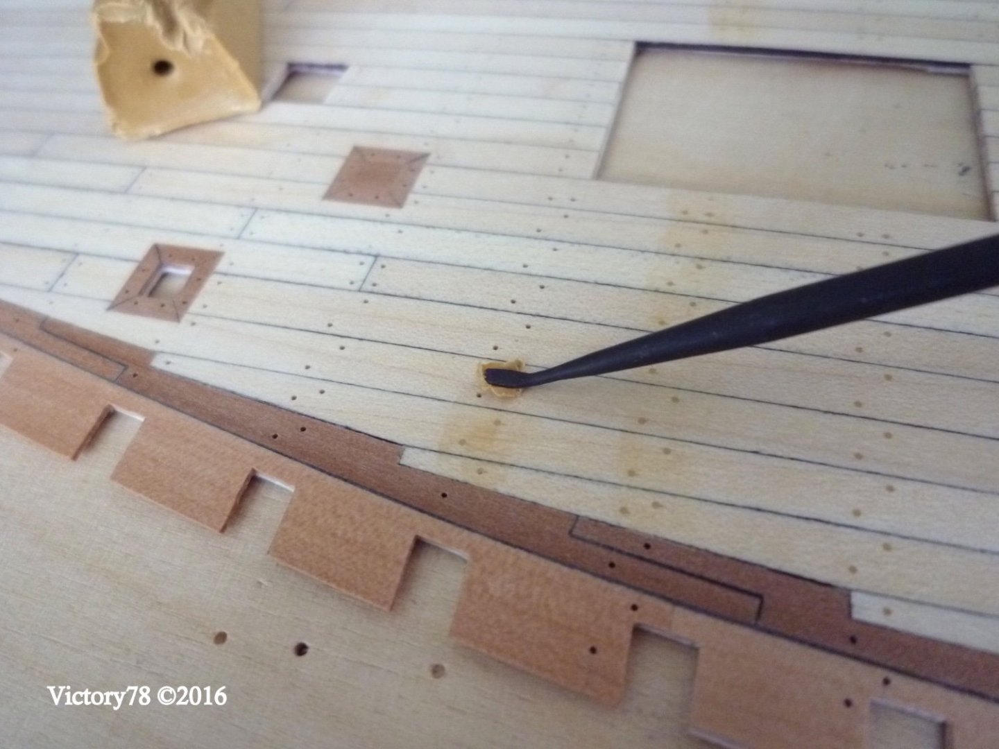
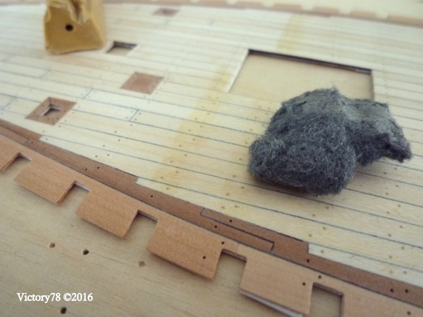
I used wax to represent the dowels. The cold wax was pressed into the drilled holes (0.0197"). Excess wax was removed and polished with fine steel wool.
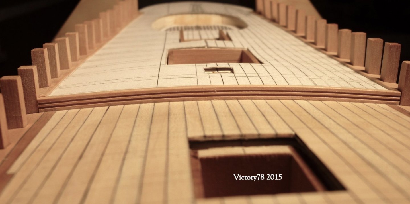
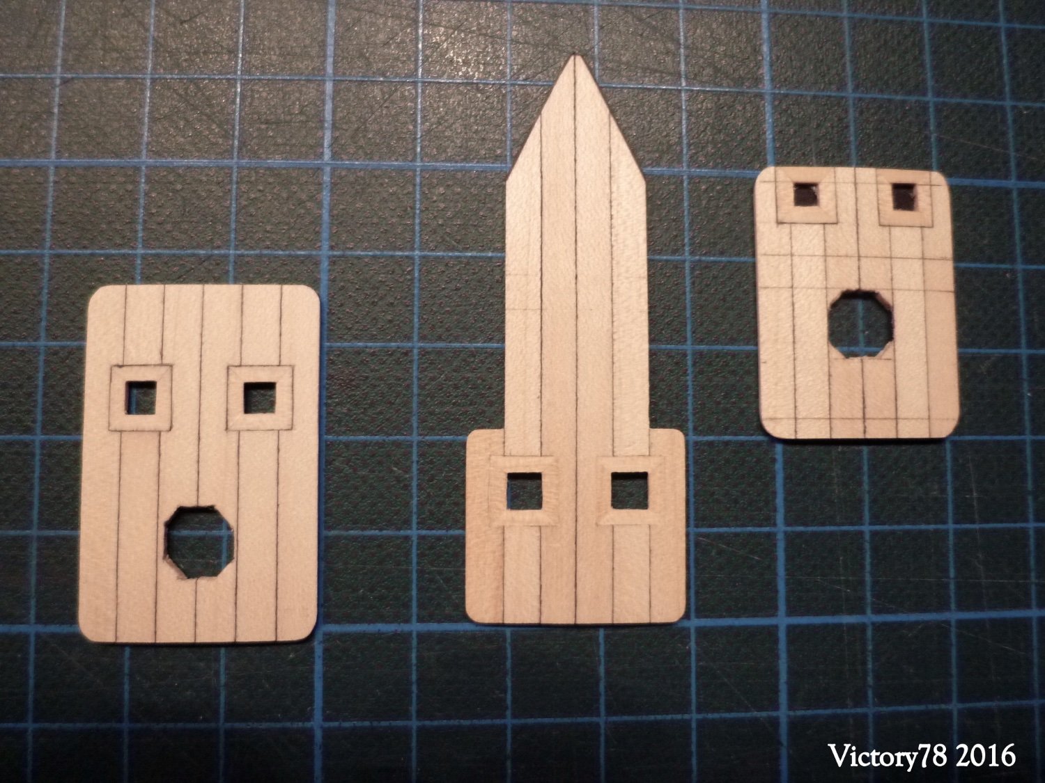
The deck is reinforced in the area of the mast holes and capstan. These doublings were also provided with the body wood for the beting supports.

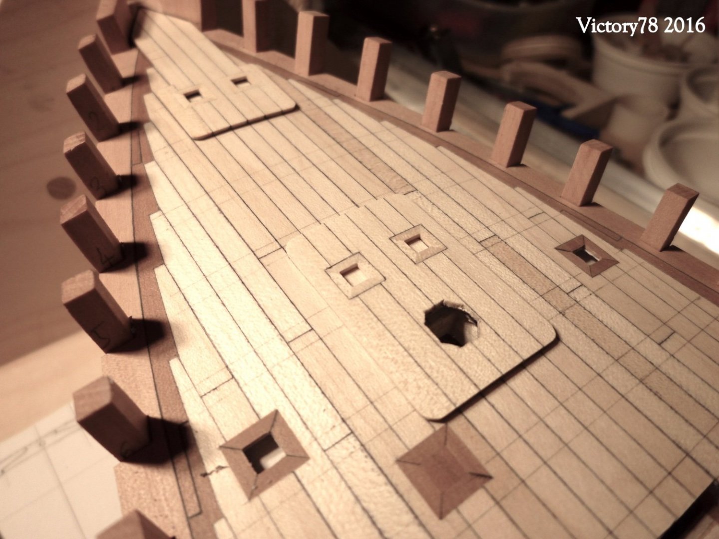
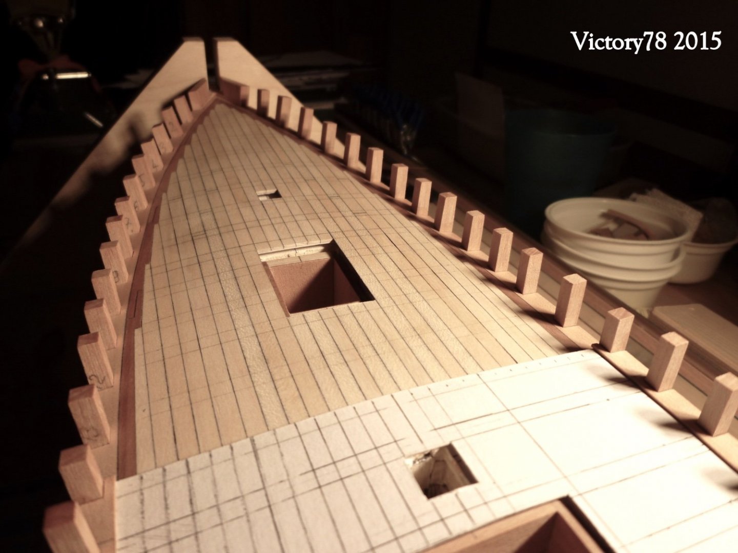
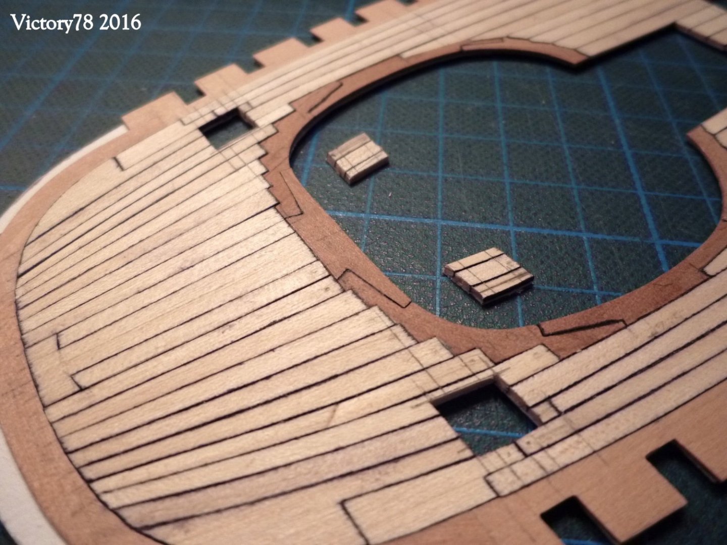
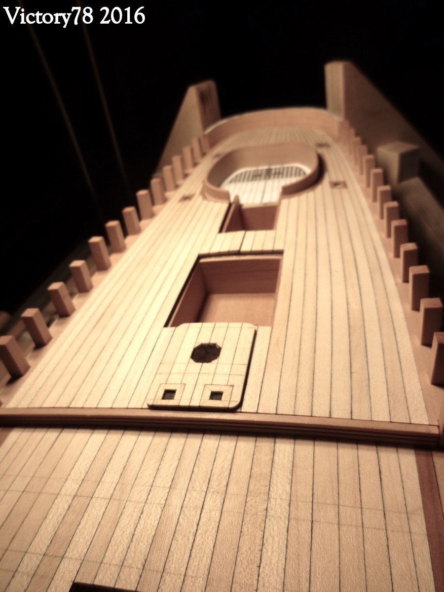
The forecastle deck was also covered with planks. The course of the planks is curved here. Body wood for bollards and the cockpit were inserted and the dowel holes sealed with wax.


That looks like a ship... doesn't it?
I really hope that the translation is understandable.
- bolin, GrandpaPhil, GioMun and 4 others
-
7
-
thank you for the likes…
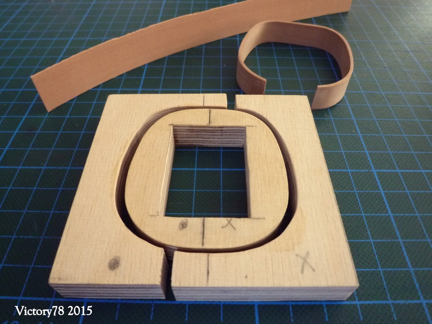
Greg, nice to read that you like the schooner. The community project is very good and a lot of fun. But at the moment I can't do much with my two models, unfortunately it's not the first priority. But I can report on the construction. The good thing about the Scratch model is that you have to think in order to realize something. The cockpit frame is good practice. I tried to bend a 3mm wood that tight but without success. It's ok with the veneer. More challenges will follow.
Keith, yes, I am trying to build a nice model. But I think that the originals were not always so exact - but the scale is correct again.
-
very nice metalwork, Keith
- FriedClams, mtaylor, KeithAug and 1 other
-
4
-
Hallo, thank you for the likes …
The Deck
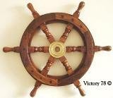
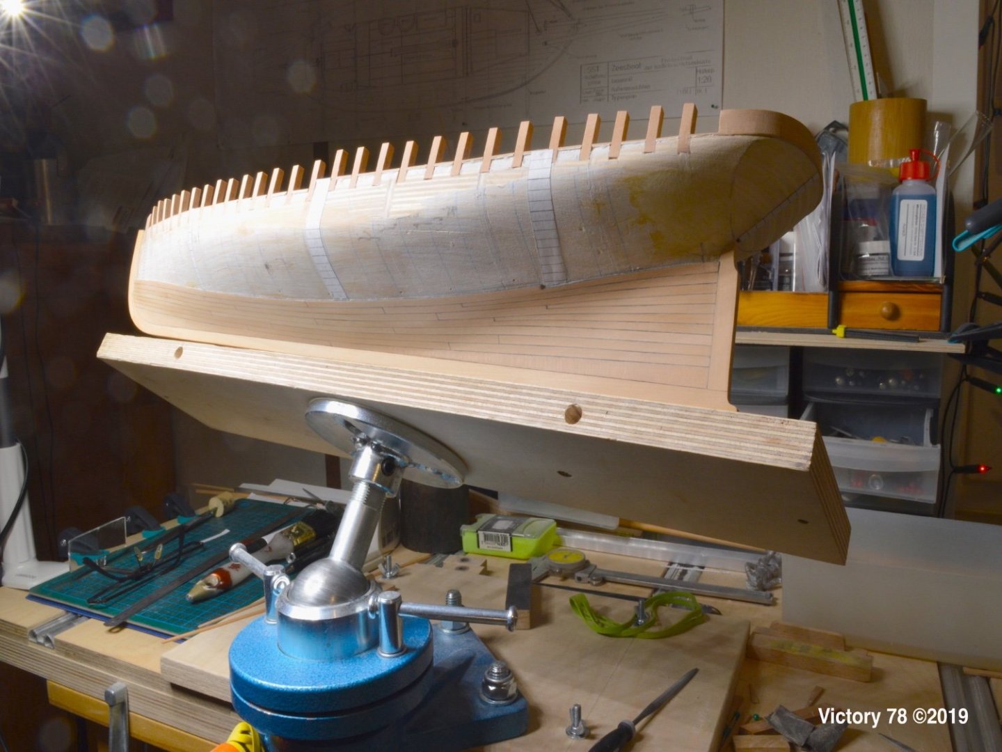
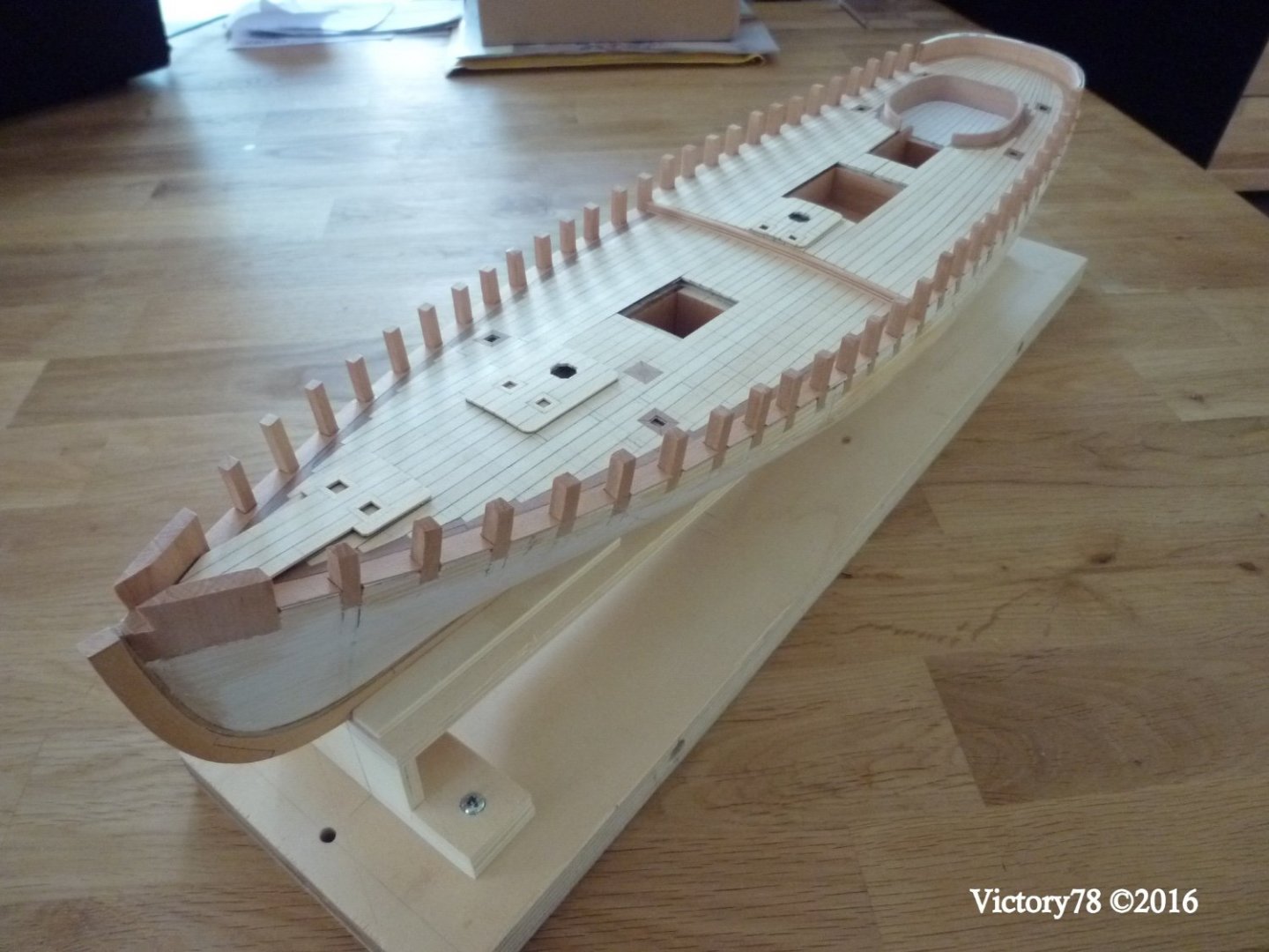
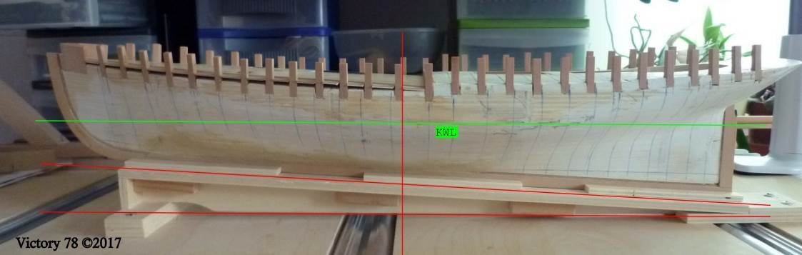
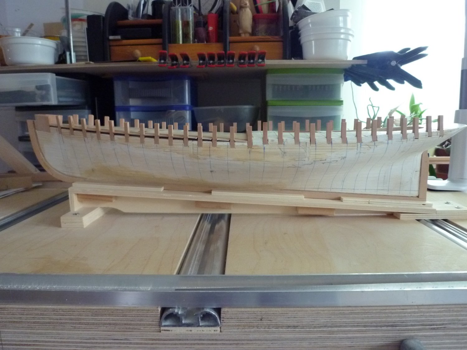
The waterway forms the boundary of the deck. The Timbertop/Bulwarkstanchion break through the waterway at defined distances from the real frames. So the first step is to make the bulwark stanchion (4x4 mm dark pear wood) and insert it in the hull. Indentations were cut into the torso with a scalpel. The bulwark stanchions were aligned with the top of the building frame and glued in place. Step by step until everything was complete.
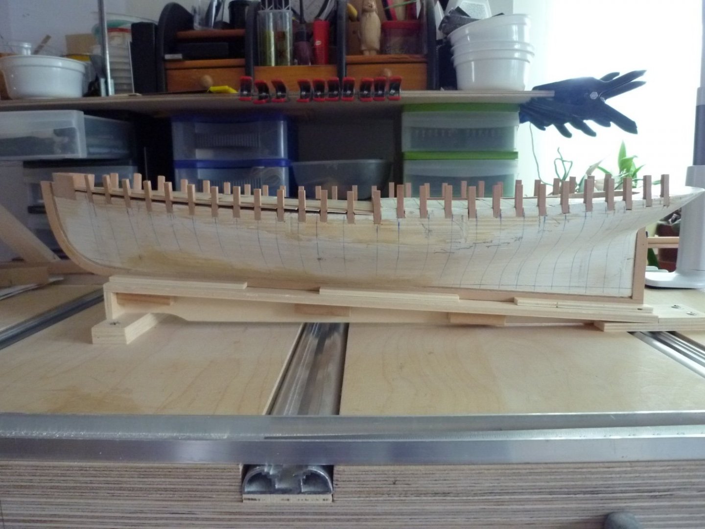
The bulwark stanchions are perpendicular to the construction waterline, not the keel line.
 D1
D1
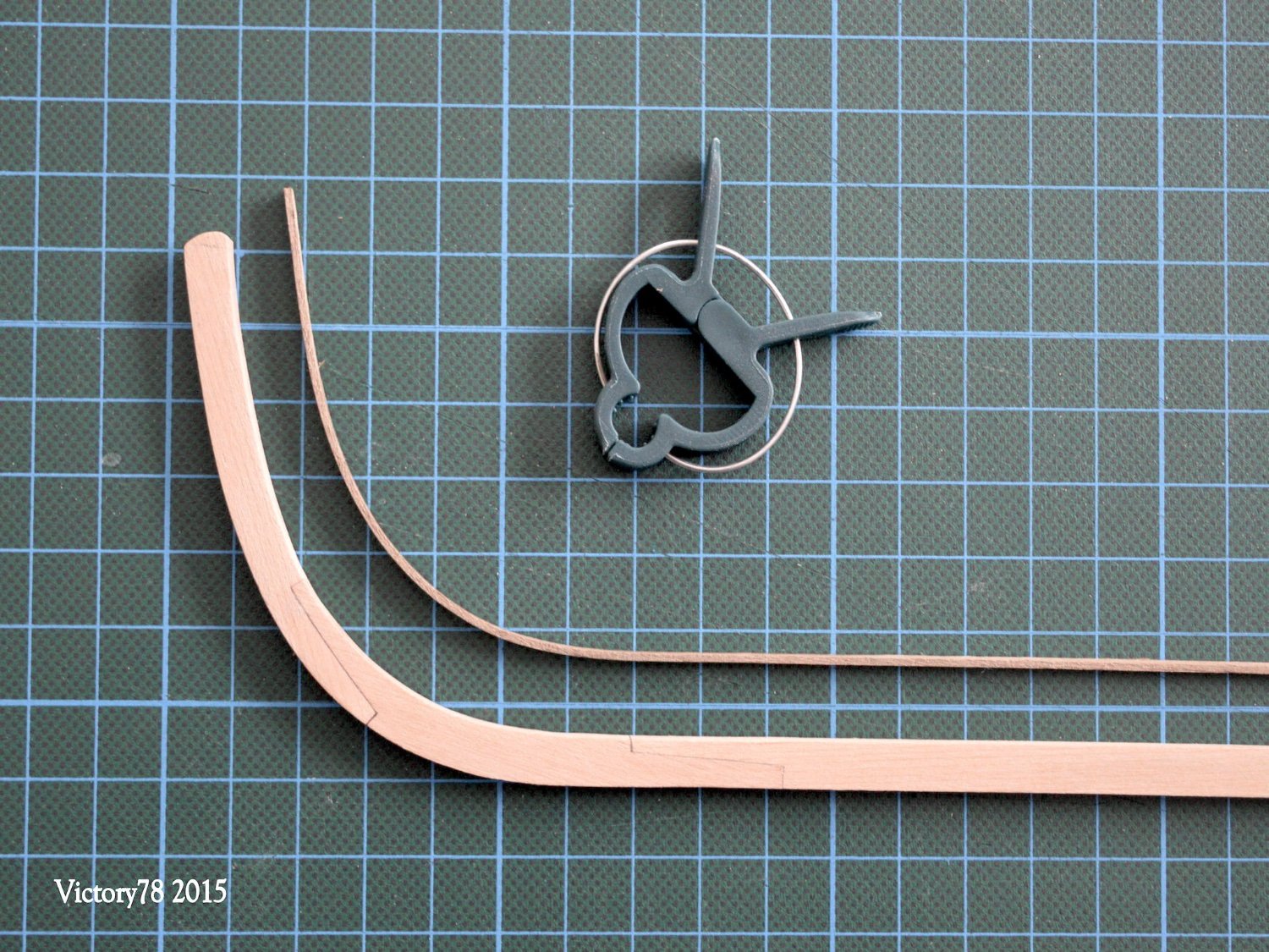
The Timberhawse at the bow consist of several glued parts.
The contours for the waterway were taken using a template. The Waterway was made from 1 mm pear wood boards. Step by step, the individual parts were shaped with a file.

The bulwark at the stern was made from several pieces of wood and was shaped with a circular sander.

The frame of the rudder cockpit was laminated from 3 layers of pear wood veneer. A mold had to be made for this.


… now the decks could be planked.
bye for now
- berhard, bolin, Mirabell61 and 7 others
-
10
-
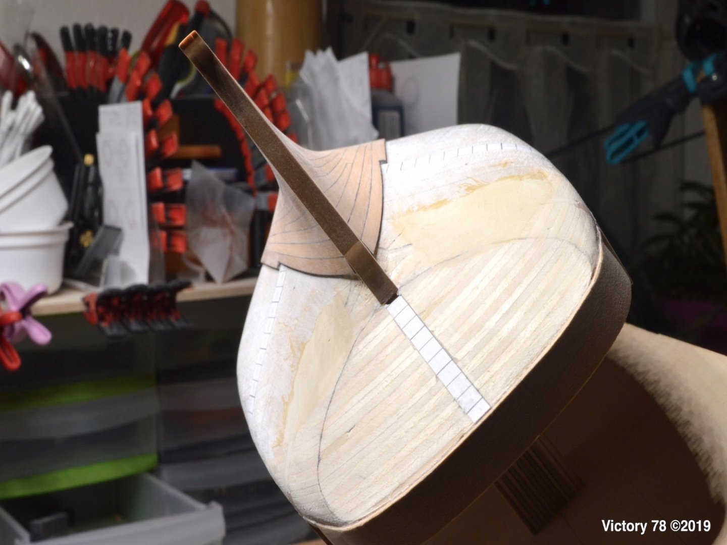
Hi, everyone,
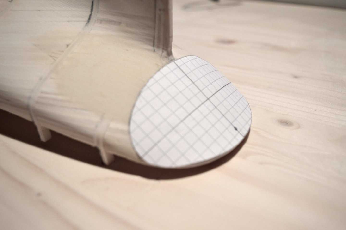
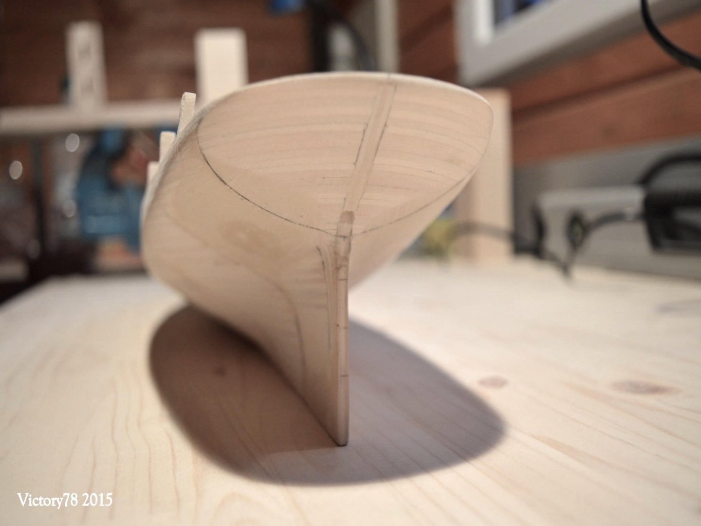
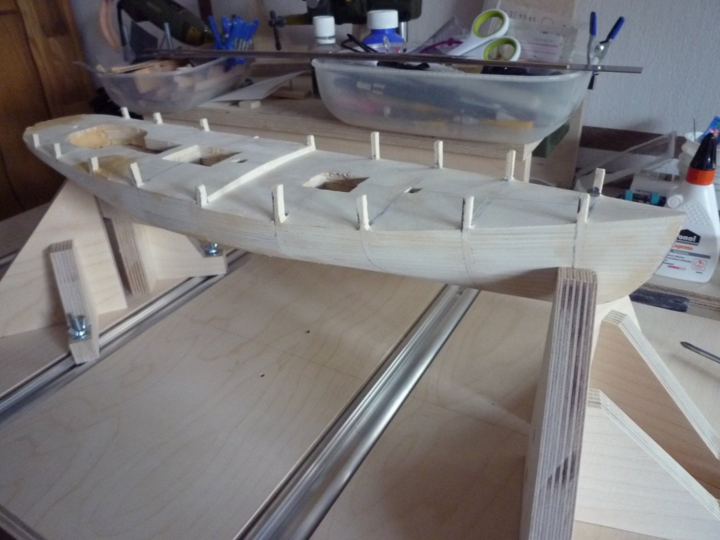
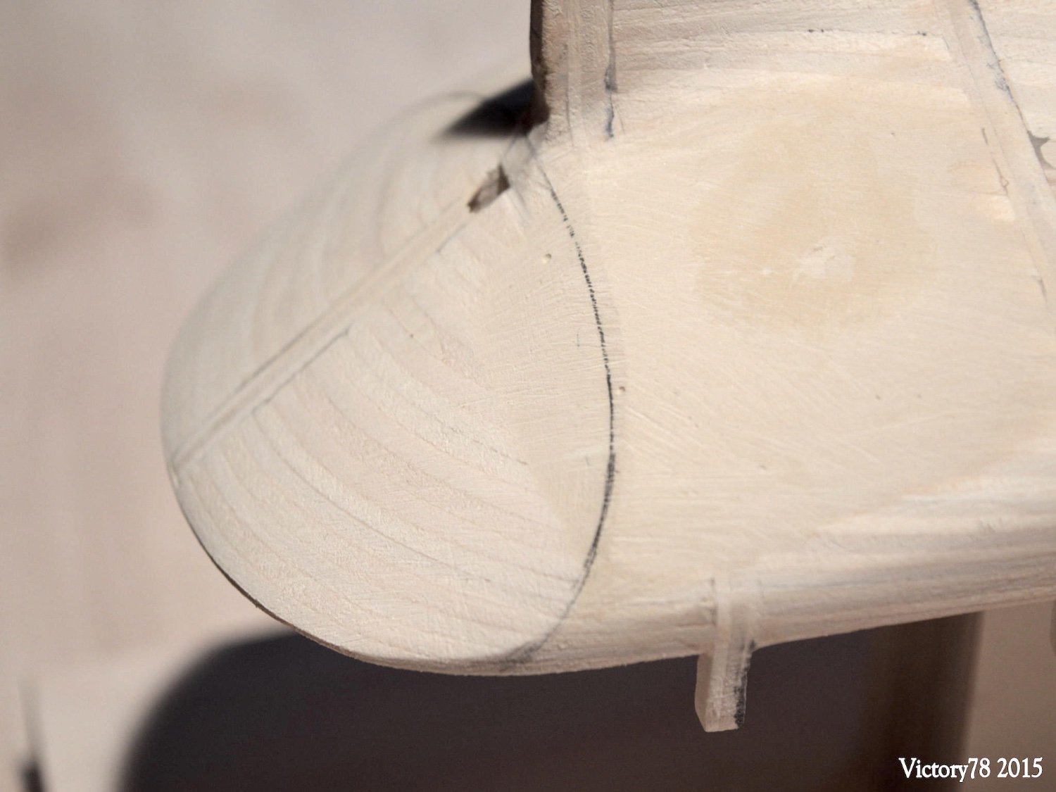
the ship's hull was turned upside down for the upcoming work. A small assembly stand is stuck in the openings of the companionway.
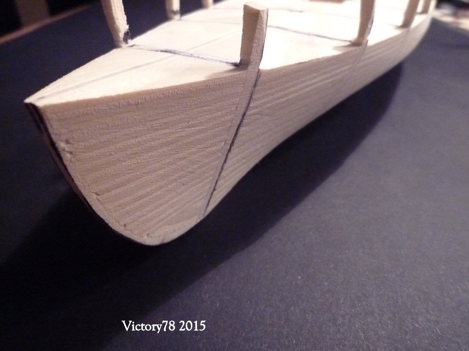
There is a slight kink at the transition to the star. The rear was designed with a cardboard template.
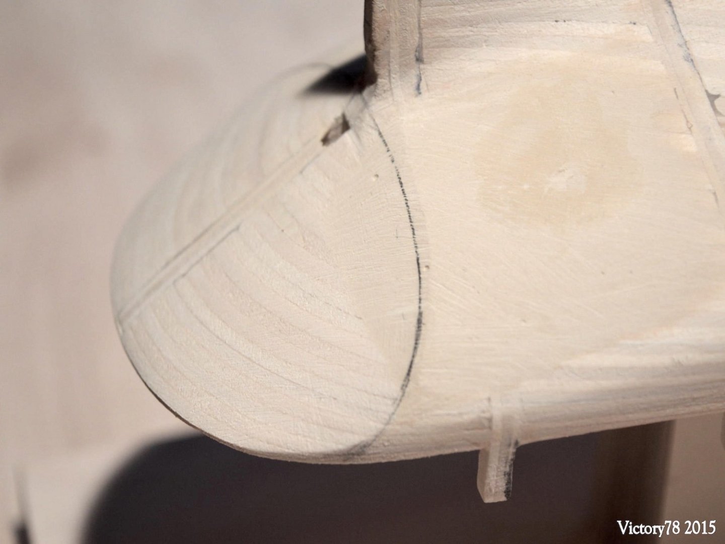
The Keel
The keel was composed of three parts of pear wood with Z-lugs. A sheet of glass is a good basis to get a straight keel.
A slightly narrower strip (3x1 mm) was glued to the inside of the keel. This creates a “false” keel scarph.

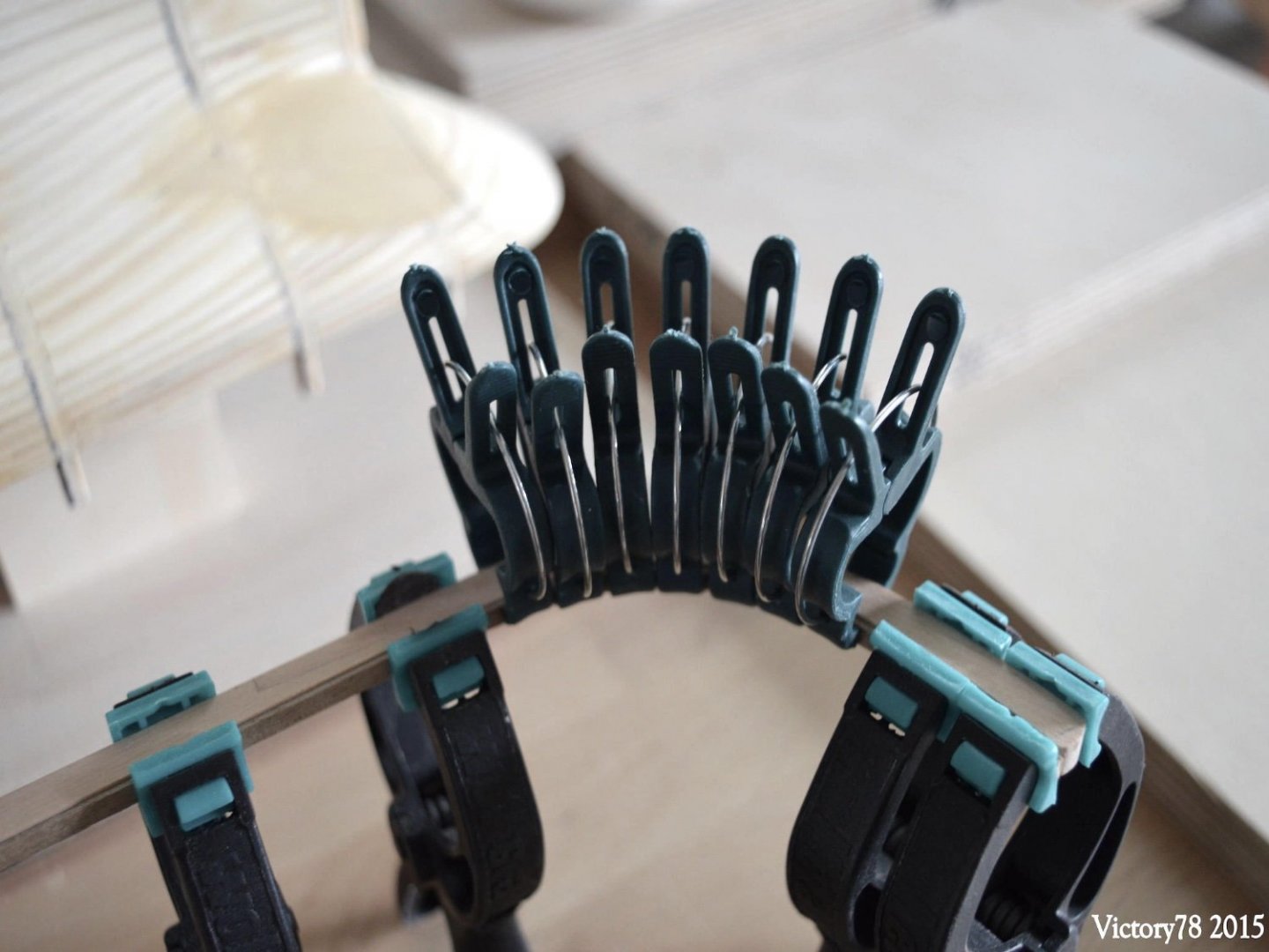
In the next step, the keel and stern post were pinned and glued to the ship’s hull.
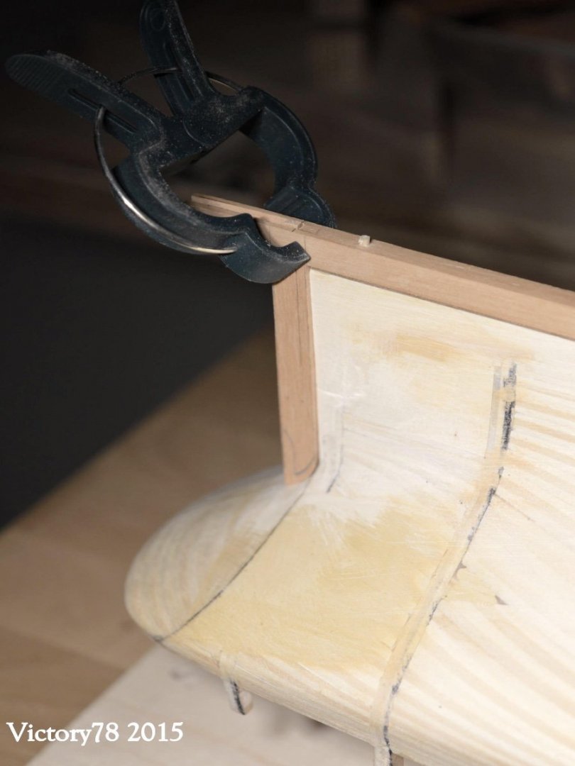

…. now we went to the decks ...
- ct mike, wefalck, GrandpaPhil and 5 others
-
8
-
On my LS PHANTOM I planked the decks outside the hull and then glued them in place. It's easier to do. -
Thanks for Likes...
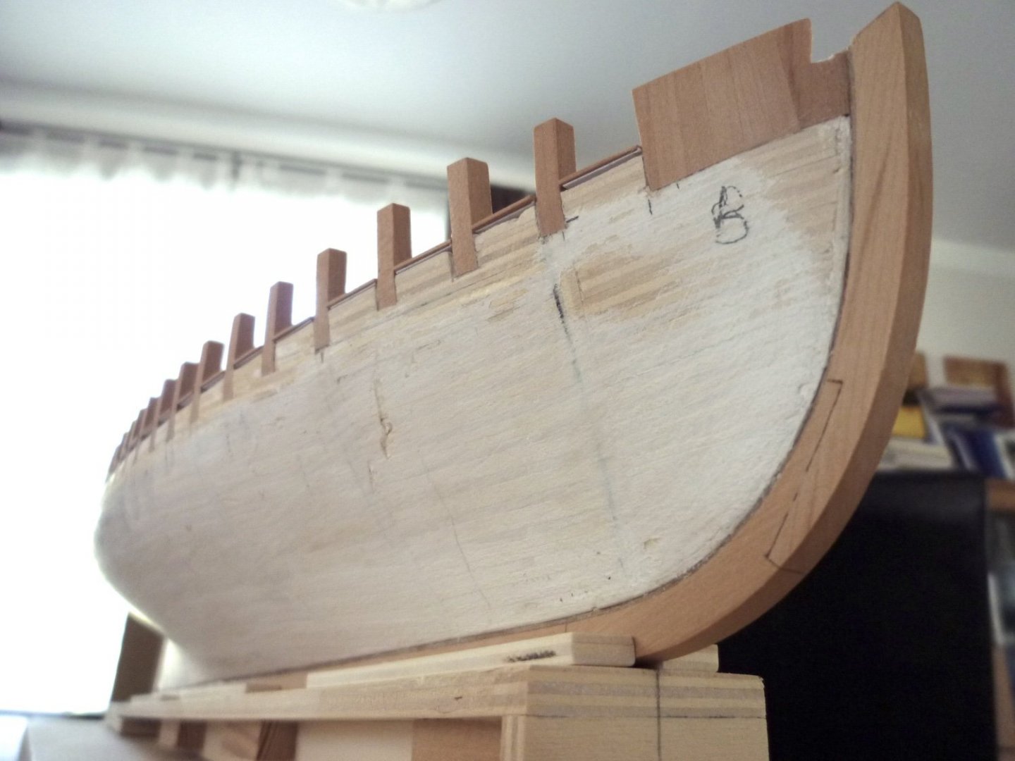
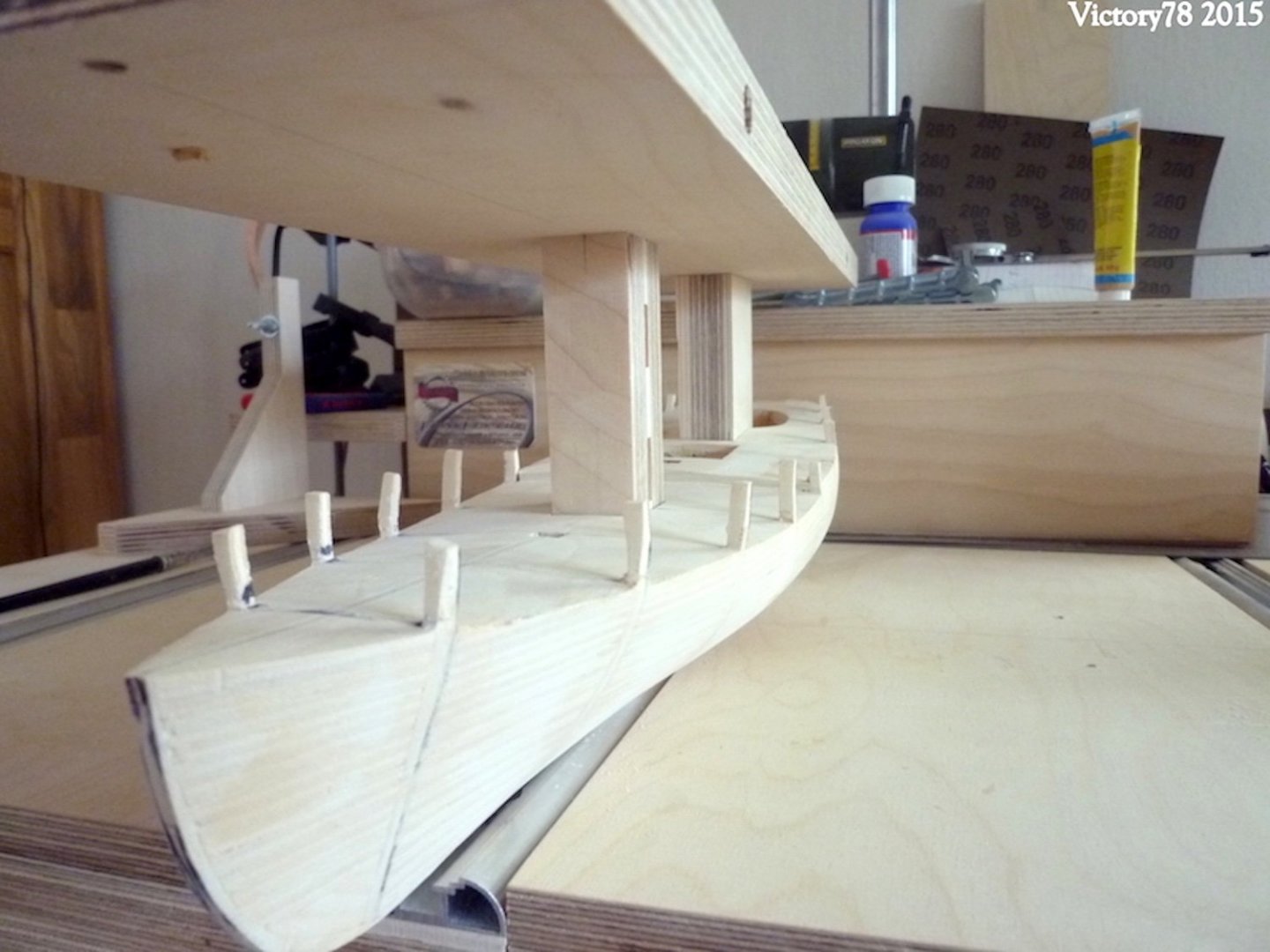
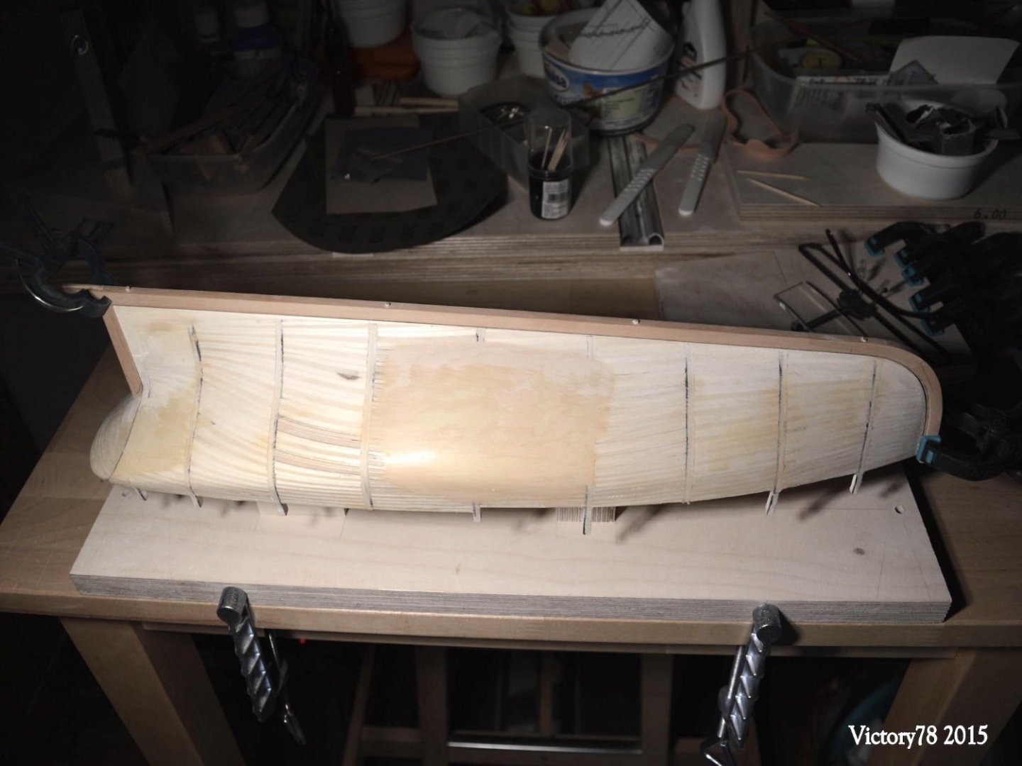
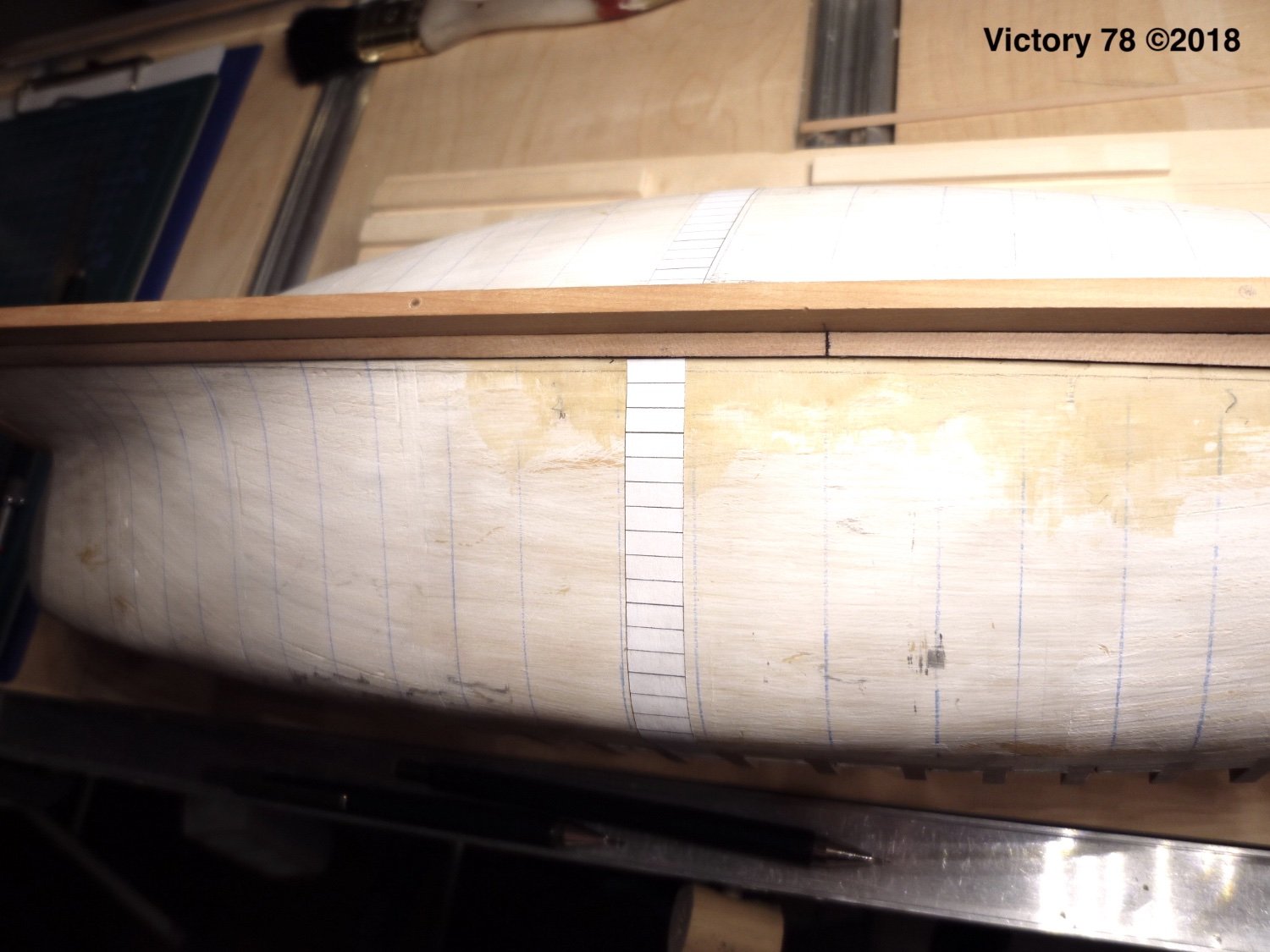
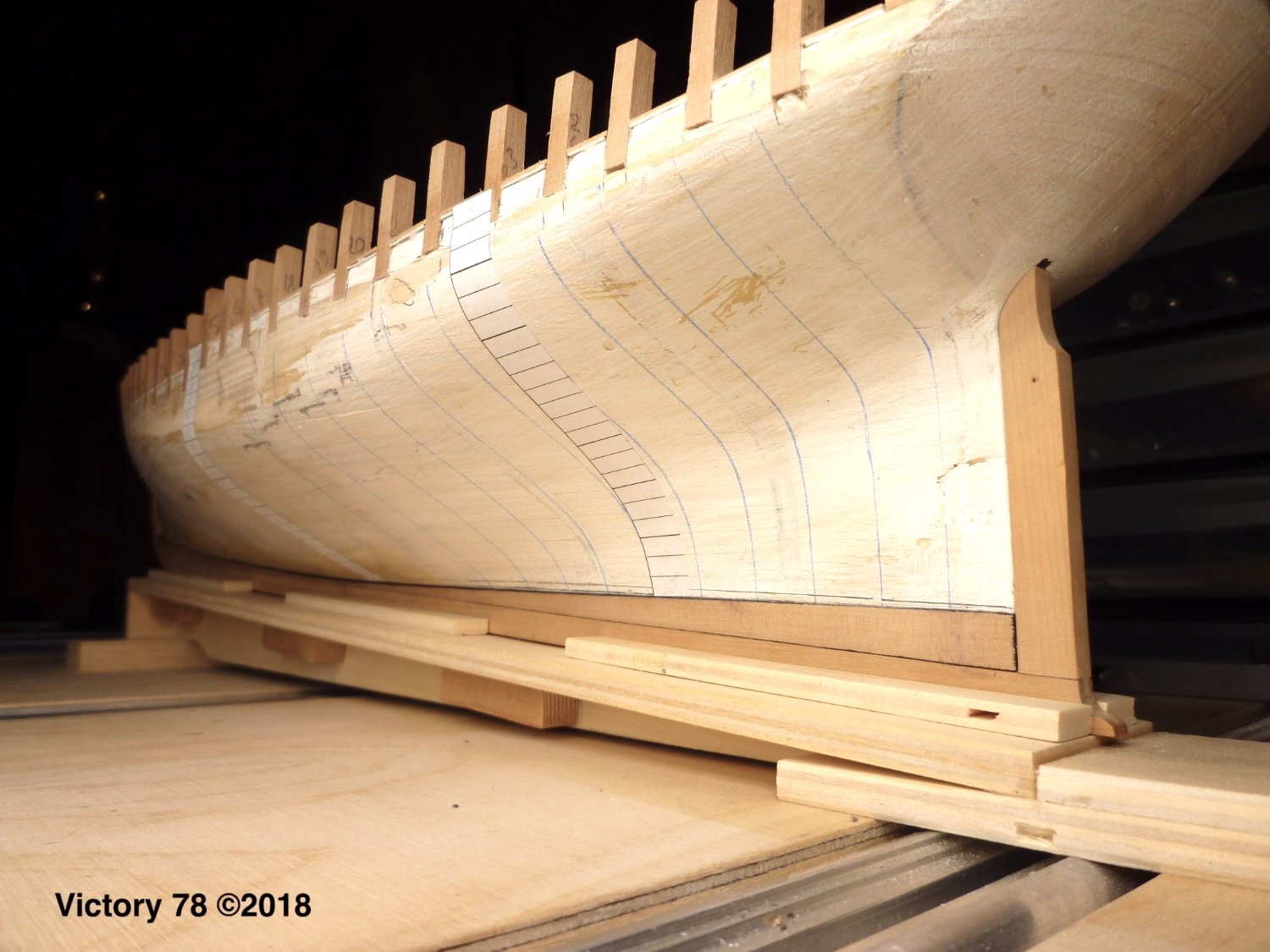
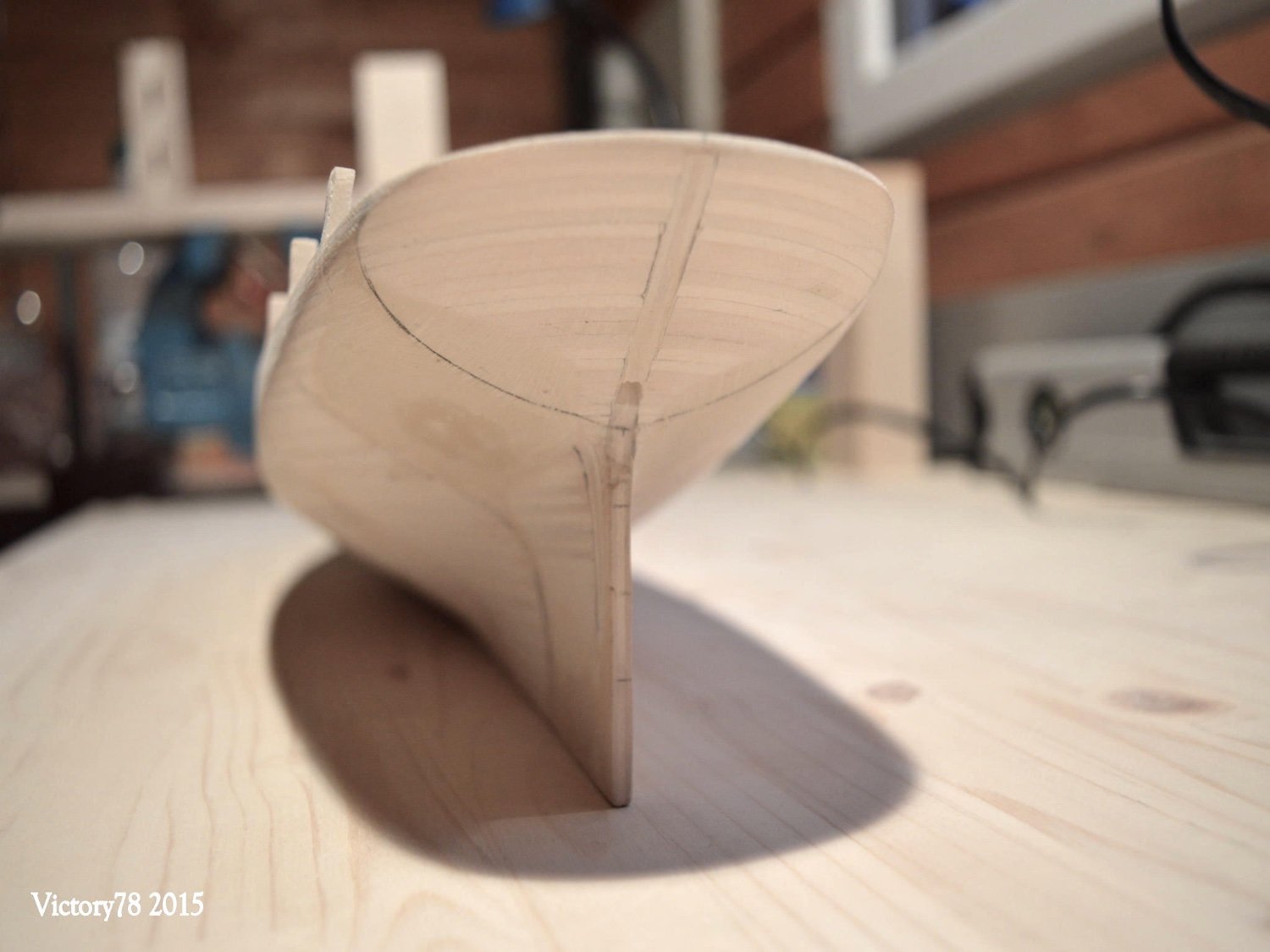
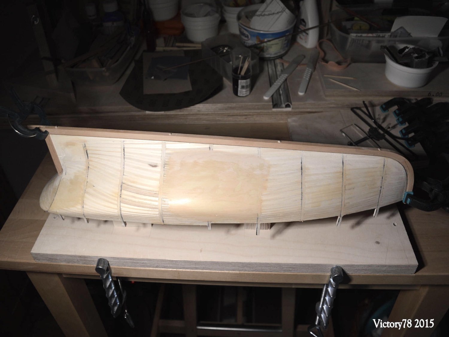
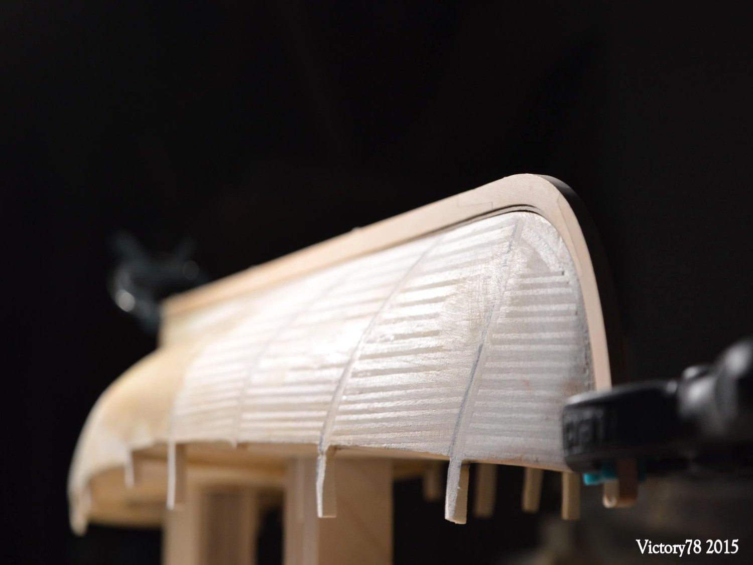
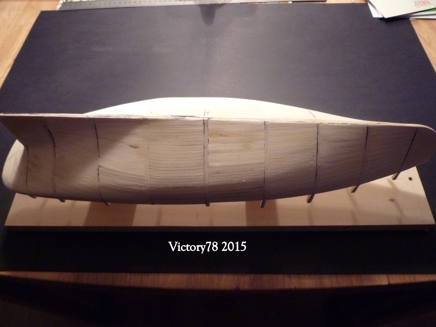
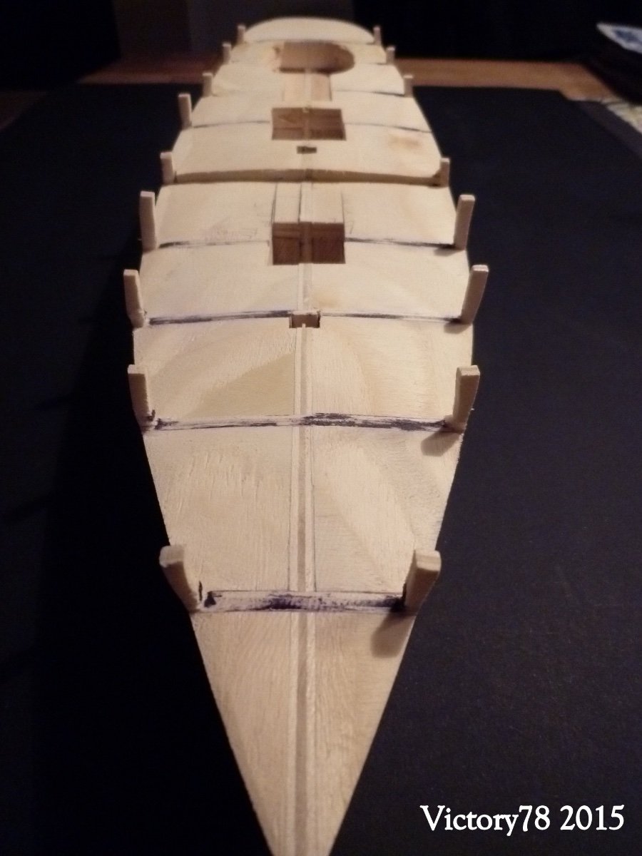
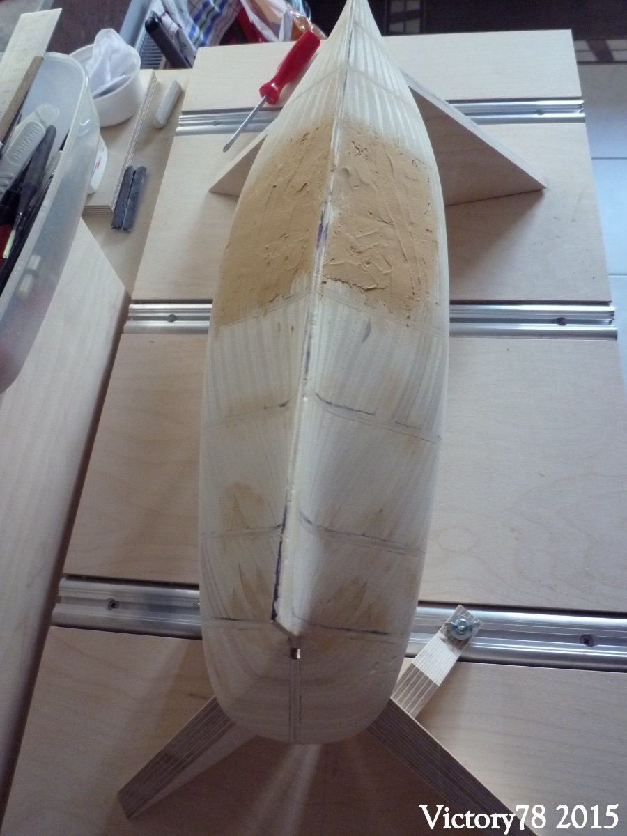
If the spaces between the structural frames are filled with waste (plywood multiplex), the result is a very stable hull. This can be planked directly. The excess wood is sanded off. In order not to remove too much when straightening, the edges of the structural frames frames are blackened (Edding). And now it was sanded.


The result is a beautiful, even hull. Some places were filled.The beamrounding was shaped.


The Phantom has beautiful lines. It goes on with the Stern.- KeithAug, wefalck, GrandpaPhil and 2 others
-
5
-
-
Hello everyone and best regards from Berlin - Germany.
I registered at MSW in July / 2020, but haven't gotten around to being active so far (pandemic tribute ?), but that should now change.
I've been at home in model making for many years. After various kits from Revell (all of which did not survive the times) I came to the wooden sailing ships and made the mistake of reaching right up to the top and began to build the HMS Victory (kit) in 2000.
Dissatisfied with the kit, I stopped it and started a new beginning in historical ship model building.
7 years ago I started a simple fishing boat "Zeesboot" around 1920 to improve my knowledge of materials and tools. At the same time, I started another model in 2015, the pilot boat “PHANTOM” (1868) in a scale of 1:50. I am building this ship in a group of model builders.
Even if some time has passed, I hope to show and pass on some inspirations and techniques with a building report. I am looking forward to a great time with all of you sharing knowledge and practice. I already know a few names here and I really like what I saw about the pilot boat “PHANTOM”. If there is time and interest, a report on the Zeesboot is also possible.
BtW; my english is not really good but the google translator should help me here.
So excuse my writing style. Of course, I am happy to answer any questions.
***
The result is a two-masted gaff schooner for the New York Lotsn; a service ship of the port authority. Built in 1867 in East Bosten (Massachusetts) by Dennisen J. Lawler and sunk in 1888. Half a century later by H.I. Chapelle published cracks and their revisions, a 3-part blueprint is available today. The planning documents and the book “Working techniques for ship model building” (Robert Volk / Peter Davis Garner; ISBN 3-88180-704-7) are the basis of this ship model. So it is not a kit and all parts are made by ourselves. Robert Volk, one of the authors, accompanies the group project and gives valuable first-hand information.
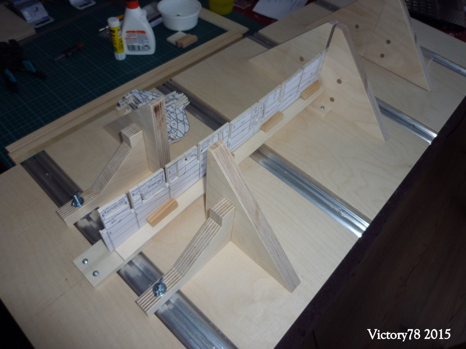
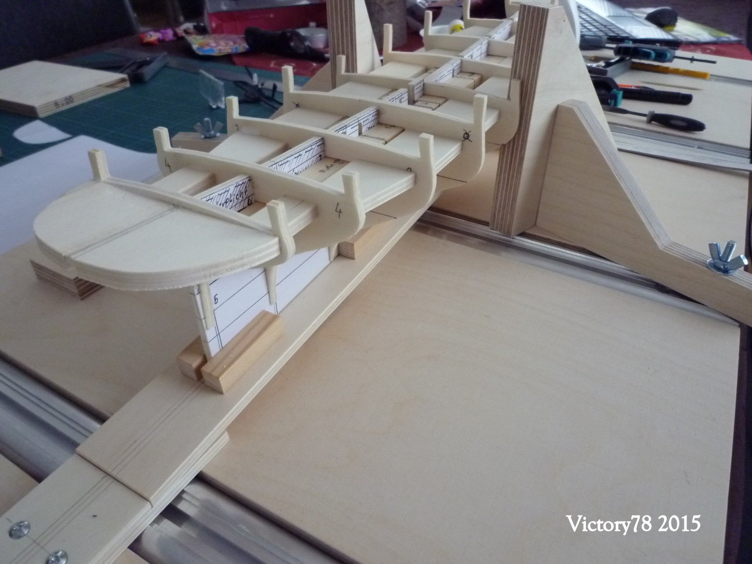
I want to start with the "slipway" because there was none available for this model.
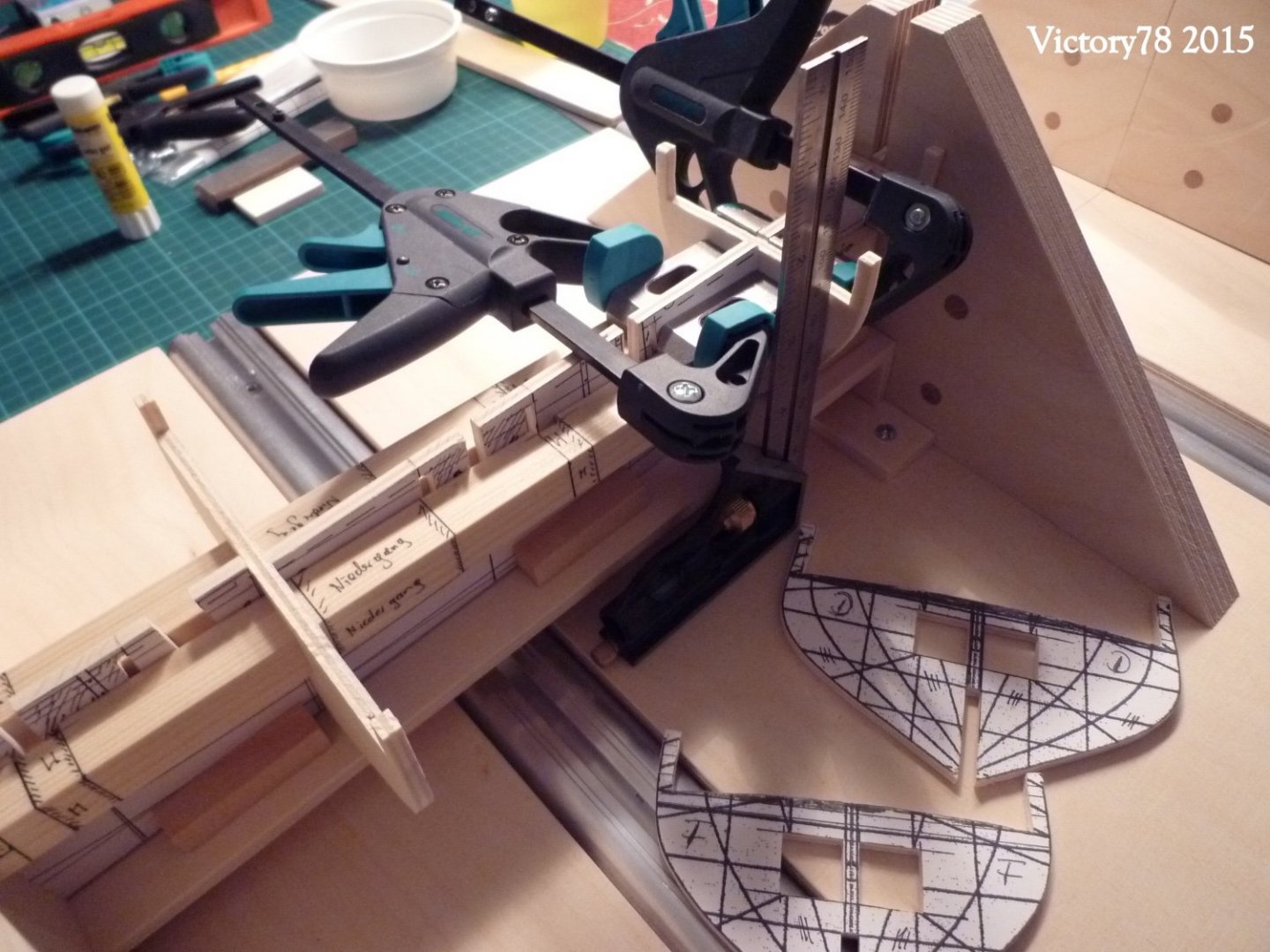
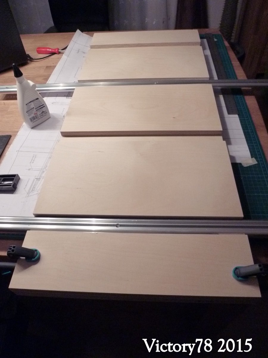
Inspired by the slipway presented in the project, I first built the following base:
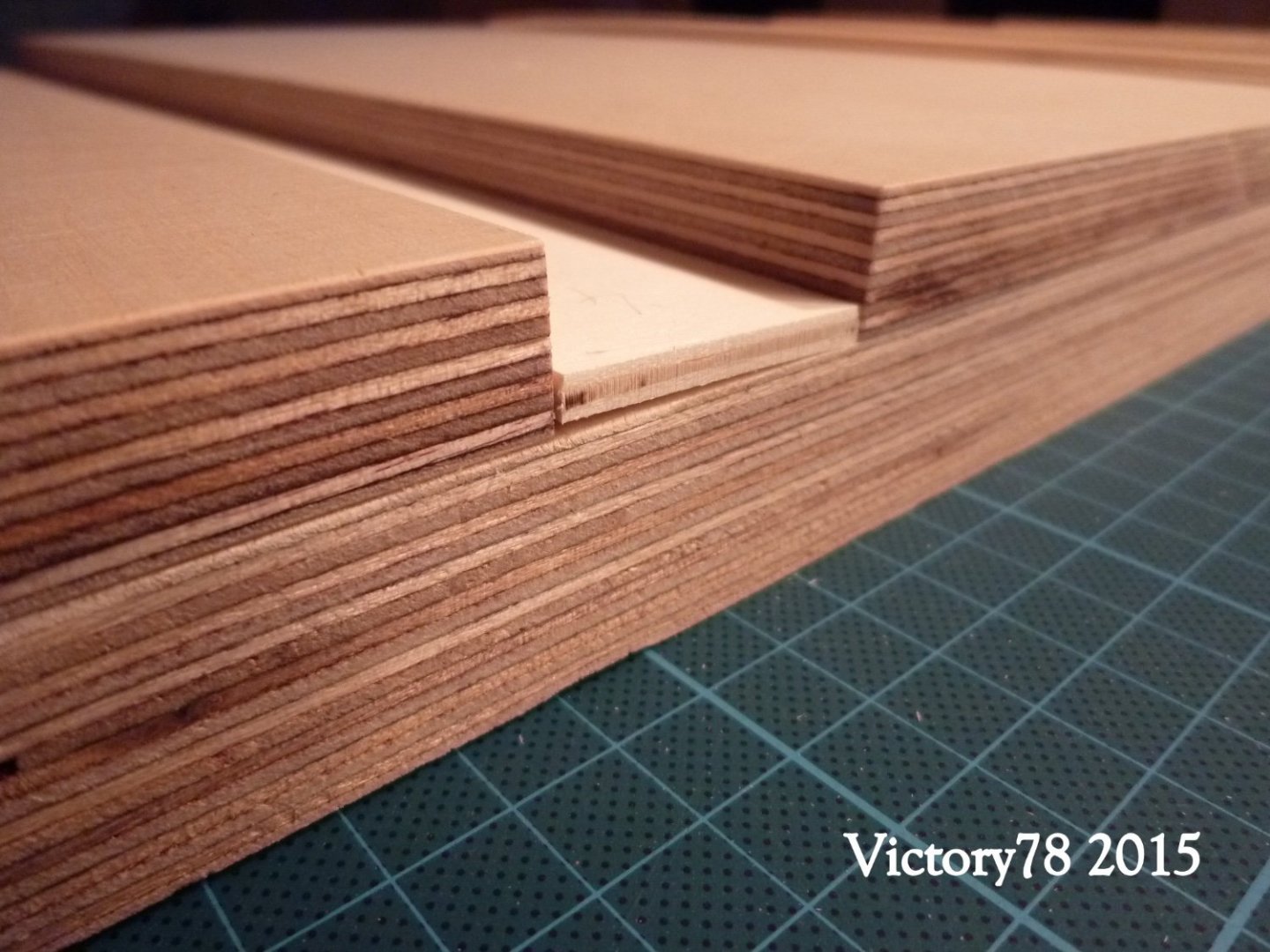
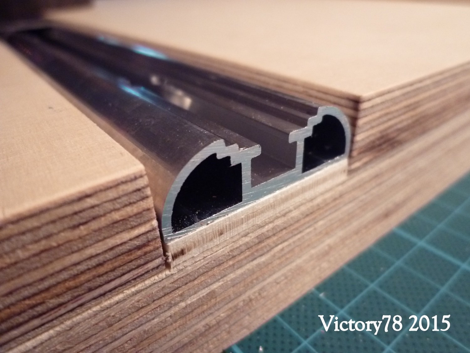
12 mm multiplex segments were glued onto a 25 mm multiplex board (950 mm x 400 mm). As long as the shipyard is dry, multiplex panels are absolutely free of distortion and are thick enough. A profile rail was screwed into each of the spaces. This ends flush with the surface.


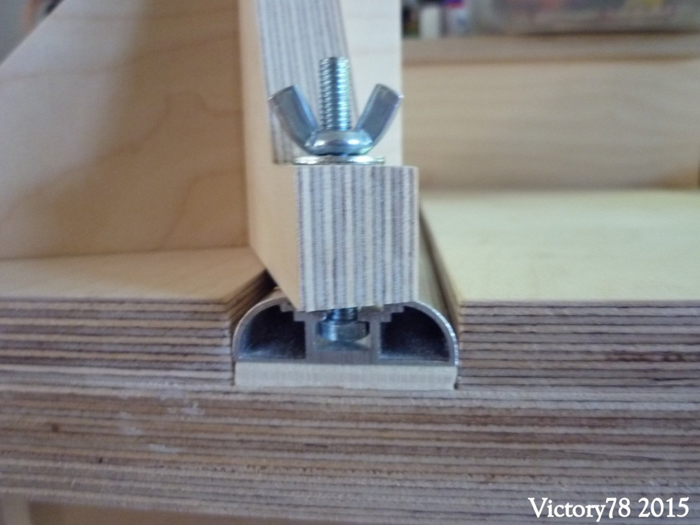
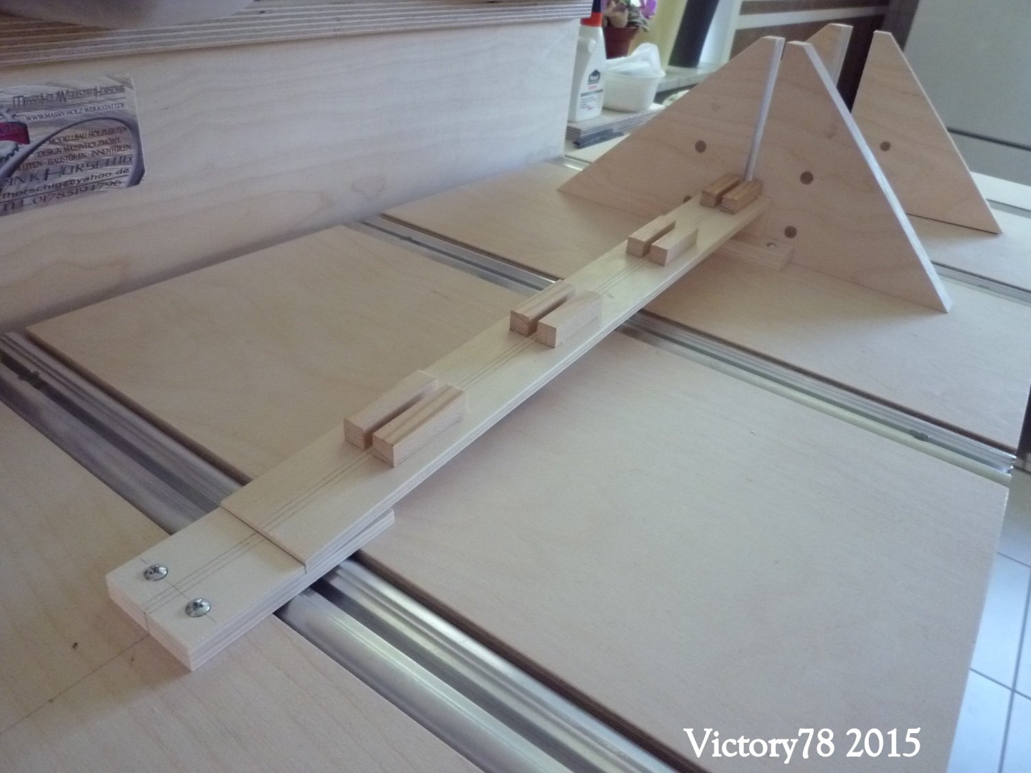
Various support brackets can be mounted in these rails. These are connected to the rail with an M5 machine screw and wing nut and allow use in the transverse axis in 4 positions and at any point.
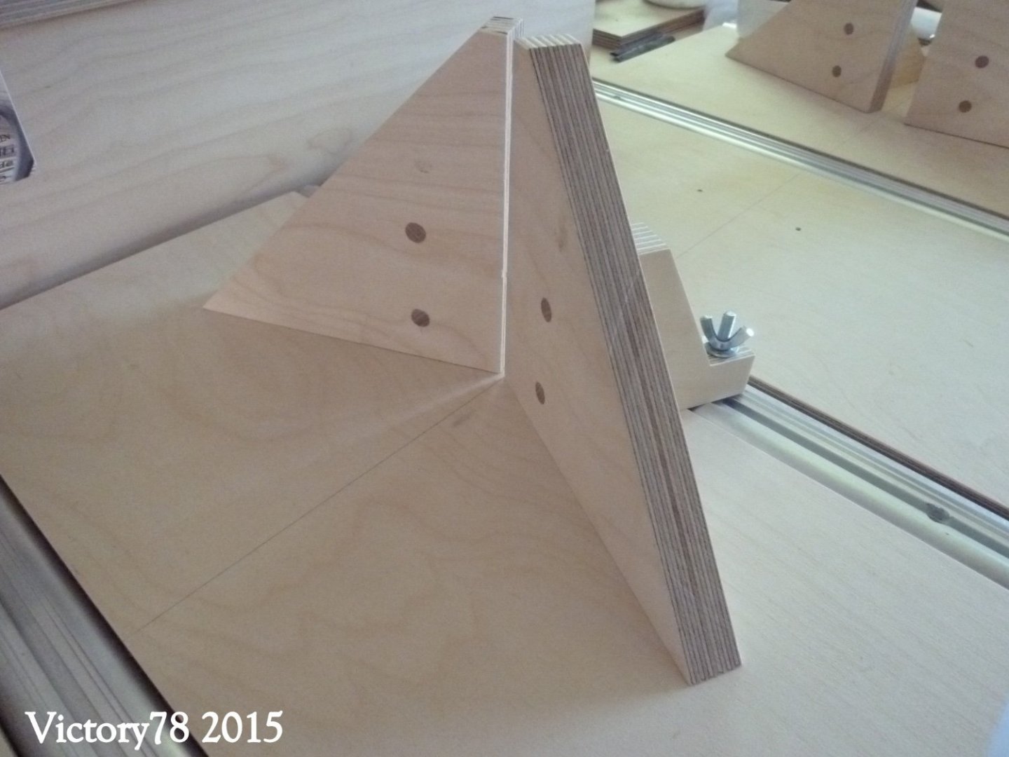
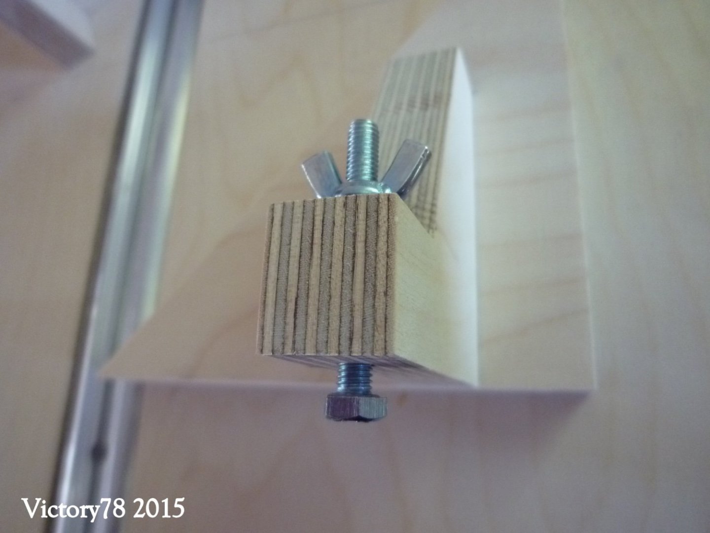
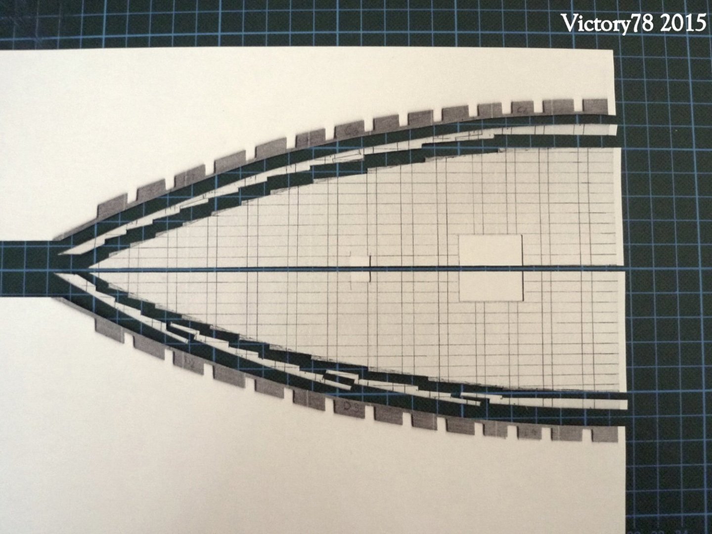
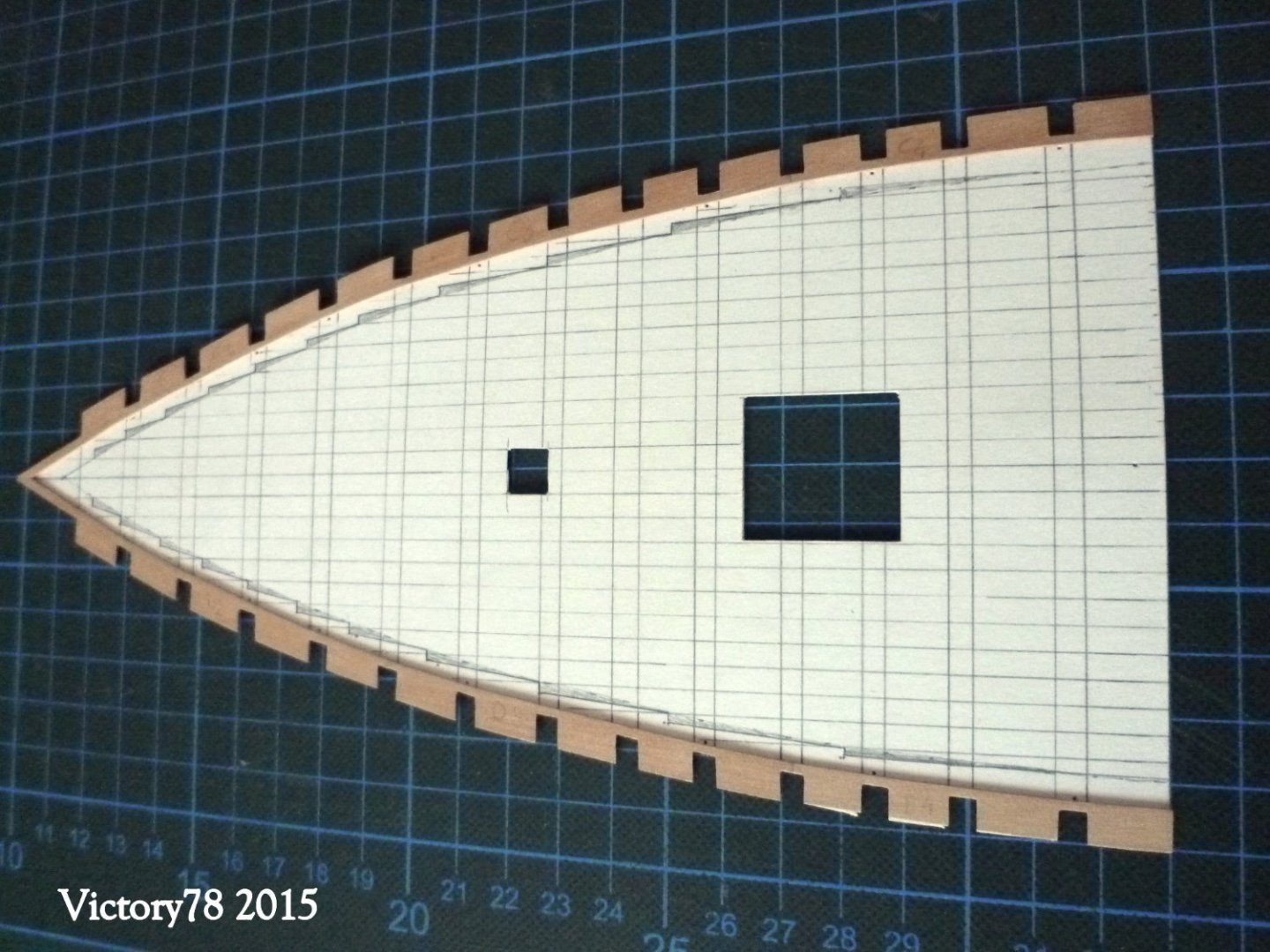
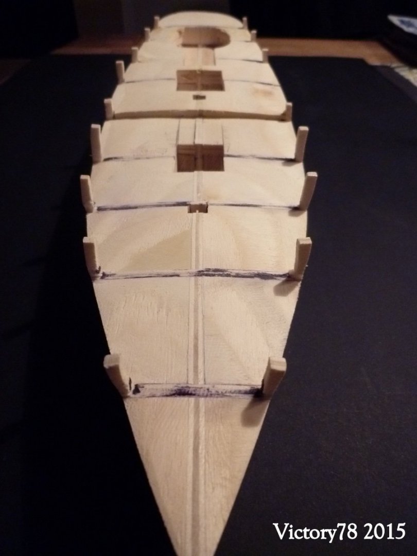
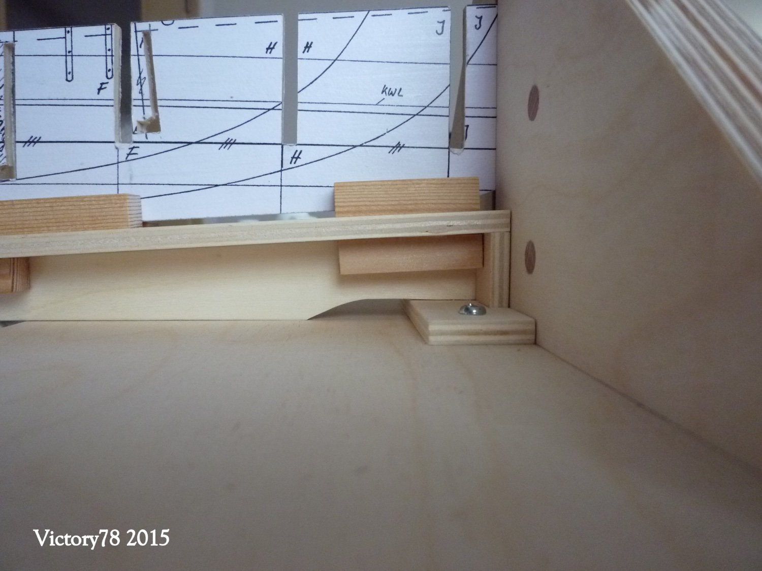
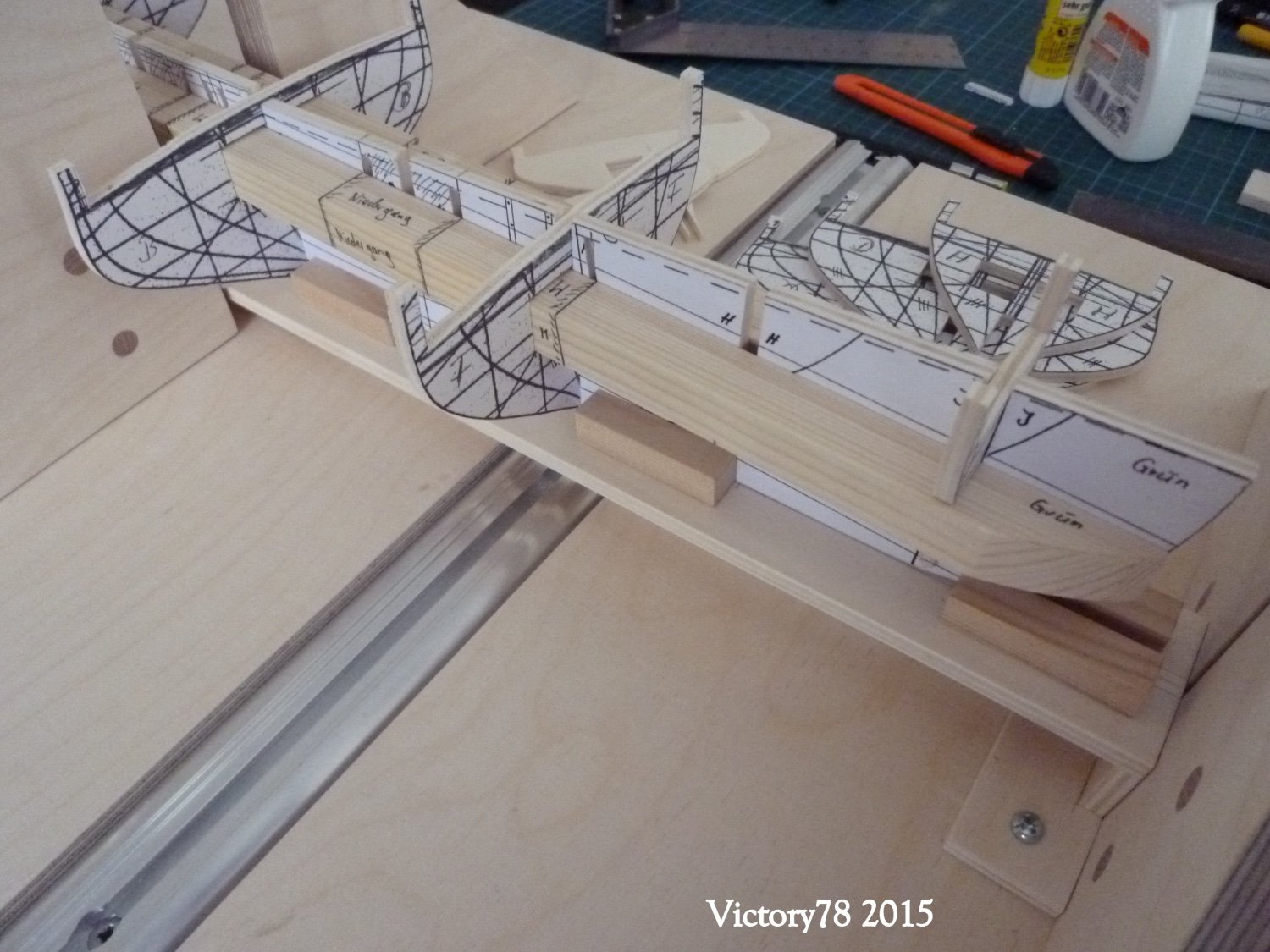
Later on, the U-rails for a “measuring bridge” will also be held in this way. The hull was then mounted on this slip board for the stern fall (the keel does not run parallel to the waterline). So the first step was done and we could start. The templates of the model frames were made available in a separate file. The set consists of the middle part and 9 structural frames. Two strips (10 x 10 mm) run along the center board / frame for stabilization on the port and starboard side. This prevents the central part from warping.


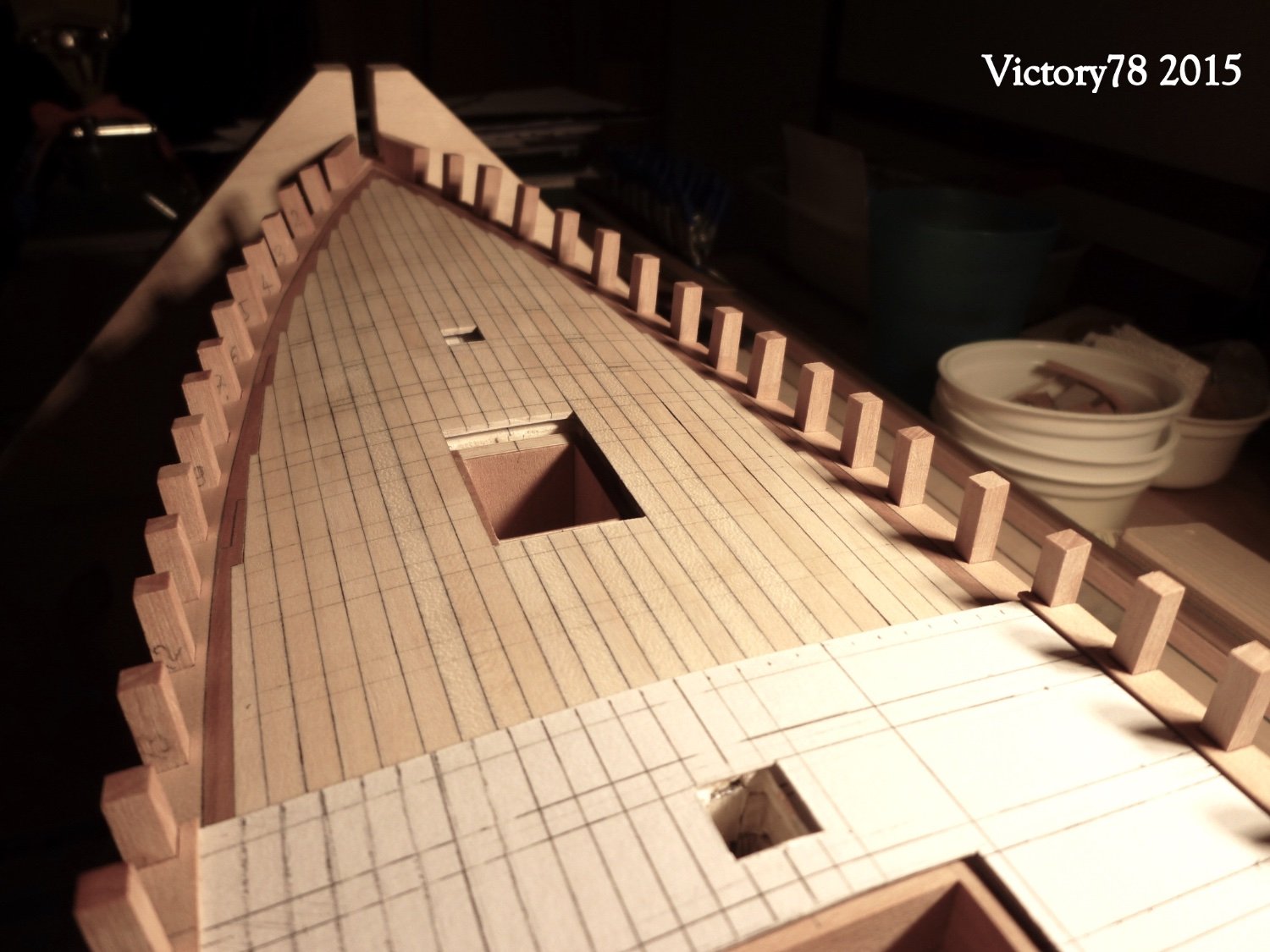
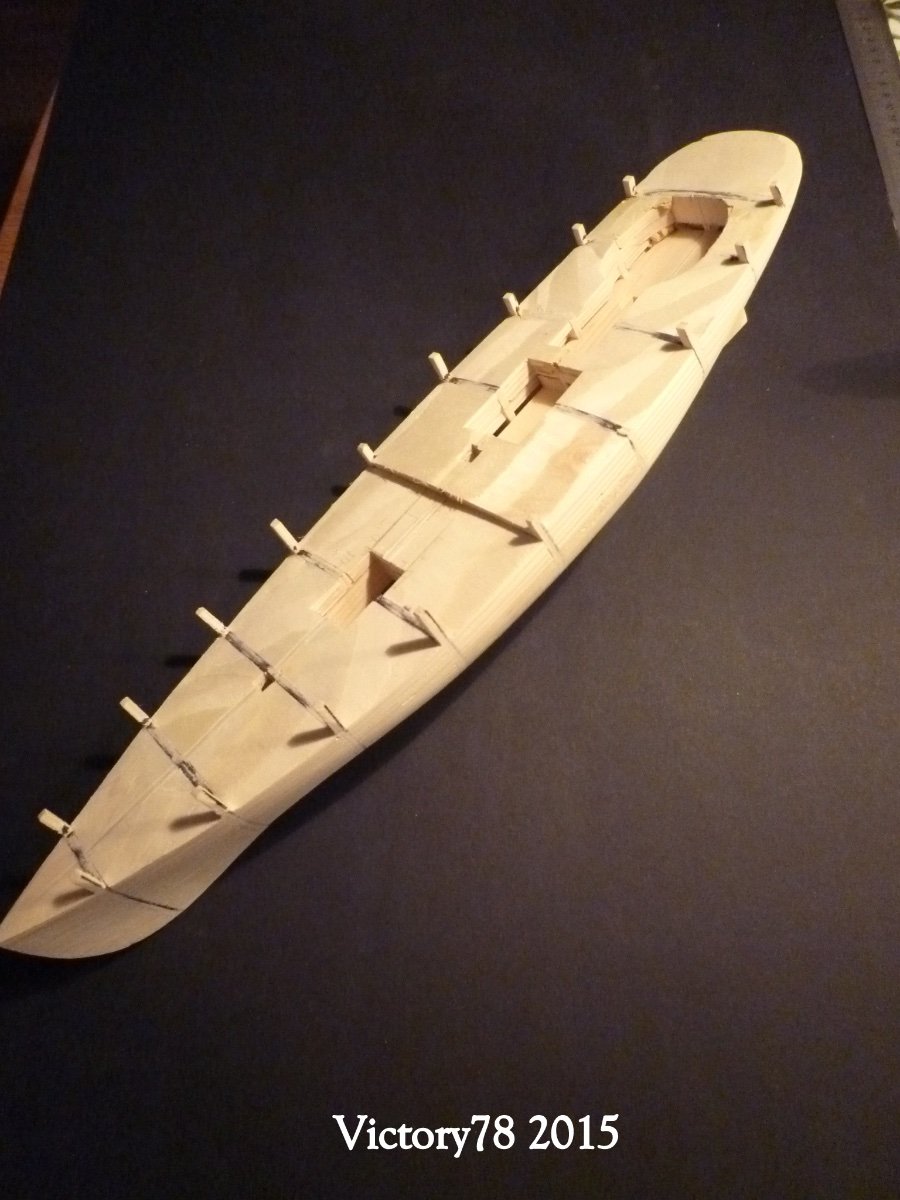
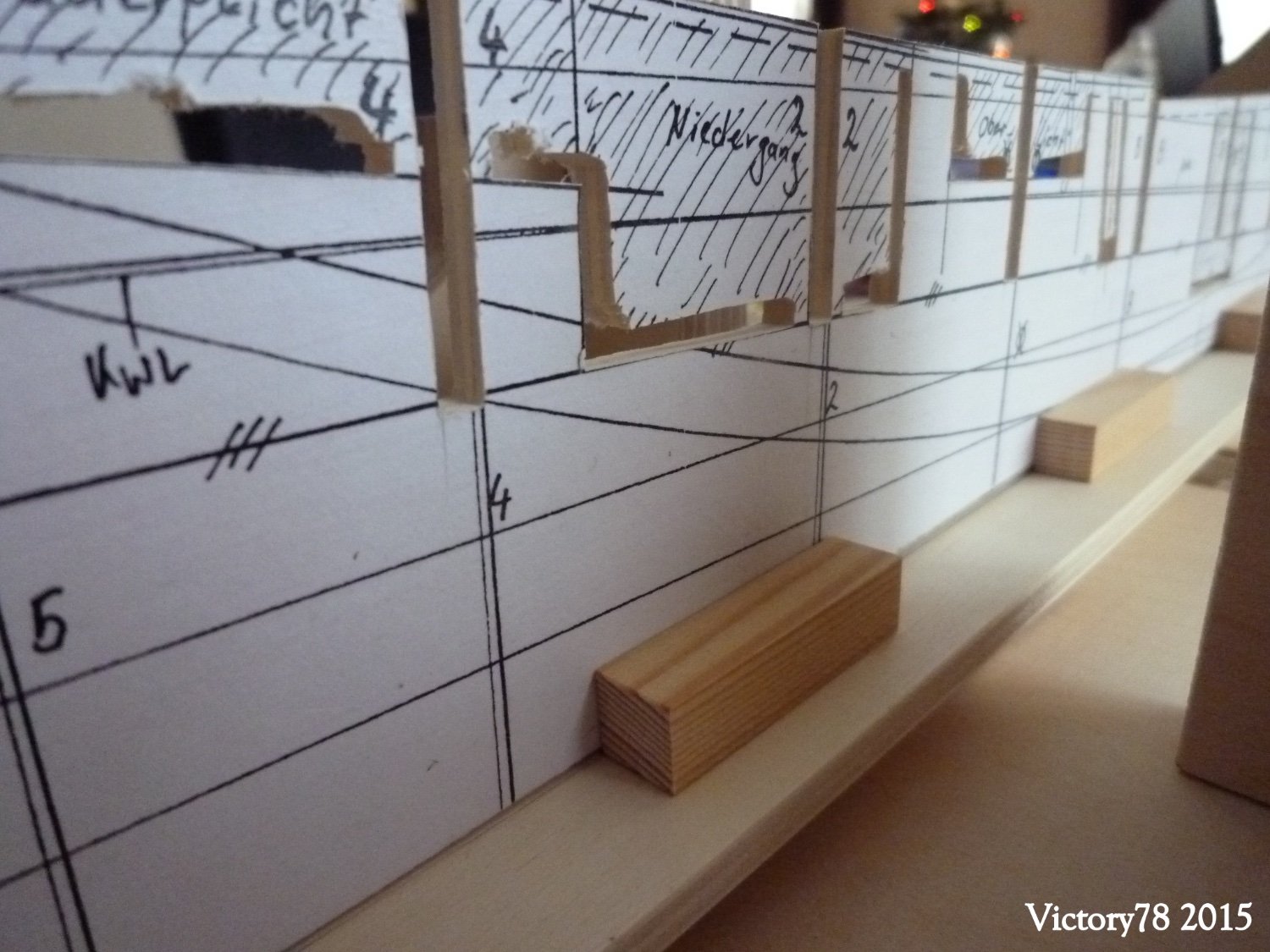
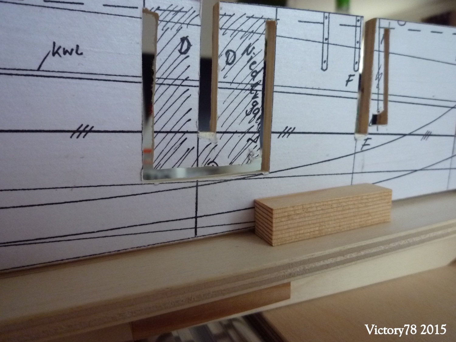
I have already sawn out the cutouts for the companionways, the masts and the oar light in the lower area and left only a small jetty. So I was able to break out these parts after gluing the ribs with the middle board and the reinforcement strips.

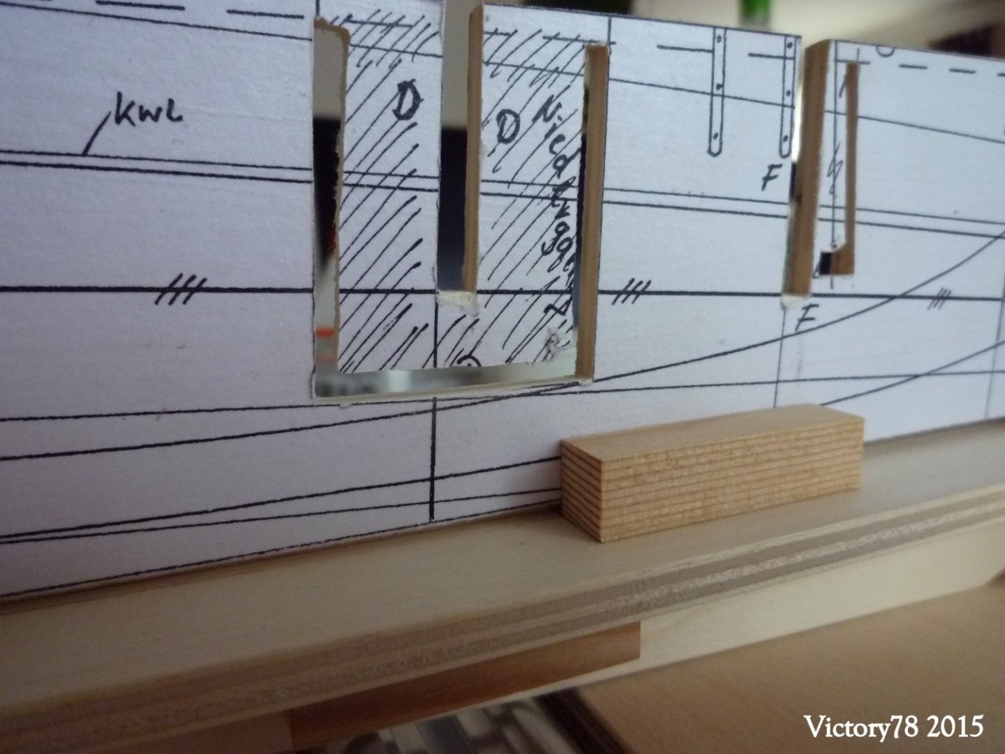

The construction of the bulkheads (malls) was now ready and it continues with the hull.
-
Hello Nils, thank you. I posted some impressions of my boat in the welcome chat. I'm not sure yet if I'll post something like a report. A lot has already come together. Sometimes there is not enough time. We will see.Greetings Matthias
-
Hello Nils,I am also curious to see when the boat building will continue. If it takes time, I'll be happy to wait. Stay healthy.
Greetings Matthias
- mtaylor, Keith Black, Mirabell61 and 1 other
-
4
-
Very interesting boat building, it was certainly not easy to seal this. Greetings Matthias
-
3 hours ago, Dannebrog Mod from Biiling said:
Welcome Matthias!
Don't worry for your writing Style. Wir können auch auf Deutsch kommunizieren. Regards from Spain!
")
Hello Miguel, @Dannebrog Mod from Biilingmy English has to improve.
-
-
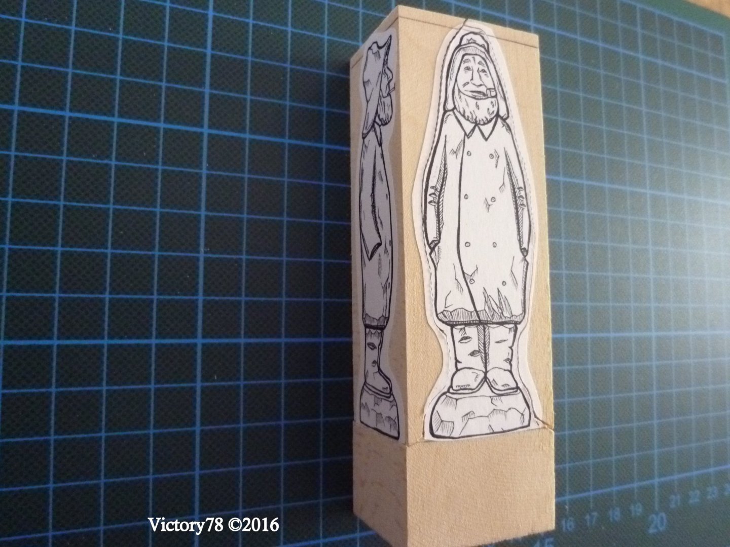
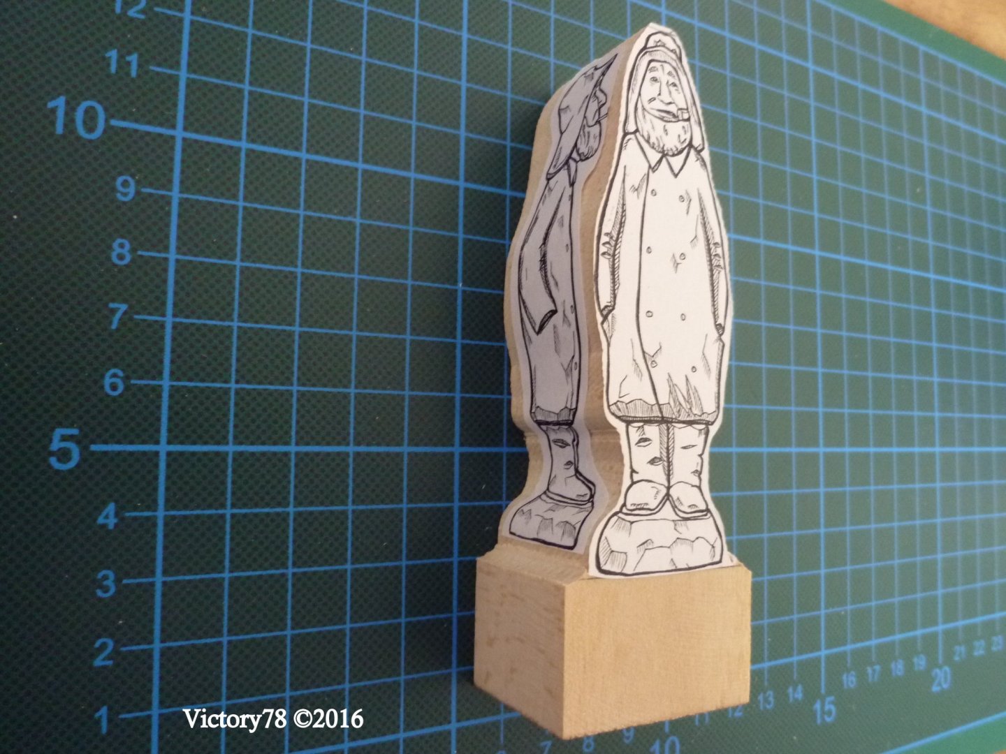
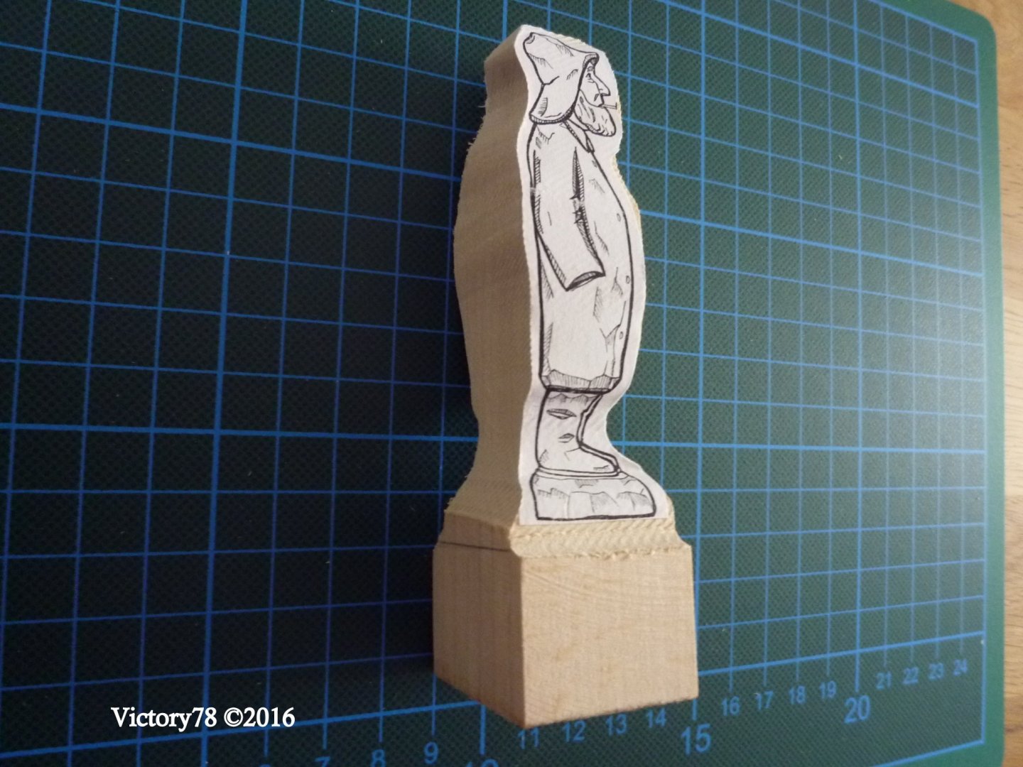
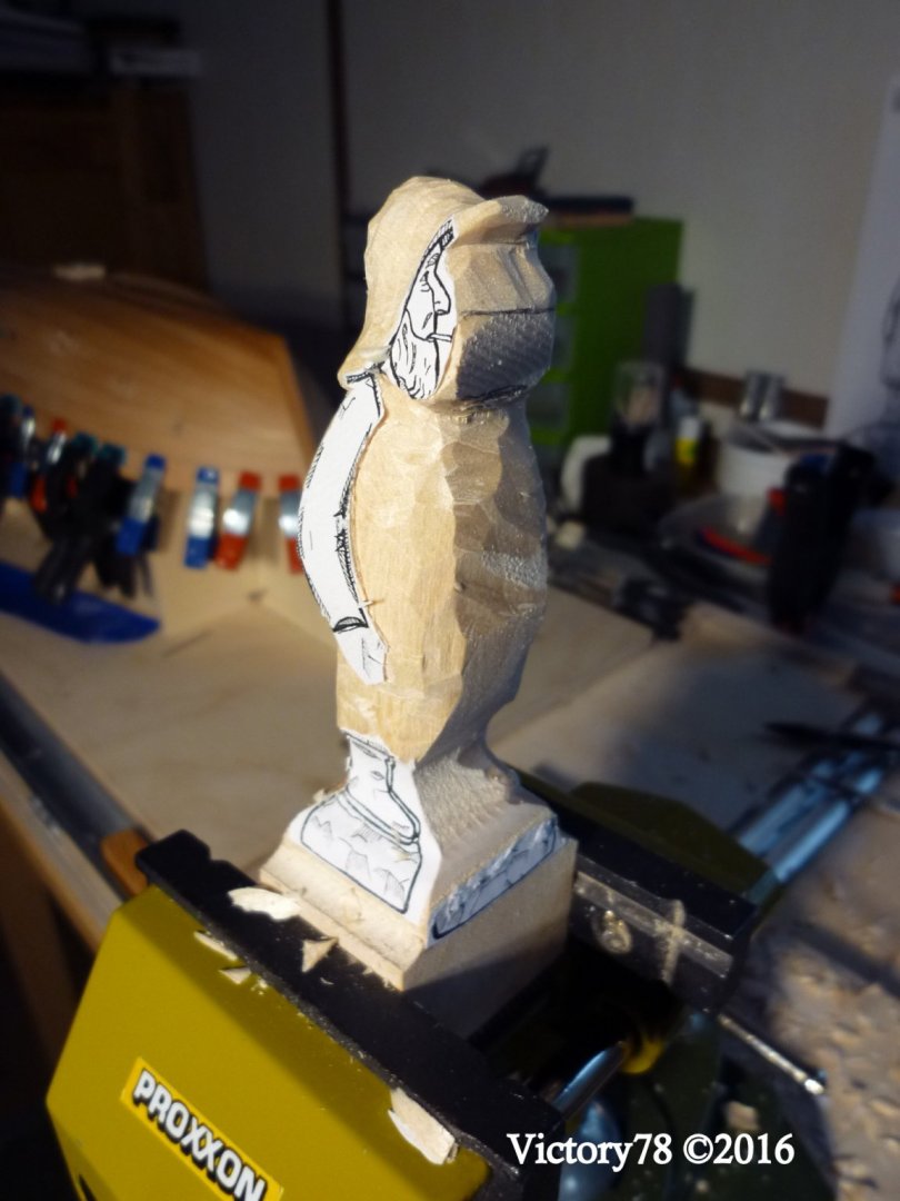
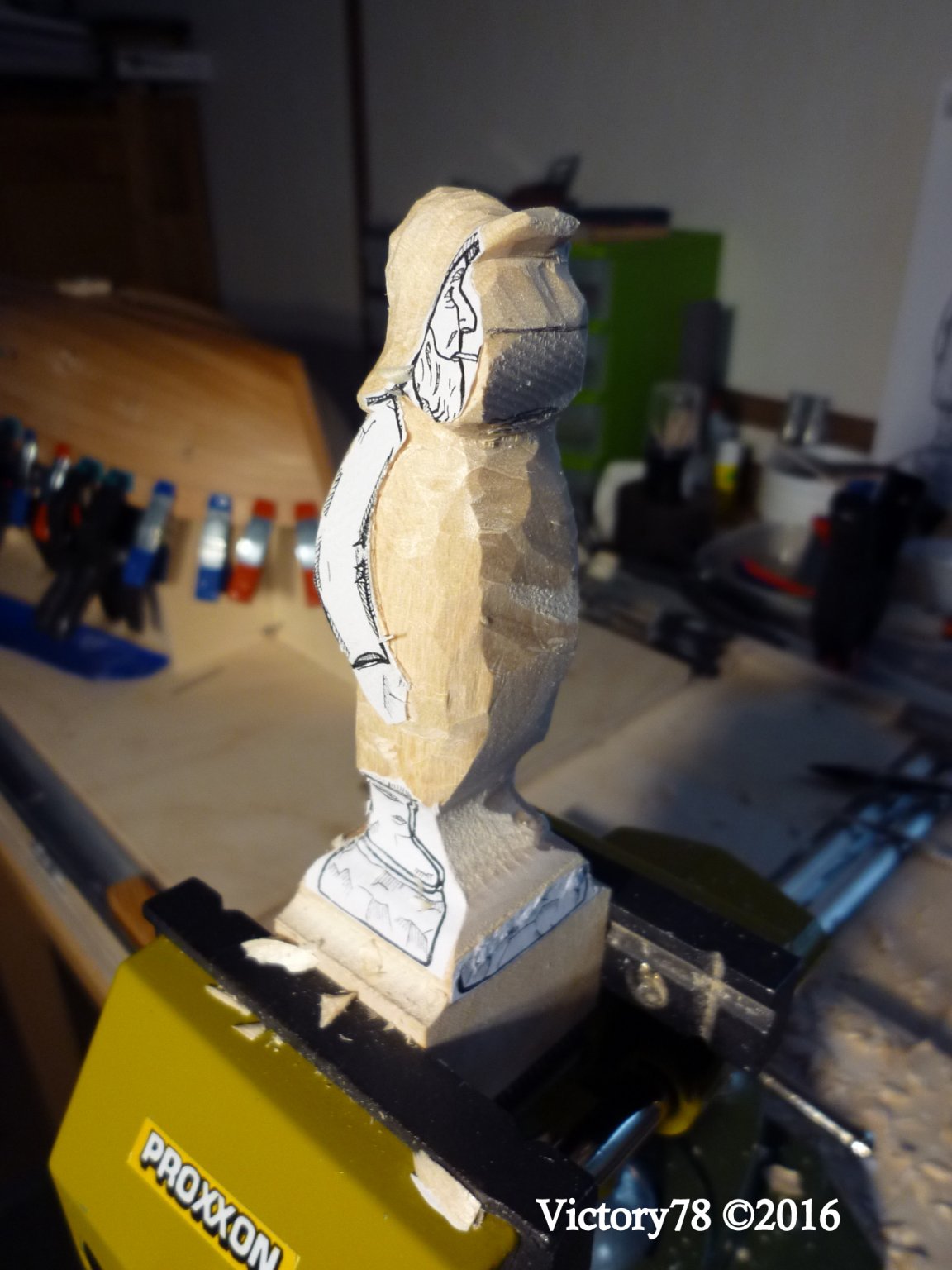
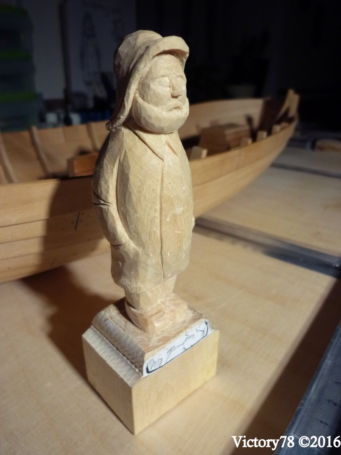
Hello Steven, @Louie da flyLimewood is not very hard. It is ideal for practicing. The burl is still ok up to a scale of 1:50. Then boxwood is better. Here is the block I freed the captain from.

-
Welcome to MSW, Uwe.
- Ryland Craze and mtaylor
-
2
-
Hello Oliver, nice to meet you here too. Great progress.Greetings Matthias
- Oliver1973 and mtaylor
-
2
-


Phantom 1868 by victory78 - New York pilot boat
in - Build logs for subjects built 1851 - 1900
Posted · Edited by victory78
Hello  Dave,
I had to take a few breaks in building this model. I neglected to post the next steps a bit, but I'll catch up.
But I will answer your questions first.
The book I use is based on H.I. Chapple drawn half model by Lawlor and a revision of a plan by G.F. Campell by the authors. There were also 3 plan drawings of the hull, deck and details as well as a side view of the entire ship.
The author of the book presents the construction as a team project step by step in our forum, so we get a lot of individual information about the components and construction steps.
I myself have not conducted any research into PHANTOM and its sister ship PET.
So I don't have any other sources.
Thank you for liking the posts. I will now continue the report regularly.