
.jpg.2c2c29e54623bd7b752bc2cdab599665.jpg)
Danstream
-
Posts
537 -
Joined
-
Last visited
Content Type
Profiles
Forums
Gallery
Events
Posts posted by Danstream
-
-
-
Hi all,
I eventually committed to glue the walnut prow and keel to the false keel of the hull. To obtain a strong joint I used epoxy glue. For added strength, I inserted two brass pins 1.5 mm dia. after having drilled holes through the joined parts.
In the next picture, the pins are glued and inserted their full length into the keel. The bulwarks were also glued with withe glue around the deck perimeter, spot glued to the frame extensions and clamped until the glue cures.

The final results after removing the pegs:

The bulwarks went on quite precisely and the overall symmetry looks satisfactory. Now I am ready to start with the first layer of planking.
Thanks for following,
best regards,
Dan
-
By the way, I noted that Chris Watton is following this build (thanks!), hence I feel I am in good hands, should I need some advices about this build 🙂.
Cheers,
Dan
-
22 minutes ago, Gregory said:
A lot of builders put a layer of painters tape on stem etc.. It can save a lot of grief..
Thanks Gregory! I was thinking about something like that. Indeed, I am going to try to protect the parts with thin aluminum tape.
Cheers,
Dan
-
Hi,
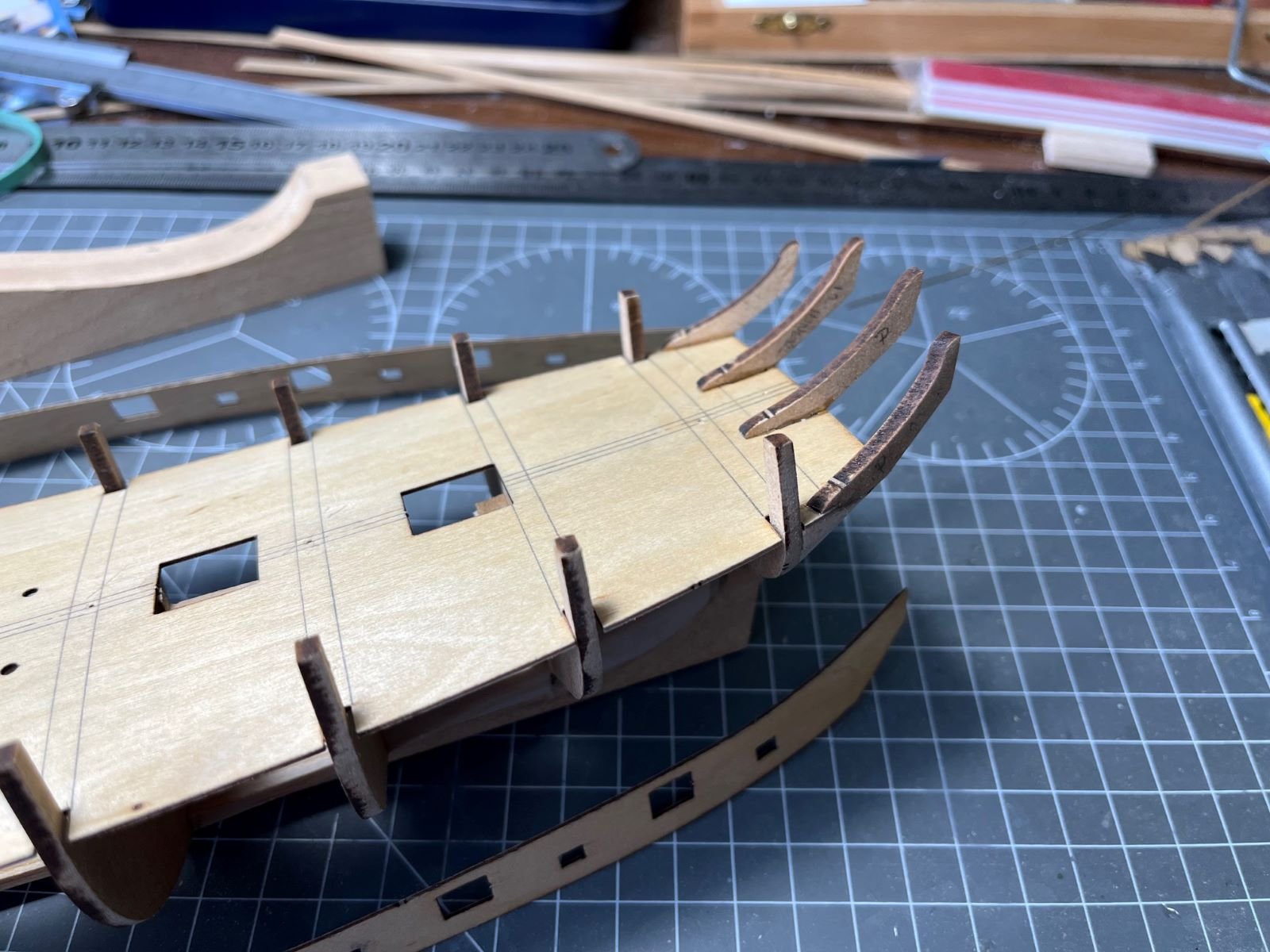
a little progress in building the hull of my model, approximately following the steps of the instructions of the kit. I glued on the four extensions that support the stern (stern counter frames). The two inner ones need to be aligned with the vertical (i.e. they are not perpendicular to the deck) while the external ones follow the local contour of the hull. Being mostly overhanging outboard, to improve their strength, I glued them with epoxy obtaining seemingly a strong joint.

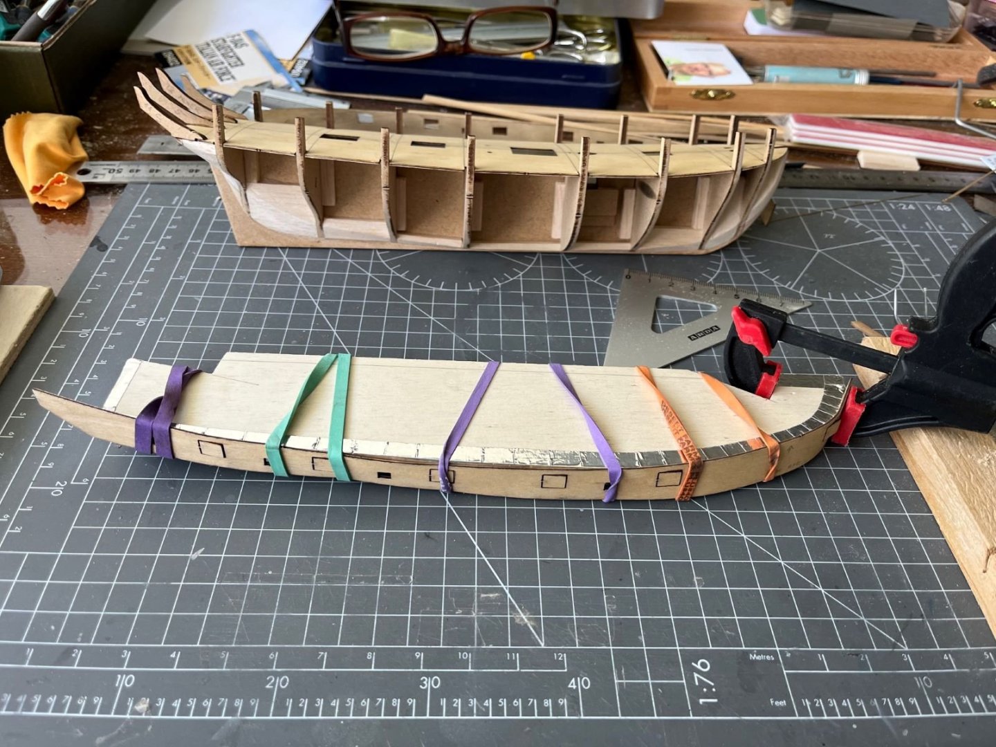
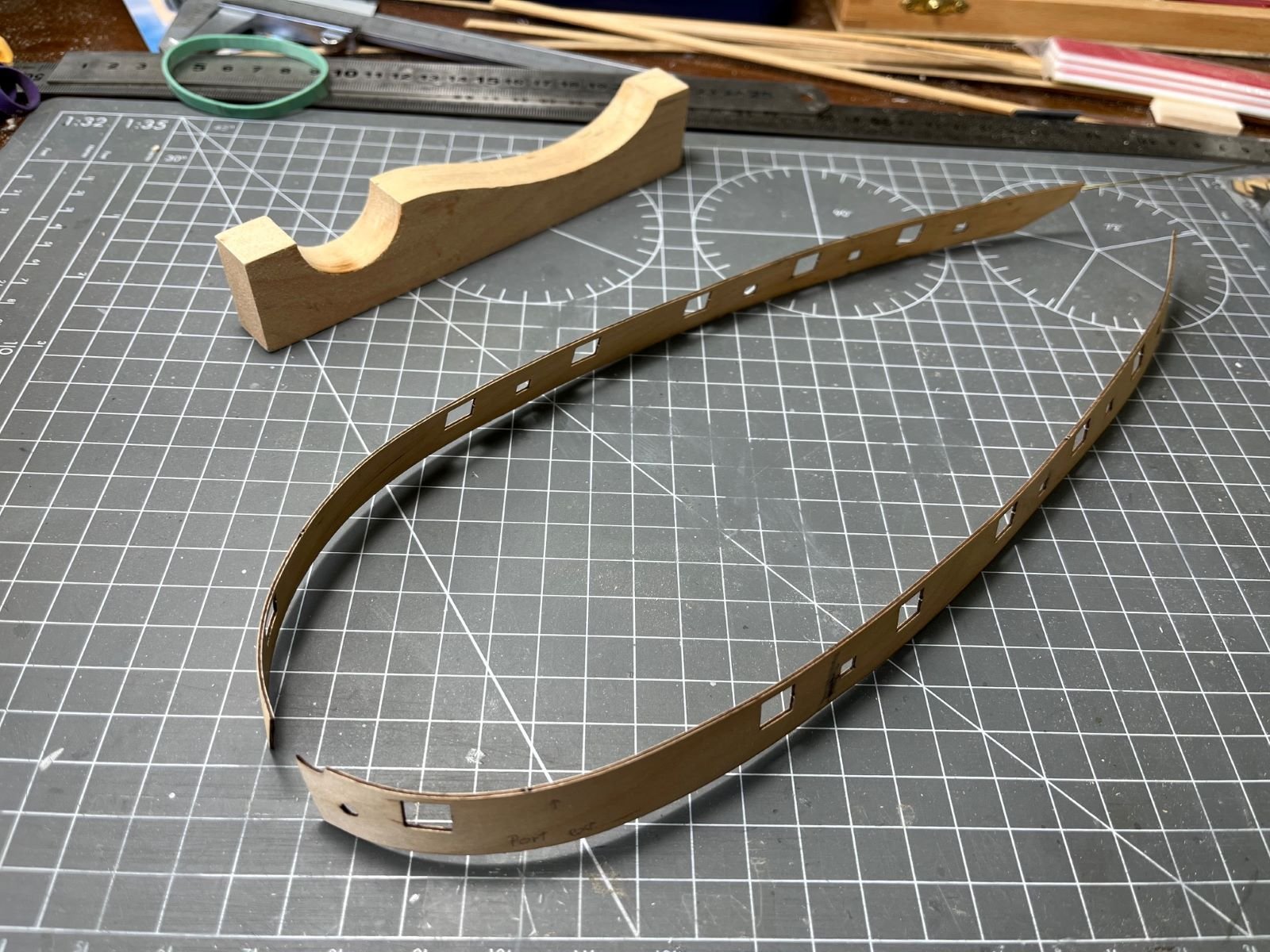
Then, I was required to bend in shape the bulwarks that are made of thin plywood 1 mm thick. To bend them in shape I soaked them in water and let them dry against a shaped plywood board as shown above. Once dried, I refined their curvature by an electric bender obtaining regular nicely curved parts which match quite well the deck and the exposed extensions of the frames.

Before gluing them on, I need to glue the walnut prow and keel, hoping that they will not get spoiled by the planking. Meanwhile, I boxed the receptacle for the foot of the mast to provide the mast with some lateral support.
That's all for now,
best regards,
Dan
- Gregory, allanyed and chris watton
-
 3
3
-
Hi all,
here I would like to start and share with you my new build of the wooden wonder De Havilland Mosquito 1:48 scale. The kit is the old, but still very nice Tamiya of the FB Mk VI (Fighter-Bomber).
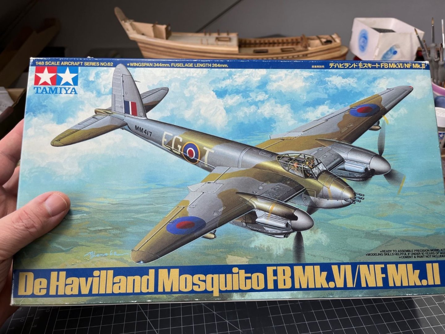
Since long time, I wanted to build a model of this aircraft because of its fame and because of its remarkable design. For me, this is the first Mosquito build as a grown up modeler if I exclude the ancient Revell 1/32 kit that I built when I was a kid.
To start my build, I followed to the letter the Tamiya instructions which called the engine nacelles as a first step:
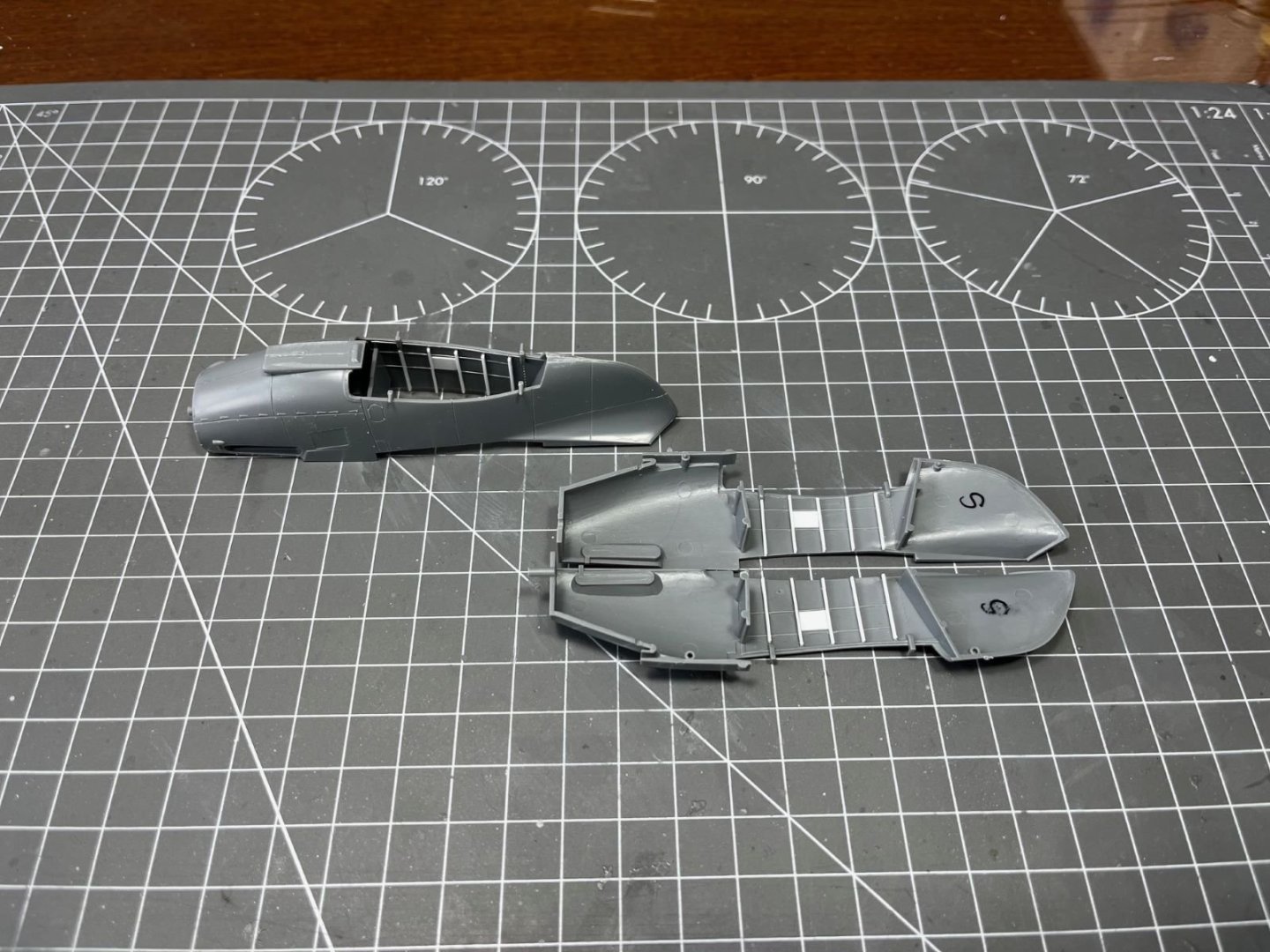
For added 3-D effects, I just thickened the frames of the nacelles and added few interior details. The white panel shown on the inside walls is an artistic license of mine having used a piece of thin styrene to hide annoying ejection pin marks which I didn't want to fill and sand. In the following, the nacelles are shown completed:
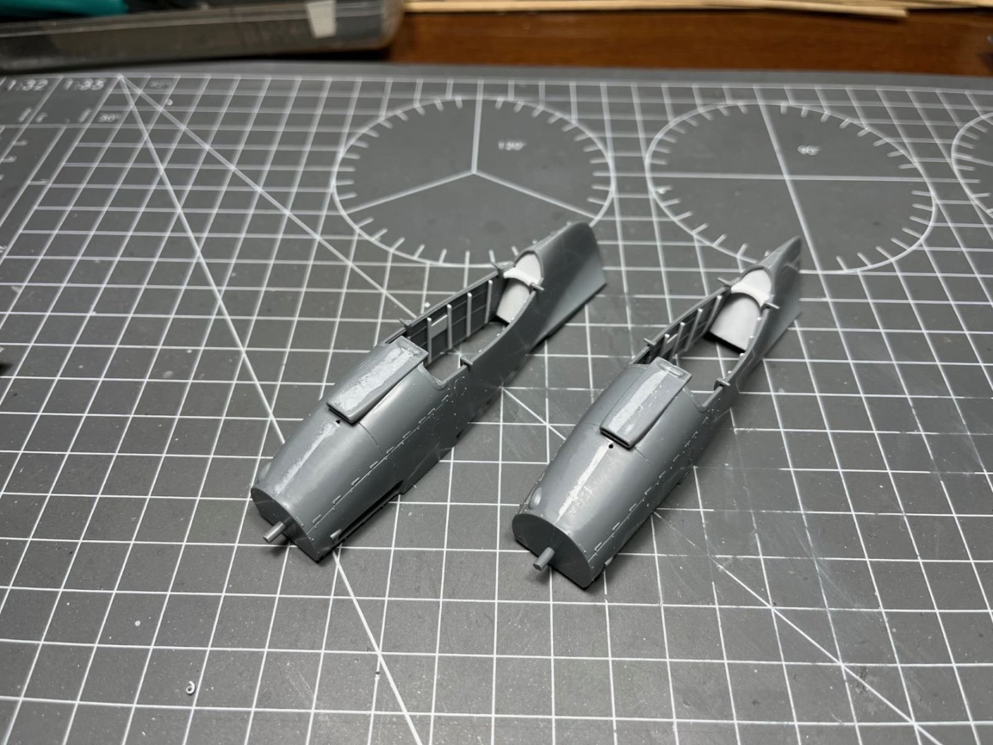
They are test fitted with the wings and with the main undercarriage struts to check that no interferences with the new added parts are present:

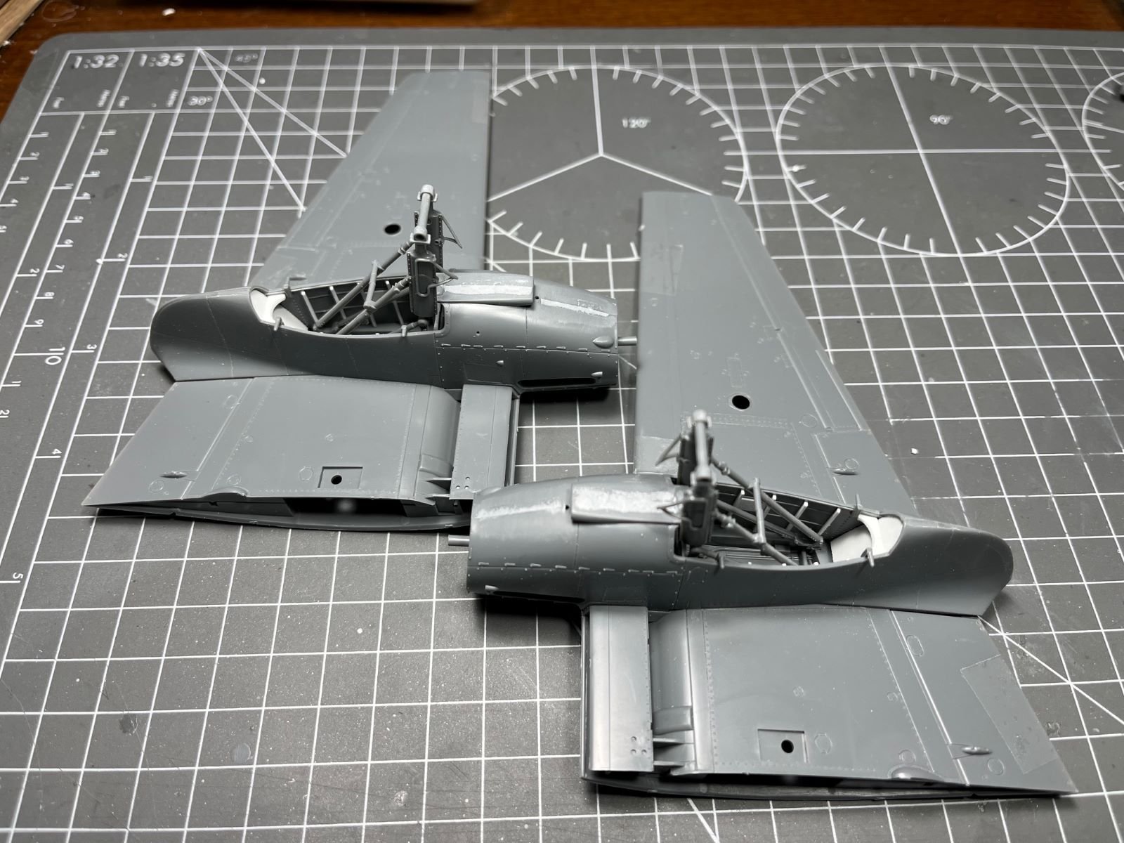
I was a bit puzzled by the way the main undercarriage is supposed to be assembled. If I follow the Tamiya steps, I am going to get the large wheels in the way when I will have to finish off and paint the truss structure. Actually, it is desirable to be able to install the wheels only after everything is assembled and painted. To resolve this issue, I removed altogether the molded plastic wheel axles and replaced them with a brass tube 1.6 mm dia. that can slid in and out as shown in the picture.
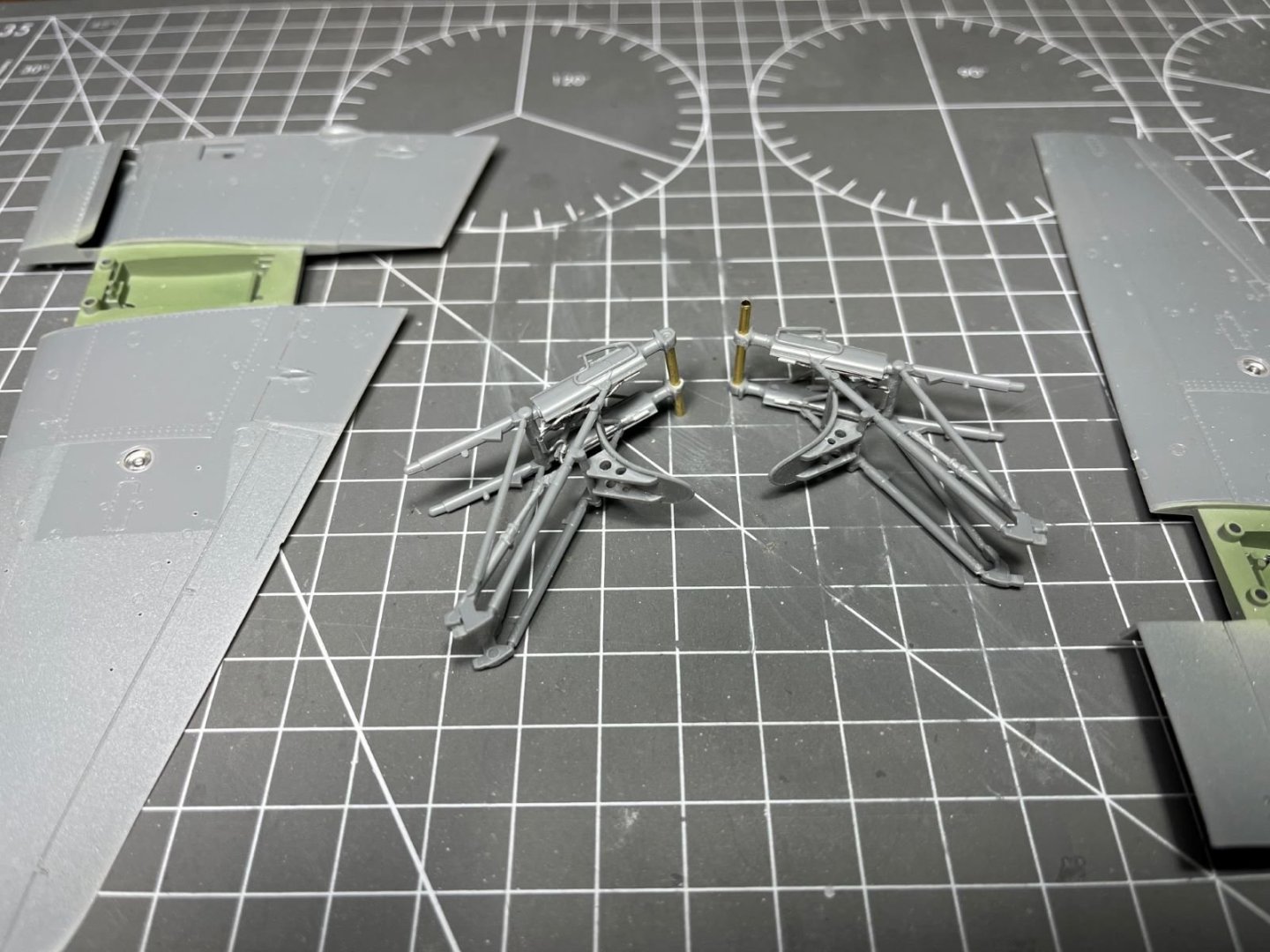
Once trimmed in length, the new axles could be slid in place to install the wheels at the most convenient moment. Without the wheels in the way, I could assemble and finish the undercarriage structure properly and fit the brake lines made of lead wires. I also drilled lightening holes in the supports of the mud fenders to add a little, but nice detail. Here the completed undercarriages are posed within their locations on the lower wing halves which have been painted interior green.
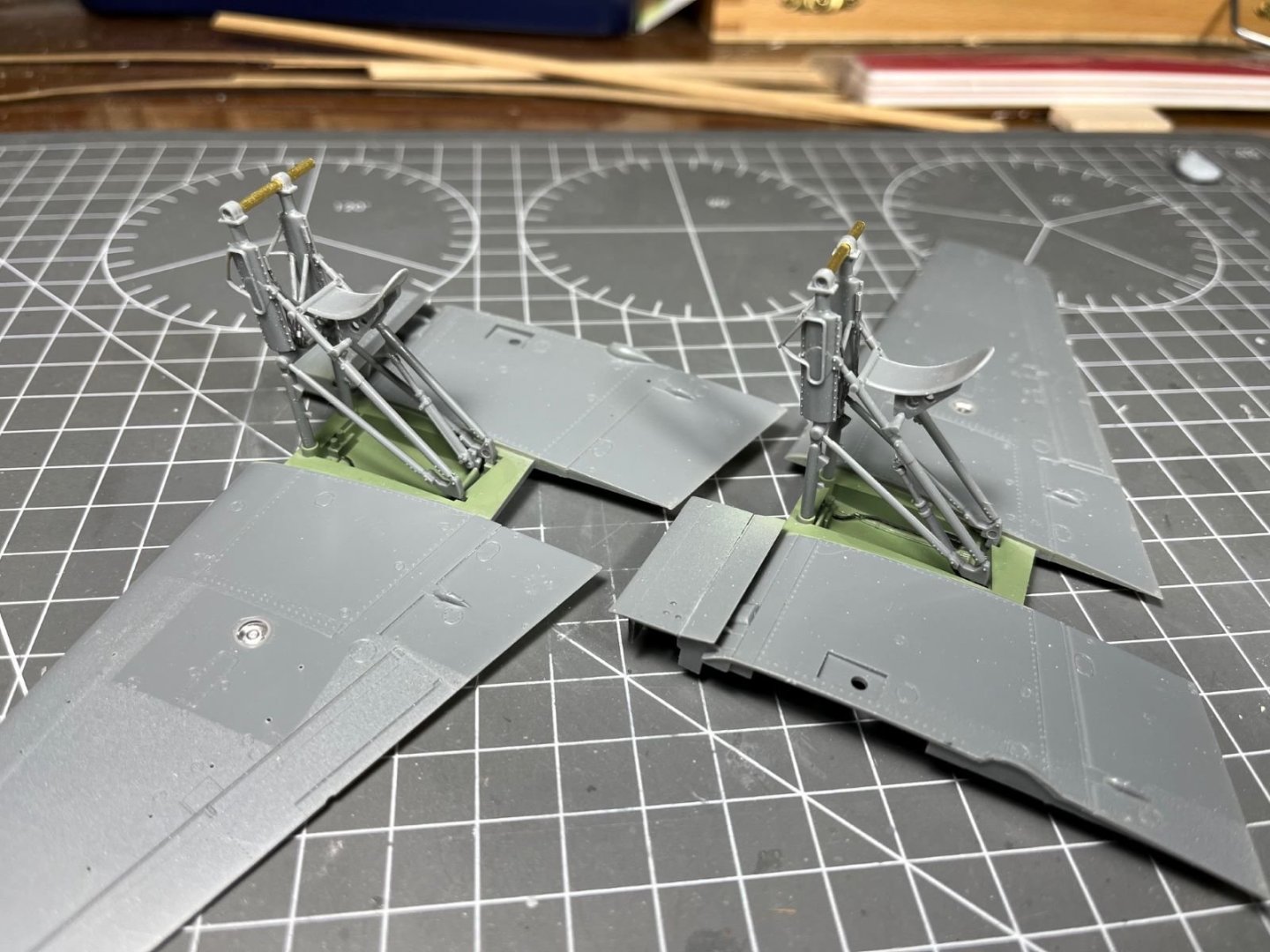
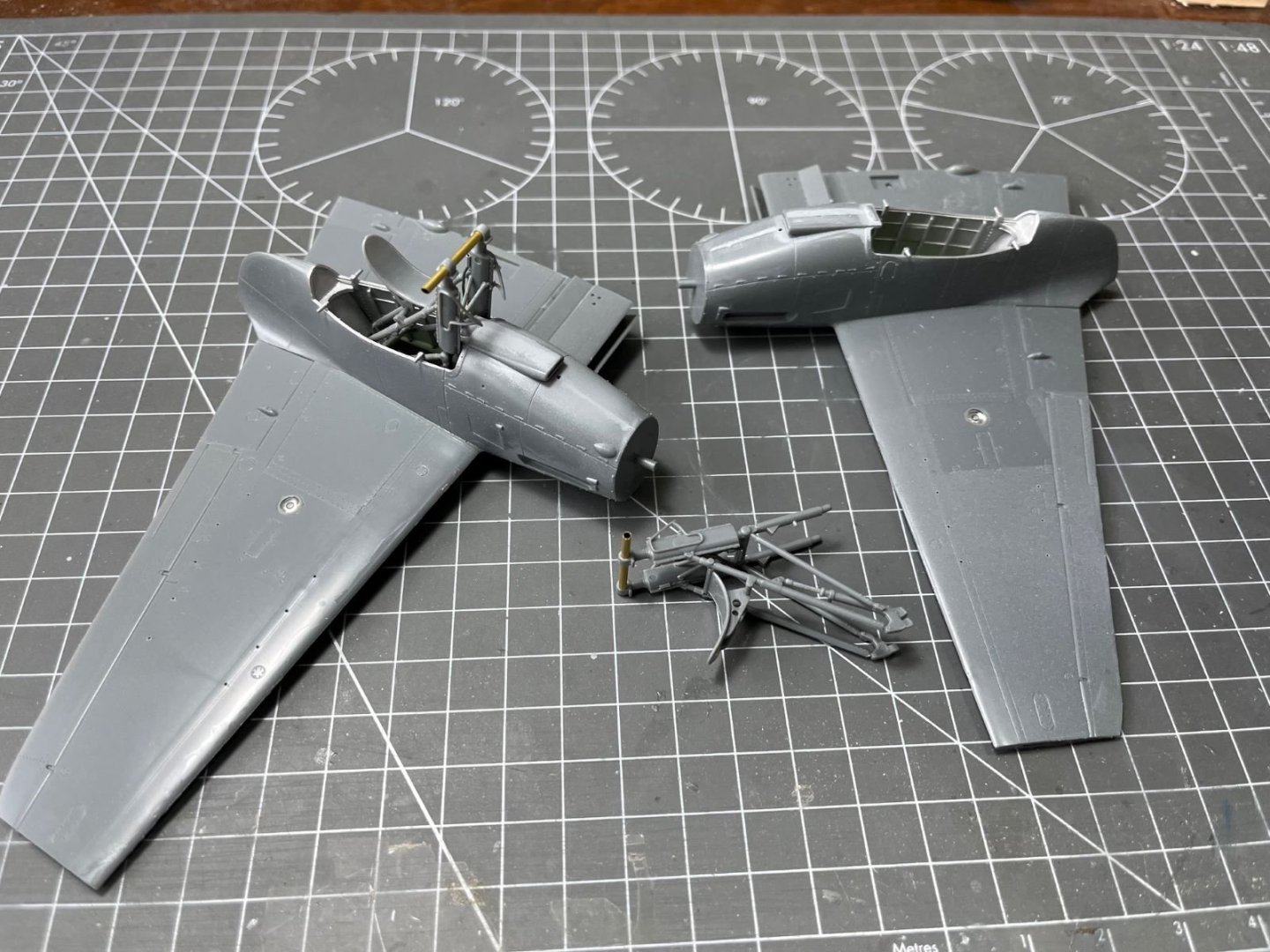
I read that to improve commonality of parts, the real undercarriages were not handed, but I left them as they are intended in the kit because their modification it would have been a complication for me. Finally, the nacelles were glued in place and the half wings were completed. The undercarriages are now ready to be painted.
Not much, but that's all for now, thanks for having you following,
best regards,
Dan
-
Hi Chris,
it is a rectractable step that was unblocked by operating the lid of the hand handle. Closing the lid, the step would retract by the action of springs. So, step down with hand lid open and vice versa.
Dan
- Canute, realworkingsailor, Egilman and 4 others
-
7
-
Dear all,
I am starting a new model and I would like to share it here to get advices and comments. I momentarily put on hold my previous long standing model of the Mayflower by A.L. because I got a bit tired of it and I wanted to start a smaller model that I could build and progress quicker with and I chose the ‘Lady Nelson’ by Amati for that. I noticed that this is quite a popular model and I could find many several WIPs of this model here. Indeed, this is small a model and it should be rather quick to build.
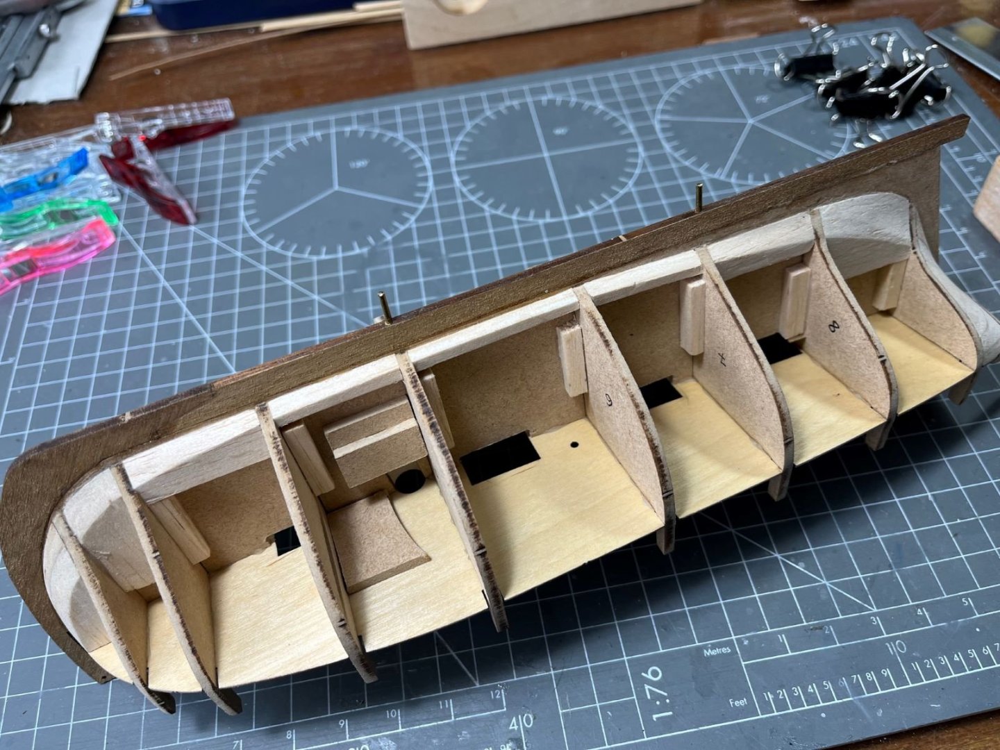
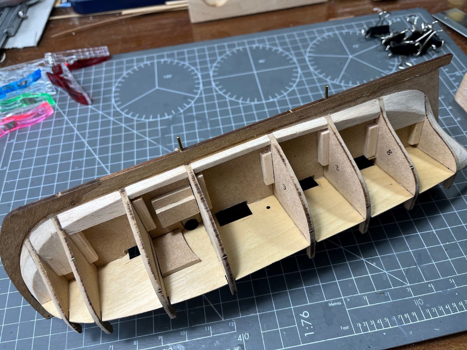
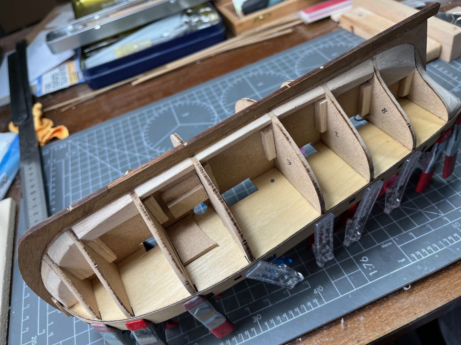
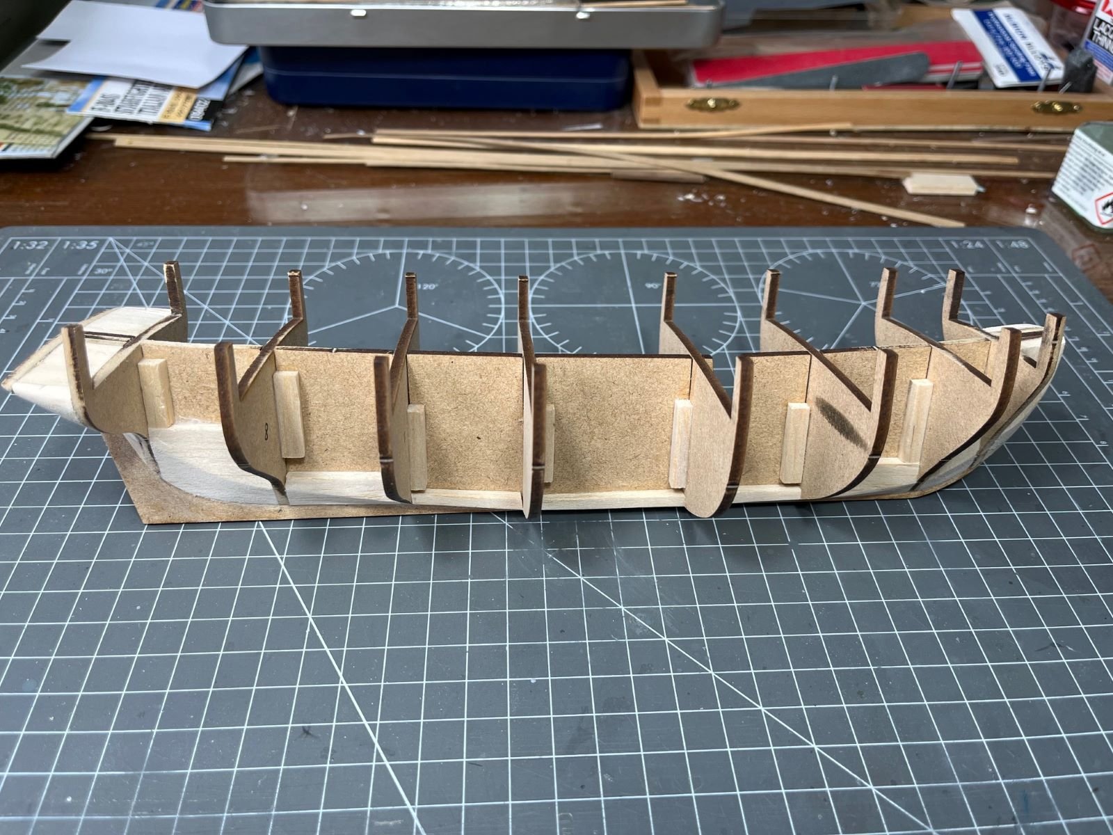
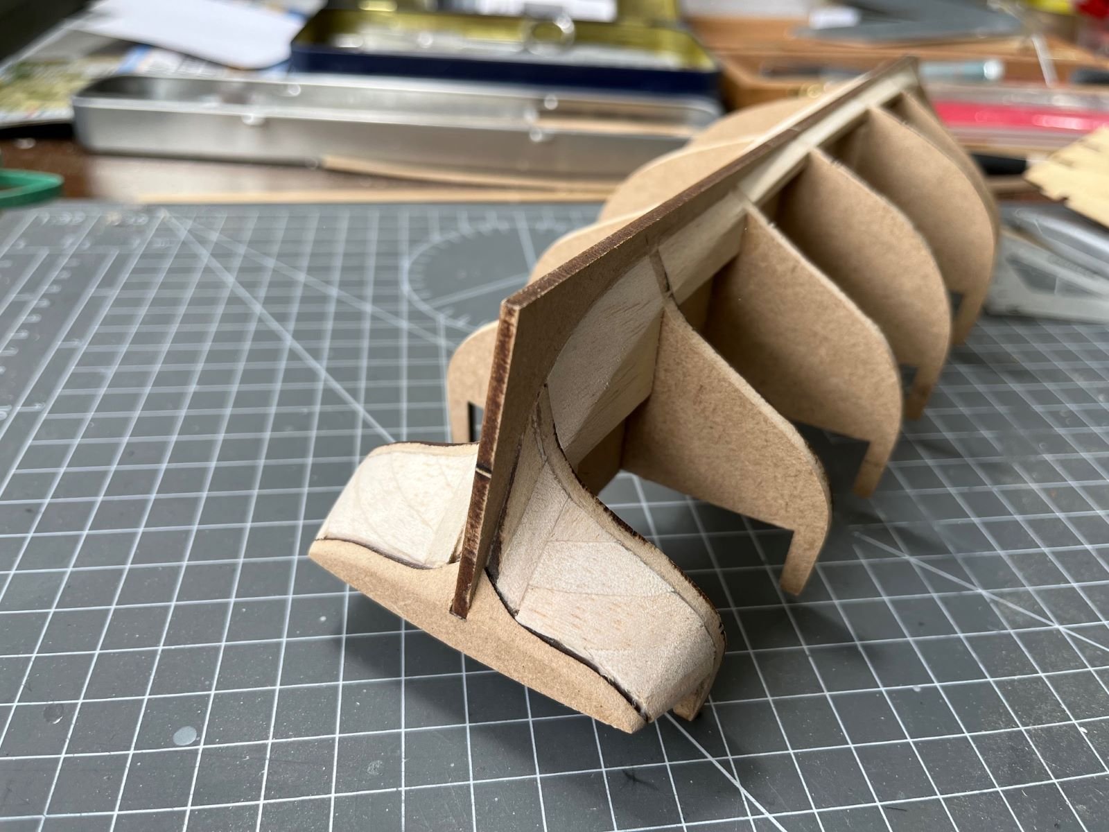
The kit is quite well known and documented here, so I am not reporting any unboxing picture. The initial assembling of the hull structure is relatively obvious, so I proceeded without taking pictures and I am directly posting some pictures of the assembled keel with the bulkheads.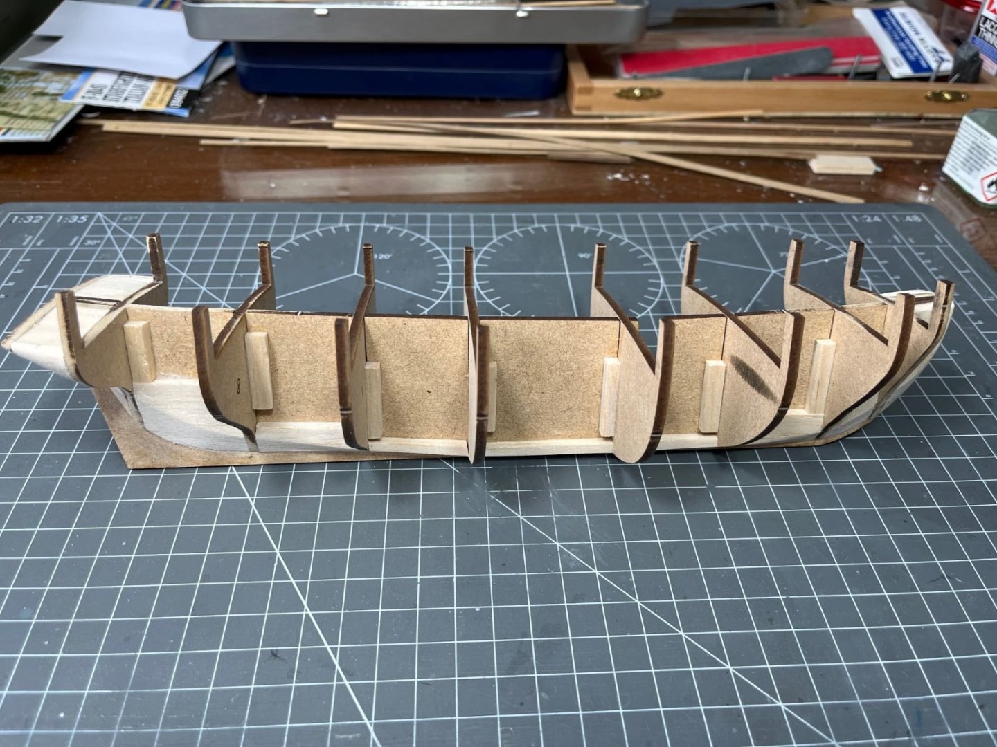
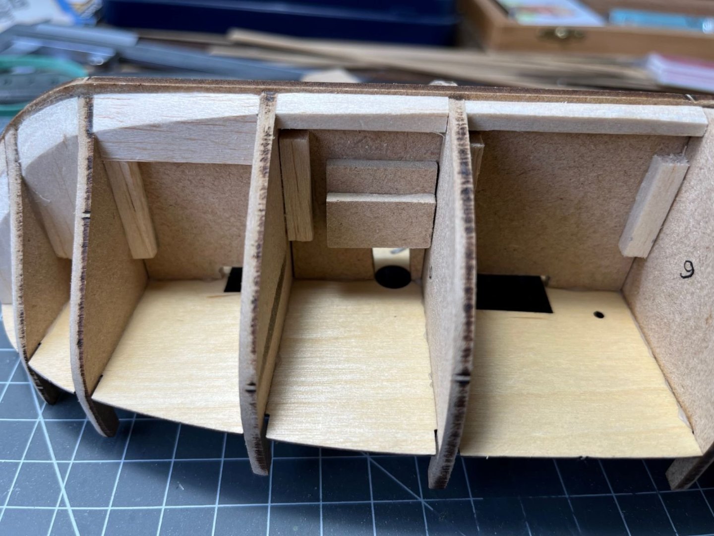
As others have noted, the various parts have a loose fit, hence I added balsa square strips to locate them better and provide some support. In addition, I added balsa gussets in addition to the MDF parts supplied by the kit to support the strakes at the bow and along the keel where the garboard will sit. I did that also in my previous build and it worked quite well.
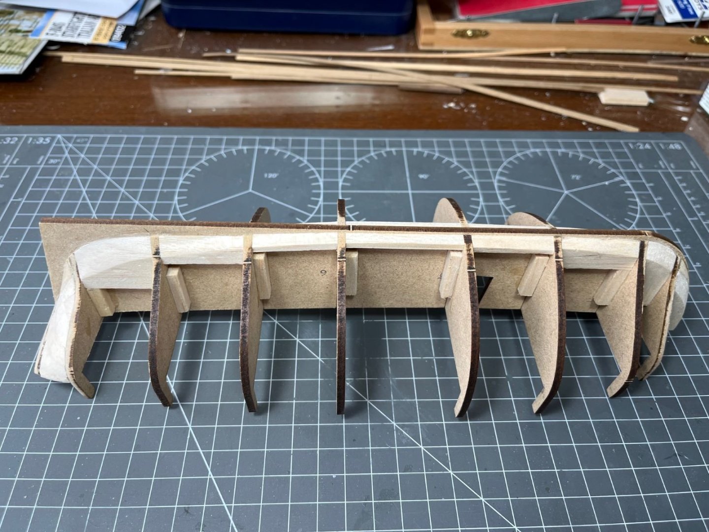
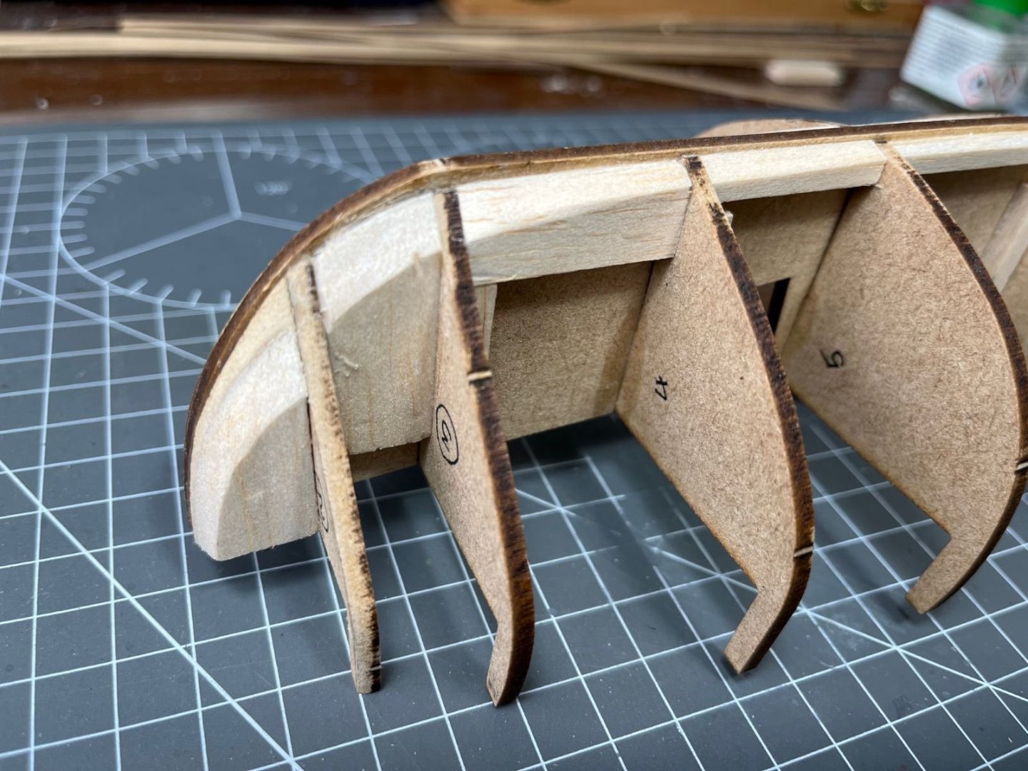
I also filled with balsa the last bay at the stern. I used balsa plates 5 mm thick for that because when filed they provide sort of ‘waterlines’ that might be used as reference to check the shape and the symmetry during the sanding process. At the stern, after some sanding, I ended up with this configuration where the last frame was mostly filed down and its fillets were mostly removed when I tried to fair it with the rest of the hull. It seems that other modelers have left some of the fillets instead.

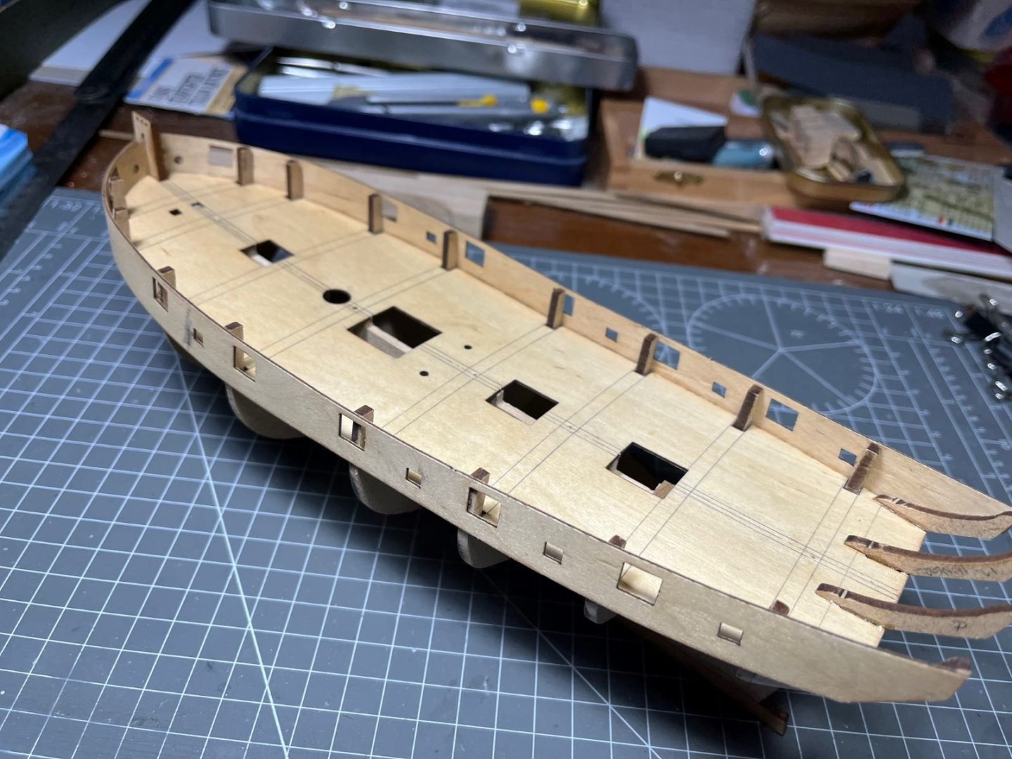
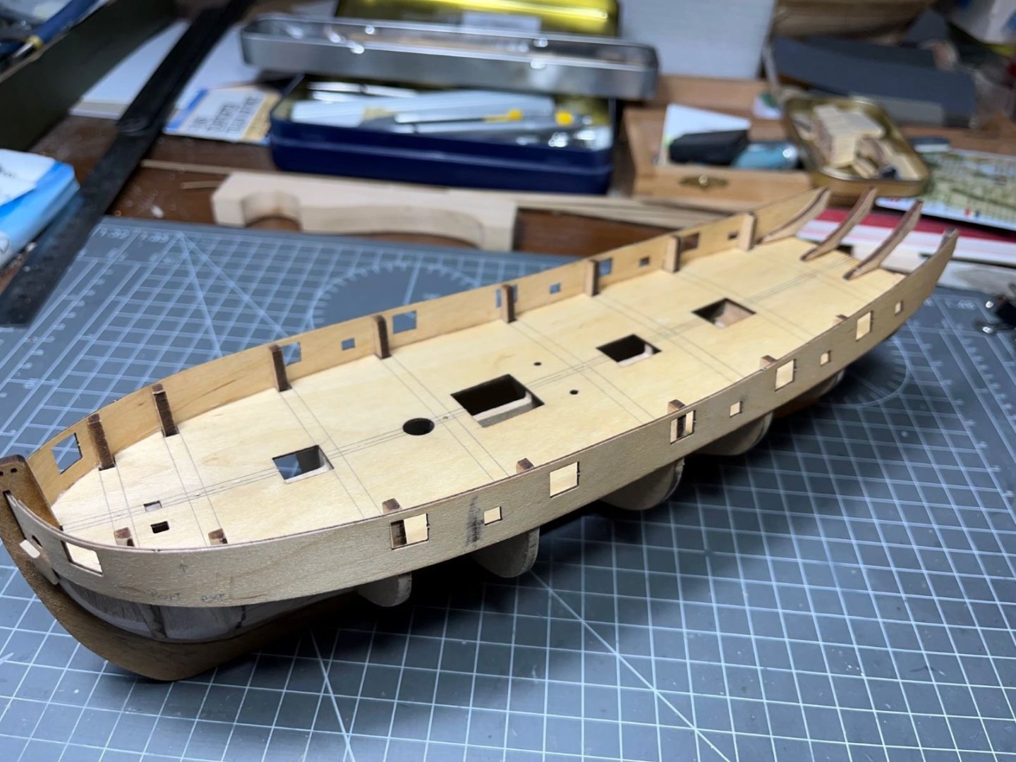
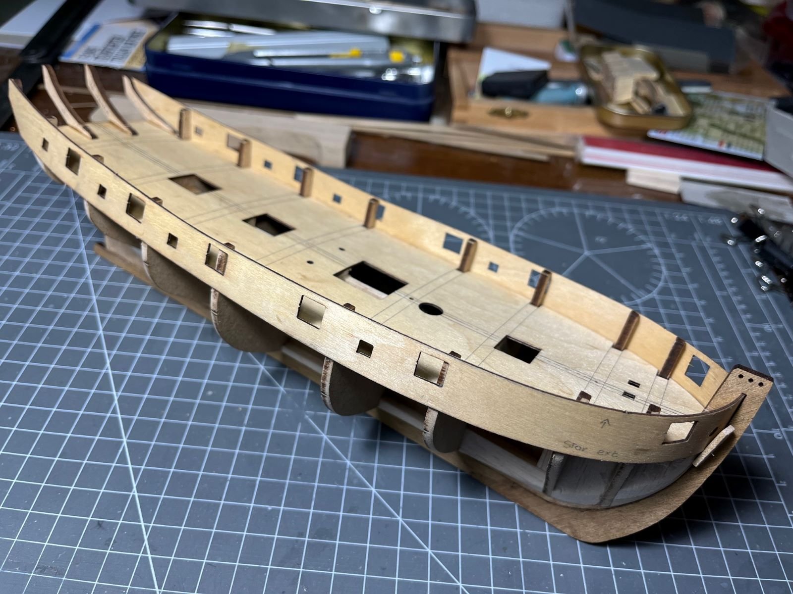
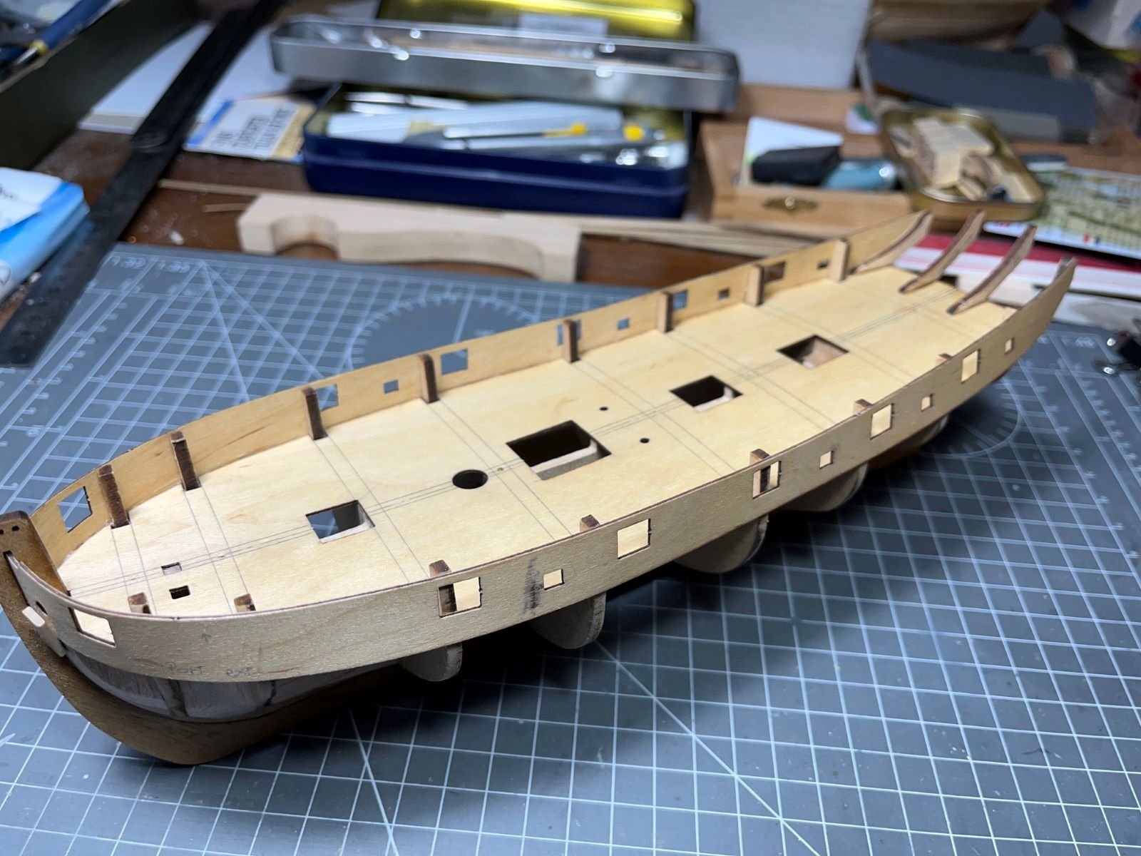
This is the complete hull after that most of fairing job was done. At this point, before finalizing the fairing, the instructions call for attaching the false deck.
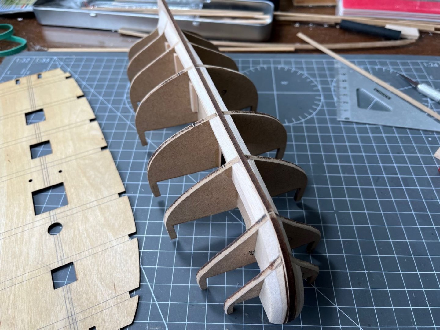
This part is made of very thin plywood and it complied with the double curved shape without problems. Finally, this is the hull completed with its false deck.
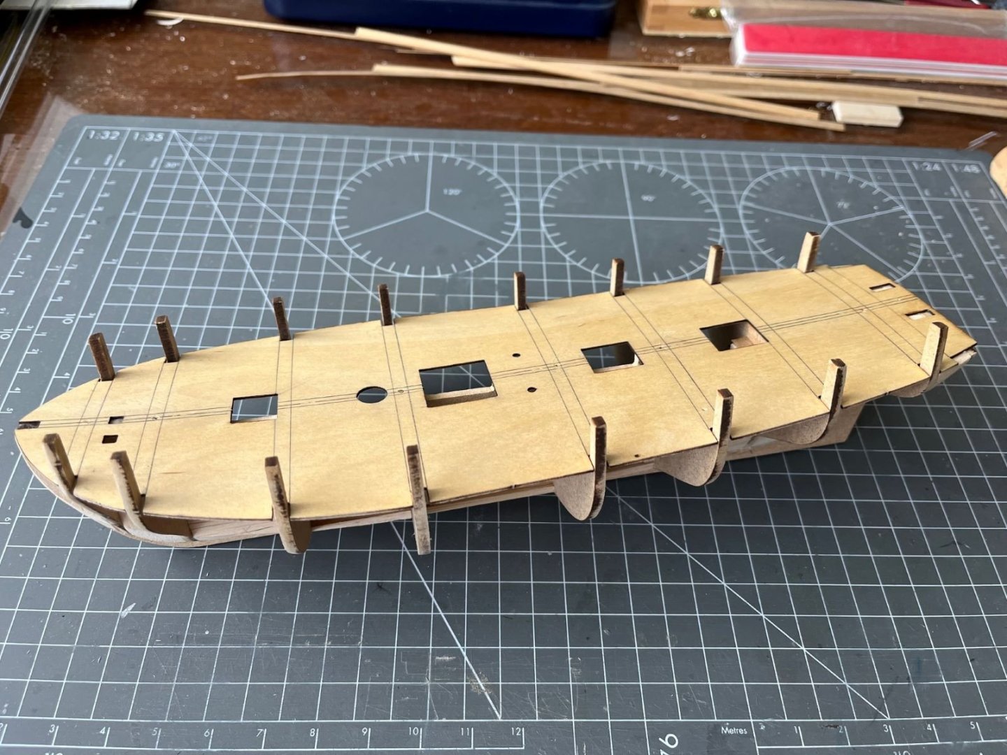
Just to create a bit of a recess in correspondence of the deck hatches, I cut shallow notches into the false keel piece. Next, according to the instructions, the bulwarks pieces need to be formed and glued in place together with the keel extensions. In connection with that, I note that the instructions do not mention any need for implementing a rabbet and the details of how the strakes and the garboard strake join the keel are quite obscure.
That is all for now,best regards,
Dan
- Gaffrig, Knocklouder, Thukydides and 4 others
-
6
-
 1
1
-
12 hours ago, Landlubber Mike said:
Dan, somehow I missed that you completed this one. Another stellar build! Well done!
Thanks for your assessment, Mike. I am glad that you like it.
I am thinking to the next build which will be a De Havilland Mosquito.
Cheers,
Dan
-
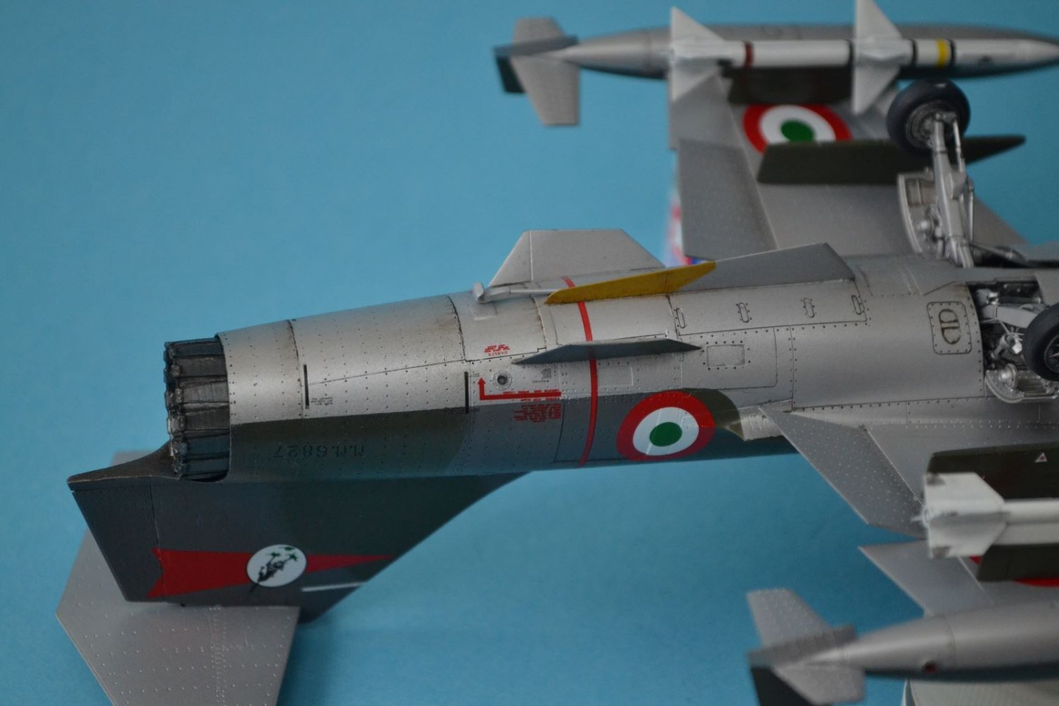
On 4/1/2024 at 6:18 PM, CDW said:
Can someone here please explain why this particular aircraft has those distinctive color striations at/near the afterburner? I've often wondered but never read an explanation of why they all seem to have this look.
This can happen when Titanium alloy is cladded with aluminum. In my working experience, testing a titanium foil with aluminum deposited on it at high temperature (around 450 C) we got such a discoloration. The phenomenon is due to the aluminum getting migrated into the titanium and forming a intermetallic compound that had such a discoloration. A more familiar but similar phenomenon was visible with exhaust tubes of old style motorbikes that had tubes made of steel coated with chrome. Also in this case, under the effect of high temperature, the chromium went dissolved into steel making the typical, and much nicer in this case, bluish discoloration.
I hope this help,
Dan
-
-
-
-
@ccoyle, @Canute, @king derelict, thank you so much for your kind feedback which I truly appreciate.
Thanks also to the various 'like's.
To the next build,
Dan
- Jack12477, Old Collingwood, mtaylor and 4 others
-
7
-
On 3/15/2024 at 3:04 AM, ccoyle said:
The patch has been made (it's ugly), the aft fuselage completed, and the vertical stabilizer added.
It is anyway a good save! No kit left behind.
Dan
-
7 hours ago, Egilman said:
Do me a favor, show us a modern model where the modeler filled and sanded the wing to get that color effect.... I've been unable to find one....
One example might be in the following video:
Said that, I should have puttied the wings of my Starfighter, but for laziness I didn't 😂
@CDW, sorry for having highjacked your post.
Cheers,
Dan
-
6 hours ago, Egilman said:
But it is something impossible to model...
Sorry, I don't intend to contradict you, but I cannot see your point. Just fill the engraved details and then paint the wing with a paint that mimic the original one as, for example, shown in the following article:
Best regards,
Dan
- CDW, Old Collingwood, Dave_E and 3 others
-
6
-
22 minutes ago, CDW said:
Modern restored P-51’s show no evidence of the putty so I won’t try to model it now.
It is perfectly fine if you leave it as is. It will be a nice model anyway.
However, as far as references, for your next build, you might find plenty on the web. Just an example:
http://www.aviation-history.com/north-american/p51.html
Cheers,
Dan
-
16 hours ago, AJohnson said:
weren’t some Mustangs wings painted, even the NM ones?
Yes, even the metallic ones had the wing surfaces puttied and painted with aluminum paint (with the exception of removable panels). This was intended to get the maximum advantage from the newly introduced laminar wing sections. I don't know whether you might want to implement that at this stage.
Very nice finish and I love the blue nose with its glossy finish.
Cheers,
Dan
-
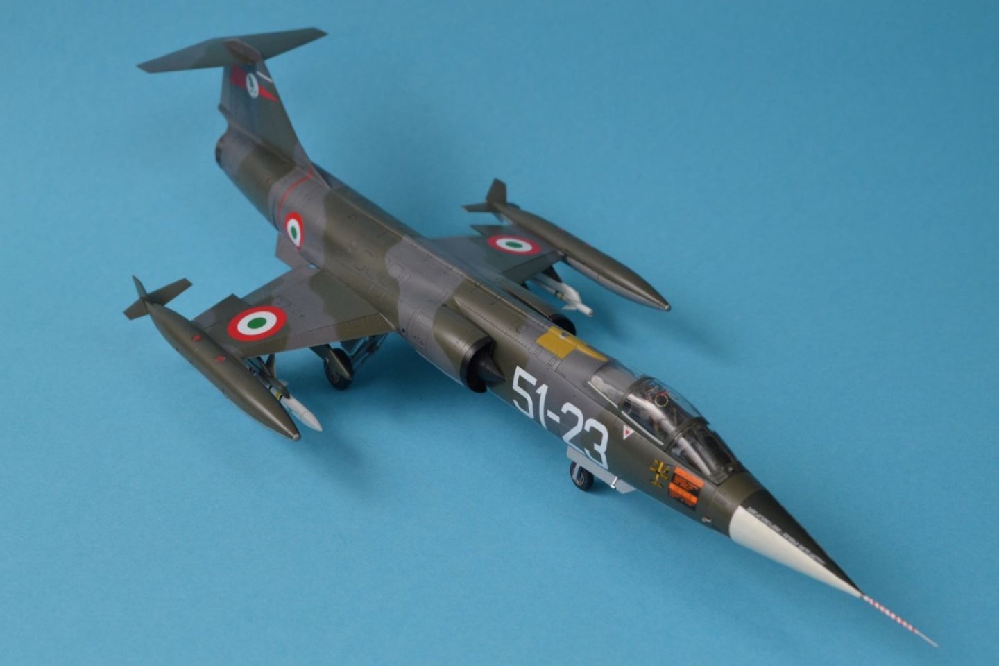
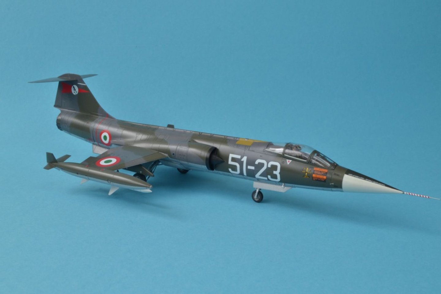
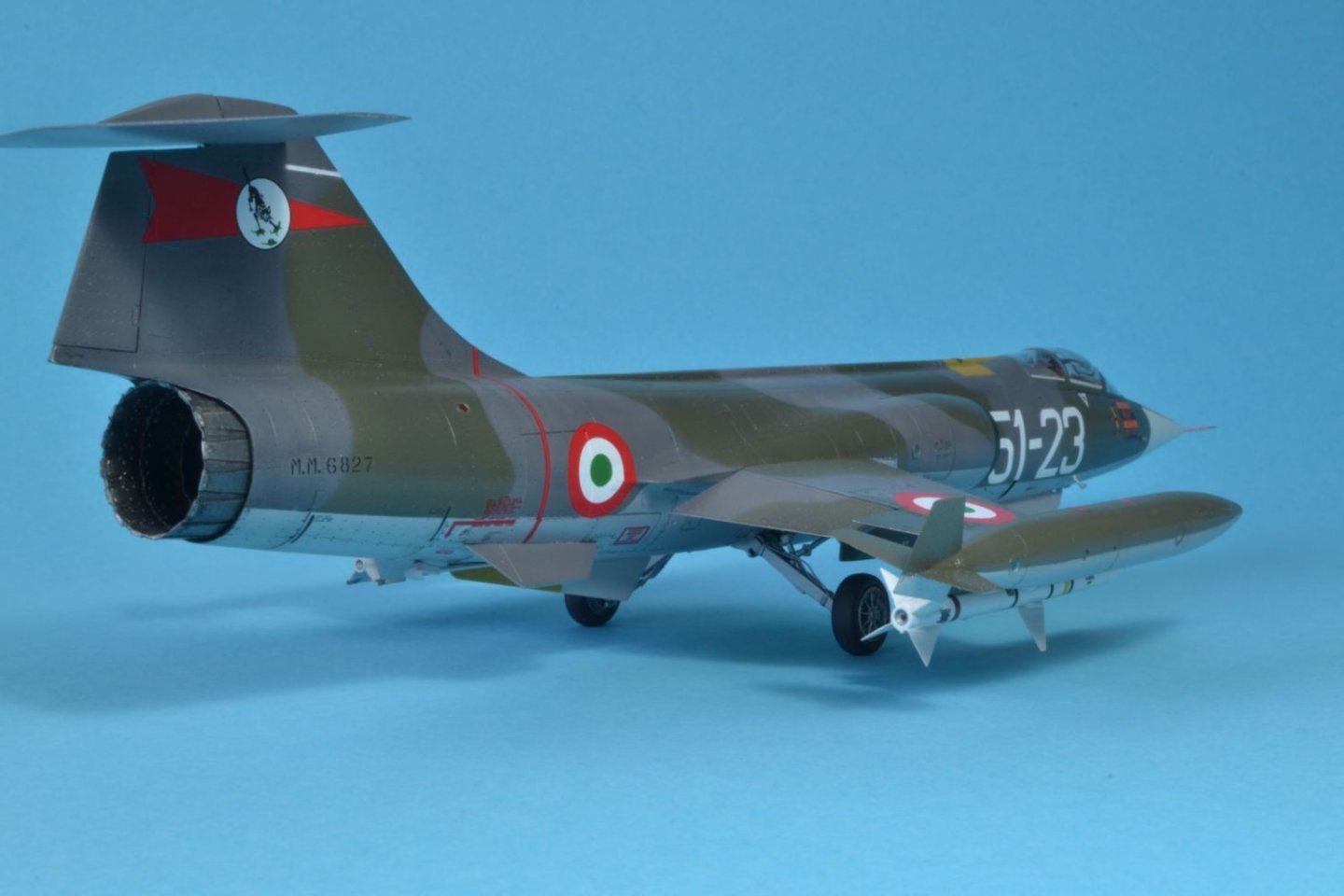
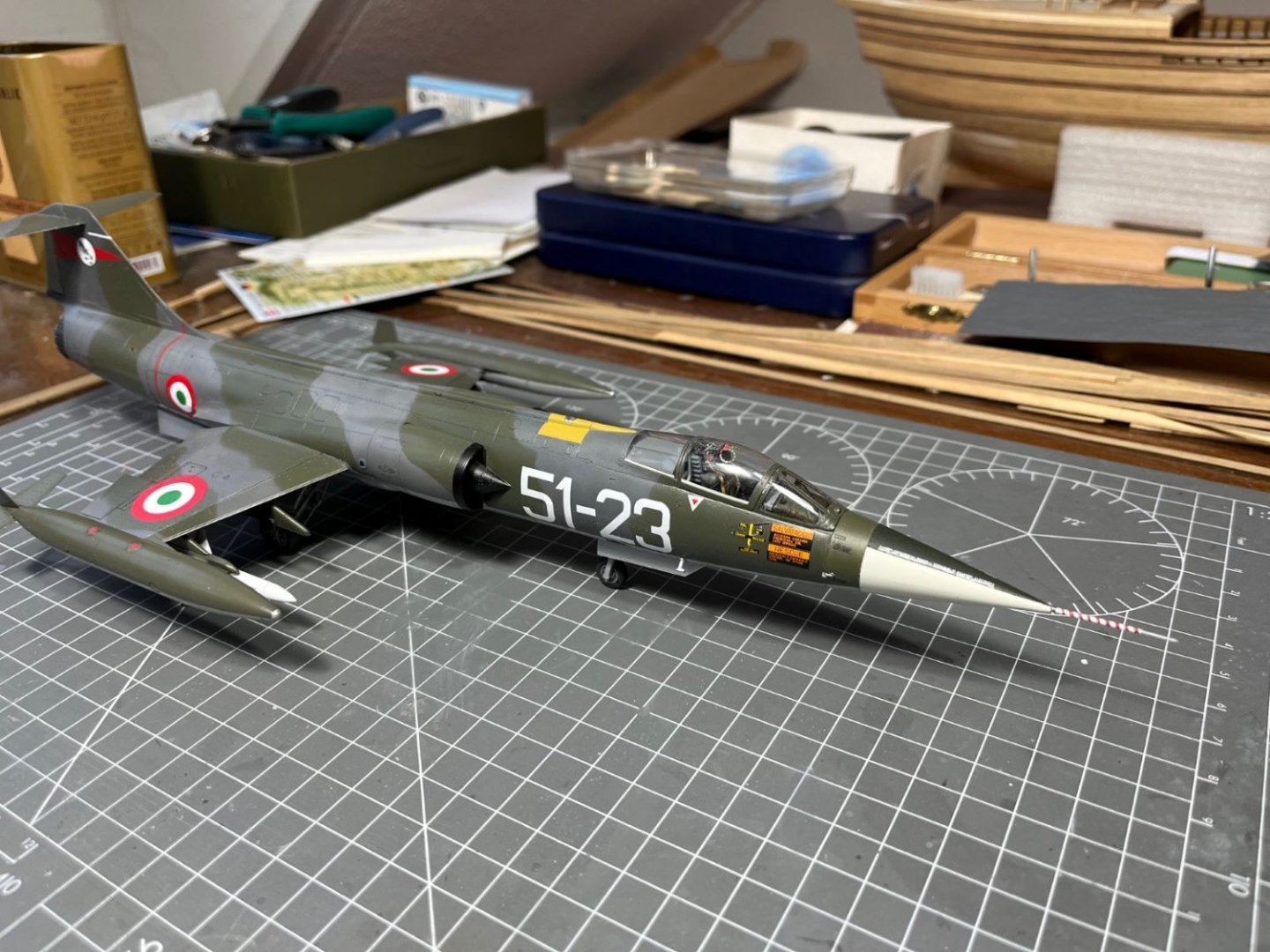
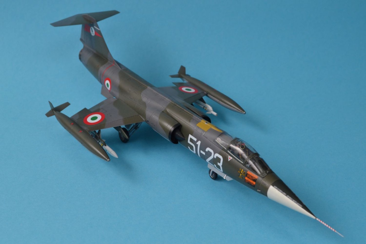
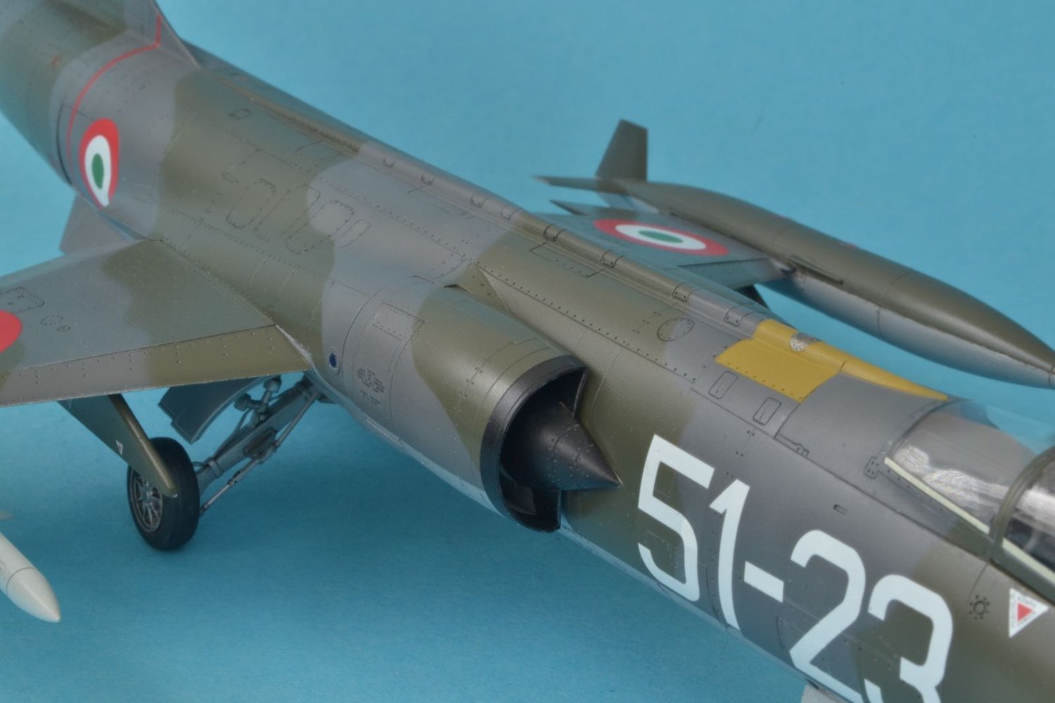
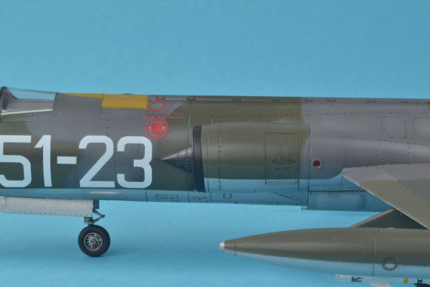
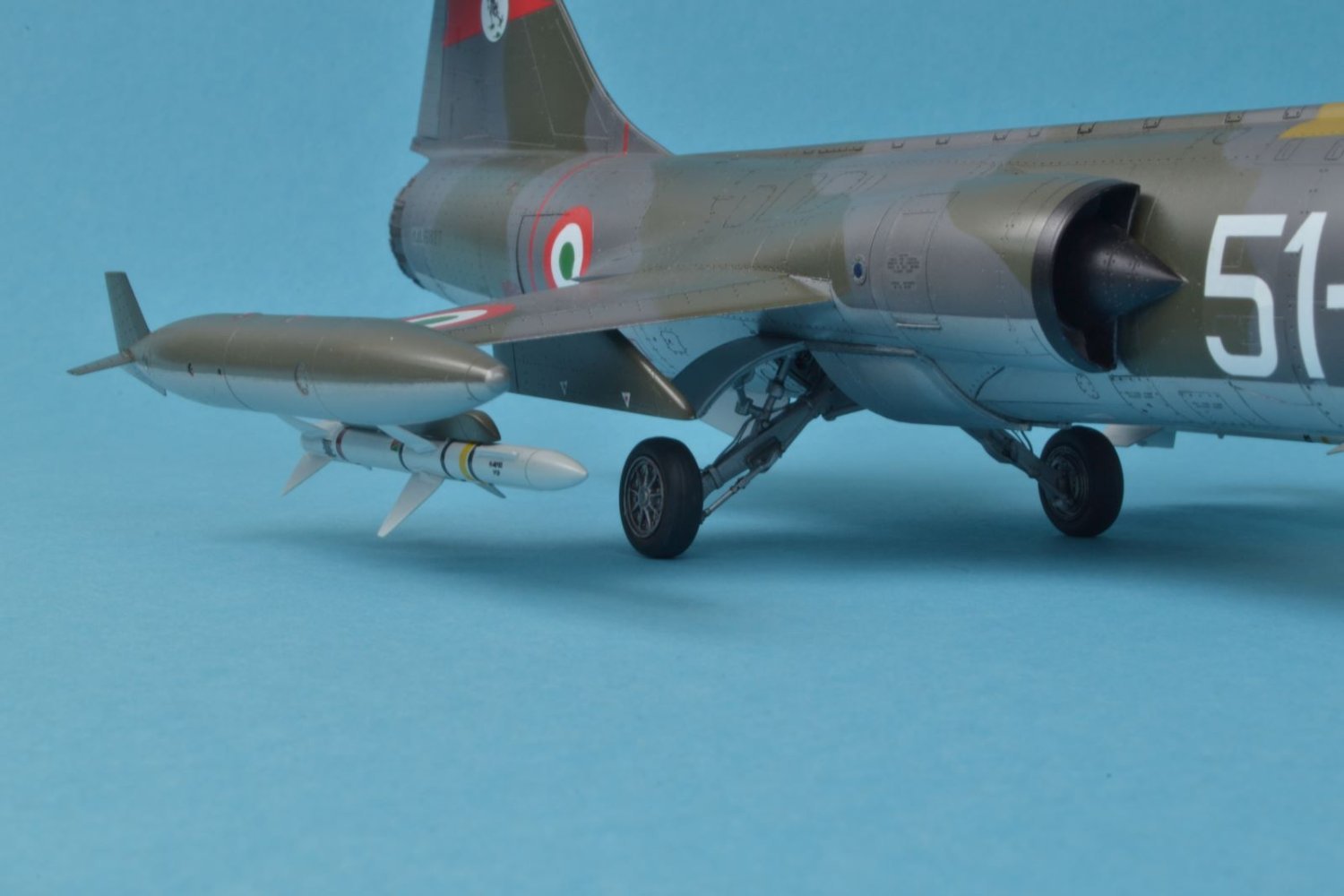
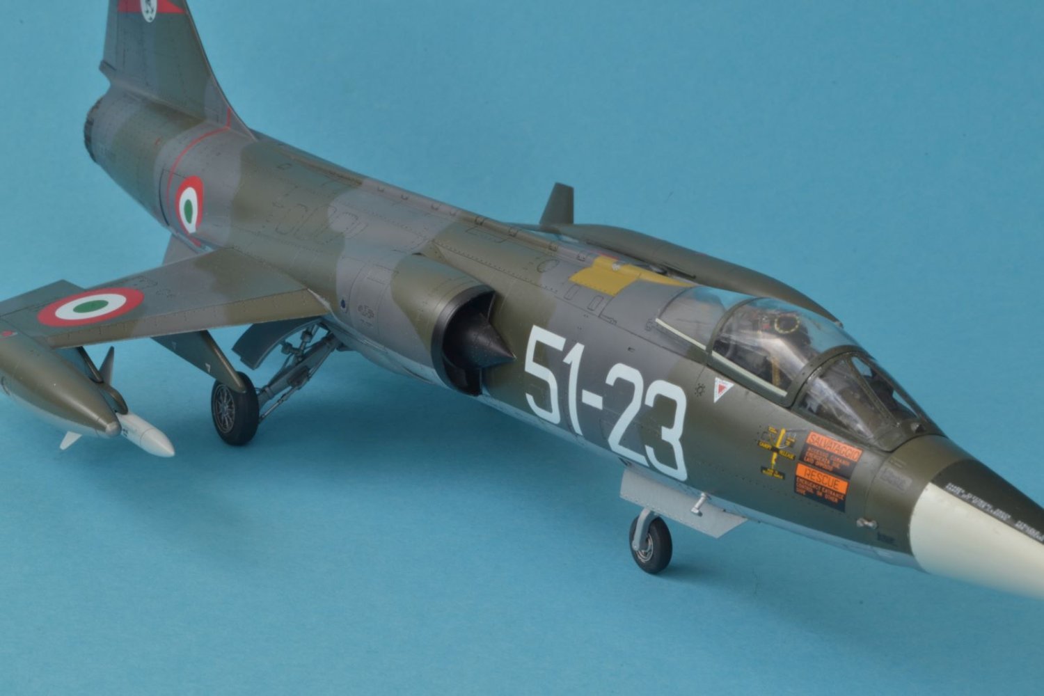
LOCKHEED F-104 S STARFIGHTER
Kit Hasegawa 1:48 scale
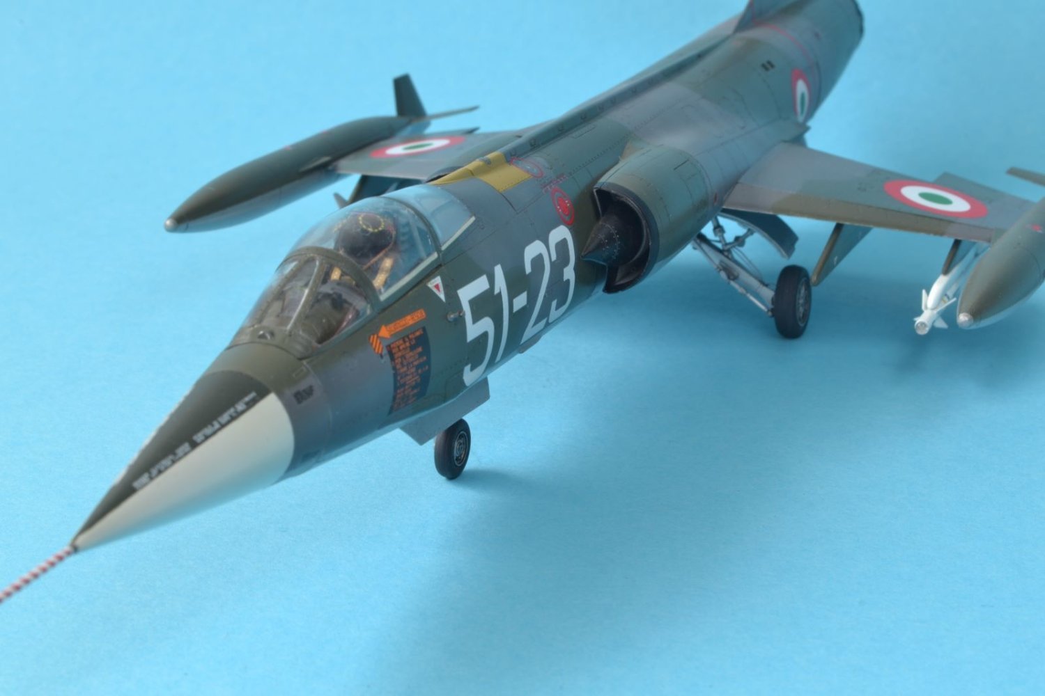
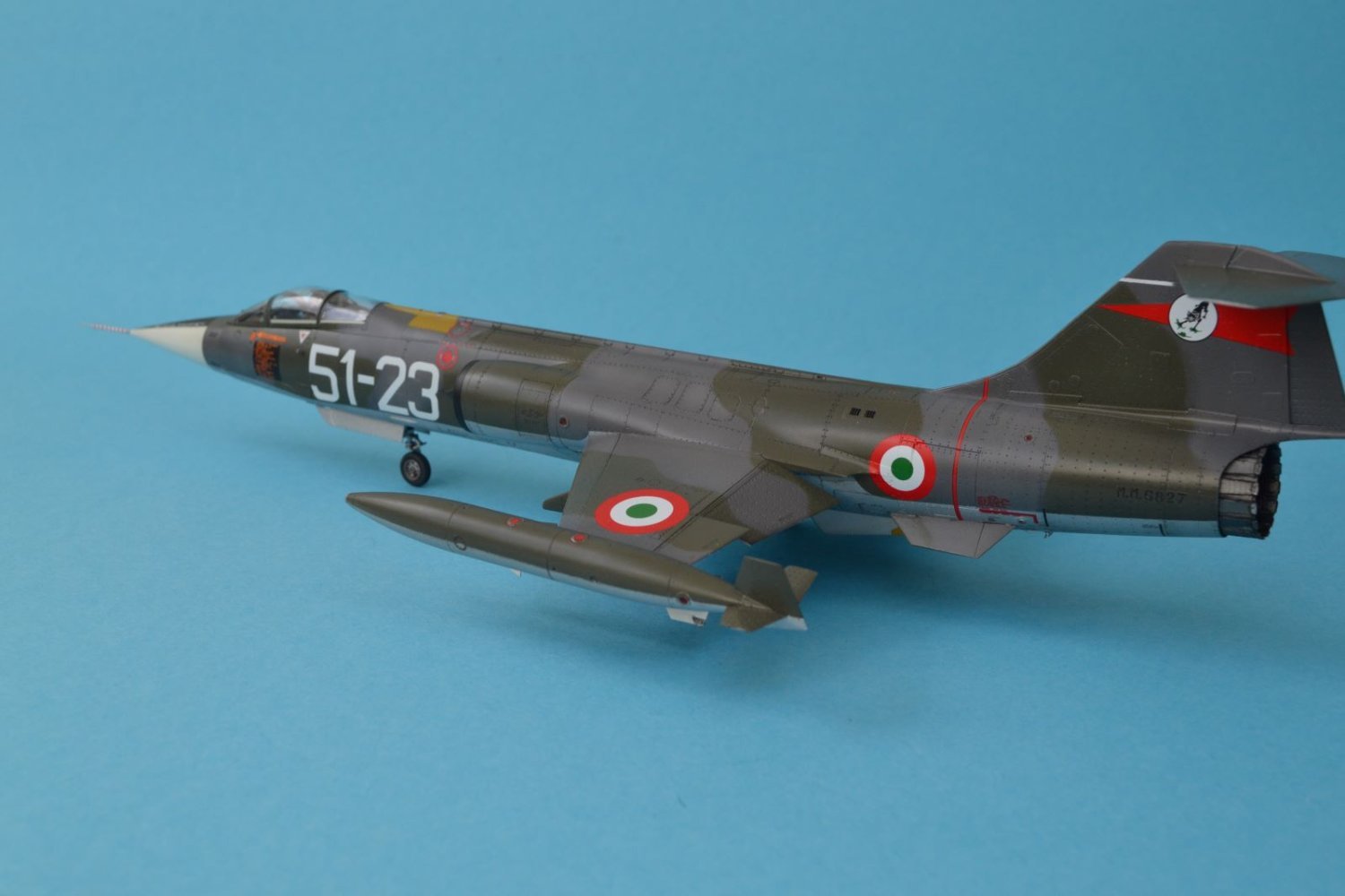
These are some of the final pictures of my finished model which depicts a Starfighter in Italian service.
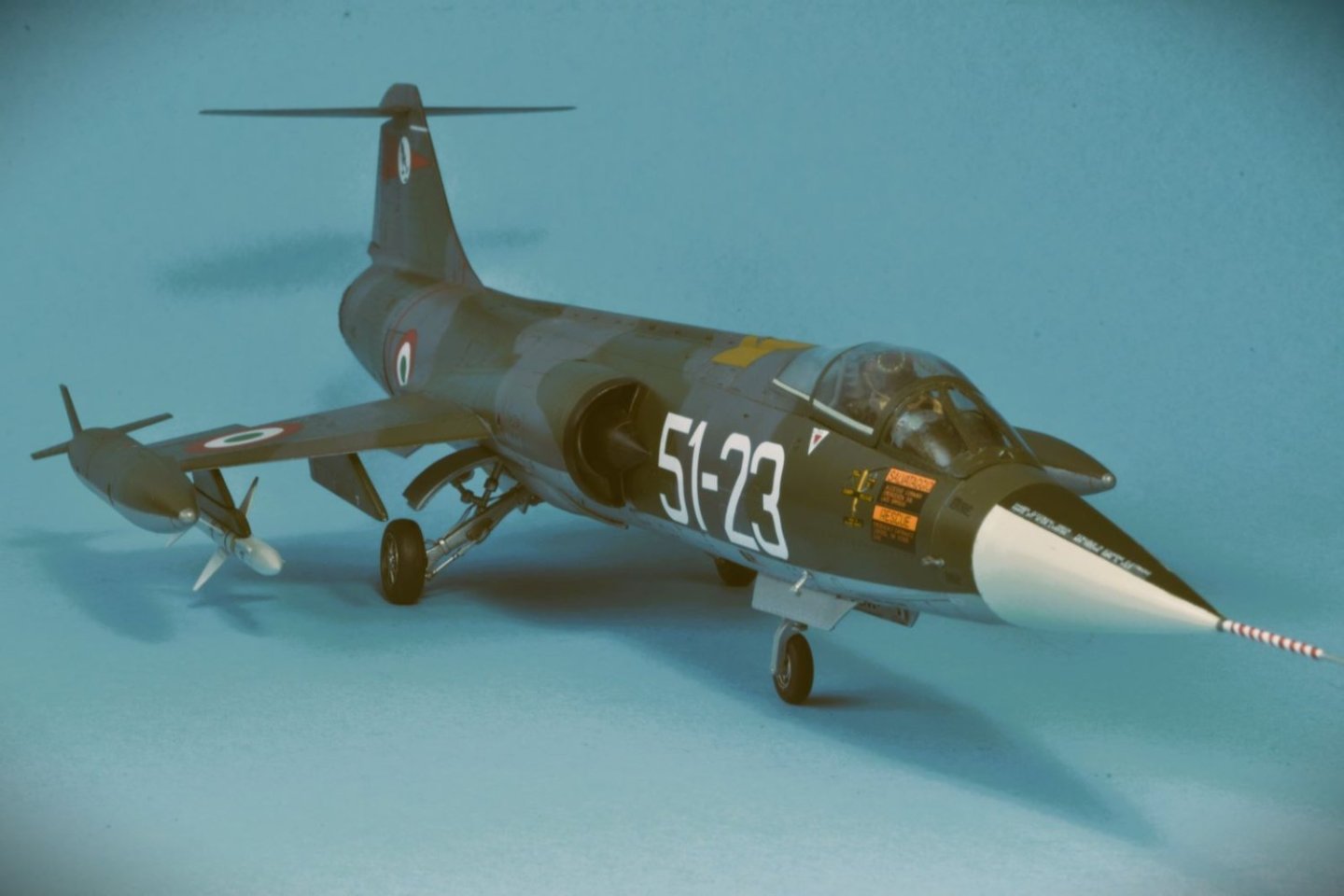 My F-104 carries the insignias of one of the interceptors of the 51st Stormo, based at Istrana, North of Italy as it appeared in 1981. This version started to be built by Aeritalia in Turin (former FIAT) in the late '60. It was powered by a more powerful J79-GE-19 and was armed with the version B or L of the Sidewinder missiles and with Sparrow missiles (from which the letter 'S' in the designation).
The kit is the old 1:48 Hasegawa of the F-104 S which is by now outdated by the newer 'state-of-the-art' Kinetic one. Nevertheless, I found that the plastic is still very nice with crisp and finely engraved surface details, thin and clear transparent parts and it well reproduces the distinctive forms of this aircraft. The build log can be found in the previous pages.


To improve the model, I sourced the following after market items:
- Aires resin jet exhaust;
- Master brass pitot probe;
- Eduard resin ejection seat MB Mk7 and harness;
- Eduard resin Sidewinder;
- Aires resin Sparrow;
- Skymodels decals.
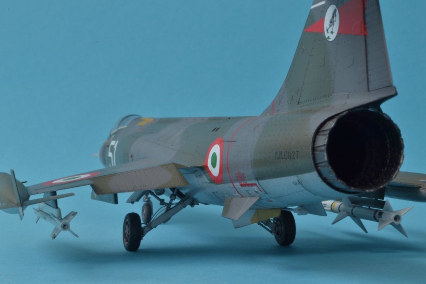

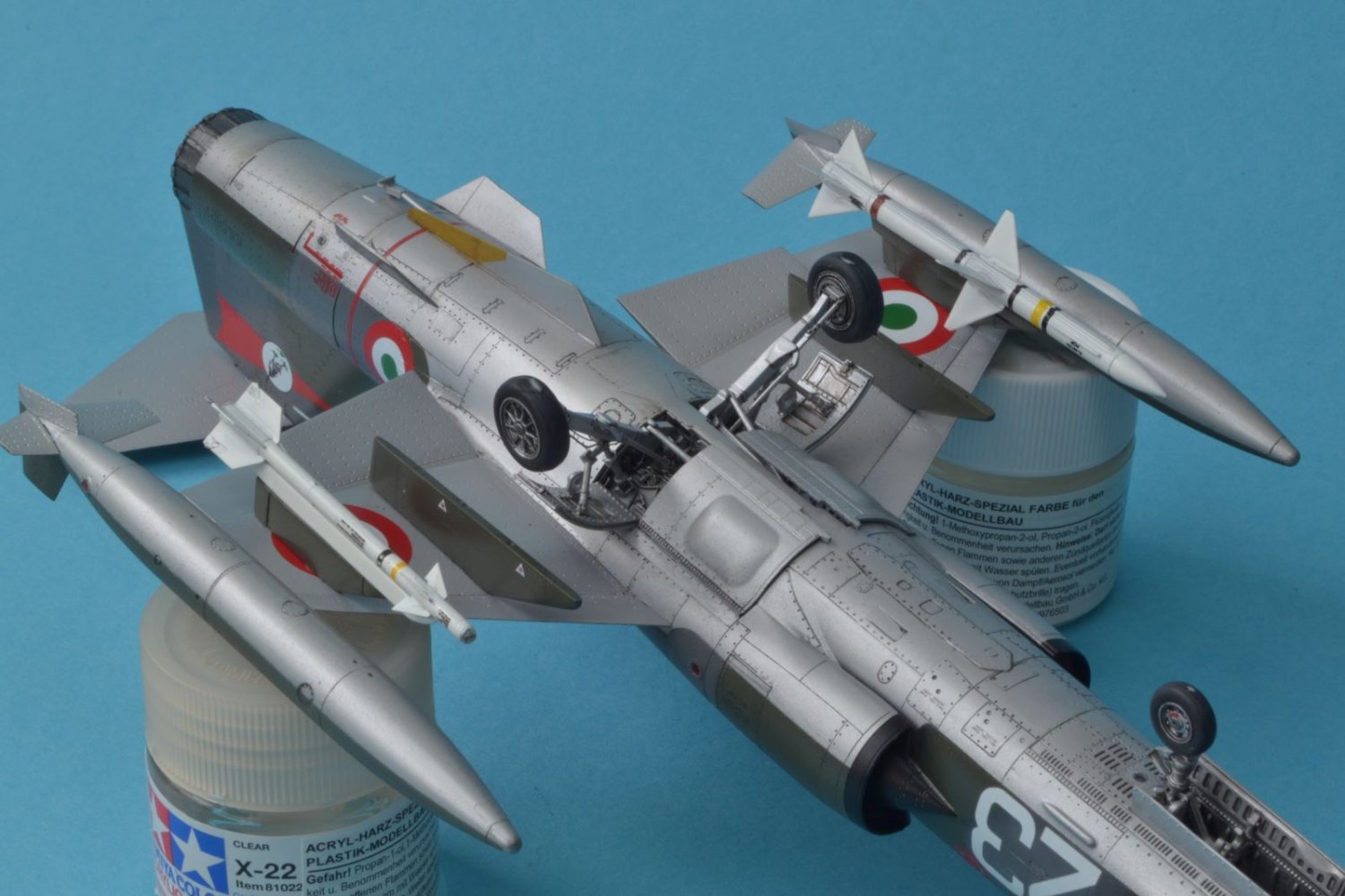
The colors that I used for the Italian NATO camouflage were Gunze H-69 (dark sea grey), Gunze H-309 (dark green) and Vallejo Metallic 'white aluminum' for the underside.

Beside the positive points, I am also listing what are, in my view, its few negative points:
- Overstated rivets on the wings which shouldn't be there;
- Incomplete range of details for the 'S' version;
- Absence of external loads and pylons;
- Decals with yellow/cream color in place of white for codes. I replaced them with after market decals.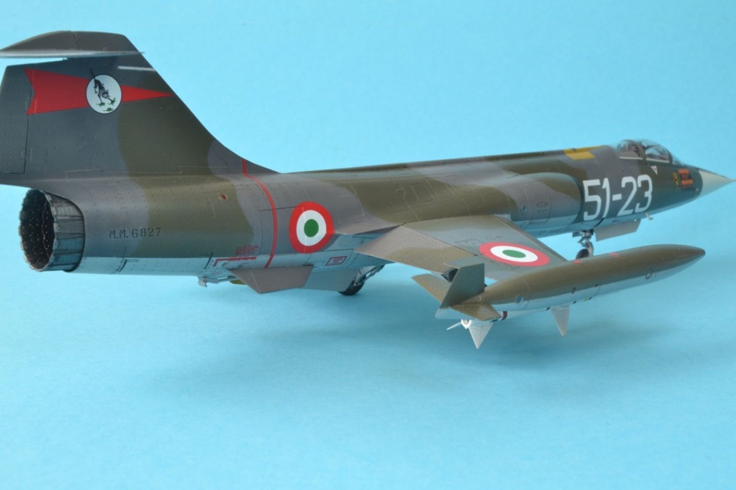
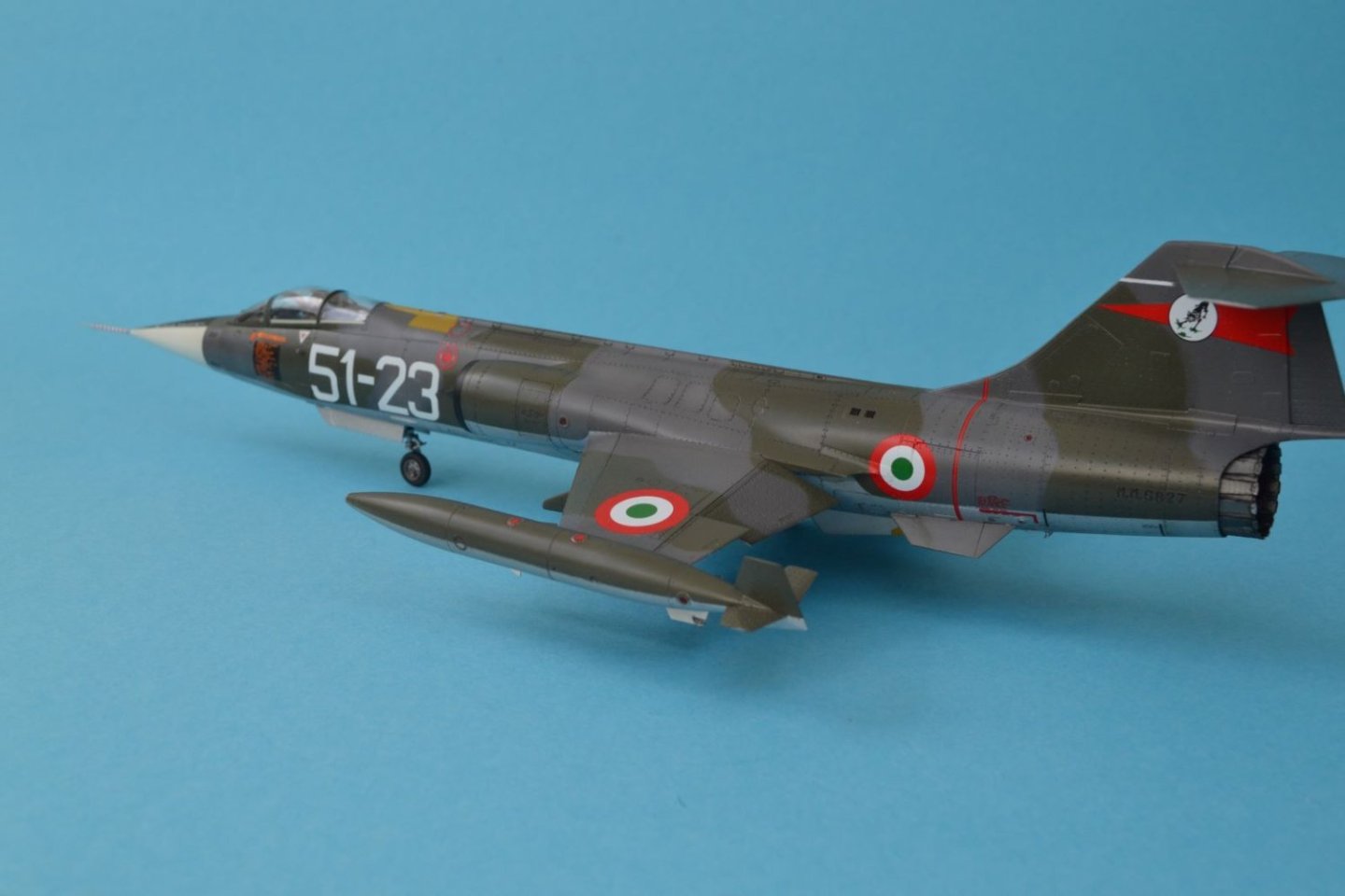
The grey paint of the camouflage was slightly post-shaded to reproduce the typical discoloration of this paint. The final finish was obtained by a coat of Tamiya flat clear XF-86 with some clear added to obtain a satin finish.

Little rivet trails and discolorations on the undersurface were obtained by oil colors.

I hope you like my model, thanks for the provided feedback and comments and suggestions are as always welcome.
Best regards,
Dan -
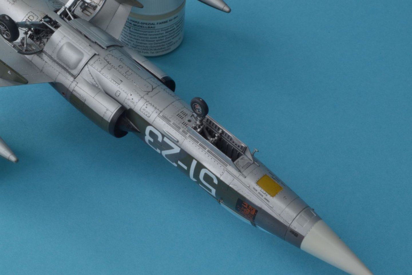
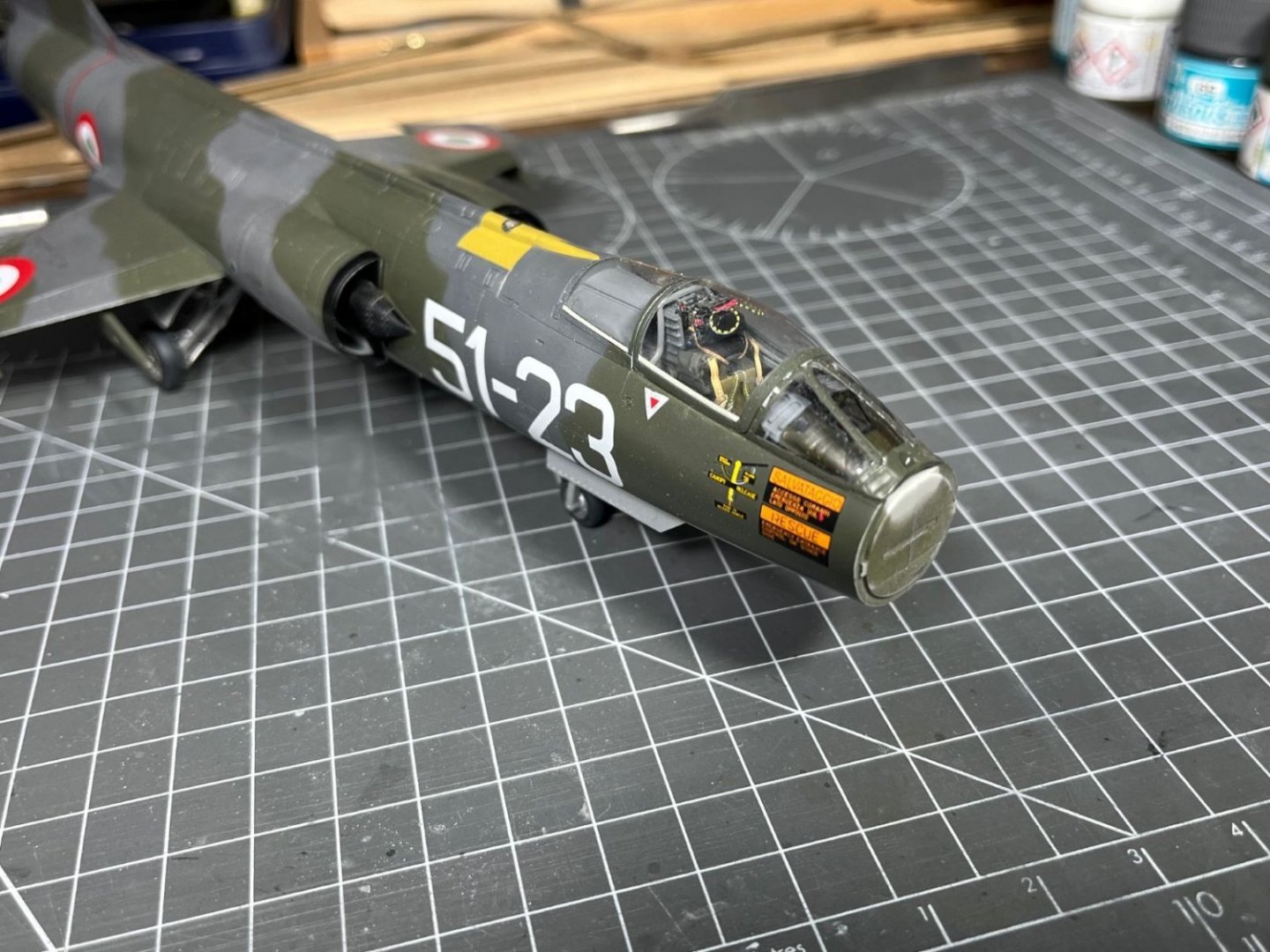
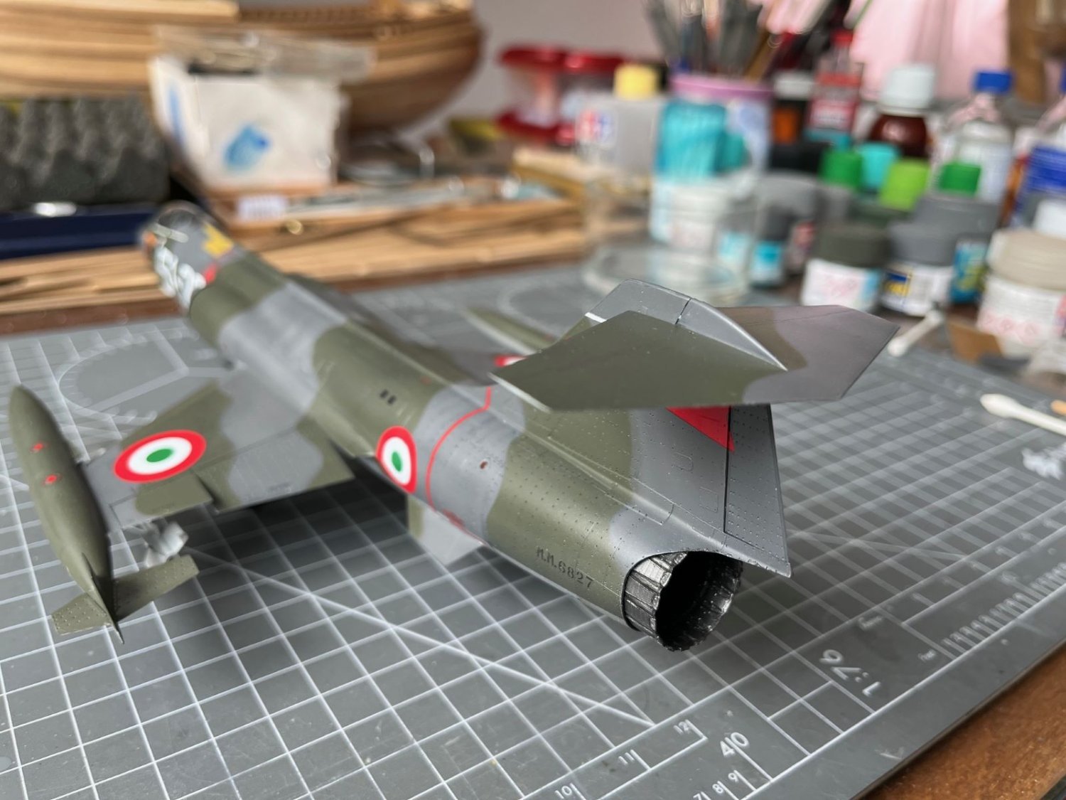
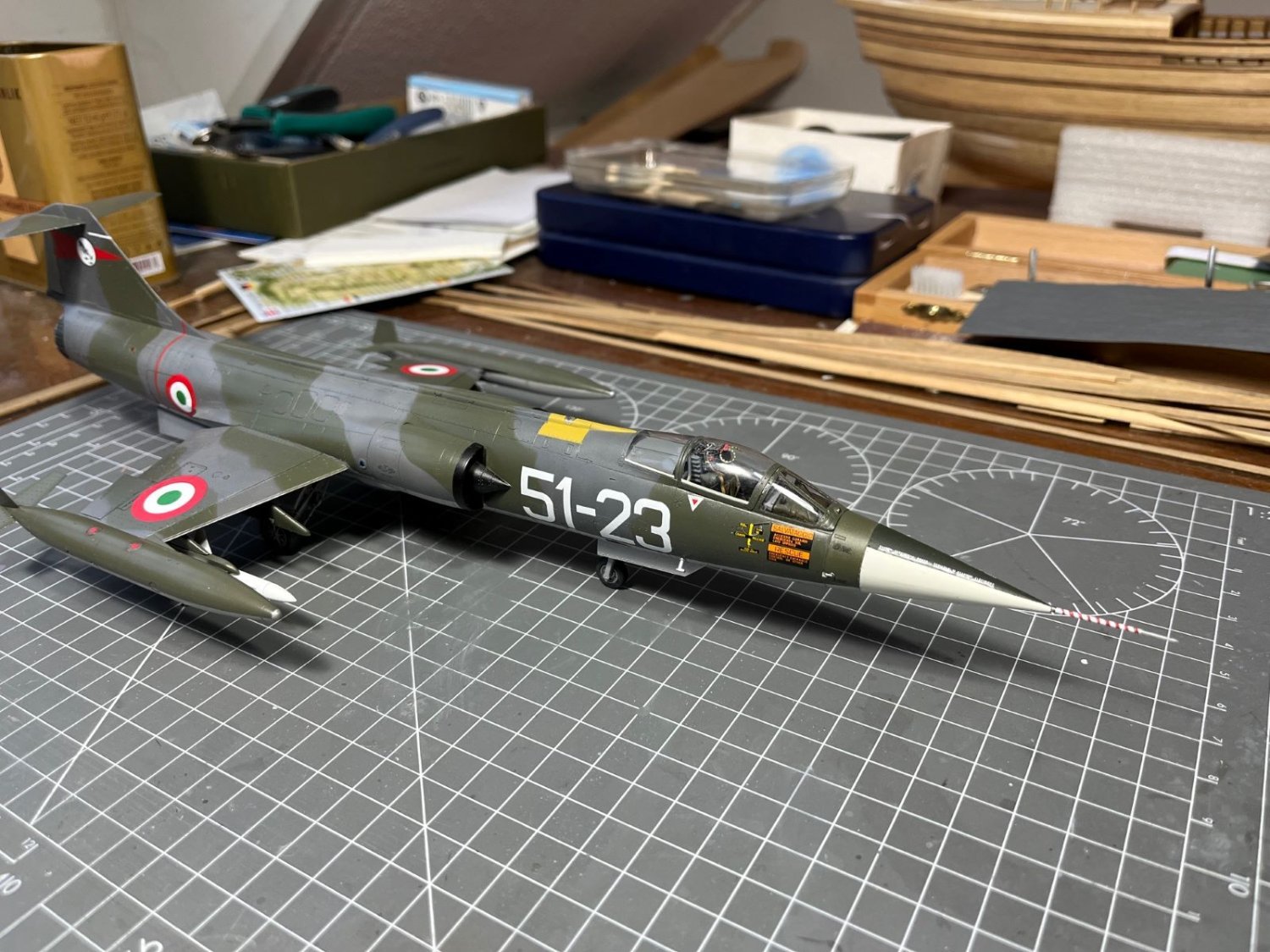
Hi there,
the last bits being assembled. The angle of attack sensor vanes glued in place with white glue;
The huge tip tanks that ruin the sleek shape of the plane:
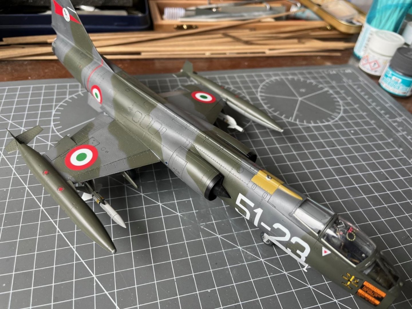
The stabilizer/elevator surface of the 'T' tail:

And finally the nose cone with the long pitot which I managed to knock off only a couple of times:
Next installment will be the last one and will contain the final pictures. Being the plane very long, it won't be trivial to take good pictures with all of it in focus.
Best regards,
Dan
-
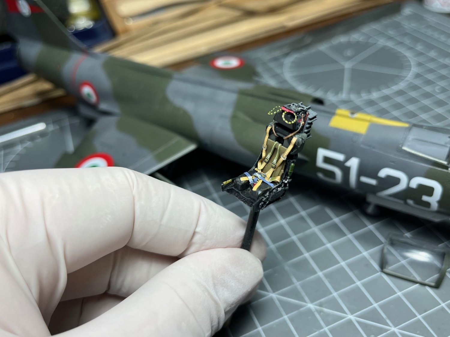
4 minutes ago, AJohnson said:
That is a very tidy looking bang seat Dan!
Thanks Andrew 😃! The Eduard kit was of top quality. Beside the photoetched things that are always a bit tedious to me, it was enjoyable to finish it.
Cheers,
Dan
- Old Collingwood, Egilman, Canute and 4 others
-
7
-
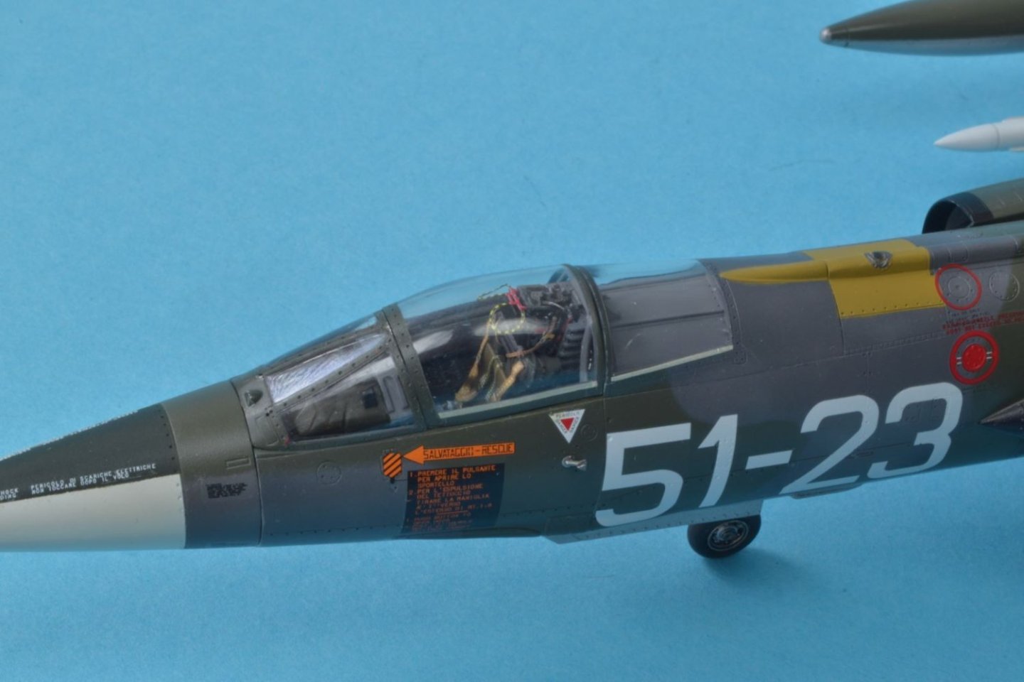
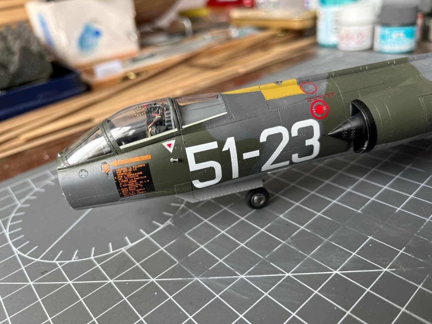
Hi there,
this time I concentrated on finishing the cockpit. I sourced the Eduard ejection seat M.B. mk7 to replace the one of the kit, which was overall correct, but very simplified. The Eduard resin is very nice (I wonder how they produce these things) and broken down in few pieces. As usual, to drape the photoetched harness made of steel was a serious test of my mental sanity. The finished product, painted and coated with a flat clear was nevertheless quite nice:

This is the seat tested inside the cockpit:
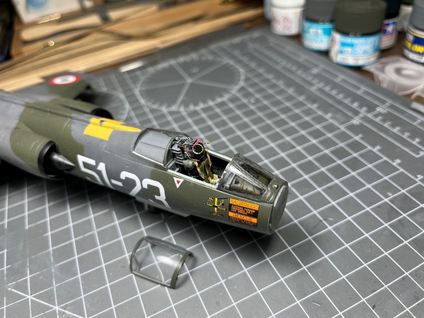
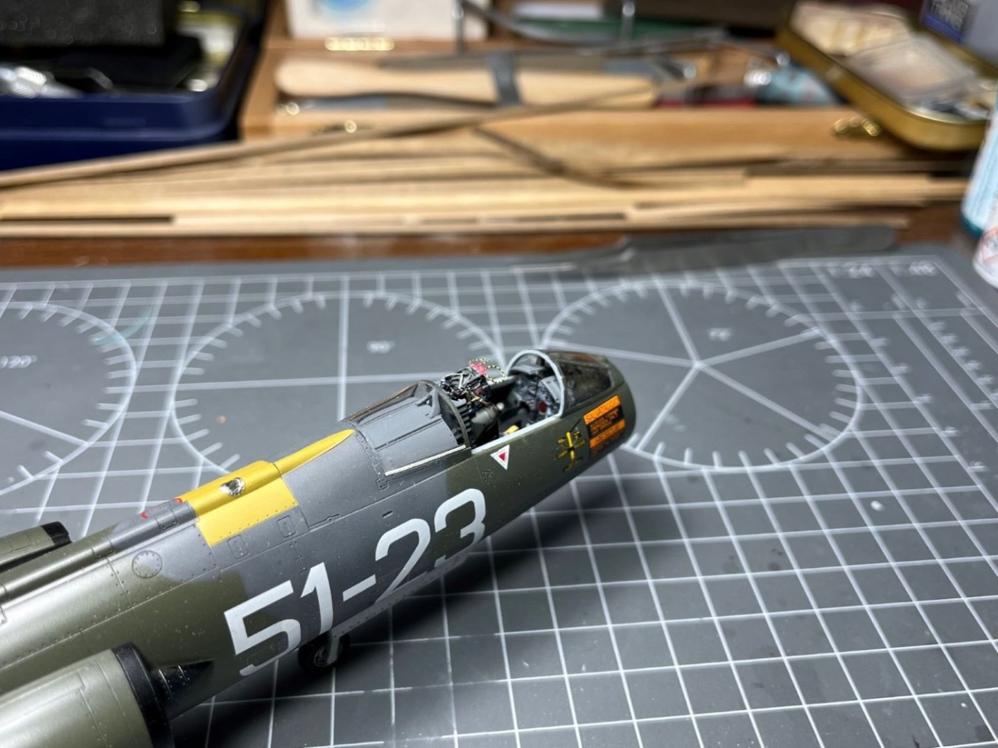
Finally, this is how it appears under the finished canopy:
That is all for today,
best regards,
Dan
-
Thanks for your explanations. Probably the kit design is flawed and the best action was what you did, i.e. lowering the LG bay. My comment about the position of the wing was aimed at trying to gain some fraction of mm by shifting the lower wing piece aft where the cut out of the fuselage offer more space (I had the impression from the pictures that this was possible). I am not assuming that the wing sits obviously too forward.
Good luck again,
Dan
- mtaylor, Old Collingwood, Dave_E and 5 others
-
8


AEG G.IV - Creature of the Night by DocRob - Wingnut Wings - 1/32
in Non-ship/categorised builds
Posted
The close-up pictures are impressive Rob.
Cheers,
Dan