


Gabek
-
Posts
278 -
Joined
-
Last visited
Content Type
Profiles
Forums
Gallery
Events
Posts posted by Gabek
-
-
-
On 12/8/2023 at 12:59 AM, aliluke said:
...Manitoba - been there, Winnipeg at minus 15C -
Hello Alistair,
What brought you to our fair (and frigid) province?! And you only got -15C? Come at the end of January/early February and we can give you -35! 🥶
Stay cool,
Gabe
- Keith Black, mtaylor, Glen McGuire and 1 other
-
 4
4
-
-
-
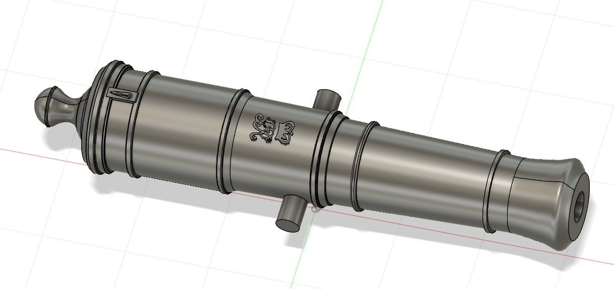
Final (?) product.
1:64 6-pounder Royal Navy Cannon - George III era
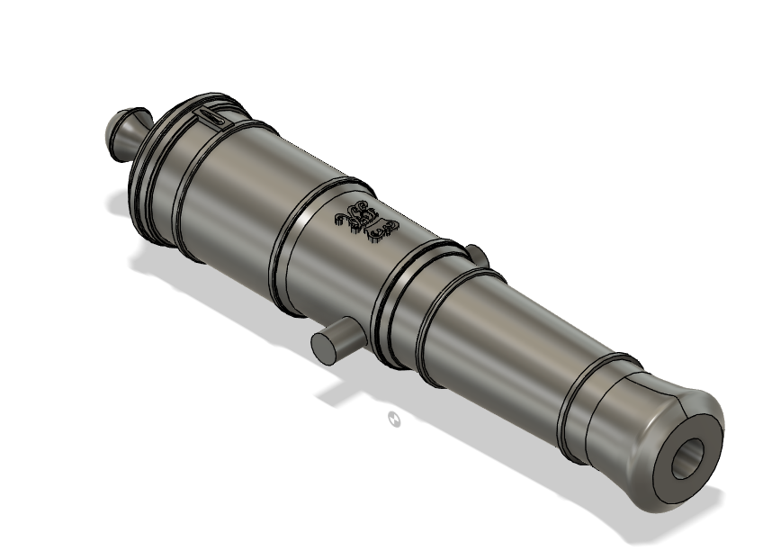
I printed these at 0.03mm resolution in Anycubic ABS+. If anyone wants the .cbddlp file created for these prints (with supports) just send me a message.
If anyone chooses to print these out I would appreciate a photo!
I hope this helps,
Gabe
- Knocklouder, mtaylor, scrubbyj427 and 1 other
-
 2
2
-
 2
2
-
On 9/23/2023 at 12:02 AM, Dr PR said:
I have seen this problem with Chitubox. With a single surface (like an "O") with a hole in it the hole is often filled in.
...
Since this seems to be a problem with different CAD programs and different slicers I suspect it is a problem in the STL file format, or at least the description telling how to create the STL object.
Hello everyone,
In response to people who have warned that there might be a split in the .stl where I created the complicated curved bodies I checked the meshes in Fusion 360 and I do believe that they are stitched correctly:
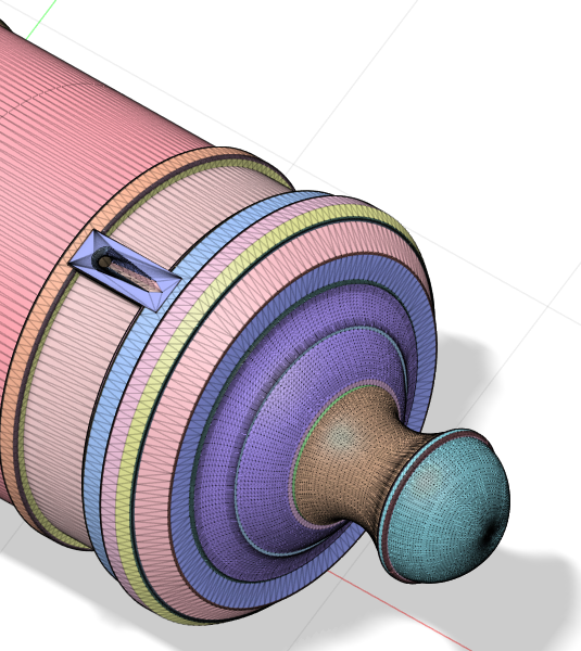
Thanks for your input, folks. I will be posting the .stl for this file shortly.
Clear skies and sharp tools!
- Gabe
- mtaylor and thibaultron
-
2
-
On 9/23/2023 at 12:02 AM, Dr PR said:
I have seen this problem with Chitubox. …
Thanks, Phil. I do use Chitubox on occasion so I'll make a point of checking for these errors.
Regards,
Gabe
- thibaultron and mtaylor
-
2
-
On 9/24/2023 at 4:44 PM, thibaultron said:
On the trunons (sp), move the outside supports to the ends. This gives better repeatability, and less chance of an oblong end.
Thanks! I had spotted that earlier and they were placed on the end like you recommend on this version.
Regards,Gabe
- mtaylor and thibaultron
-
2
-
25 minutes ago, Lieste said:
A single part joined at a semi-seam like that sometimes fails to print well. You may be better off with two halves - it is a problem for some slicers to have an edge which is outside to outside within the same part in a 'ring'. It can cause the bore to 'infill' rather than remain open at an edge in a 'random' point and can interfere with supports placement too. Two separate parts placed together so the bore isn't "inside" the outer perimeter of any single part can slice better in some cases. It doesn't have to be 'literally sliced in half - excising a narrow wedge from the lower surface 'below' the trunnions might be sufficient to avoid the problem, and better hides the 'seam' between the two elements.
I'm sorry, Lieste - I don't quite follow you.
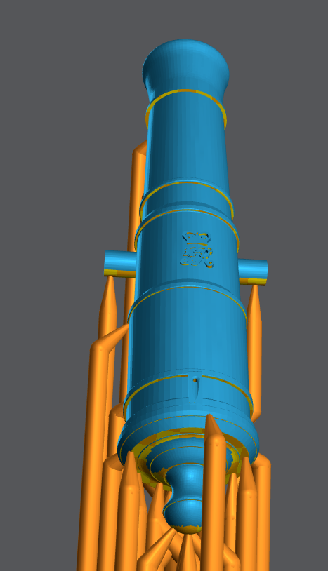
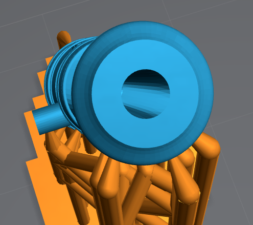
The lines on the cascabel and the muzzle appear to be artefacts of the drawing (Fusion 360), not seams in the model. I'm printing in resin at 0.03mm resolution and have yet to see the line and there isn't any kind of infill.
In the slicer (Lychee), here's what the model looks like:
- thibaultron and Knocklouder
-
2
-
36 minutes ago, Knocklouder said:
Those look relly good!! Are you still interested in the barter system, 20 cannons for 20 pounds lol, great cannons my friend. Ok ,I will go as high as 30 lbs for 20

LOL! I'll go 20 cannons for 10lbs, Bob!
- Knocklouder, mtaylor and thibaultron
-
3
-
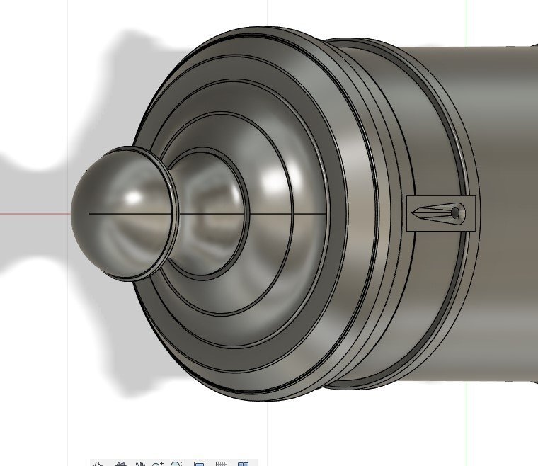
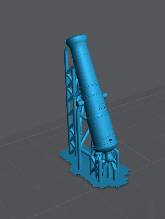
Hello folks,
Based on suggetions from @thibaultron and @allanyed, I've made some more modifications to the 6-pounder. Namely, I added the trough, reshaped the cascabel, and adjusted the breech rings. Here are a couple of screen shots. Once people are good with these latest changes I'll post the .stl and .cbddlp files for everyone to use.
When I feel up to it I'll make a gunlock for this cannon.
Regards,
Gabe
-
-
12 hours ago, allanyed said:
Hi Gabe
Thank you for sharing this. Will you be adding the trough around the vent? Do you or does any member know the vent diameter?
Allan
I actually just guessed at the vent diameter because the drawing I referred to in AotS Diana only showed the barrel with the gunlock. If you have diagram with the trough I can easily add it. To be honest, I knew that this detail would be almost invisible at 1:64 so I didn't fret too much.
- Gabe- Morgan, allanyed, thibaultron and 1 other
-
4
-
5 hours ago, thibaultron said:
Update long 24 pounder ….
Thanks for posting this, Ron!
- thibaultron and mtaylor
-
2
-
8 hours ago, Morgan said:
Very nice Gabe. 12 & 24 pounders next please 😜
Gary
Thanks, Gary
And they're on my list! Stay tuned.
Regards,
Gabe
- mtaylor, thibaultron and Morgan
-
3
-
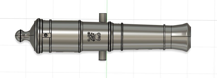
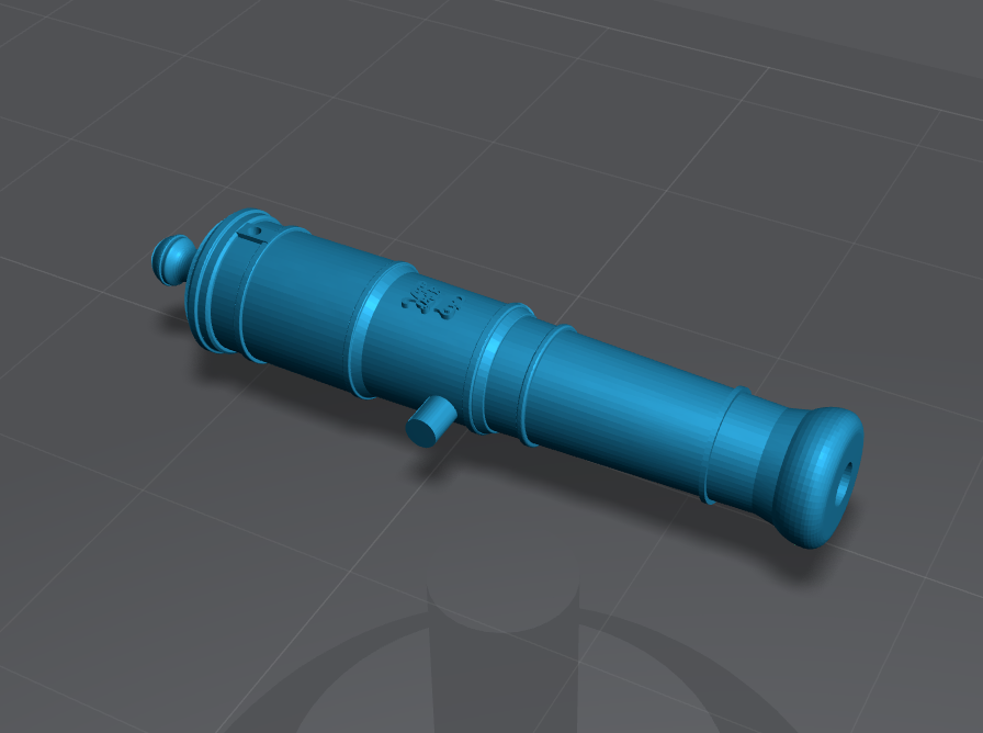
In answer to @Lieste 's rebuke of my first attempt at a cannon barrel, I have corrected the muzzle to what I hope is a more acceptable shape. I admit that I had incorrectly shaped the muzle. The lines you see in the muzzle would not be printed - they are simply artefact lines from revolving the complex shape of the muzzle. You see the same lines on the pommelion. These would not be printed as you see them.
Please let me know if these are acceptable. Attached to this is the .stl file for you to download. I will post a ready-to-print, supported model once people are satisfied that I have a correct cannon barrel.
Kind regards,
Gabe
- Lieste, scrubbyj427, Haliburton and 4 others
-
4
-
 3
3
-
3 hours ago, Lieste said:
Not especially convinced by the shape of the tulip, swell of the muzzle, or the muzzle rings and astragals.
As a *rough* approximation the swell should be half a calibre from the muzzle and occupy half the length from muzzle face to the greatest diameter, continuing into the tulip the arc of the swell and tulip should be tangent at their meeting. The Tulip form should be a larger radius curve smoothly transitioning from the middle of the neck of the chase (where the astragal is) to be tangent to the swell.
Details about the number and shape of mouldings between the muzzle face and swell vary according to the pattern, but the smooth flow of curves seems pretty universal, even as their proportions change.I based this model on diagrams that were supplied to me, which I quite obviously didn't even follow all that faithfully. Yes, I can see the hideous mistakes, particularly at the muzzle. My apologies for sharing something so inadequate. I won't bore you with some of the mitigating circumstances that contributed to this failure. Thank you for your corrections. Please disregard my work.
- thibaultron, dvm27 and mtaylor
-
1
-
 2
2
-
1 hour ago, AJohnson said:
Congratulations on your Grandson Gabe!
 I hope you buy him plenty of model kits to build and keep him busy / away from smartphones/gaming consoles as long as possible when the he is older!
You did well to get anything done on the Agassiz with all that going on! Looking good. 👍
Thanks, Andrew! I'm pretty sure that my grandson be immersed in models…whether he likes them or not! 🤣. That and fishing! 🎣🤣
-
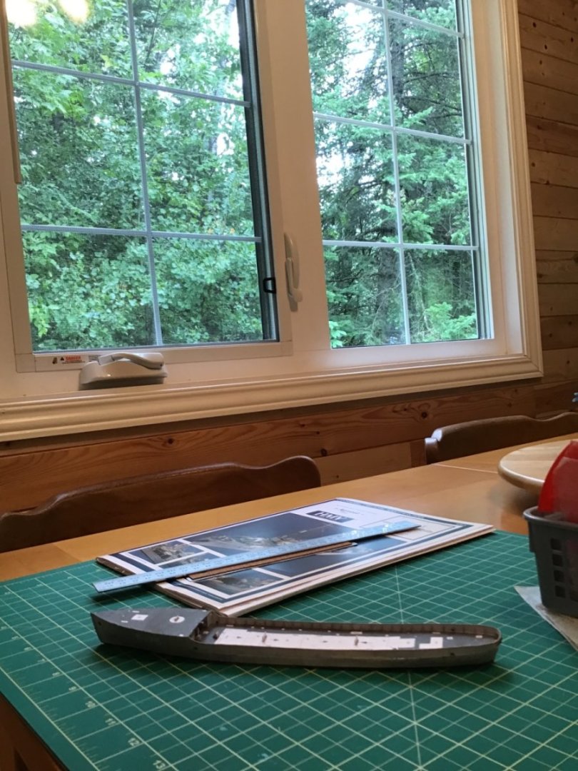
Fourth trip to the cottage
Wanting to be close to home for the birth of our grandson and the subsequent visit from my sister and mother have happily kept us away from the cottage. By the way, here's our little admiral, Duncan:

(and because of the modeller in me I have already researched and located plans of the Royal Navy Admiral Adam Duncan's flagship at Camperdown, HMS Venerable, and purchased the Trumpeter model of the modern day HMS Duncan…)
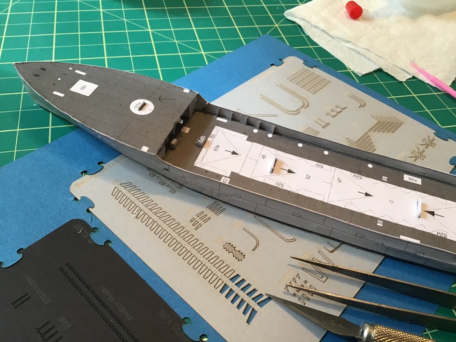
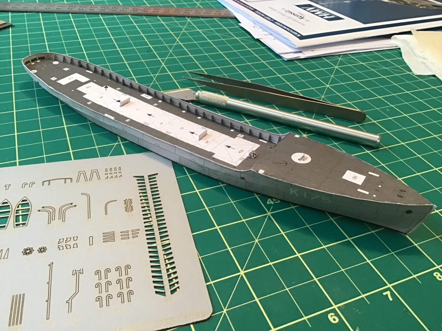
On to the HMCS Agassiz/Wetaskawin…We only stayed at the cottage long enough to mow the grass (and much taller month-old poplar trees) and a few chores so in the lulls I managed to attach the bulwark stays(?). This is when I the laser cut kit that I purchased paid for itself…again! I almost think it is a necessity to get the kit if you want to build this model. These tiny parts were painful enough to install without having to worry about cutting them out accurately, etc. The thicker card stock of the laser kit made these pieces nicely stiff and resistant to the somewhat ham-fisted manoeuvrings I put them through. Their thickness also helped in squaring them to the bulwarks.
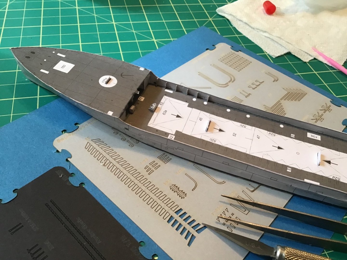

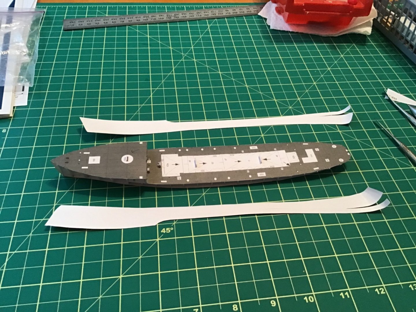
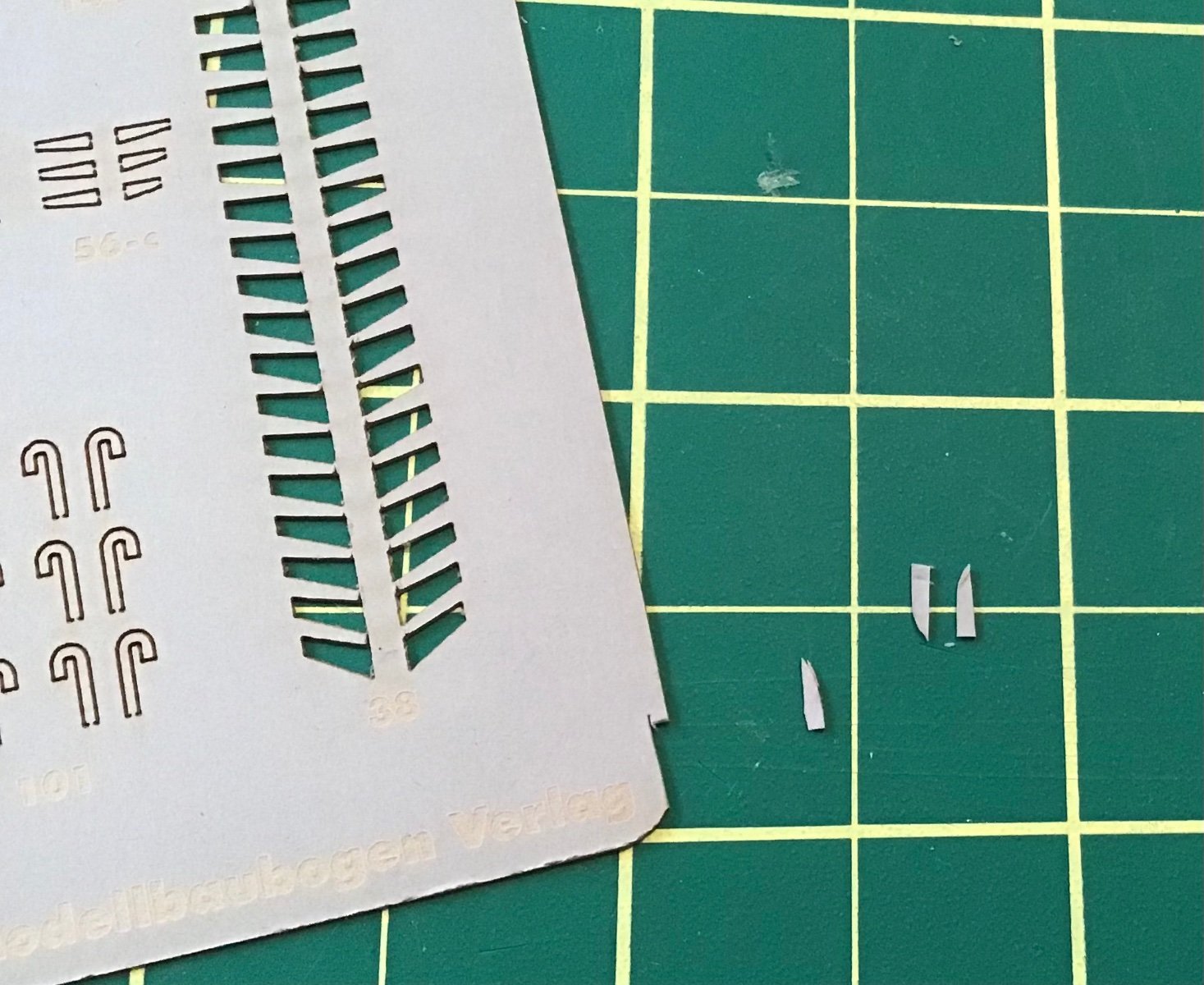
Outboard of the transom were two flanges similar to the bulwark stays that likely support the depth charge chutes. In real life these are likely thinner than the bulwark supports so they weren't included in the laser cut kit…but I thought it would be advantageous to make them thicker. So, I sliced off a couple of these from the edges of the laser cut card.
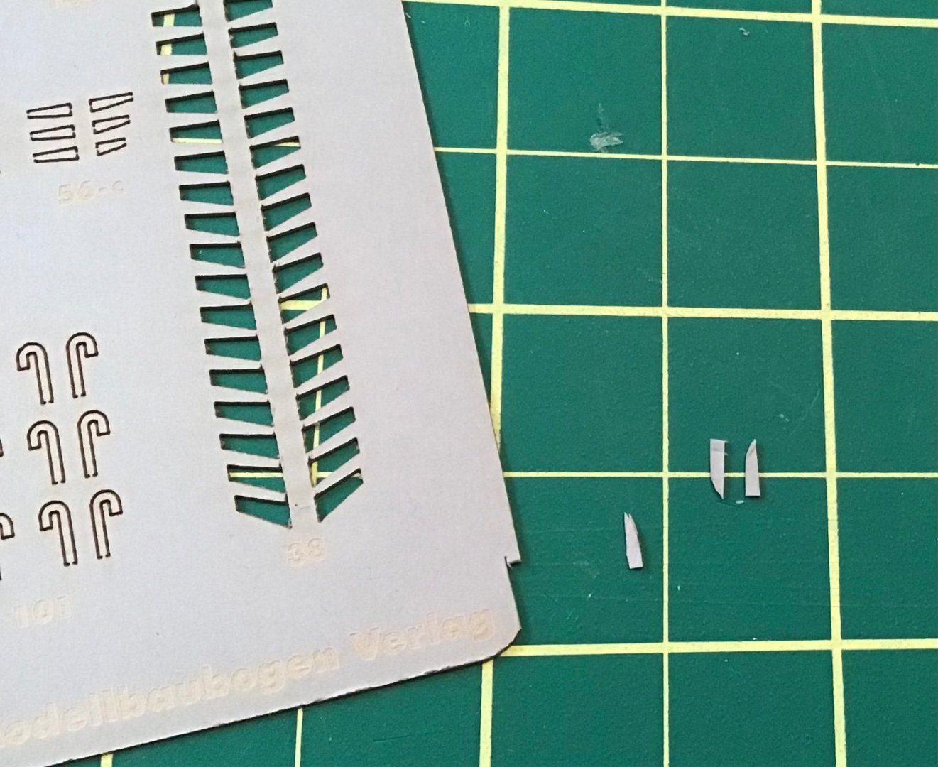

(OMG! Getting in close sure shows off my crummy workmanship!)
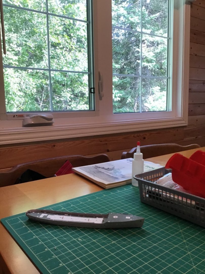
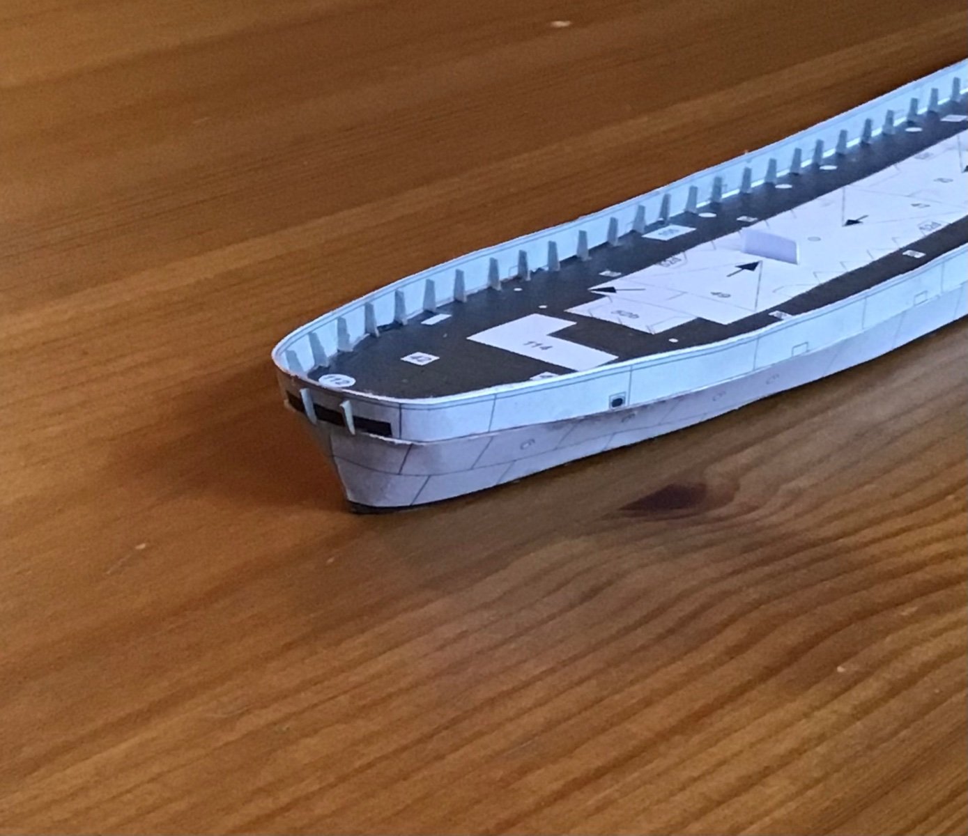
I had time to glue in the stem…
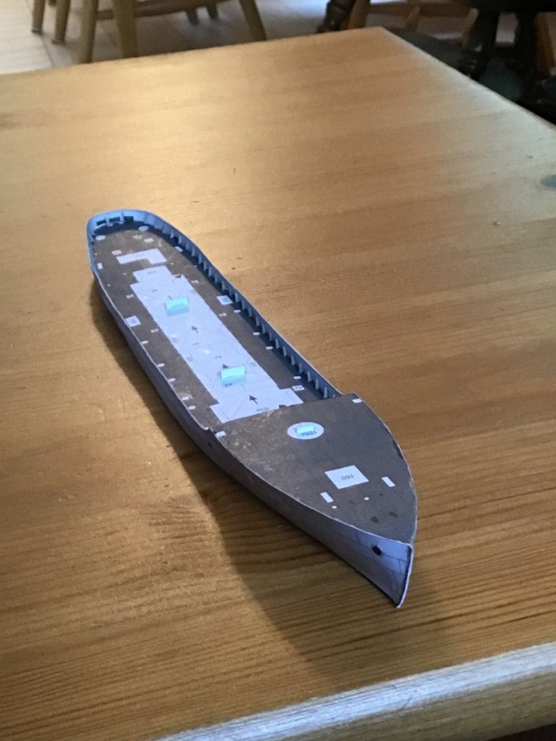
And that's how she sits until our next visit…
Clear skies and sharp tools!
- Gabe
- VitusBering, ccoyle, king derelict and 5 others
-
8
-
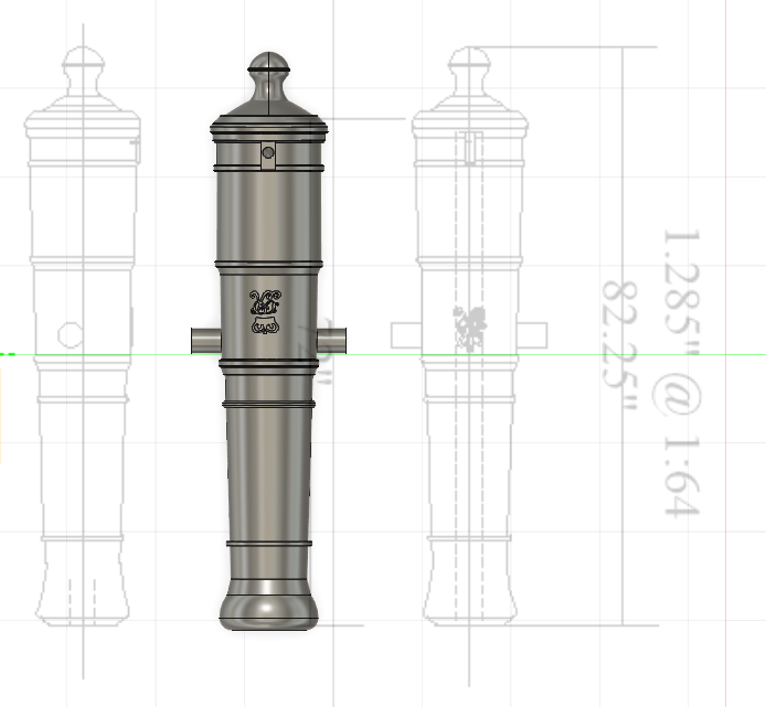
Hello modellers,
My friend and fellow Manitoban, @Knocklouder , asked if I could print up some 6-pounder cannons for his HMS Pegasis (Amati, 1:64). I based the following design of the 6-pounderm found in Anatomy of the Ship: The 24-Gun Frigate Pandora. I did not include a gunlock in this design - just a simple touch hole. The emblem on the cannon is George III but I think it could pass for the very similar George II - particularly at smaller scales.
This file was created in 1:64, but can be scaled up or down as needed. Attached are the .STL and the .cbddlp files for anyone who wants to print it off themselves. The .cbddlp is pre-supported. I used Anycubic ABS+ on an Elegoo Mars printer and had very good results - I can supply the print parameters on request.
Hope this helps,
Gabe
- thibaultron, Haliburton, bruce d and 10 others
-
12
-
1
-
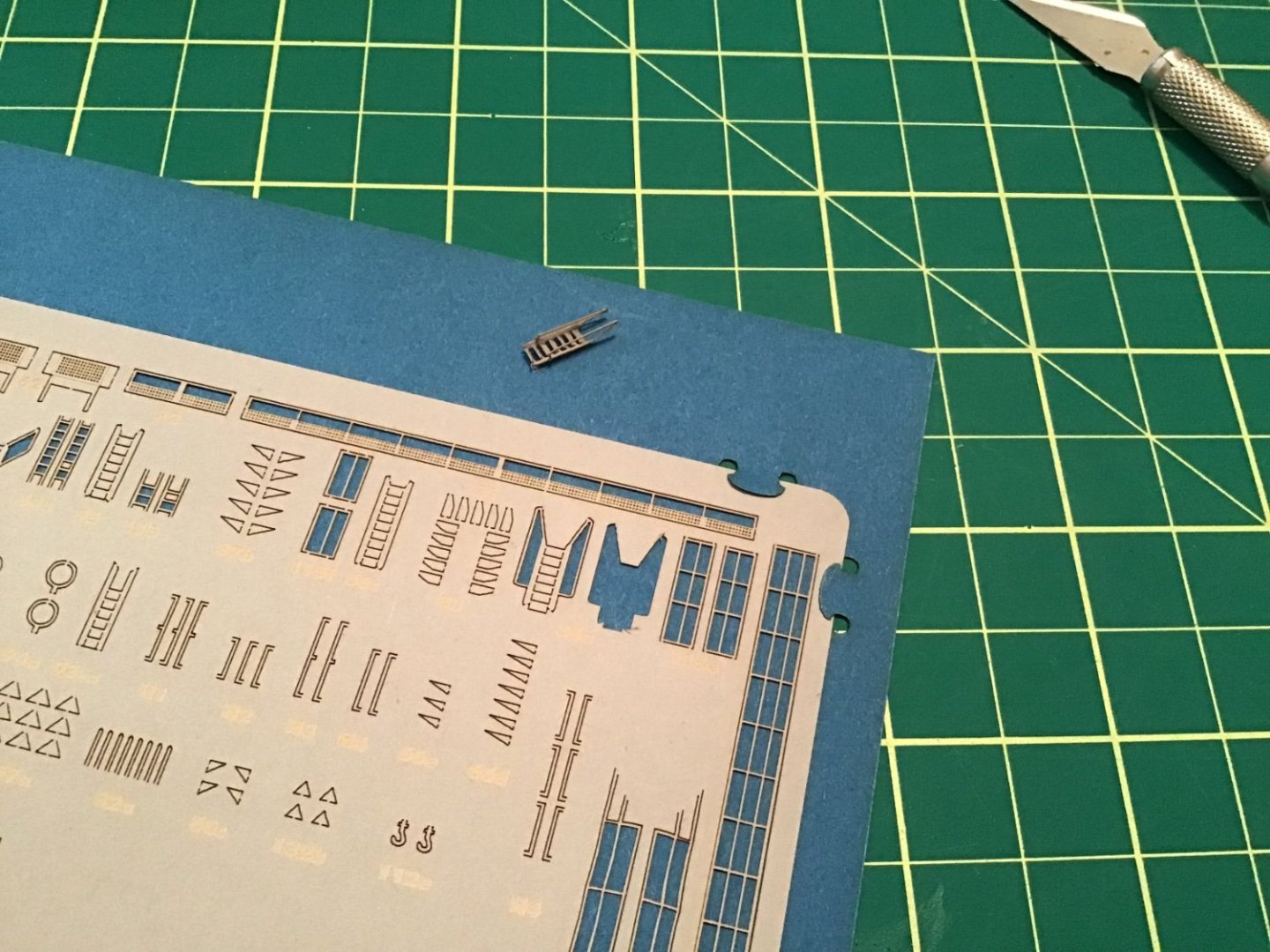
Third trip to the cottage
Tiny steps…
The next pieces, according to the plans, were the ladders to the forecastle. These would be the first pieces from the laser cut set to be used. I am very impressed with this set as it is well labelled and has an index and diagrams of all the sheets to help you search.
After carefully fussing for over an hour with the first tiny ladder, attempting to bend those blasted minuscule treads into place I was not in the mood to bend the second one right away. Nonetheless, I carefully glued the first into place and as I saw those delicate rails sticking up above the forecastle I knew they would certainly be crushed as I continued with the rest of the model. I carefully took it off before the glue dried and stored it in a pill bottle for now.
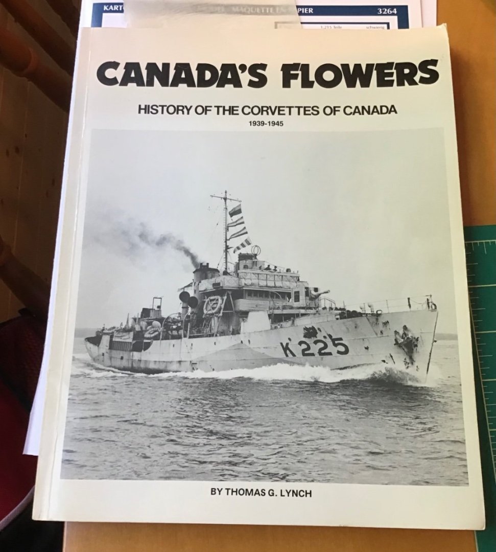
Big steps…At this point I had a choice of which of the four ships I wanted to build so I read over one of my reference books on flower-class corvettes that I had brought up to the cottage. I have purchased several books on these ships because I will be building the Revell 1:144 HMCS Snowberry kit in the near future - my first plastic model in 50 years.
HMCS Wetaskawin was mentioned as having sunk a u-boat early in the Battle of the Atlantic, so I went with that ship for this model and cut out the lower hull and gunwale pieces. Clay modelling tools were used again to create curves to match the deck shape.
Over two days I alternately glued hull sections. First the lower hull, one side at a time. To thicken the gunwales and provide printed details on the inboard view, the model requires an inner gunwale be glued to align with the outer section. And then I made the stupid mistake of trimming off some lower hull that was sticking slightly above deck on the port side before gluing down the gunwales. This has left a little gap that I may have to address.🤬Fortunately, there are three more gunwales that I have to try and patch/fix the issue.
I should mention that I debated at length about cutting out the scuppers. I regret my decision not to. I think the model would have looked better and now that I completed these steps it will be too difficult to do a good job of cutting them out.
And this is how the model sits until next visit:
Clear skies and sharp tools!
- Gabe
- GrandpaPhil, mtaylor, king derelict and 4 others
-
7
-
Beautiful work, Bruce! Simply masterful.
Clear skies and sharp tools,
Gabe
- FriedClams and mtaylor
-
2
-
18 minutes ago, AJohnson said:
That looks very nice, congratulations!
Thanks, Andrew!
Much appreciated.
I see you have a Mosquito in your builds…I've got one on the shelf that's itching to be built! It's either the Mossie or the HMCS Snowberry sitting right beside it that I'll open up soon.
Clear skies!- Gabe
-


The Mayflower by Knocklouder - Amati - 1:60
in - Kit build logs for subjects built from 1501 - 1750
Posted
In Canada we say, "Give 'er!"
Ok Bob, just GIVE 'ER!
Gabe