


Doc Watson
-
Posts
39 -
Joined
-
Last visited
-
 Mr Whippy reacted to a post in a topic:
HMS Fly by Doc Watson - Amati/Victory Models - 1:64
Mr Whippy reacted to a post in a topic:
HMS Fly by Doc Watson - Amati/Victory Models - 1:64
-
mugje reacted to a post in a topic:
HMS Fly by Doc Watson - Amati/Victory Models - 1:64
-
Pitan reacted to a post in a topic:
HMS Fly by Doc Watson - Amati/Victory Models - 1:64
-
oakheart reacted to a post in a topic:
HMS Fly by Doc Watson - Amati/Victory Models - 1:64
-
ESF reacted to a post in a topic:
HMS Fly by Doc Watson - Amati/Victory Models - 1:64
-
Doc Watson reacted to a post in a topic:
HMS Indefatigable 1794 by Blue Ensign - FINISHED - Vanguard Models - 1:64 scale
-
Doc Watson reacted to a post in a topic:
HMS Indefatigable 1794 by Blue Ensign - FINISHED - Vanguard Models - 1:64 scale
-
Prowler901 reacted to a post in a topic:
HMS Fly by Doc Watson - Amati/Victory Models - 1:64
-
Doc Watson reacted to a post in a topic:
HMS Indefatigable 1794 by Glenn-UK - Vanguard Models - 1:64
-
The Gimps Chimp reacted to a post in a topic:
HMS Fly by Doc Watson - Amati/Victory Models - 1:64
-
 The dockyard foreman caught a workman trying to steal some grog and put him in jankers for a week, either that or someone has had a bout of flu!?!?!. Just about recovered and some progress with the ships lanterns which should be done by next week and I finally have a plan for the rear of the boat.... cutting wood as we speak. Avast me hearties!
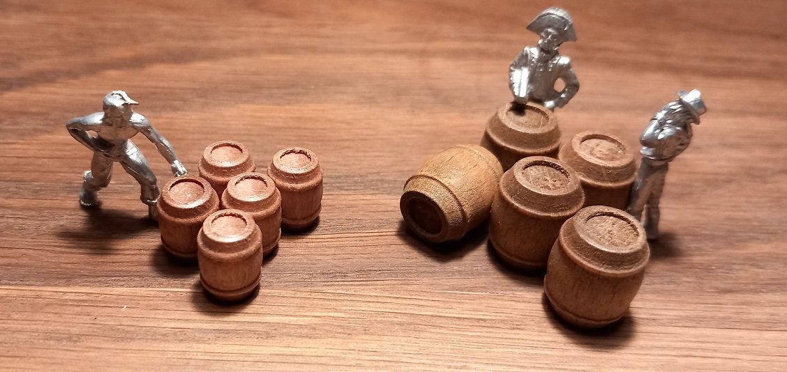
- 29 replies
-
- 6
-
-
- Fly
- Victory Models
- (and 1 more)
-
Doc Watson reacted to a post in a topic:
HMS Fly by aliluke - Amati/Victory Models - 1/64
-
Knocklouder reacted to a post in a topic:
HMS Fly by Doc Watson - Amati/Victory Models - 1:64
-
Doc Watson reacted to a post in a topic:
HMS Indefatigable 1794 by Glenn-UK - Vanguard Models - 1:64
-
Doc Watson reacted to a post in a topic:
HMS Sphinx by Delf - Vanguard Models - 1:64 scale
-
Doc Watson reacted to a post in a topic:
Higaki-Kaisen by Ekis - FINISHED - Woody Joe - 1:72
-
Effect in the ship.... I think it looks convincing.... Lantern01.mp4 Avast me hearties!
- 29 replies
-
- 3
-
-
- Fly
- Victory Models
- (and 1 more)
-
LED light inside the ink tube of a bic pen..... Lantern03.mp4 Avast me hearties!
- 29 replies
-
- 1
-
-
- Fly
- Victory Models
- (and 1 more)
-
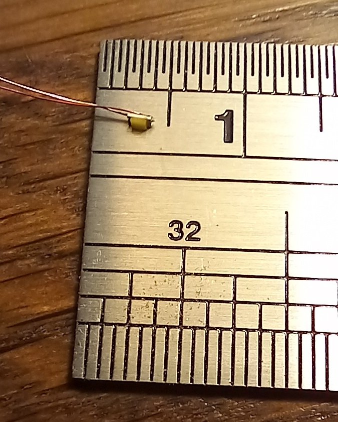
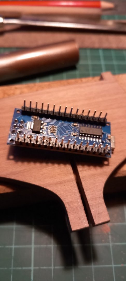
The LED lights have arrived and have been tested!!! They are small enough (I think) to use as candle lights and a quick program using an Arduino proved the flickering effect, the light is a little to 'white' but am experimenting with resistors and 'filters' (by filters I mean a light wash of oil paint on the LED) to soften the colour. The wire is 0.1mm and insulated with a coat of something (clear lacquer or plastic?) which has to be scraped off with fine sandpaper. Should be no problem replicating a lantern and the wires are 20cm long to allow each light to be located and the wires fed into the lower hull where they can be then soldered to 'more substantial' wire which will then be passed through the keel into a display 'box' holding the Arduino and batteries to run it. I also had a horrible idea of adding a real time clock, mp3 player module and speakers in the shallow box display base and the Arduino would use the clock to ring out the bells every 30 minutes, a sort of maritime clock. 8 bells!!!!! end of watch! Avast me hearties!
- 29 replies
-
- 3
-
-

-
- Fly
- Victory Models
- (and 1 more)
-
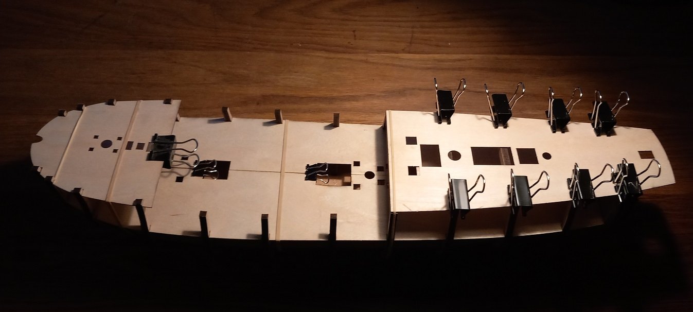
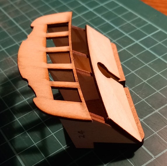
The transom assembly from the kit...the gap is to be planked. I notice that Blue Ensigns window was walnut sheet. I decided to dry fit the decks and the beams, remembering to widen the deck slots for frame 12. Decks fit very well. Avast me hearties!
- 29 replies
-
- 9
-
-
- Fly
- Victory Models
- (and 1 more)
-
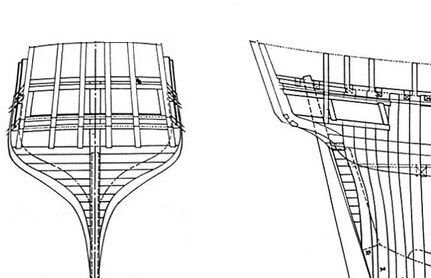
Thanks SpyGlass, not only do the outer pieces need to be inline with the deck which curves on top and the angle of the deck viewed from above but the rear also has a curve. I'm going to make 6 transom frames as shown below. (plans from HMS Bounty) each frame will be 3mm walnut (what else would it be!) and will sit between the window frames of the transom. Not sure about the horizontal framing yet. Avast me hearties!
-
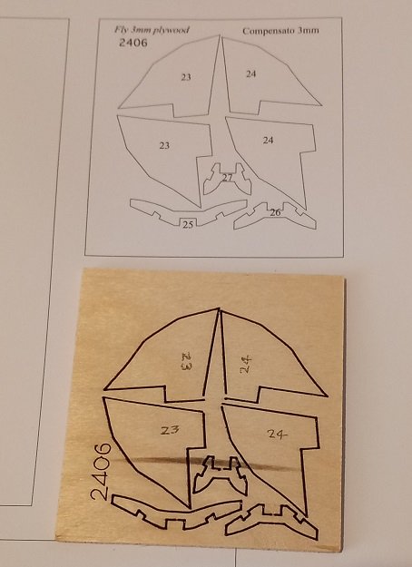
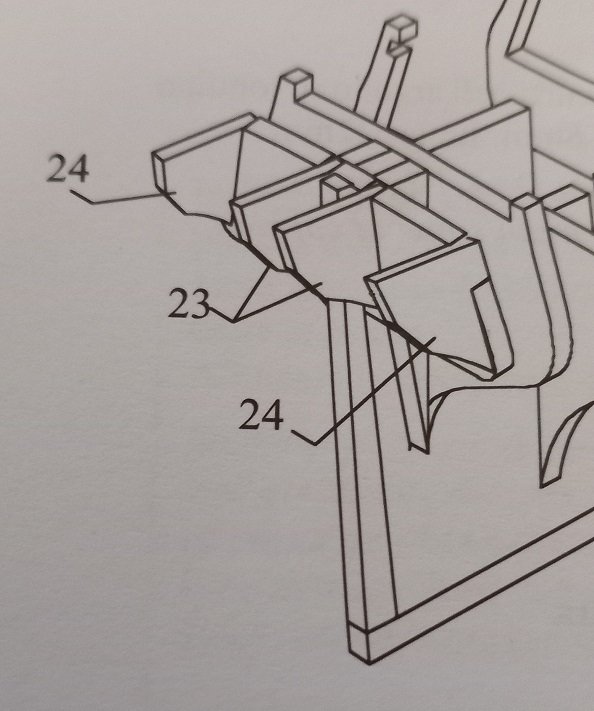
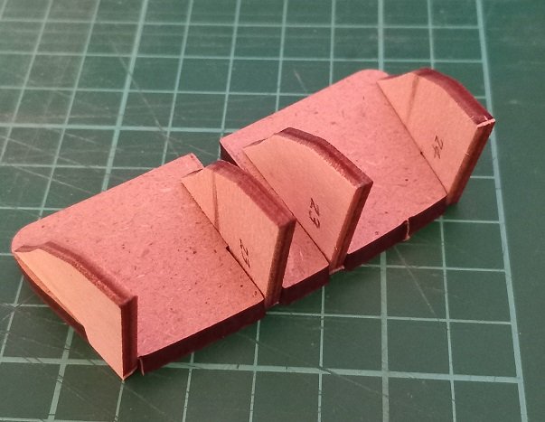
Frame 13 has 4 plywood pieces which form the transom area. Parts 23 and 24 look very similar so marked them... ...and dry fit on frame 13. Still thinking about how to open up the cabin area here. Avast me hearties!
- 29 replies
-
- 3
-
-
- Fly
- Victory Models
- (and 1 more)
-
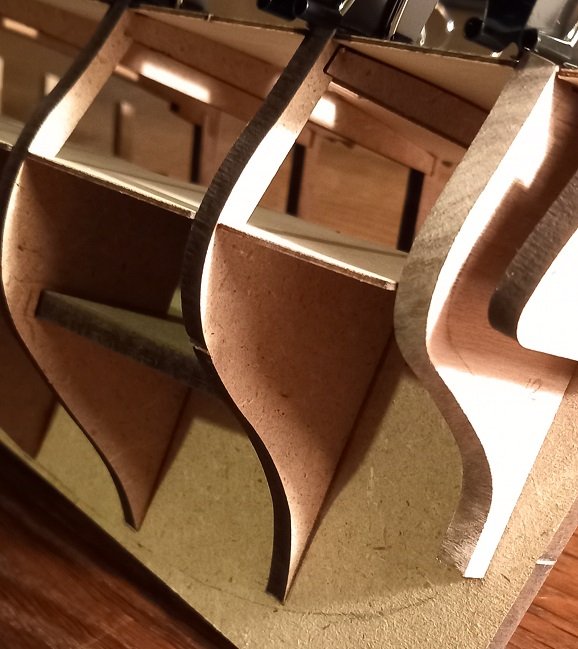
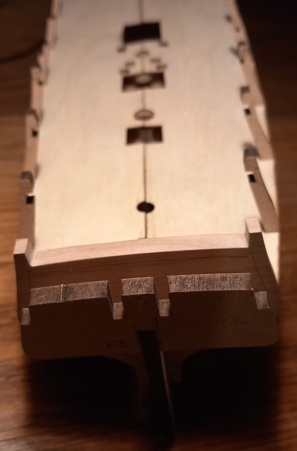
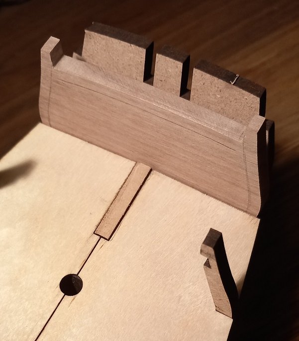
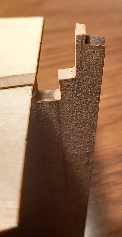
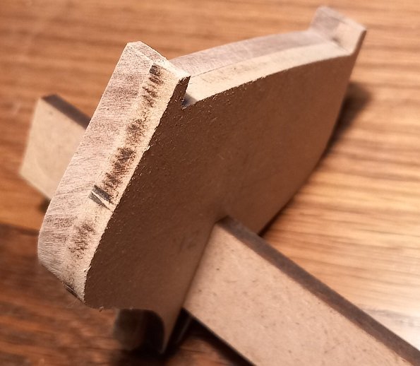
Cut the keel around the captains cabin and reassembled to mark the deck level on frame 12. Frame 13 is a little wonky! not a sniff of glue anywhere! And ready to mark the deck line on walnut frame 12... I have left the cut MDF slightly proud of the deck to be faired later after gluing the frame assembly together. And below is the cut keel with 6mm width for frame 12 and a 'step' was left for location of frame 13. I now need to study plans and decide how to extend the rear of the hull to the transom, a new walnut frame 13 is calling from across the waves. Avast me hearties!
- 29 replies
-
- 1
-
-
- Fly
- Victory Models
- (and 1 more)
-
SpyGlass, the MDF frame 12 has the deck height marked on it, I haven't marked it on the walnut part yet and will probably do it with the frames and deck assembled. After all that cutting I must have gotten a little carried away. Avast me hearties!
-
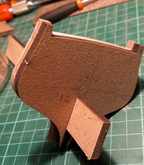
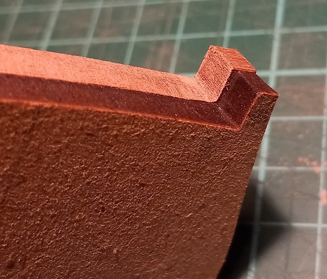
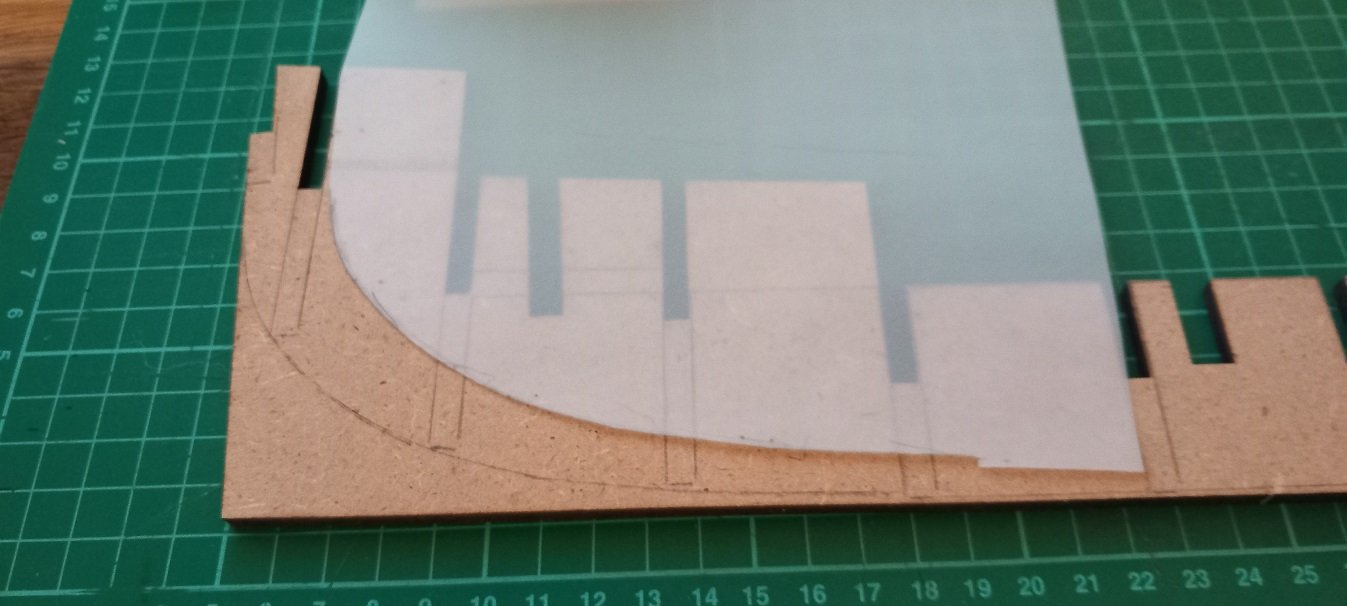
Finally..... Also marked 4mm inside lines for removal but a dry fit on the keel is required first. I also need to chamfer the edges and will delay removal of the inner section until I know how much bevel is required. Avast me hearties!
- 29 replies
-
- 2
-
-
- Fly
- Victory Models
- (and 1 more)
-
allenyed, again thanks for the information but as its so low in the ship I wont be lighting (or modelling!) below the MDF 'deck'. DavidG, got them here... https://www.amazon.co.uk/dp/B08ZH98BRJ?psc=1&ref=ppx_yo2ov_dt_b_product_details Will have them tomorrow and will test them. Finally got the slot for the keel filed to size. I used a piece of the 'waste' MDF as a guide and PVA'ed some 600 grit paper to one edge to get the end of the notch square. Now the slot is done I can clamp and file to final shape. Avast me hearties!
- 29 replies
-
- 4
-
-
- Fly
- Victory Models
- (and 1 more)
-
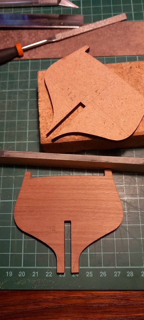
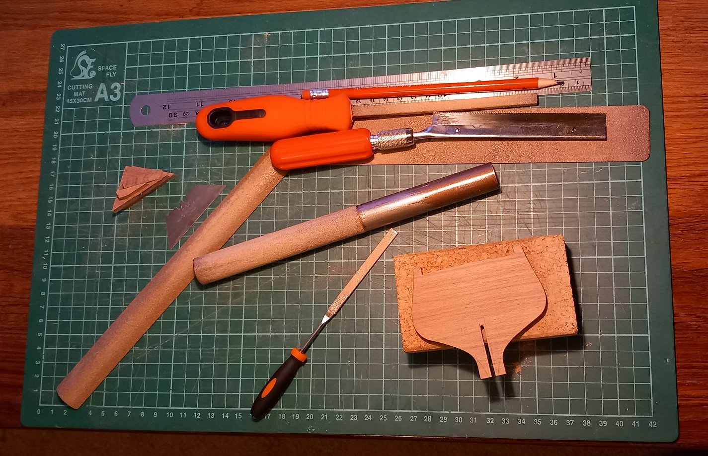
After a few hours... getting there... Once the keel slot is cut to the correct size I will start modifying the MDF keel piece and plan the cutting of the 'inside' of frame 12. Walnut is hard and the only power tool available in my workshop is the Mk I human body. By workshop I mean an A3 420mm x 270mm cutting mat with a rule that all tools/parts must only be on the mat! LED lights ordered and arriving in a few days. 10 of each for testing. hope there small enough!!!!! both 'warm white' in colour and I will control them with this.... Its an Arduino 'nano' clone which can be programmed to supply voltage to the LED's at a frequency of about 500Hz. I will start designing an LED lantern first, should be fun simulating the flicker of a candle. Edit: Quick google later and a candles frequency is anywhere between 5 and 12 Hz... Avast me hearties!


- 29 replies
-
- 6
-
-
- Fly
- Victory Models
- (and 1 more)
-
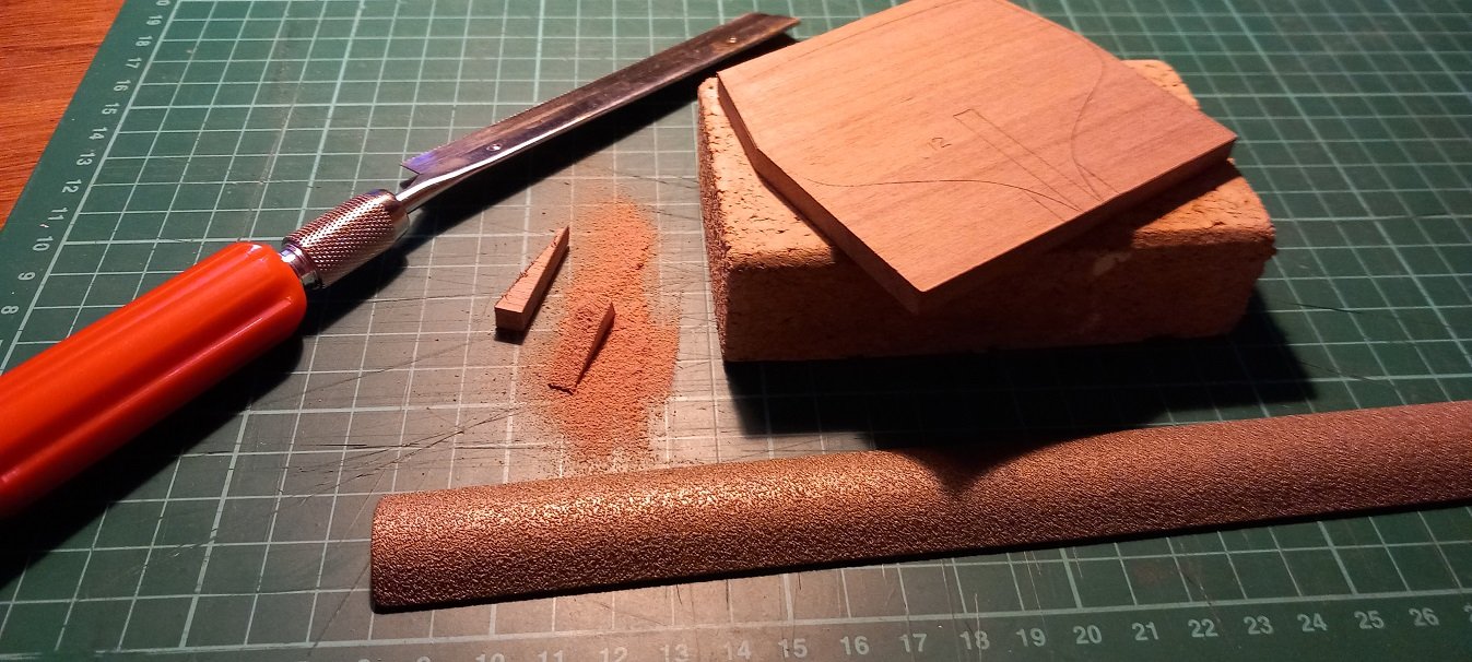
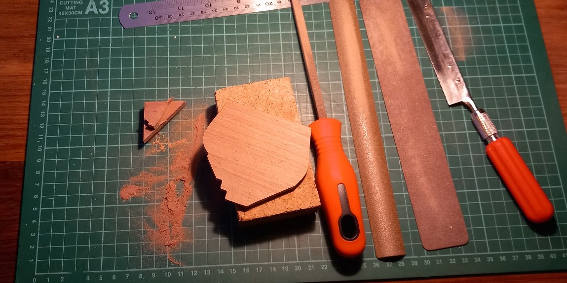
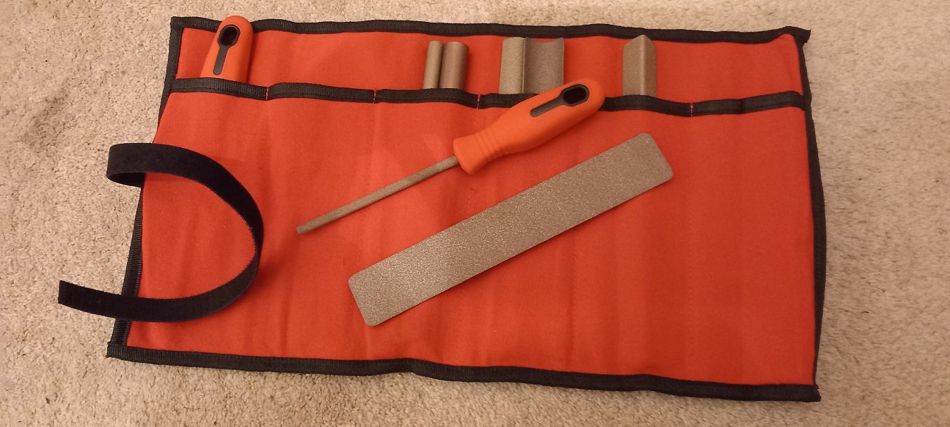
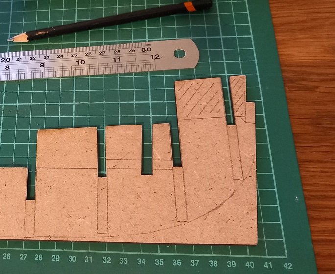
I'm finding out that walnut is as tough as... nuts.... I wish I has a scroll saw, but micro saw and Perma-Grit 'fine' sanding collection will see me through for the moment. The sawdust will be saved to make walnut filler if and when required, good job to as I'm making loads of it. I must also say (if I may) that the fine sanding tools are a joy to use and come in a selection of shapes. I will have to be careful when sanding bevels as the walnut is much harder than the MDF (and of course balsa) but with the MDF being 5mm thick it is very strong. I could have used the MDF frame 12 of course but just love the smell of cut walnut! Avast me hearties!
- 29 replies
-
- 3
-
-
- Fly
- Victory Models
- (and 1 more)
-
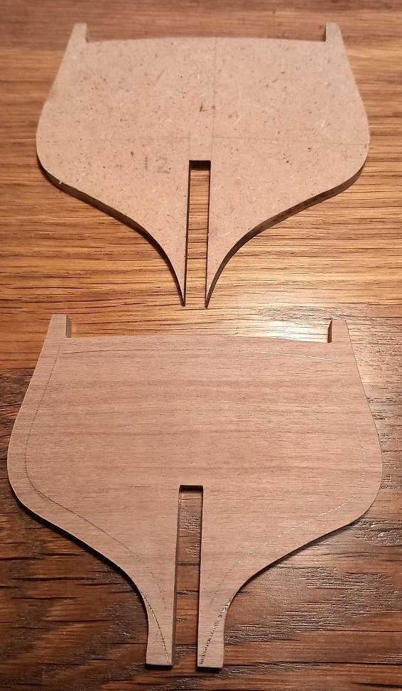
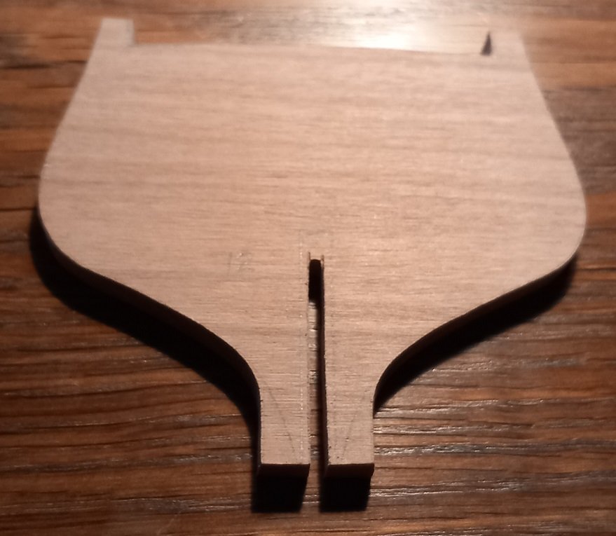
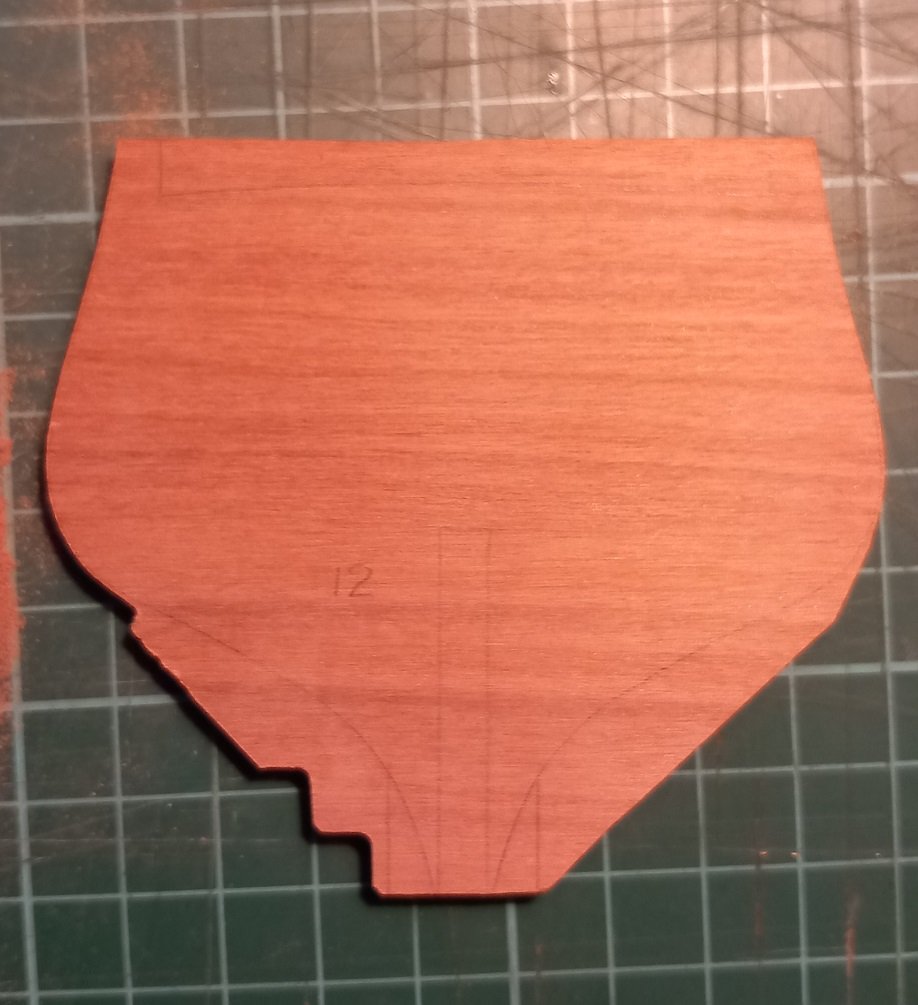
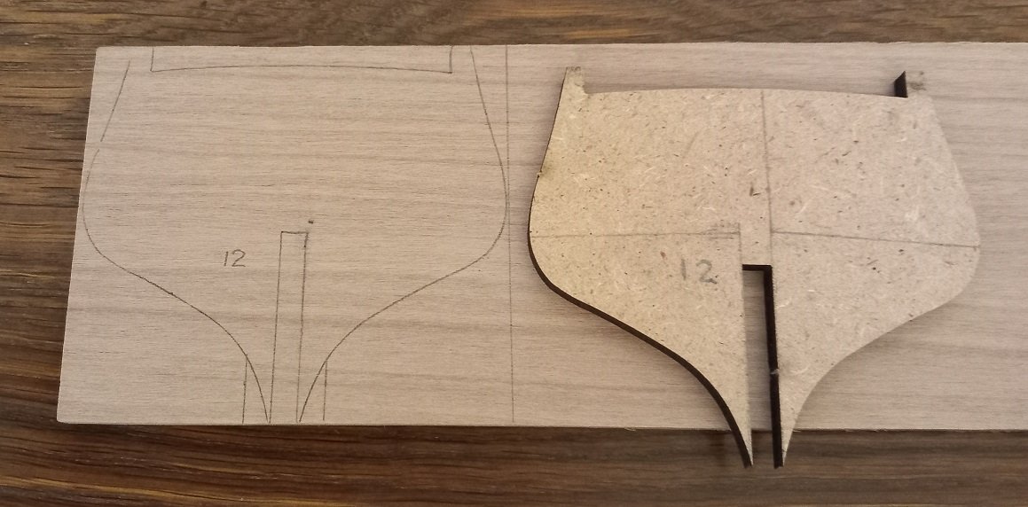
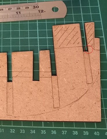
I have some 6mm walnut sheet which will be used to fashion a new frame 12. I would have preferred to have the grain running vertically but the sheet isn't wide enough so I will be leaving a 5mm strip where the frame meets the keel piece. This will be sanded back once the frame is glued to the keel and blocking added between frames to (hopefully) prevent any breaks Once the outline is cut out I will mark the area inside the frame to be removed. To accommodate the extra 1mm width of the walnut a small amount of the keel slot will be widened, shown by the red circle. Now where did I put that micro saw...... Avast me hearties!
- 29 replies
-
- 3
-
-
- Fly
- Victory Models
- (and 1 more)
-
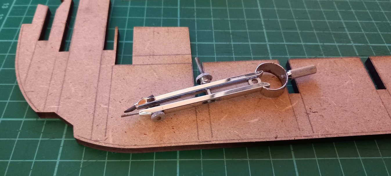
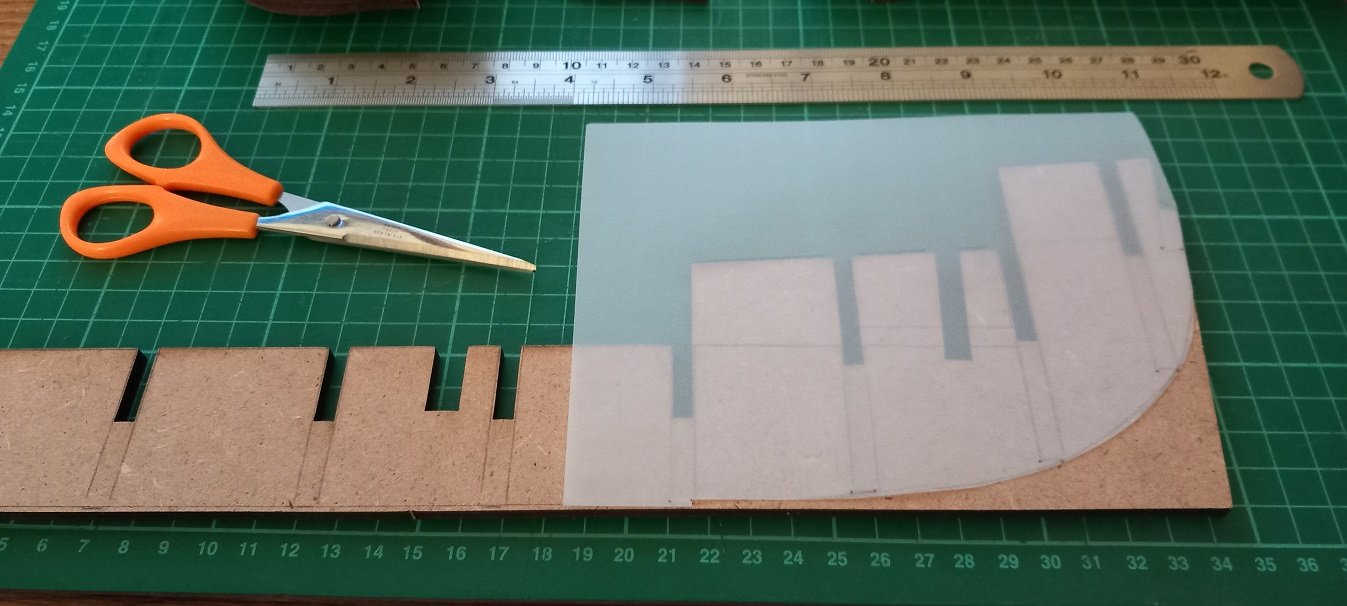
SpyGlass, I have the 2 piece ply deck and haven't closely looked at the castings yet. I trial fitted all the decks and they fit very well with only a little 'tightness' where the two pieces meet around the stern. Easily remedied with light sanding of the frame notches. So I marked the keel with all bulkhead positions and disassembled. I then took my old (we are talking 1960's) drawing set and used a compass to mark 1.5mm above the keel for the rabbet line. Notice the compass pin is extended to allow it to drag along the keel. The bearding line was created with a piece of tracing paper placed over the stern and a line drawn followed by cutting of the tracing paper. The bearding line can then be traced around (the tracing paper!) on both sides ensuring accuracy. Note the 1.5mm notch for the rabbet at the bottom. And finally the stern keel has marked for removal the area which would protrude into the captains cabin. Next I will ponder a new frame 12. Where did I put me Walnuts? Avast me hearties!
- 29 replies
-
- 3
-
-
- Fly
- Victory Models
- (and 1 more)
