

ERS Rich
-
Posts
660 -
Joined
-
Last visited
Content Type
Profiles
Forums
Gallery
Events
Posts posted by ERS Rich
-
-
15 hours ago, Rick310 said:
Really nice!! Great description of your technique!!
Thanks Rick, hope to show simple ways to do the work. And for the next project, have a reference to refer to, when I forget how I did it….
Have a good weekend.
- mtaylor, Keith Black, Canute and 1 other
-
 4
4
-
Welcome aboard! Always open to answer a question.
- Keith Black and mtaylor
-
2
-
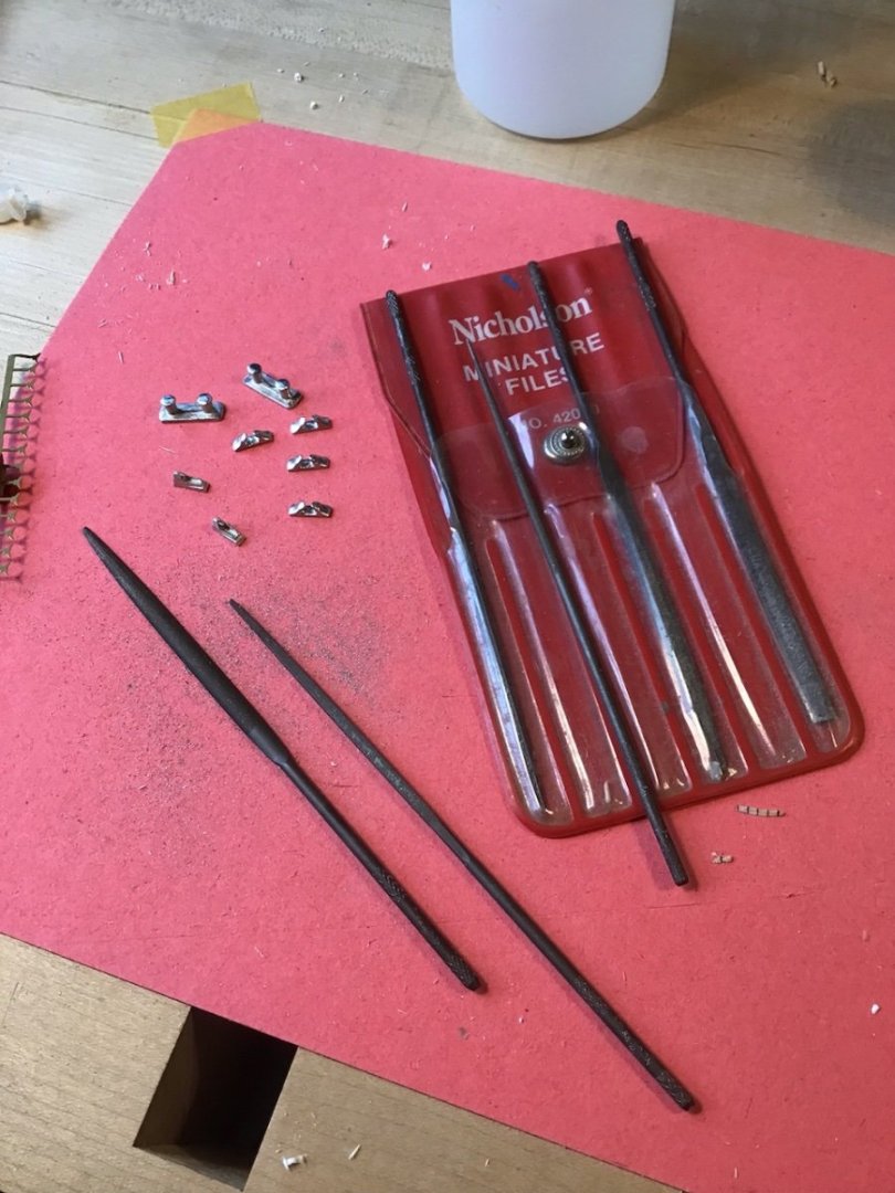
Small files work well for precision and yield a bright smooth finish. Thinned Mr Primer, brushed on to prime.

-
Progress Photos
Not as much time for the shop the past few weeks - spring projects, trouble with the house boiler, amongst other things. Should have more time for the shop in the weeks ahead. Hoping to wrap this up by the end of May.
Working on completing the mid and aft superstructures. Same processes used for the fore superstructure.
And beginning to build the sub assemblies for the run up to final assembly. Ahead is the PE for the catwalks, cranes, etc.
Here is the mid superstructure in the tail vise, with a plastic piece on the left acting as a caul, to apply pressure on the curved forward end plywood skin.

Next is the mid superstructure with plywood installation around the perimeter complete.
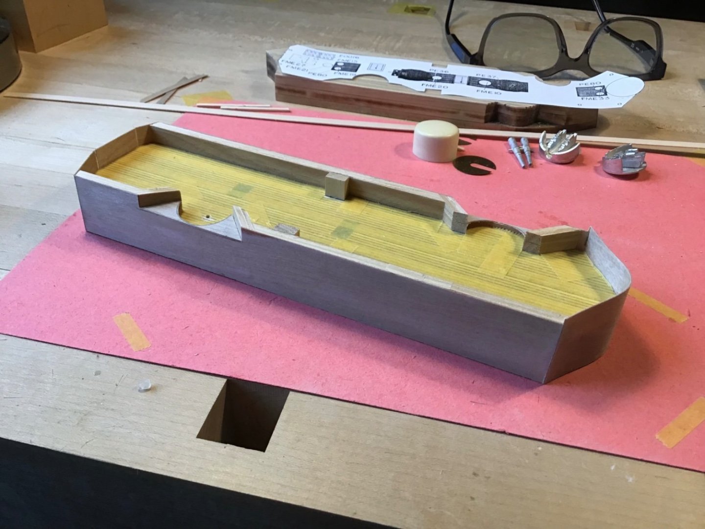
This picture shows applying the 3/16” half round. A spacer block is used to position the middle piece.

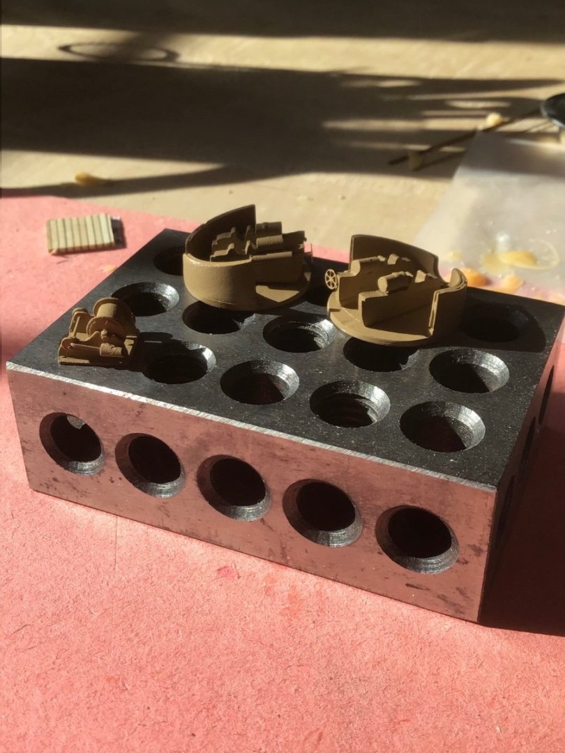
A few of the sub assemblies - 6 pounder gun tubs note the tiny hand wheels, and the deck winch.
Mid and aft superstructures dry fitted.
Have a great weekend!
- coxswain, Canute, Keith Black and 5 others
-
8
-
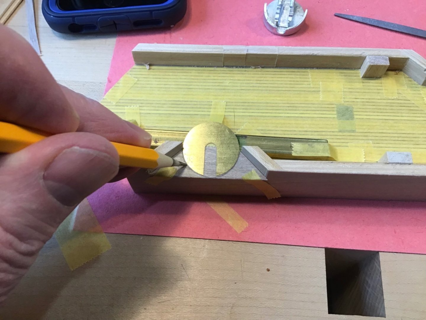
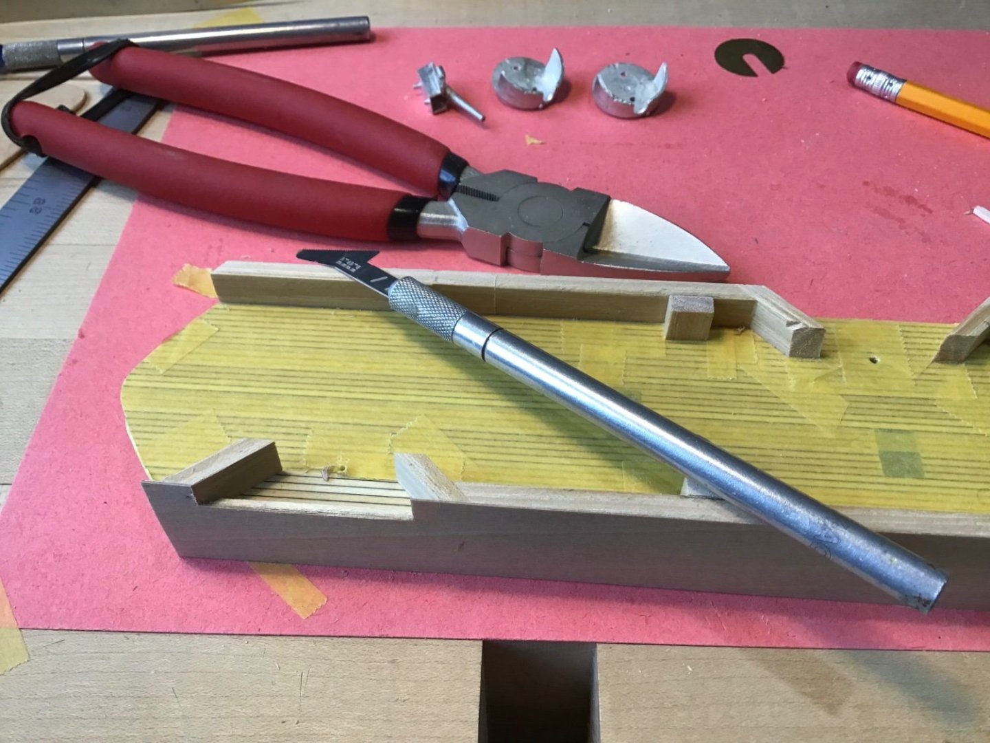
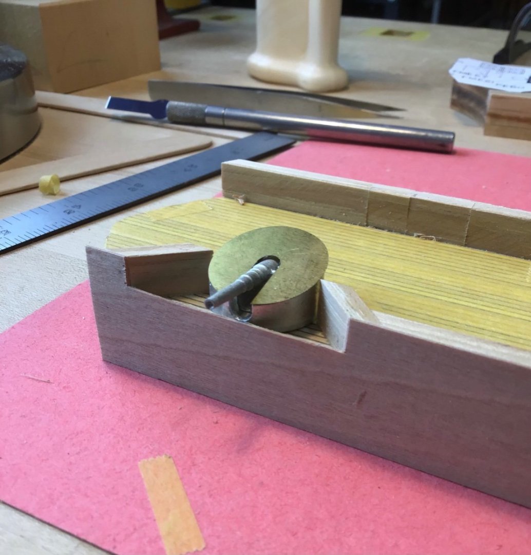
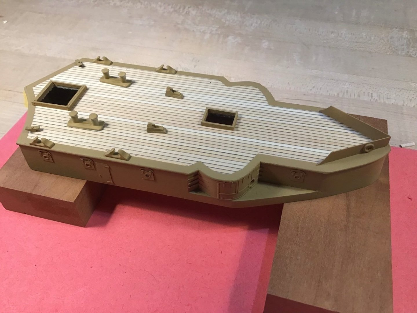
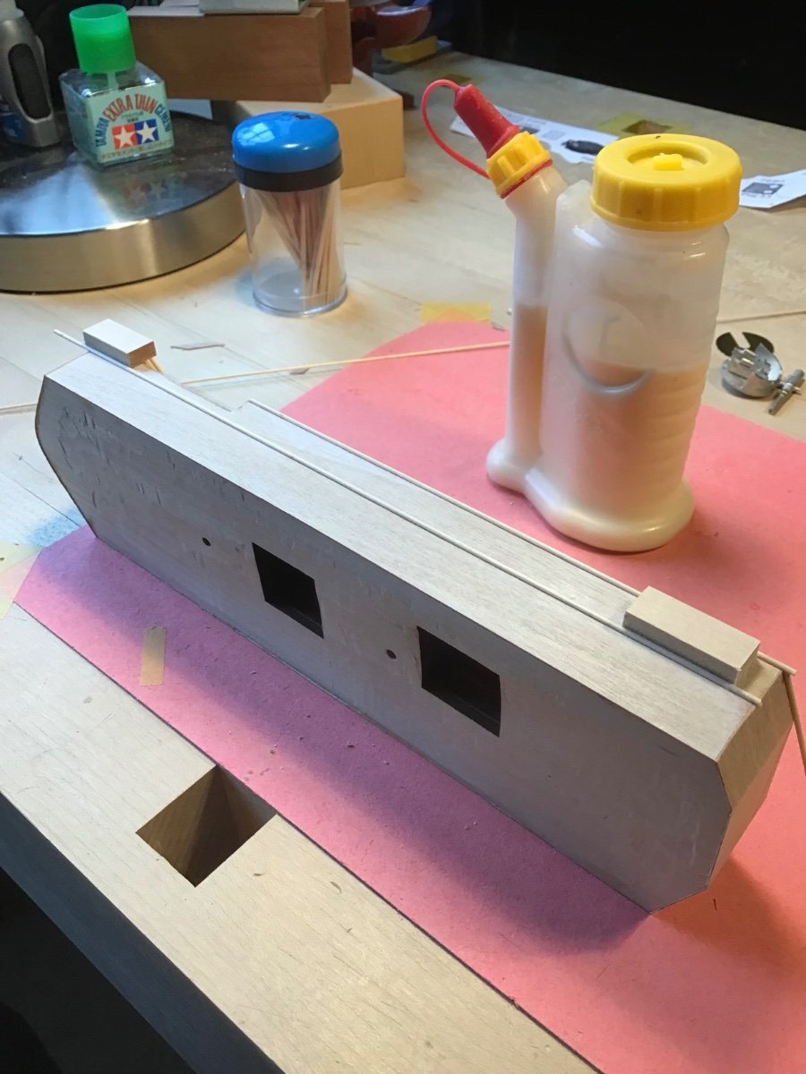
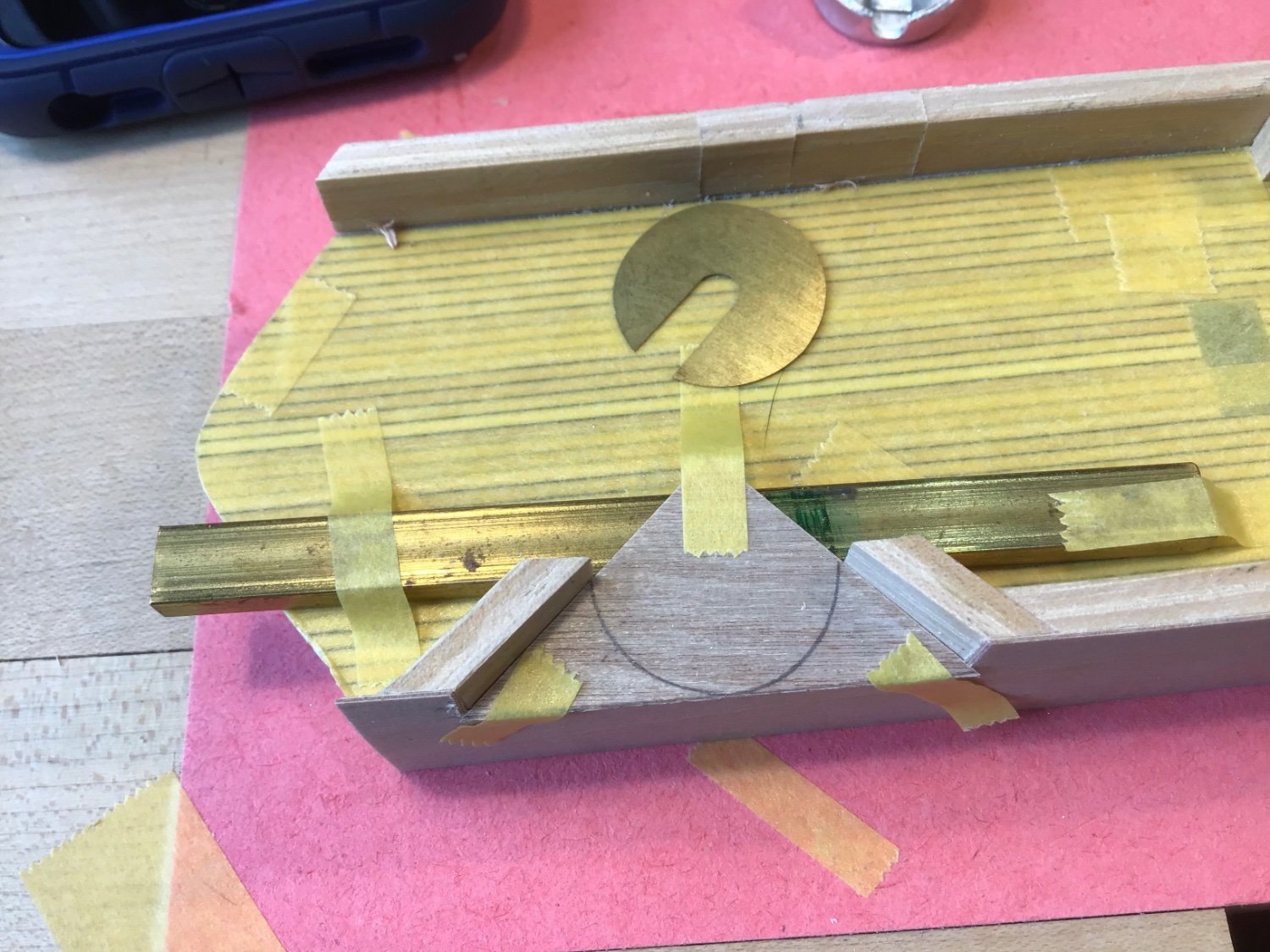
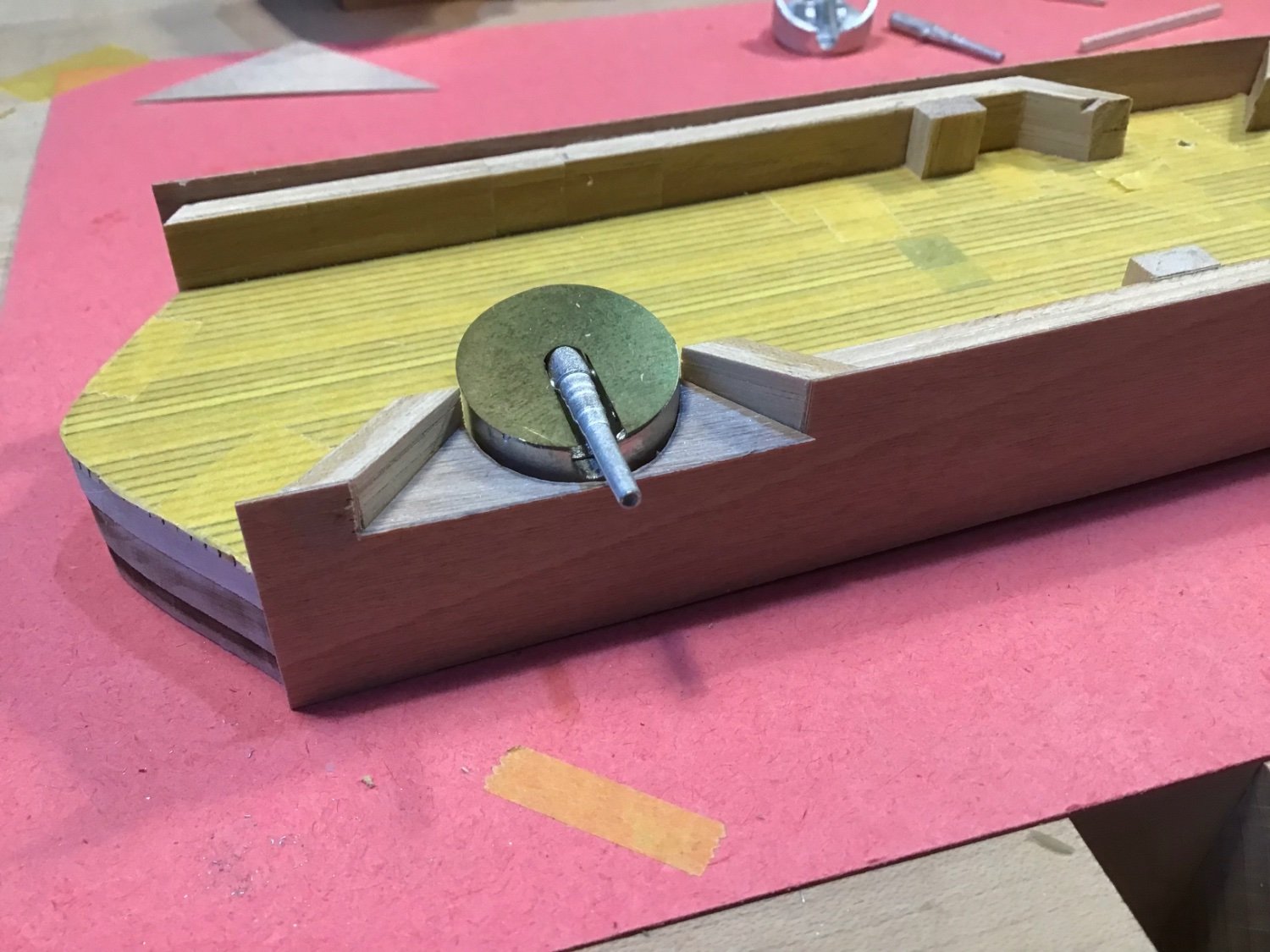
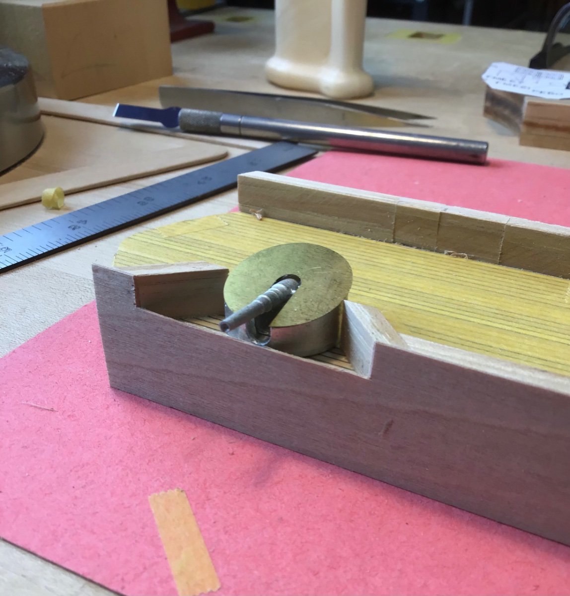
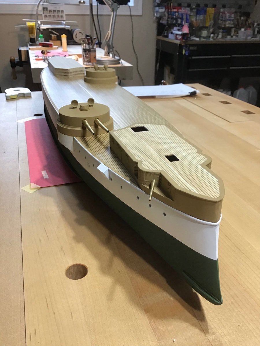
6” Turret Splinter Shield
Spent time reviewing the instructions and plan to understand how to make this piece. Seems harder at first than it really is.Starting with the fore/aft width of the opening, cut a piece of material slightly longer on the paper cutter and cut a 45 degree angle at each end. The outboard sill is 3/32” high, the rise of the shield outboard to inboard is 1/16”, so the inboard height is 5/32”, the brass bar is 5/32” (part of a Standard set from Micro Mark). Marked a line underneath the shield along the edge of the bulwark, and trimmed the piece.

Next secured the pieces with tape and used the turret cover as a template to mark the opening in the splinter shield.

Next drilled a series of relief holes and cutout the waste. Started with larger sweep gouge.
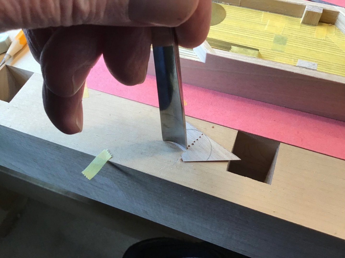
Used a the smaller gouge to approach the line, and a fine file to meet the line.
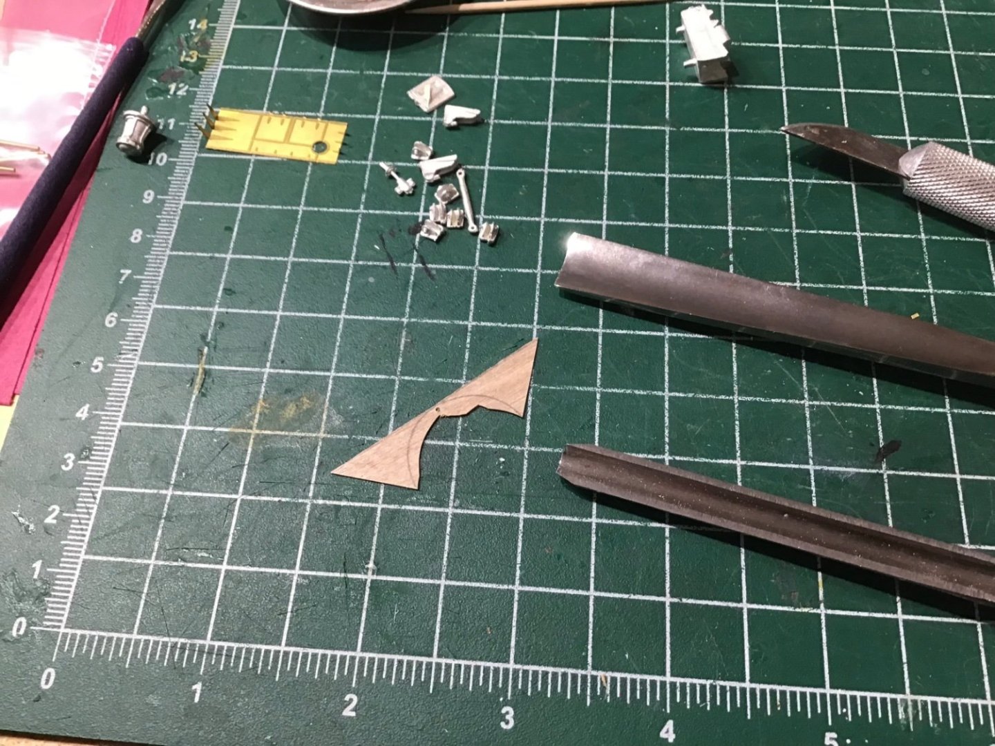
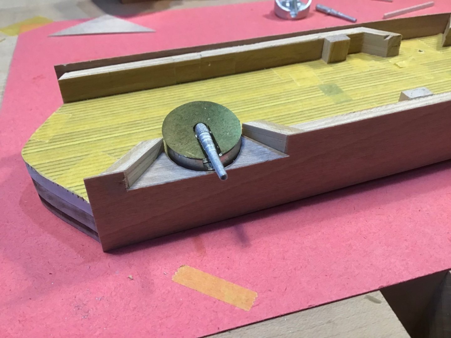
The shield installed.
- Rick310, Keith Black, mtaylor and 6 others
-
9
-
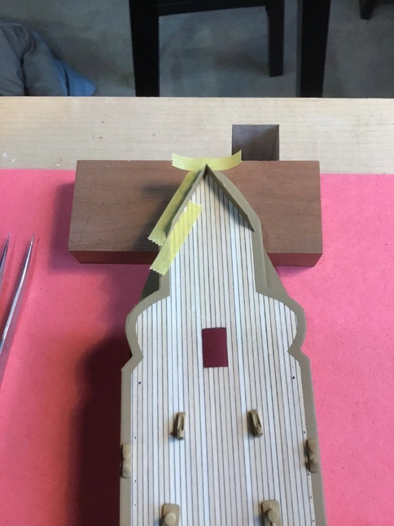
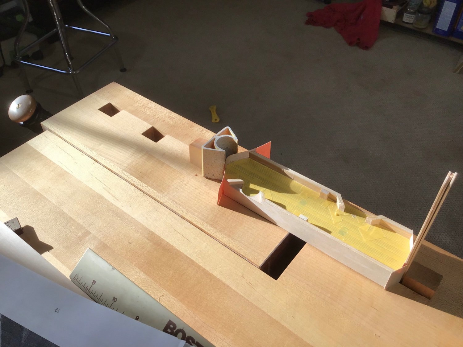
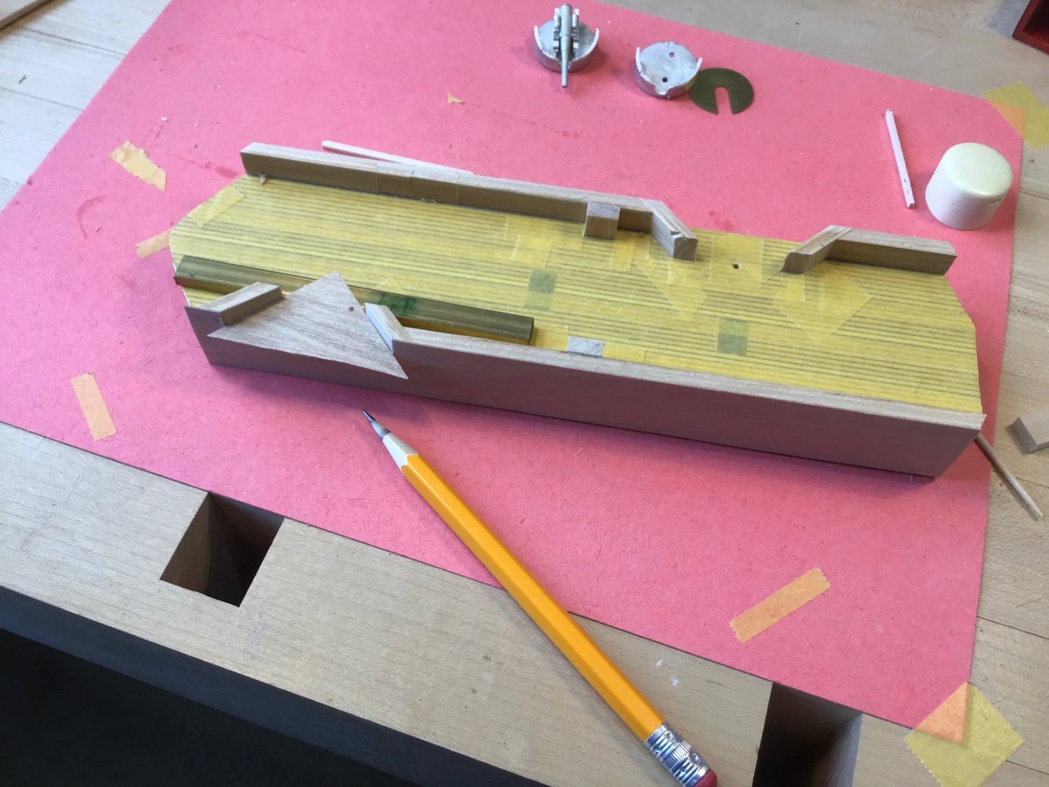
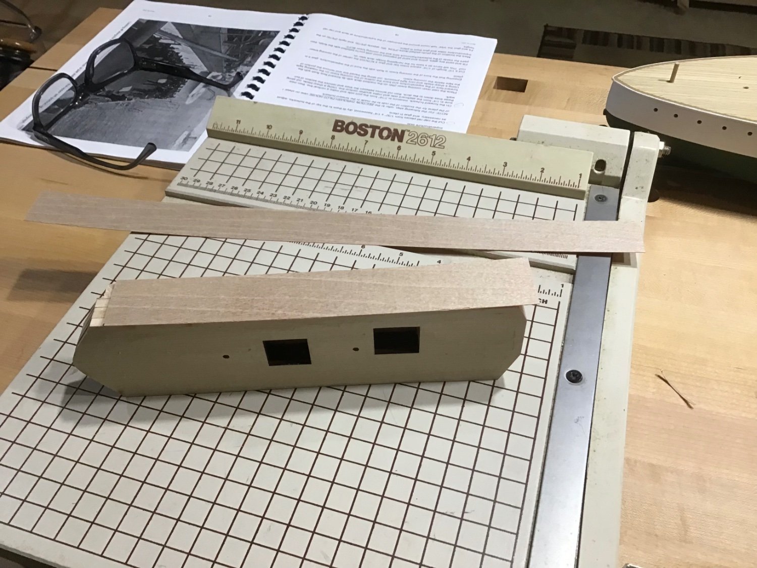
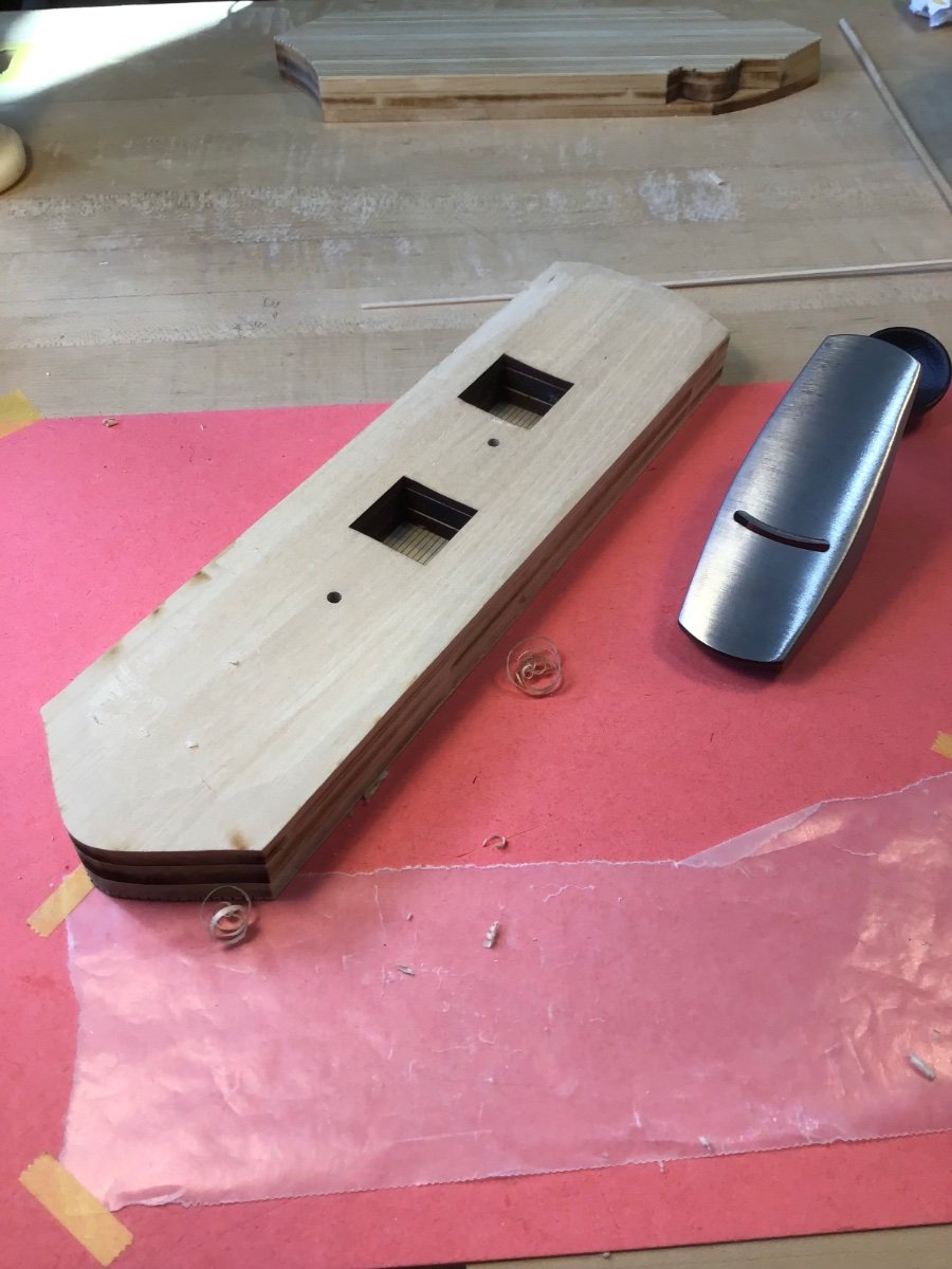
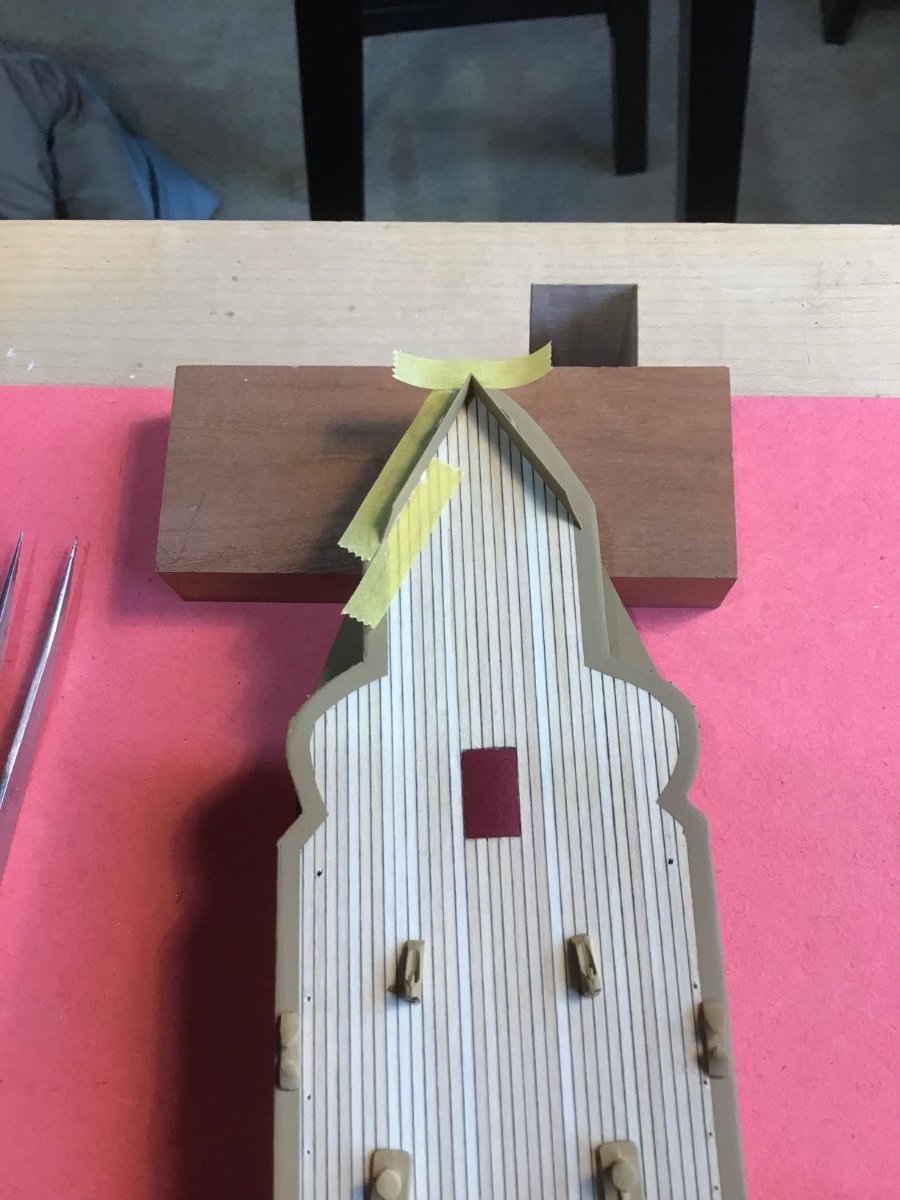
Midships Superstructure - Part 1
First made a photocopy of plan for a template.
Reckoned that the position of the gun turrets drives the assembly so fitted the turrets first then built the hammock lockers. Cut stock with a Byrnes table saw.
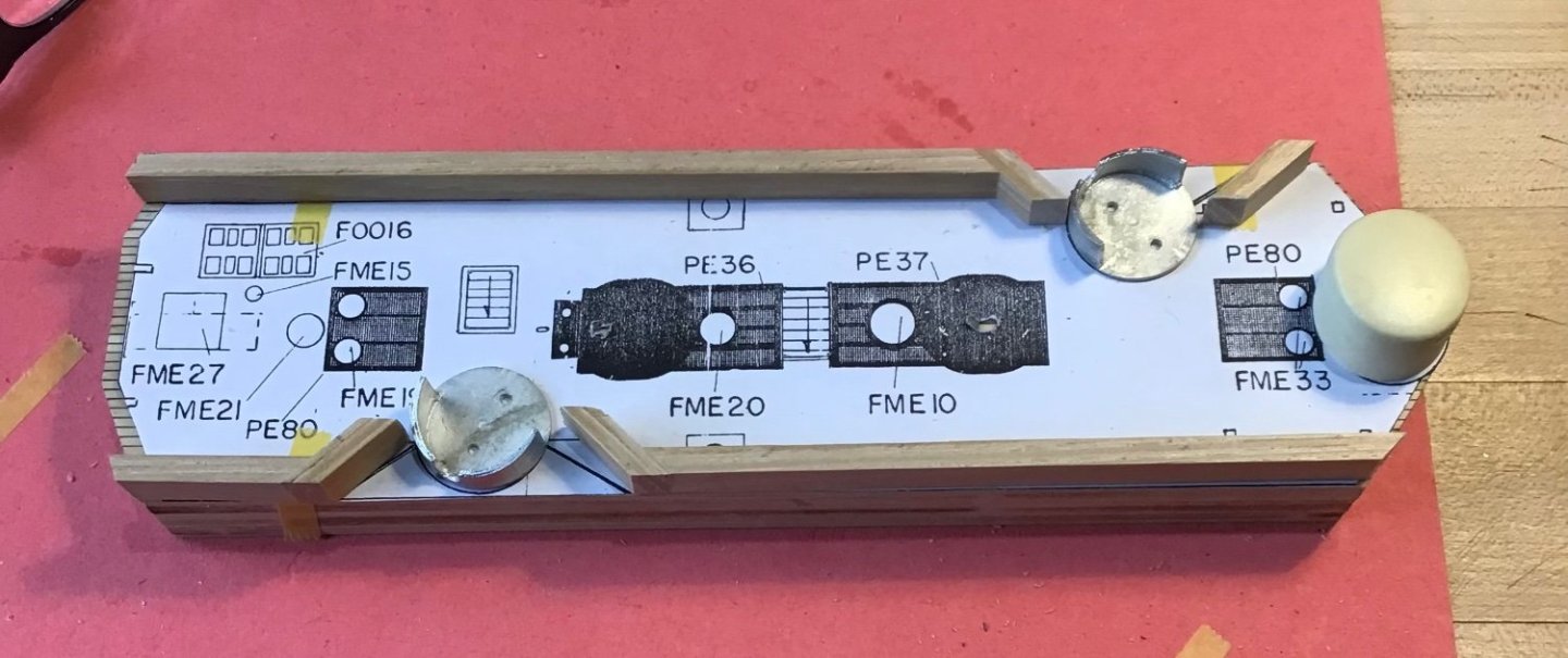
Rough trimmed the plywood pieces for the bulkhead sides with a papercutter. Then glued to block.

Trimmed the bulkhead bottom and top flush. Used a 5/32” wide piece of stock as a temporary sill for the horizontal bulkhead cut In front of the 6” turret.
Trimmed with Tamiya precision saw in an X-Acto holder. The red handle tool is a flush cutter, typically used to cut veneer or plastic board edge banding, sourced from Fastcap.
Turret dry fitted.
- GrandpaPhil, Prowler901, Canute and 3 others
-
6
-
1 hour ago, Rick310 said:
Nice build!! Great job with the airbrush!!
Thanks Rick, it did take awhile to get the hang of it….
- mtaylor, Canute and Keith Black
-
3
-
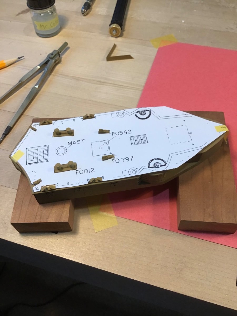
Middle Superstructure Fitting
Have to fit the superstructure to the deck camber.
Started by planing the bottom with a plane with a convex sole. Plane sourced from Veritas woodworking. Planed to as close to the edge without going over.

Next is to scribe the sides so they fully contact the deck. Here I used a pencil to mark where the the part touches the deck. Then the convex plane was used to carefully remove marked wood, planing along the edge and from outside to inside.
- Canute, Prowler901, Ryland Craze and 6 others
-
9
-
-
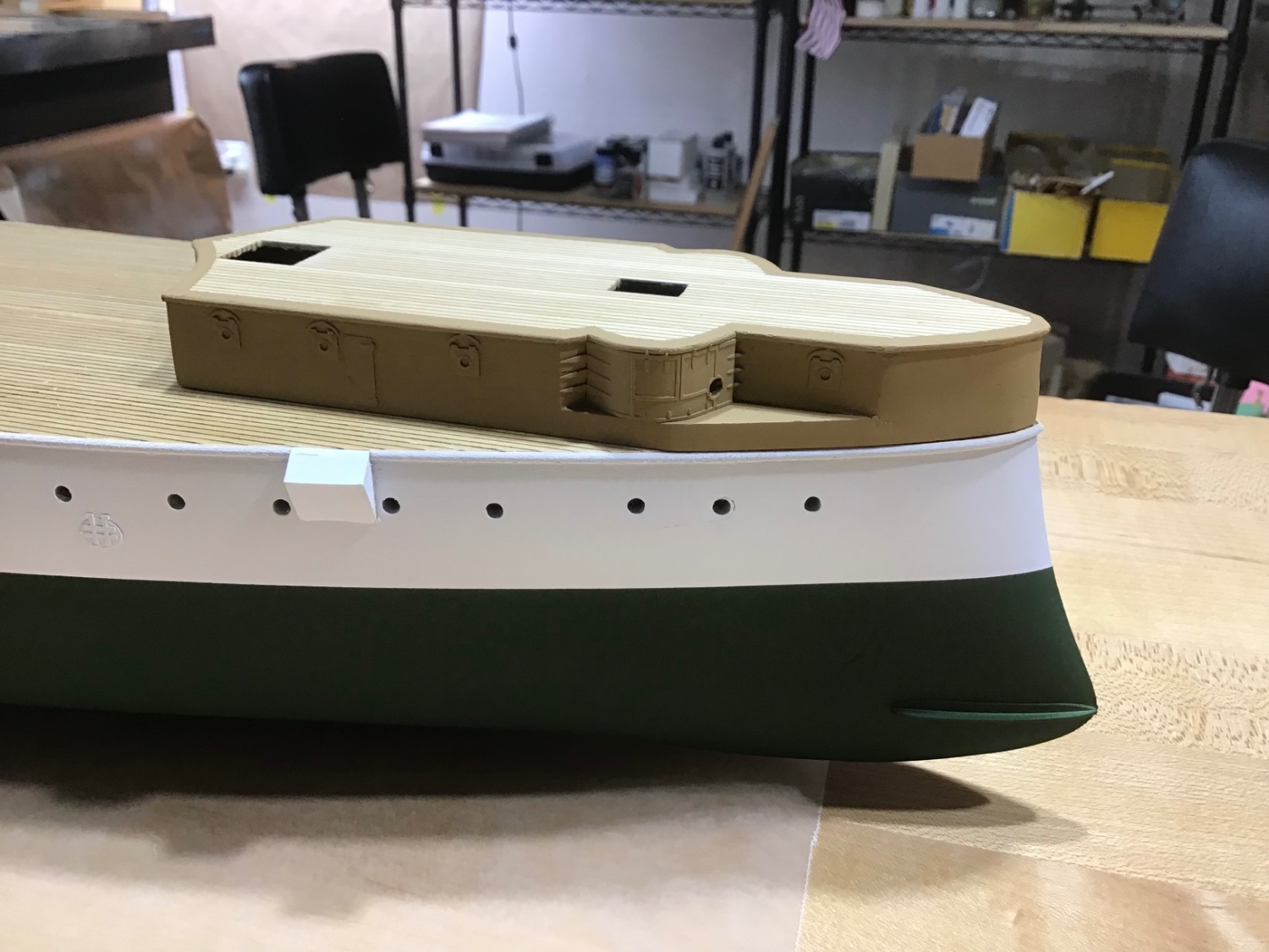
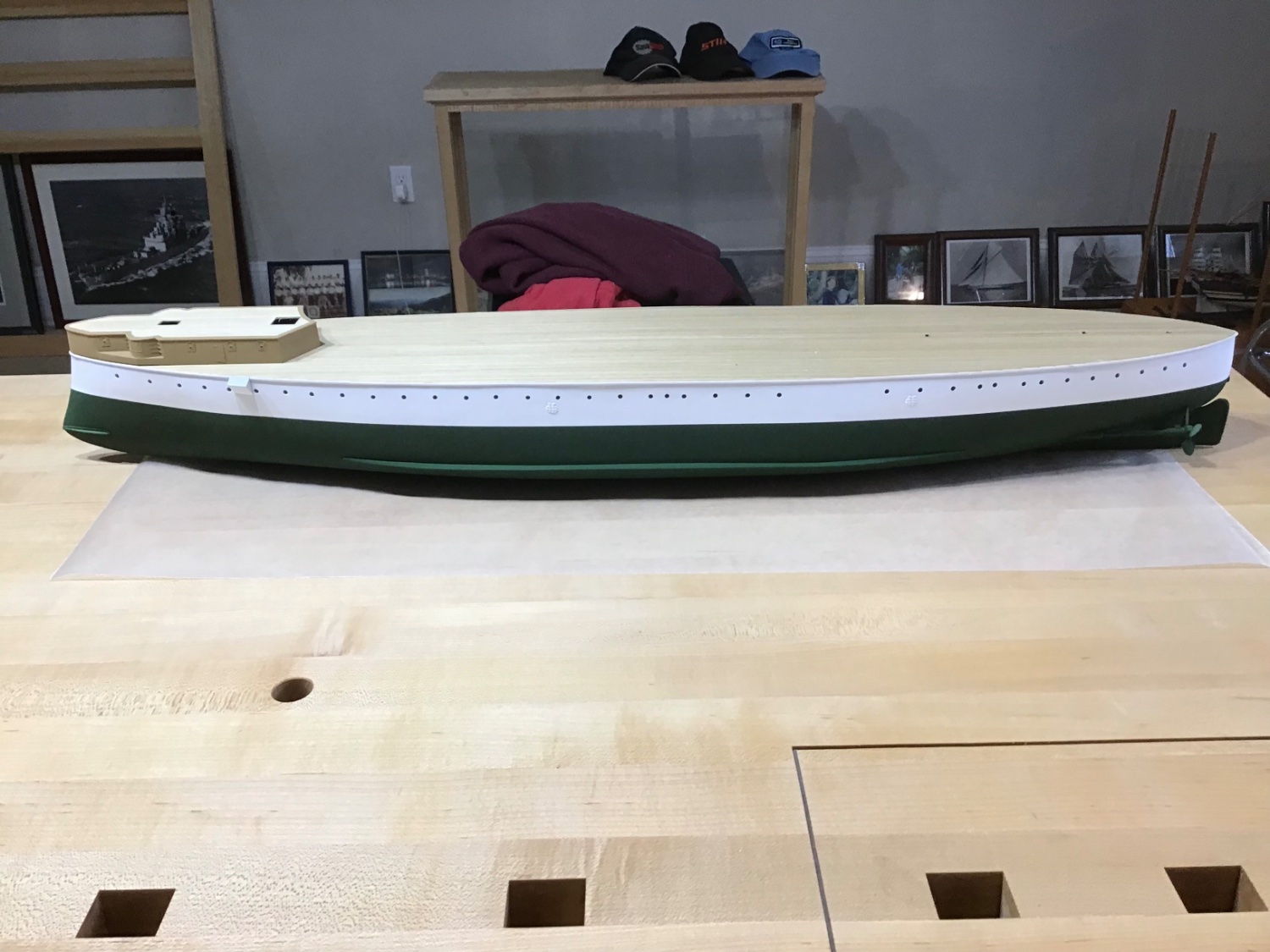
Finishing the Forward Superstructure
The completion of these steps bring us to page 16 of the instruction book.
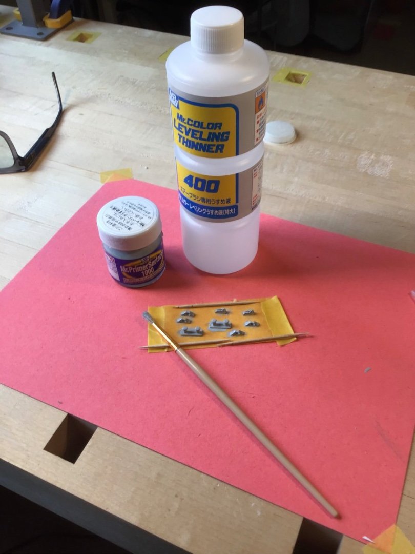
Filed the parting lines from the metal fittings. File set purchased at Home Depot.
Next primed the fittings with Mr Primer, thinned with Mr. Color; then painted with XF-26.
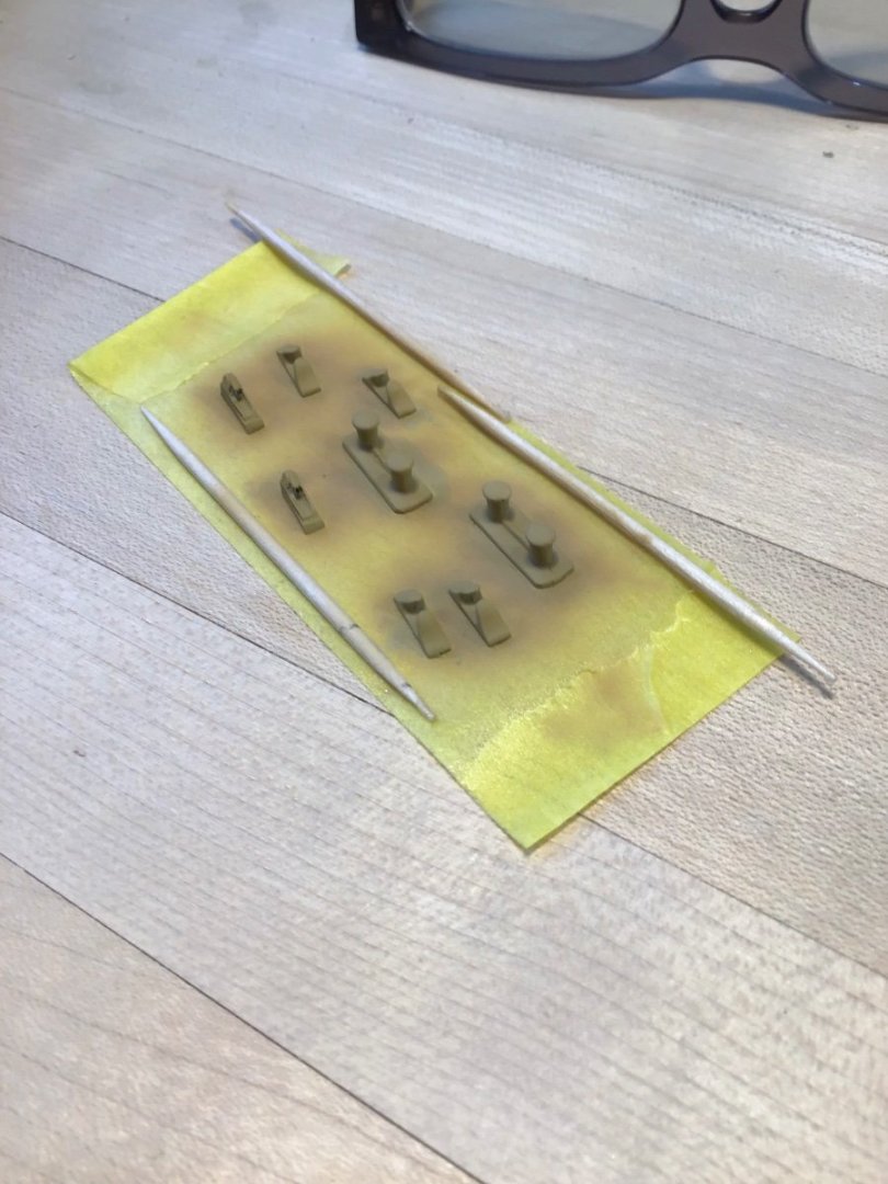
Next made a photocopy of the deck, cutout the openings for the fittings, and installed them. And removed the template.

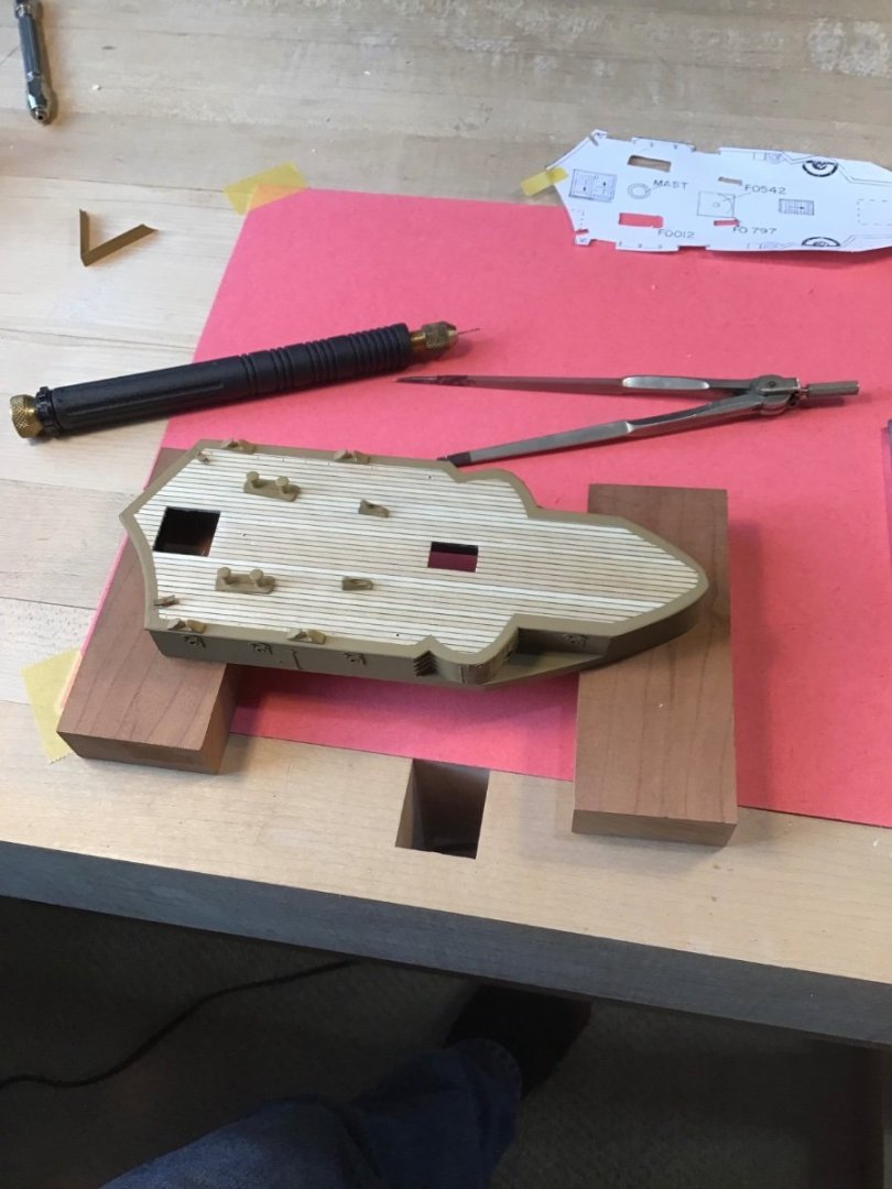
Next installed the bow break. The challenge here is to get adhesive on the thin edge of the styrene without a mess. So dry fitted the break, applied tape on the deck along the edges, removed the break, applied adhesive to the deck, reinstalled the break, slowly removed the tape before the adhesive dried.
Finally installed the hatch coamings, and cleats. Cleats by Syren Ship Model Company
- ccoyle, GrandpaPhil, Haliburton and 9 others
-
11
-
 1
1
-
Hello and welcome to the forum. I’m always available to answer a question.
Please take a look at a build log to learn the ropes. Logs can be accessed from the home page.
There is a link to my Constitution log below my signature.
As for tools, super special tools aren’t needed. Suggest a chisel or two, a set of small files, and a block plane for plank tapering.
Learning the techniques of woodworking is important. How to sharpen and use a chisel, understanding wood grain, how to work wood with a plane and files. Plenty of YouTube videos out there. Or a basic woodworking course.
Finally grab a book.. In my opinion the best book for beginning is “Ship Modeling Simplified”. Shows all the major steps, how to do it, and a glossary - the terminology is half the battle.
Good luck on your shipbuilding journey.
-
Good stuff, thanks for posting
-
Checkout this build post:
- Knocklouder and mtaylor
-
2
-
Hello Rudy,
Not sure how long the plank being installed is.
Working with short planks is easiest. My preference is a plank that spans four bulkheads. And Titebond wood glue with Locktite superglue.
Apply Titebond with a toothpick along one edge, set the plank aside, then a dot of super glue on each bulkhead. Place the plank and push the edge with Titebond against its neighbor. Apply pressure at each bulkhead until the superglue sets. The superglue will fix the plank in place, while the Titebond dries.
Use a scrap plank to scape any squeeze out.
Checkout my Constitution Hull build log for more planking examples- link in my signature below.
Cheers
- Knocklouder and mtaylor
-
2
-
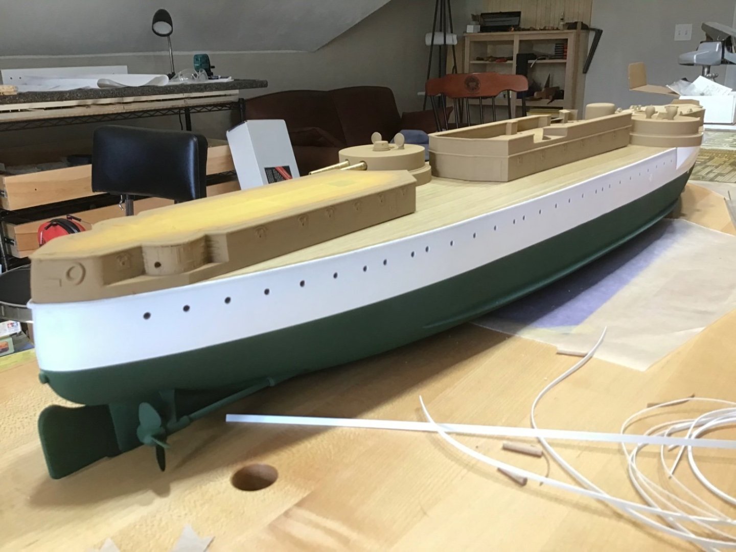
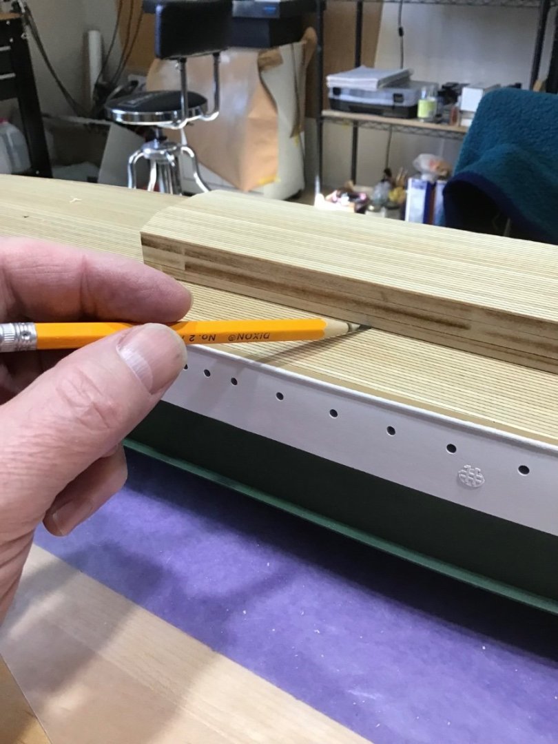
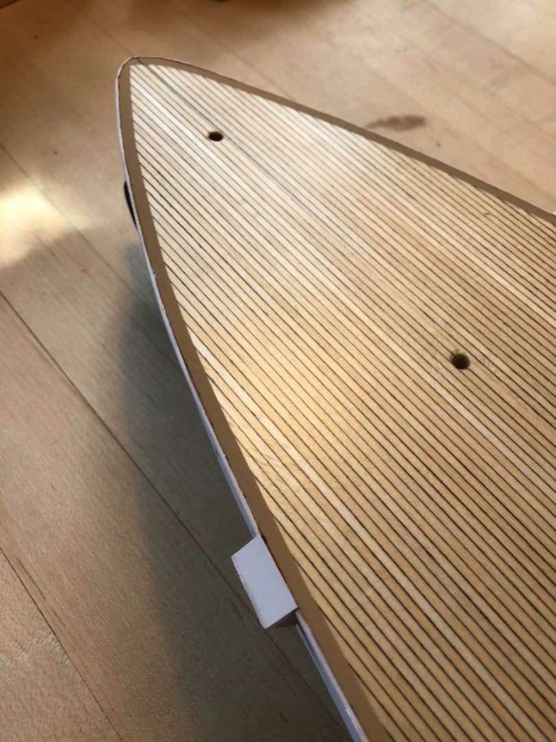
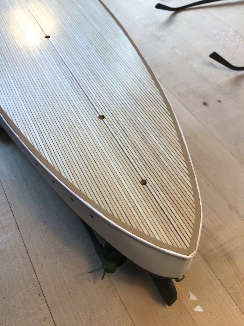
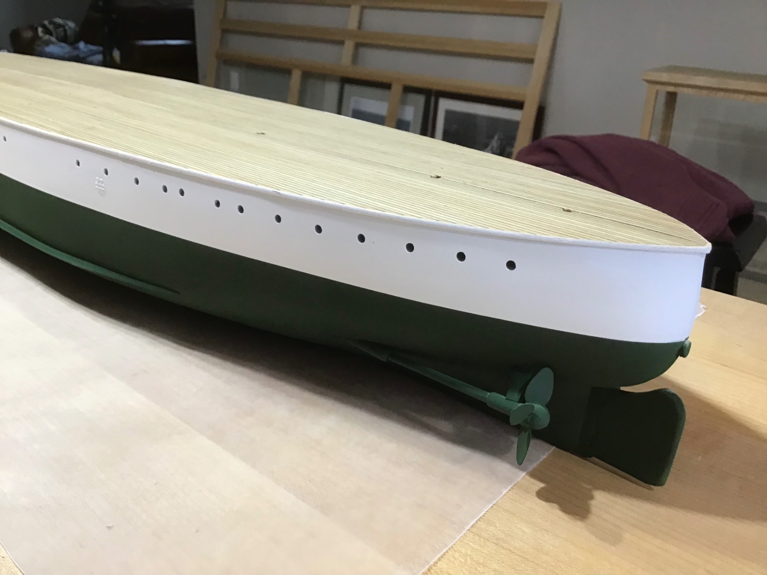
Finishing the Hull
Last steps to finishing the Hull are drilling the holes for the deck stanchions and turnbuckle eyebolts; and anchor bill top plates.
This brings us to the top of page 14 of the instruction book.
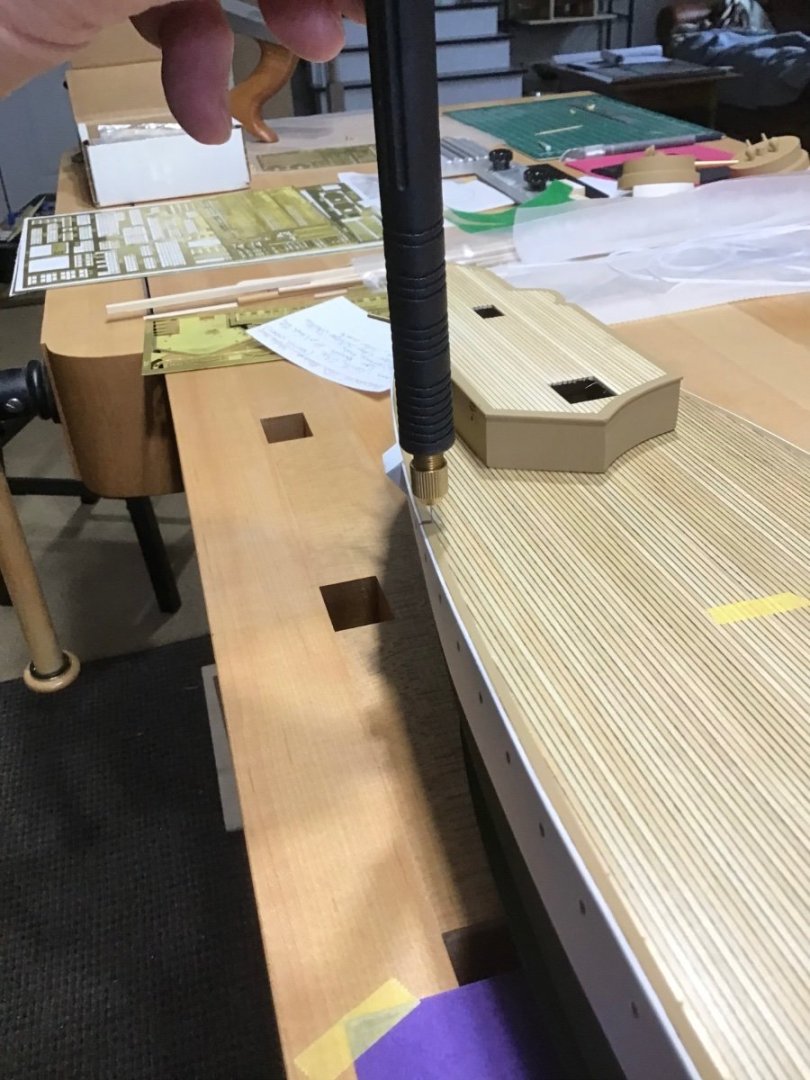
First photo shows drilling a hole with an Amati pin vise with #76 drill bit. Stanchion hole locations were marked off using plan sheet 2, starting from the forward superstructure and working aft.
Second photo shows painted anchor bill plates in place.
-
Welcome aboard Senior Chief; always open to answering any questions shipmate!
- Edwardkenway, Keith Black, mtaylor and 2 others
-
5
-
-
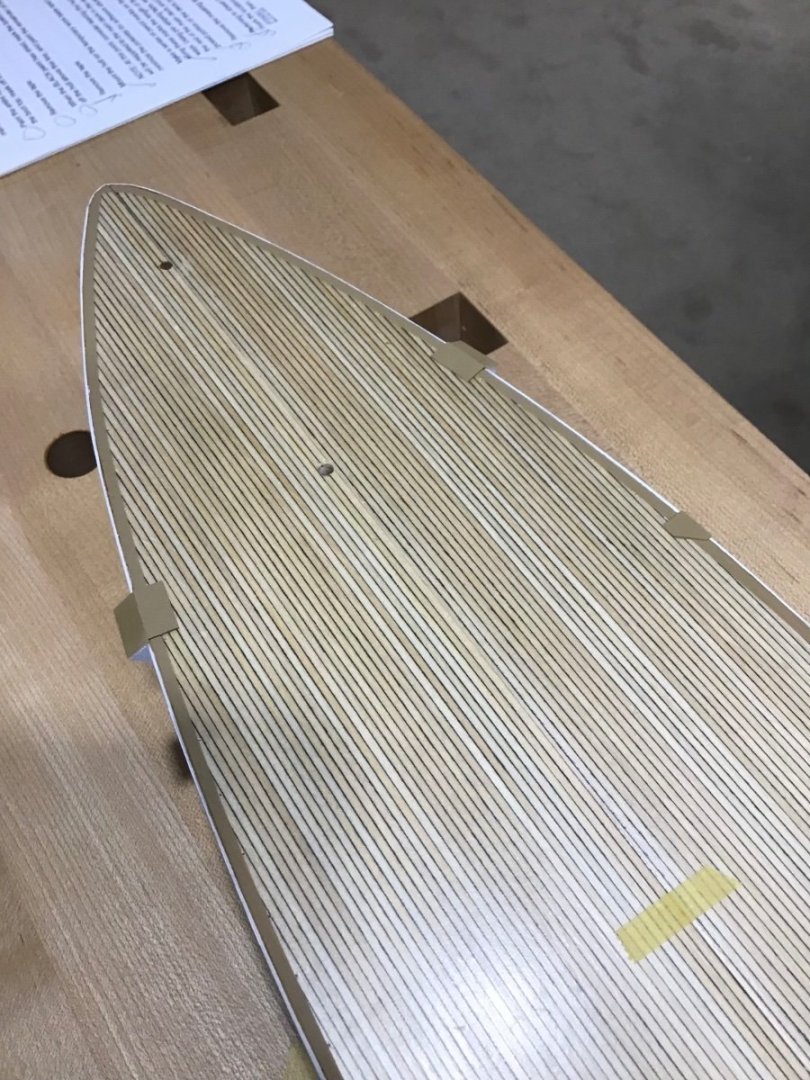
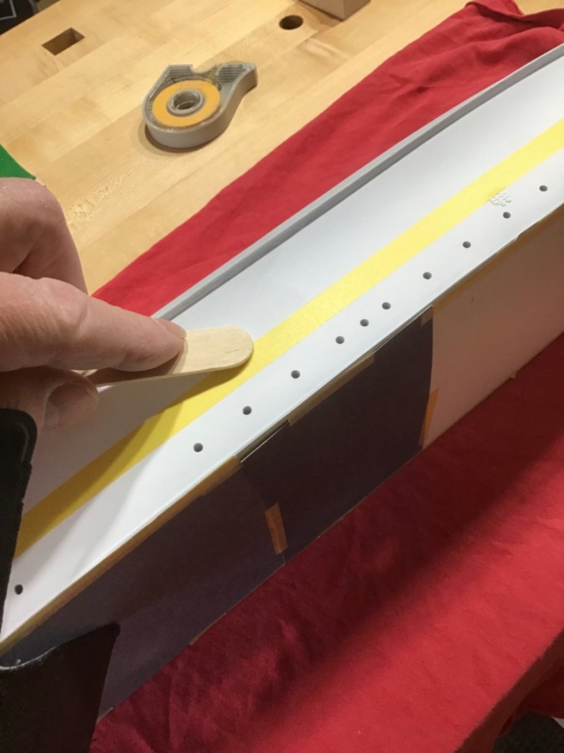
Painting the Waterways
An exercise in masking….
Used Tamiya 3mm tape as a spacer at the edge half round hull trim, then masked along its inside edge, and construction paper to mask the remaining deck.
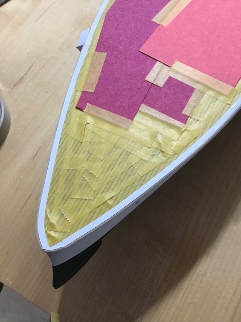
Then removed the white tape. Not shown is I masked the top edge of the half round.
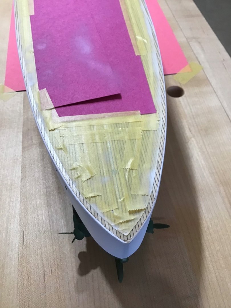
Then painted the waterway Tamiya Desert Yellow XF-26, with Paasche Talon #2 tip. Next masked over the waterway and painted the top edge of the half-round white.

-
-
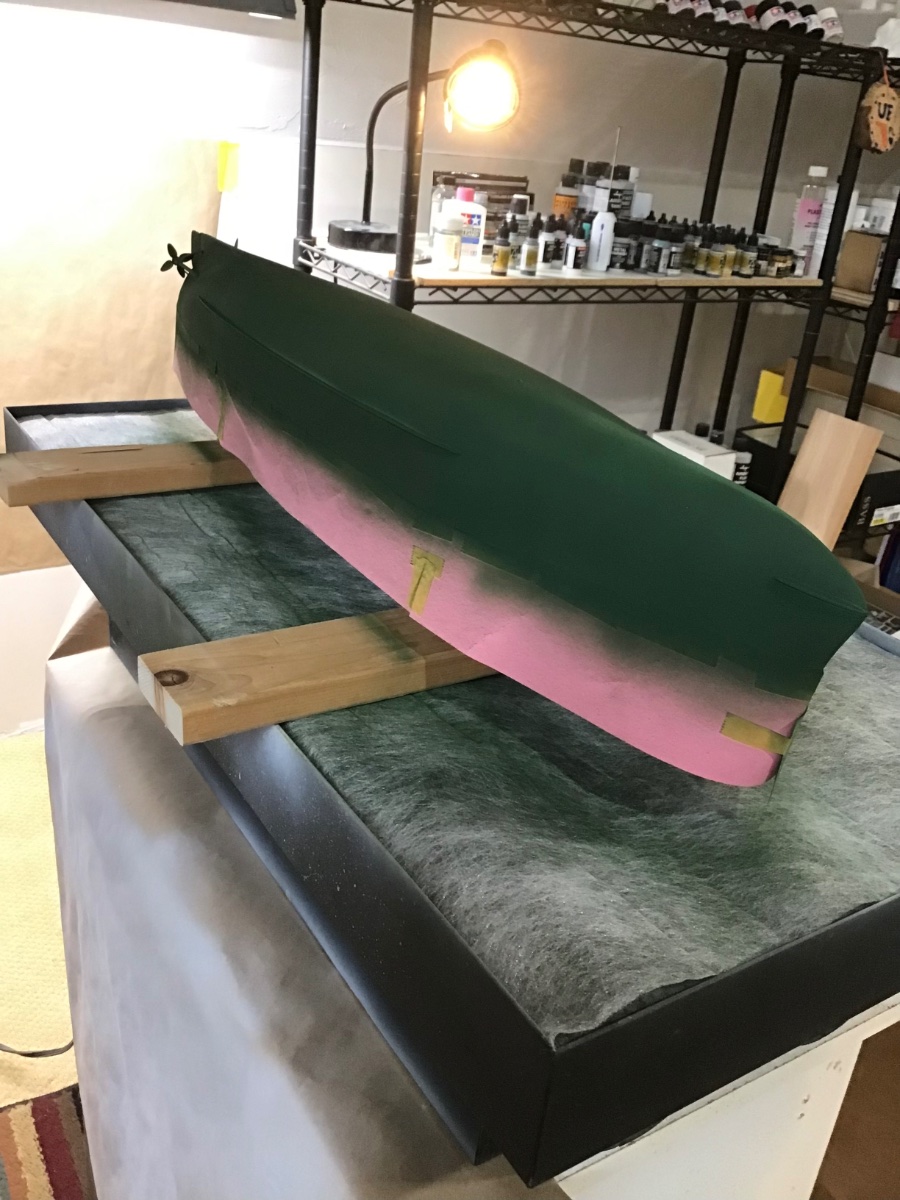
Hull Painting - Dark Green
Leveled the model and marked the waterline.
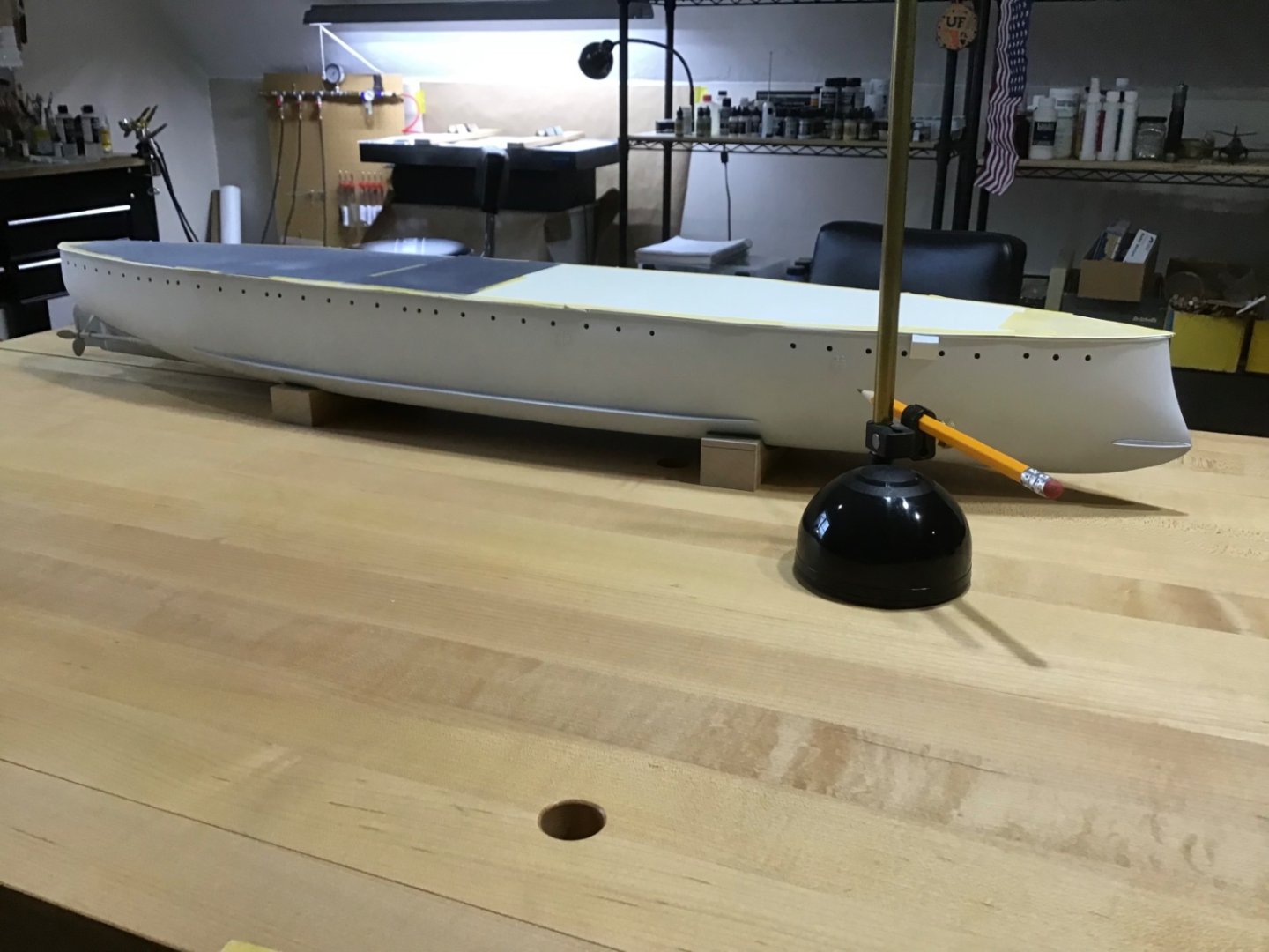
Set the model on its side on a red rag, and applied a single continuous piece of Tamiya masking tape along the marks. Then lightly burnished the tape with a wooden tongue depressor.
Finally used construction paper to make a skirt around the model. Applied Tamiya XF-26 Deep Green with the Iwata RG-3 mini sprayer @20#.

- mtaylor, Prowler901, Ryland Craze and 4 others
-
7
-
Welcome! Greetings from Massachusetts, USA.
- Edwardkenway, Dave_E, mtaylor and 1 other
-
4
-
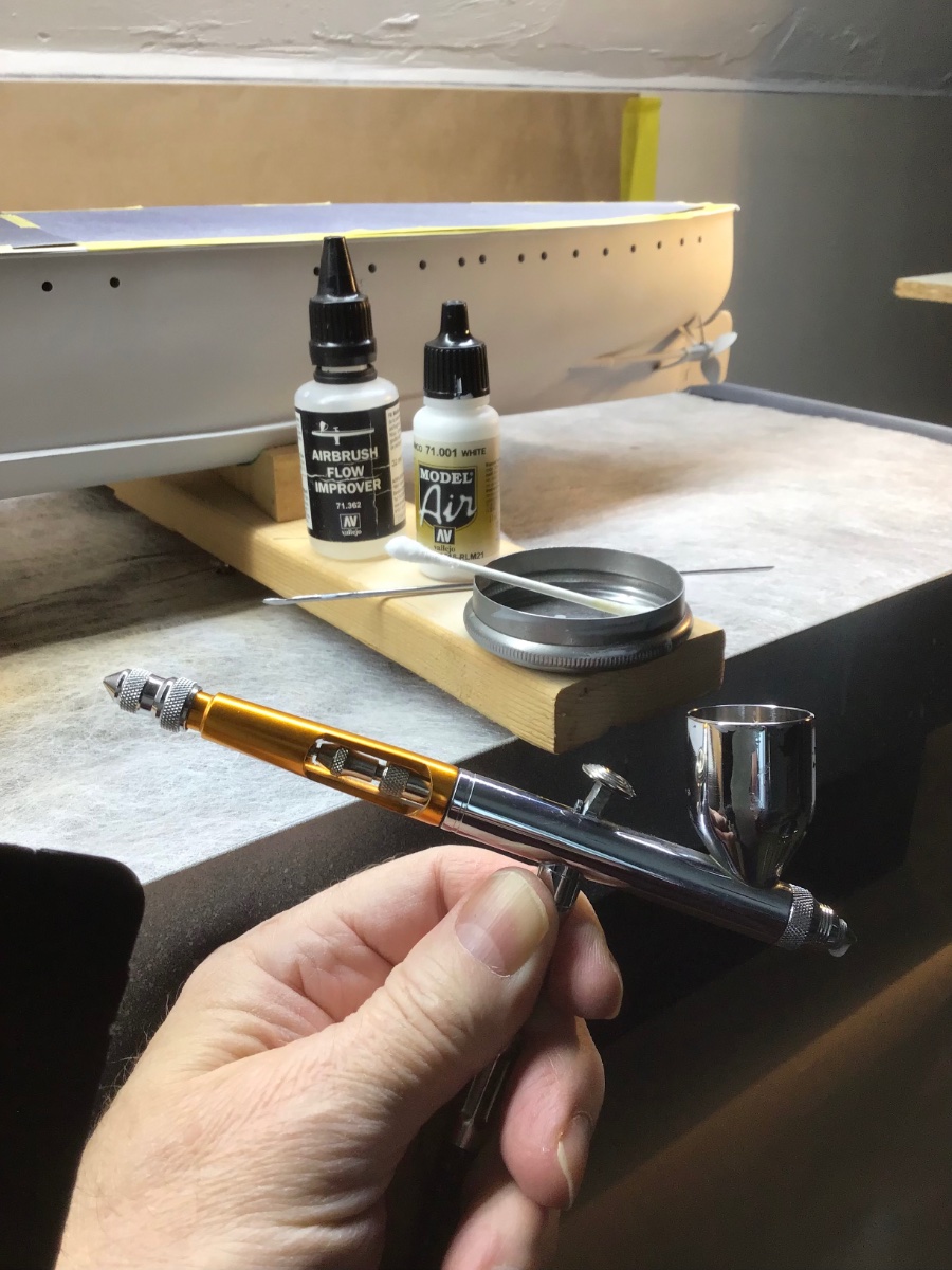
Hull Painting - White
The plan is to paint the hull above the waterline white, and below the waterline dark green; so white first, mark and mask the waterline, then the dark.
Considered Tamiya XF-2 Flat White, decided on Vallejo Air 71.001 White, seemed less intense to me.
Dusted the hull on the table, fans on, with a soft brush.
The setup is Paasche Talon, #3 tip, @22#. Paint applied in coats. Each coat is 50 drops paint, 10 drops flow improver. Starting with empty cup, 1 drop thinner first to flood the nozzle, two drops flow improver, 50 drops paint, 8 drops flow improver. Stir mix in cup well with a stirring stick.
Found this volume of paint to be enough for 1 coat from bow to stern on 1 side. Paint was applied in a circular motion, with the airbrush always moving. Also a q-tip moistened with thinner is at the ready to clean the tip.

-
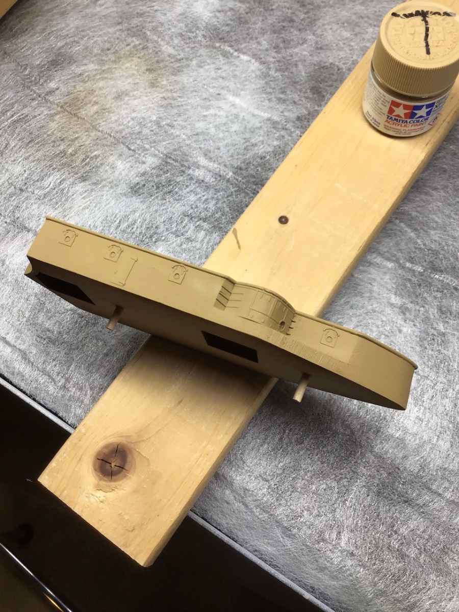
Painting the Forward Superstructure
The top was masked, leaving a 1/8” wide perimeter around the outside edge. 1/8” white pinstripe tape was applied first to the super structure outside edge, to act as a spacer, then the Tamiya masking tape along it’s inside edge.
The bulkheads were sealed with shellac, and the brass primed with Mr. Surfacer primer. Mr. Surfacer works very well. Plan is to prime the remaining PE sheets with Tamiya primer.
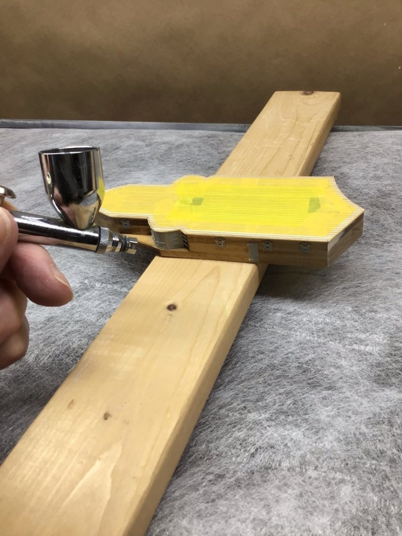
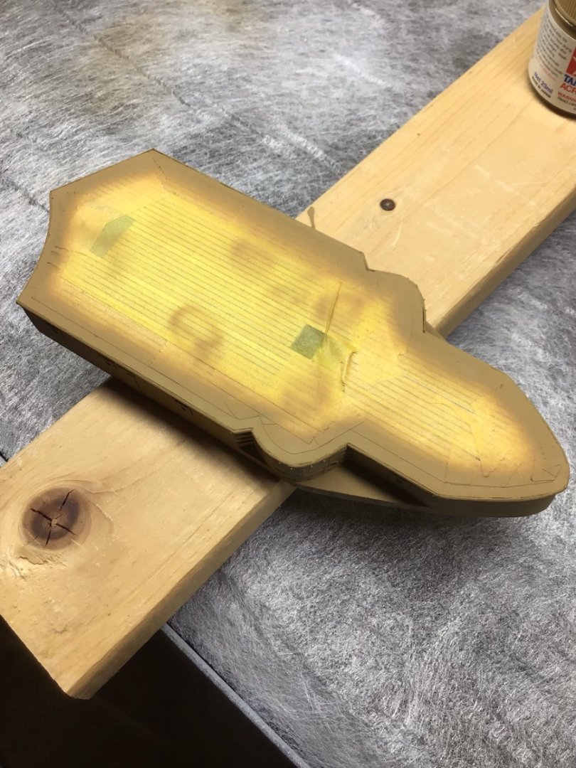
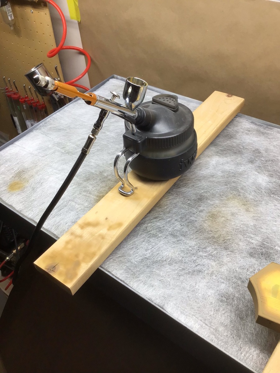
In my world, “Buff” is Tamiya Desert Yellow (XF-59), thinned 20% with Tamiya XF-20, and was applied with a Paasche Talon configured with the #2 tip, @20# pressure.My favorite Rickover quote is “the devil is in the details, but so is salvation”. Here the paint reveals gaps between the half round trim and the deck, that needs to be filled in. And notice the end grain along the rounded edge needs to be filled and sanded. I’ll let the paint cure for a few days before this work. Going to give Mr Surfacer 500 a shot for the filler.

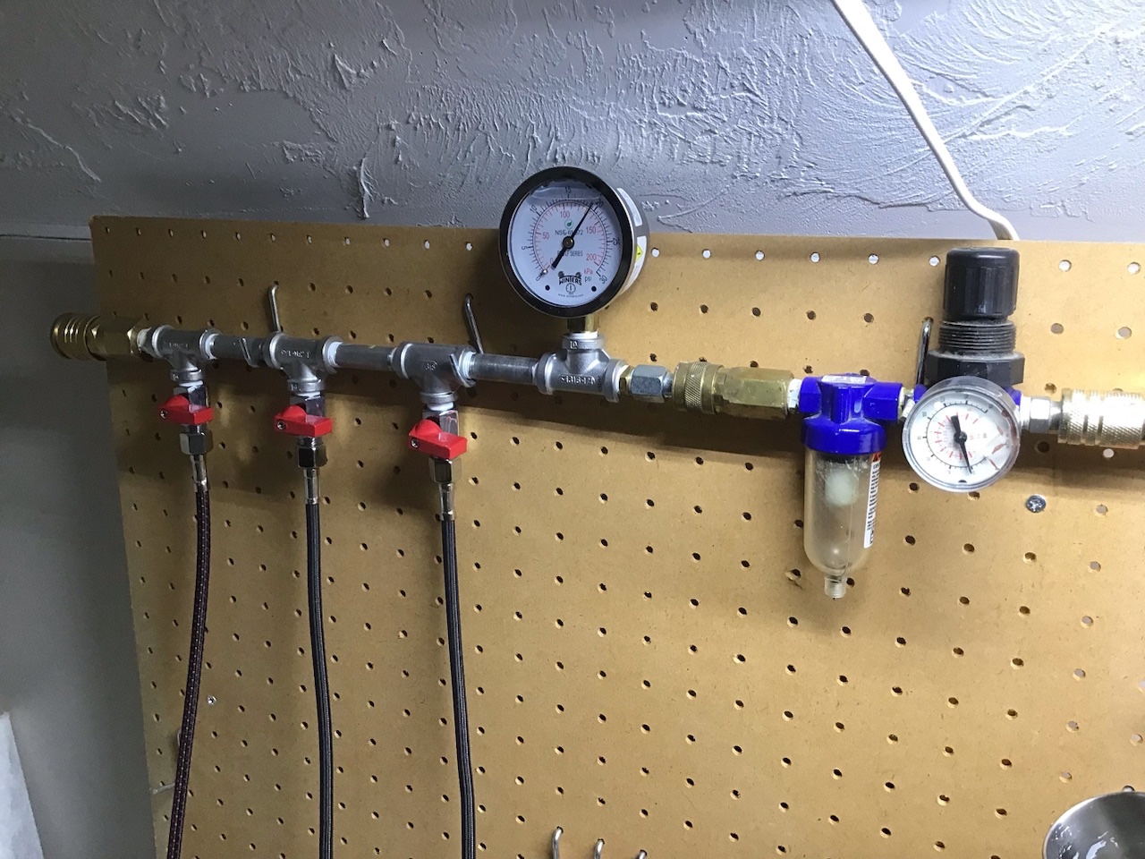
At the end, Tamiya Airbrush cleaner is run through the brush and exhausted into an Iwata airbrush station. I had my plumber friend make up a manifold with a 0-30# liquid filed gauge for greater accuracy, and ball valves from Paasche, available from Coast Airbrush. The table is by Artograph, shown without the hood.

- Ryland Craze, yvesvidal, Canute and 4 others
-
7
-
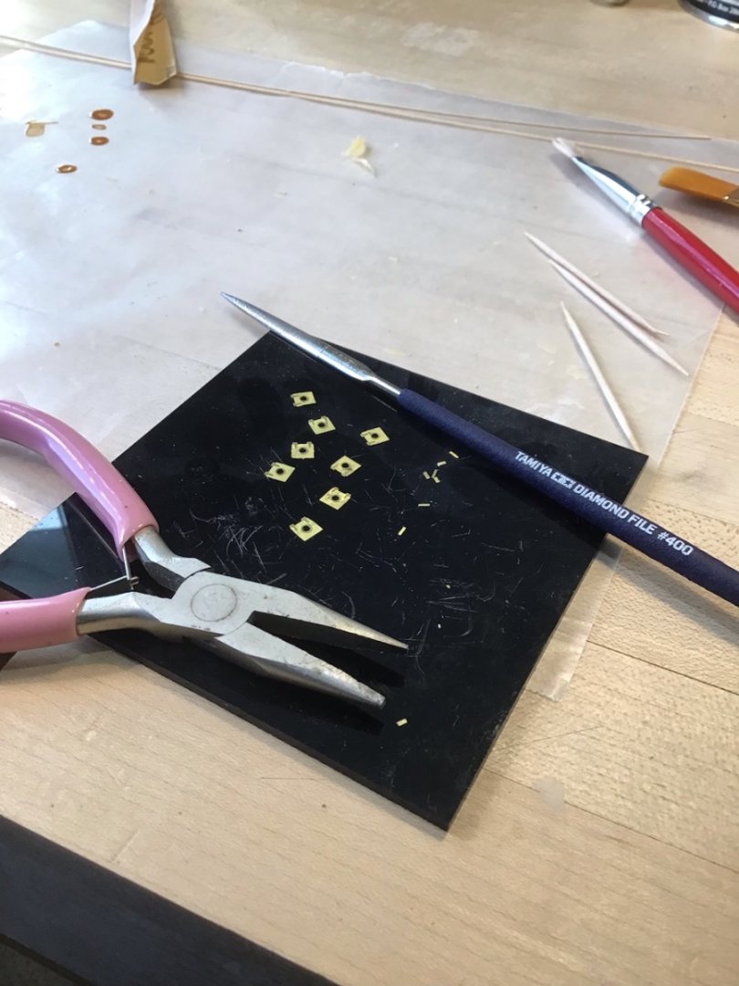
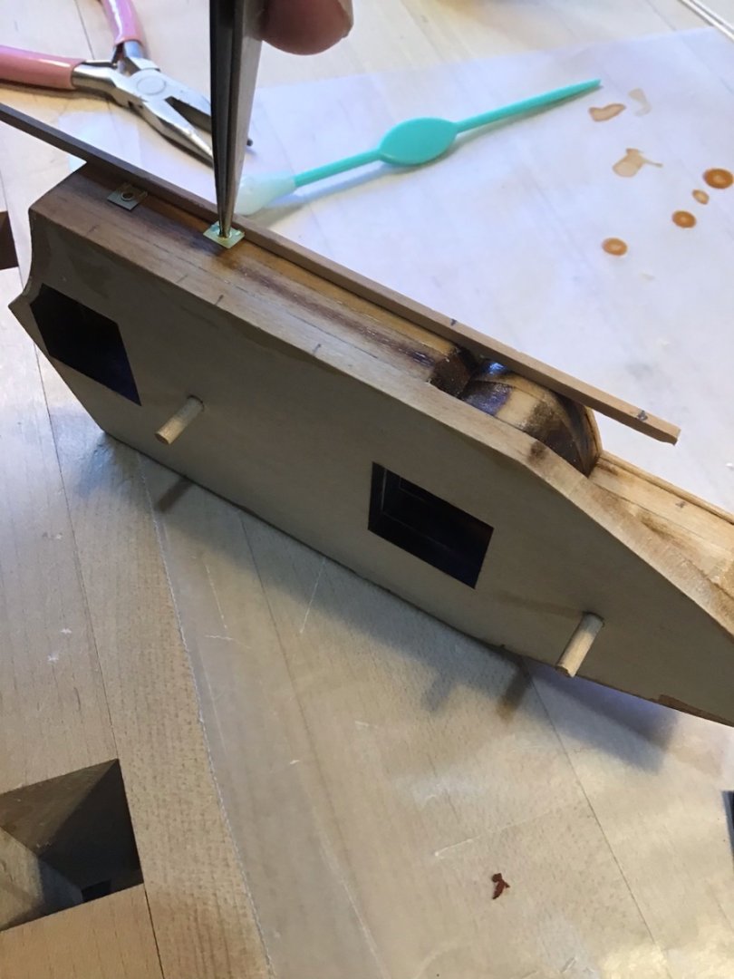
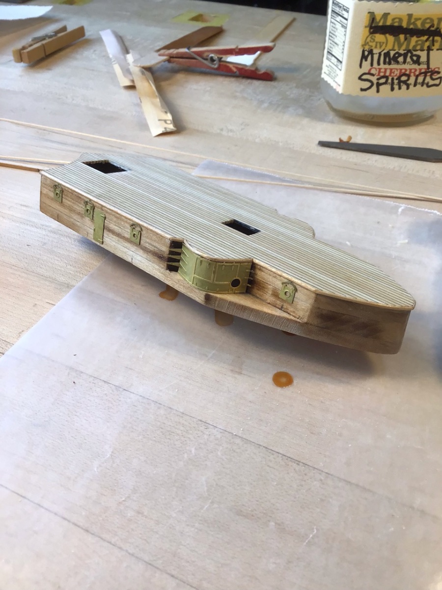
Forward Superstructure Photo Etch
Cut the photo etch from the sprue with an Xacto on a hard surface. Clean up the nubs with a diamond file - the Tamiya file has a fine cut and quickly removes metal.
To help with vertical alignment use a piece of stock against the half round trim. Notice the pencil marks at the base, to help with fore/aft alignment. The porthole panels were installed first followed by the ringlets.
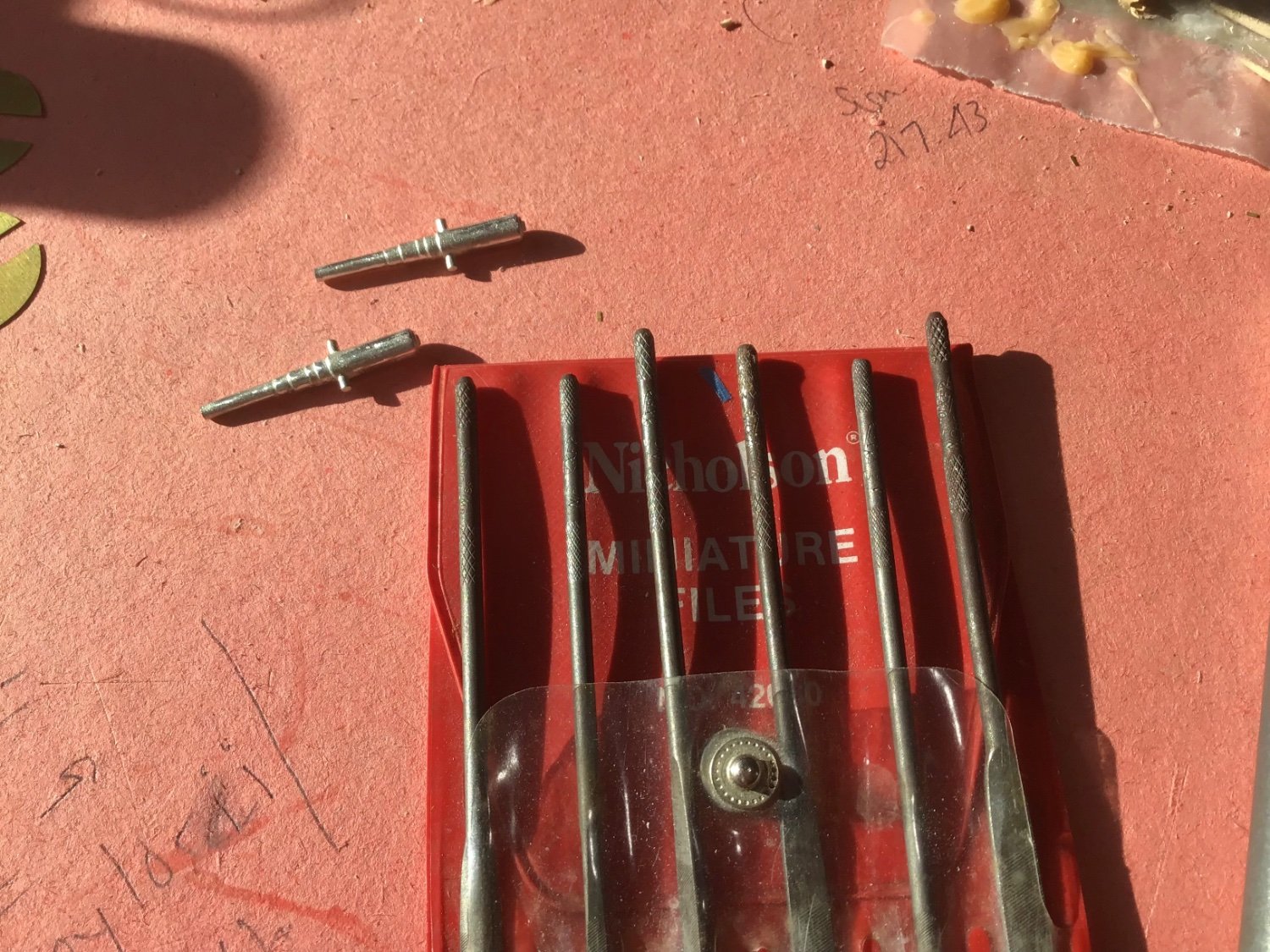
Use a rod to form the 6” gun casement panels. The rod set is from Small Shop.
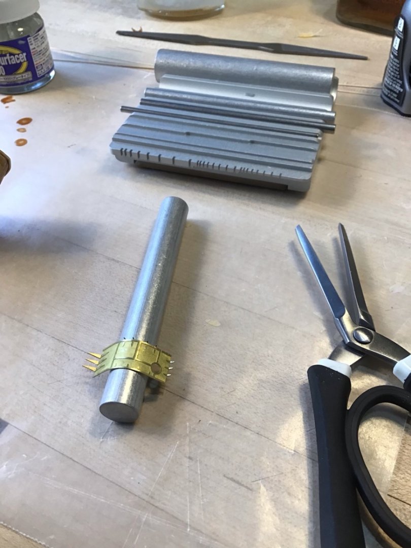
It’s important to get the casement panels shaped correctly so they fit easy along the bulkhead. I needed to file the bottom of the half round trim with a wood file and the casement panel with the Tamiya file.
To get the general shape, first hold down the aft end against the bulkhead, then make sure the aft hinges are at the correct angle. Then continue to wrap with the fingers. Next fine tune with the rod by working fore and aft from about the middle of the piece.

- GrandpaPhil, Canute, Ryland Craze and 4 others
-
7

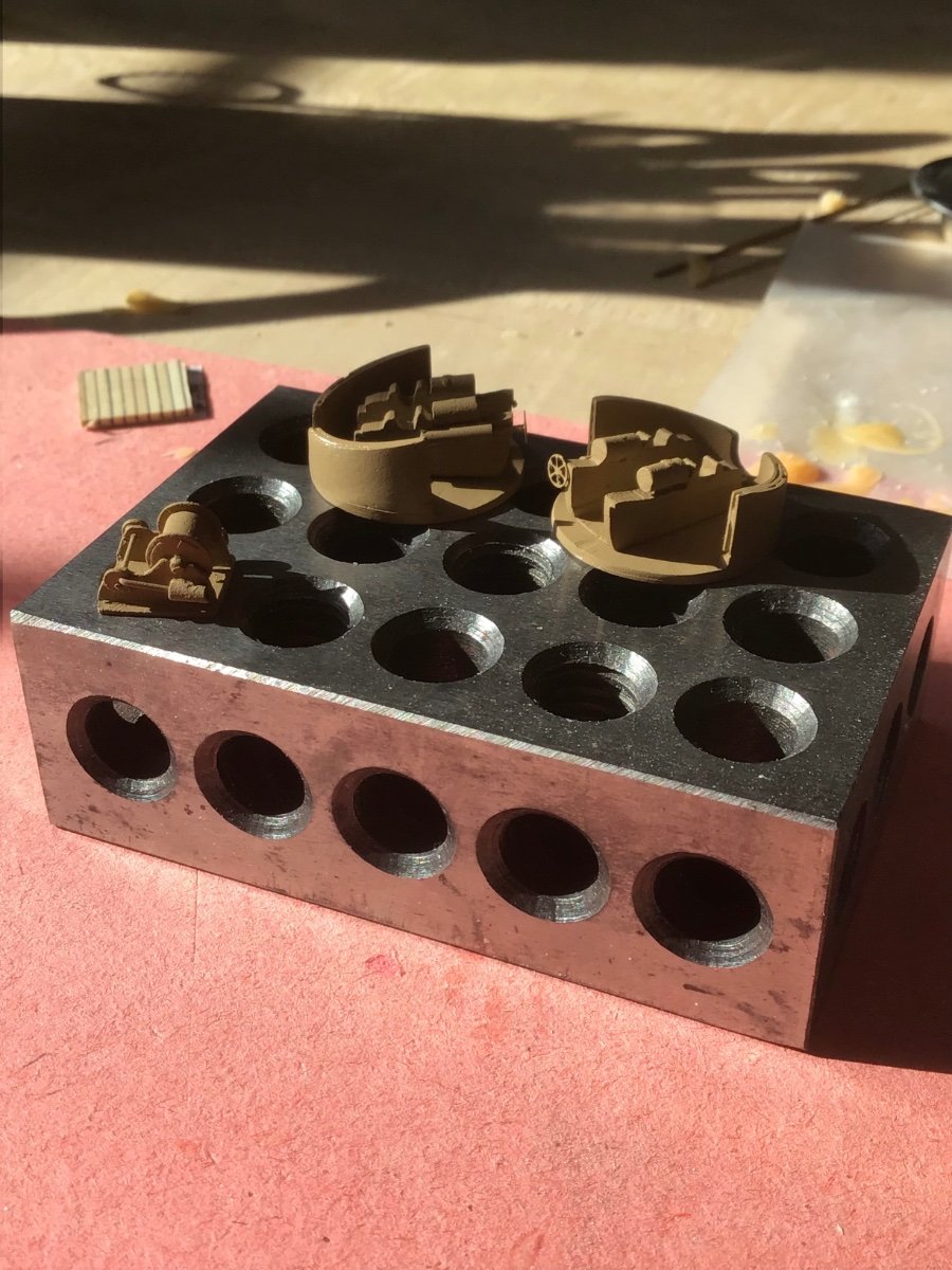


Britannia Fittings
in Discussion for a Ship's Deck Furniture, Guns, boats and other Fittings
Posted
Files are years and years old, work on wood….clean after use with a file card….