robbl
-
Posts
74 -
Joined
-
Last visited
Content Type
Profiles
Forums
Gallery
Events
Everything posted by robbl
-
 Have you ever read BRENTON'S NAVAL HISTORY? It has mention of this Blanche action among many other frigate actions.
 -
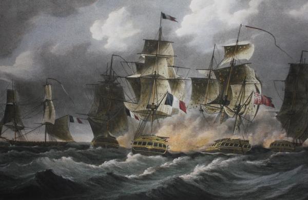
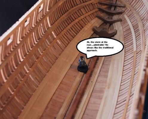
Hi Mark It is a photo of part of a print I got from the Maritime Museum showing the Blanche in her last battle. You can find it here: http://prints.rmg.co.uk/index.cfm?event=catalogue.qsearch&searchstring=PY8041 They scanned their negative and printed it. Here is my photo of the print which I have hanging in my modelling room to remind me of what I should be doing ..... Cheers Rob
-
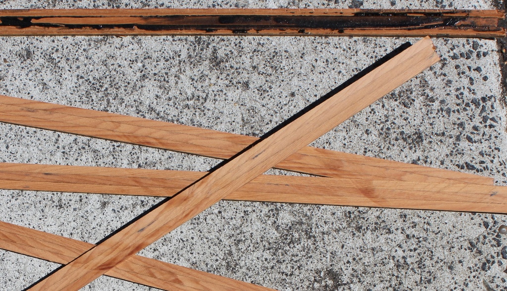
The kauri I have is not as nice as the totara to be honest. The totara that has been fence posts or something outside is a bit hard to put a nice edge on sometimes but has a nice dark colour, but the totara that used to be internal or furniture is lovely. That and the big block of totara I have are a nice reddy brown and cuts and shapes a treat. Matai is nice but the colour variation of the floorboards is apparent when used on the model. It works ok for the bulkheads though. I have some ancient kauri that was cut up from old church pews that I have yet to try out properly that might be good. I also have some rimu, and I like that to work with as well.
-
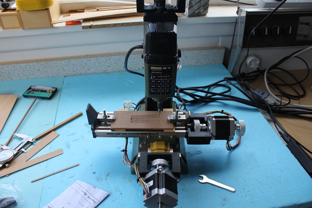
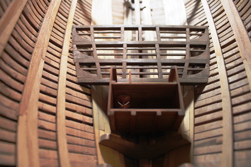
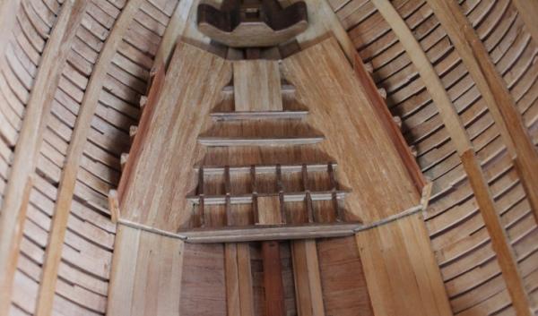
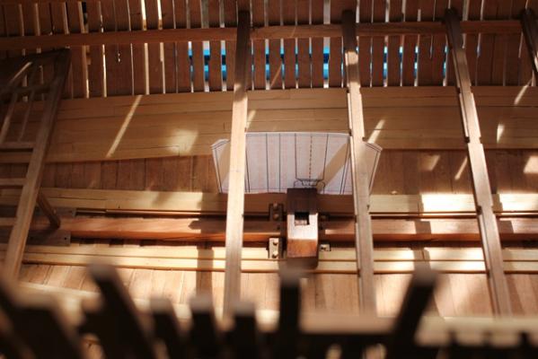
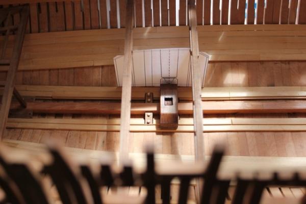
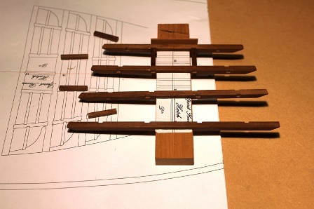
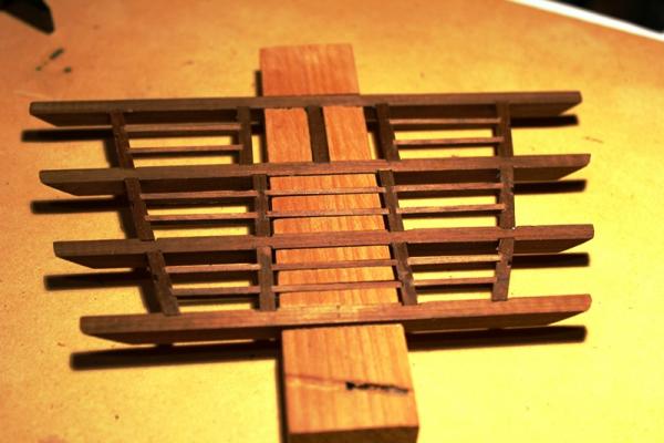
I am happy to see the end of 2014, as it was a year of health drama in the family and not a lot of building work at all, but there has been a little bit of progress in making the forward magazine and platform. I intended to build this in the same way as the aft magazine and platform, by building the both off the model to make it easier to work on them. I think it went ok, however I got seriously confused with my measuring and the platform was way too high at the bow, Some sanding of the platform and the clamps remedied that, and the magazine fits comfortably under it in place. Next for these will be completing and fitting out the magazine and adding the filling room, light boxes and structure that surrounds the foremast step before fixing the platform in place over it. I think I will have to fit the bitt pins in place as well. The first few pictures show the magazine being formed by first laying out the beams then the planking. It currently finishes where the light boxes will go and will later be extended forward. As I mentioned above, the platform was built mainly off the model. There are still a few ledges to be fitted, but it is mostly complete apart from planking and a couple of timbers forward. Finally, where would I be without my toys. Making the knees has been relatively easy since I fitted some CNC gear to the Proxxon mill


- 82 replies
-
- 14
-

-
Hi Jan You pose a very good question that I have spent some time pondering. I have, a couple of times, tried to get an idea of what figurehead to use but with no luck. It is something I intend to look at later and will probably need to research it correctly rather than try to google it. I have a couple of books on figureheads, but they haven't helped apart from being good reads. Are you going to rig yours? Cheers Rob
-
Here's pics... and for those who wanted it.. a picture of (naturally) the sawdust from cutting the pieces. Ahhhhhh, there's nothing like the smell of sawdust in the morning ....
-
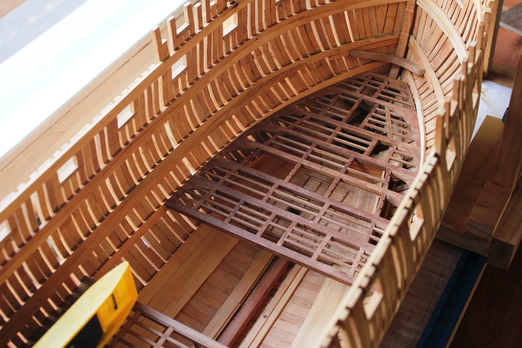
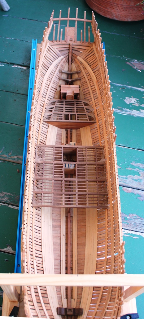
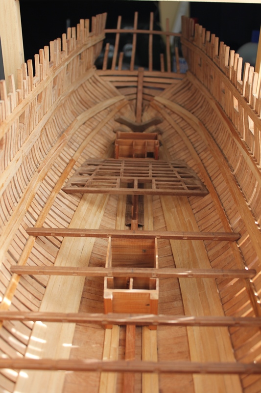
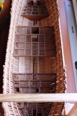
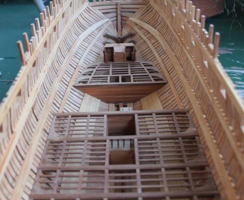
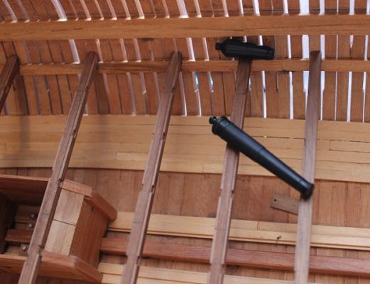
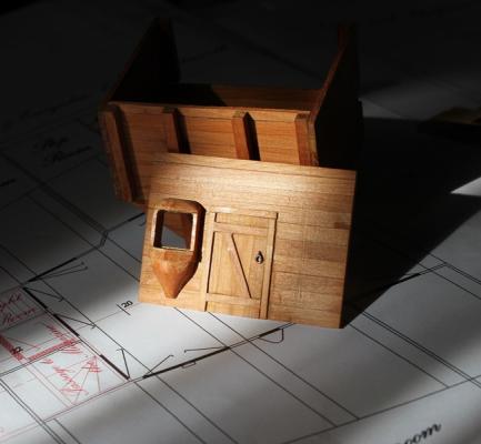
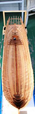
Hi all Being distracted by new toys, followed by work, I haven't done much that was photo worthy, so I thought I would post a couple of "proof of life" shots having just finished the orlop deck framing. In the background of the photos you can see the aft magazine with roof and hoods on. Some scratches still need to be smoothed out on this, and the flash makes it look worse than it really looks. There are bulkheads still to go in either side of the aft magazine, and the platforms will be planked, but until I start work on the forward magazine and platform I won't decide how much to plank. At this juncture I would say I am not a fan of carlings and ledges .... only the fore platform, two full decks, quarter deck and forecastle to do, then no more of them - yay! Cheers Rob


- 82 replies
-
- 18
-
-
When you start putting frames/keel etc into that, how do you stop it sticking to the mold while gluing the joints? I thinking treating the mold with oil might do it? or is that what the furniture polish will do? I only ask because my construction technique involves glue getting all over the place..... Cheers Rob
-
Proxxon PD230 metal lathe and CNC kit short review
robbl replied to robbl's topic in Modeling tools and Workshop Equipment
Ah ha! Thank you David, that helps a lot. Cheers Rob -
Proxxon PD230 metal lathe and CNC kit short review
robbl replied to robbl's topic in Modeling tools and Workshop Equipment
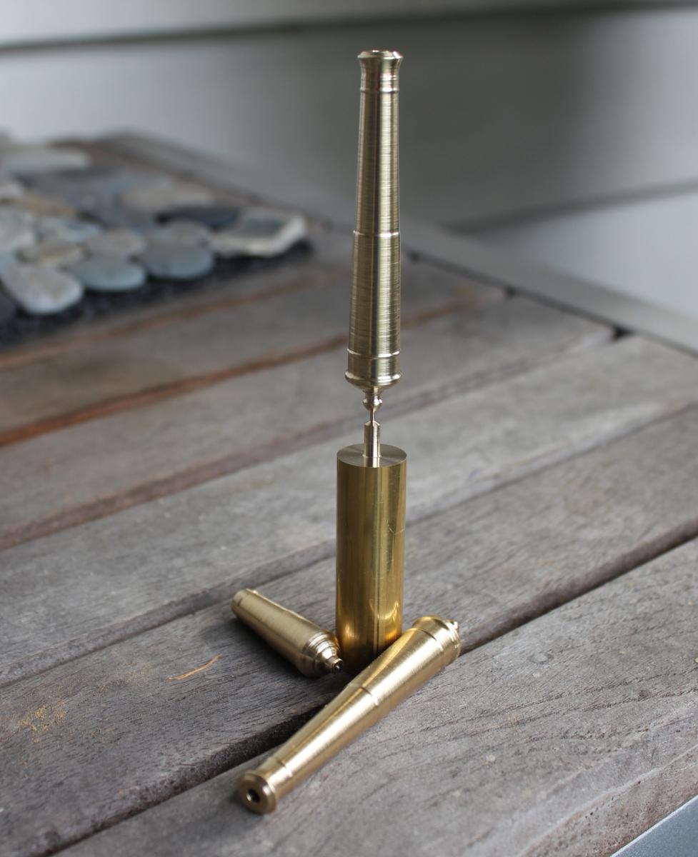
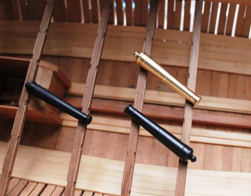
And this year's "Cannon Award" goes to ...... Getting better but a couple of fixes to make yet. Finish was ruined because, as I found out, turning the thin area behind the breech causes the rest of the barrel between that and the tail stock to move slightly .... tarnation! I will have to make that step happen after the fine finishing turn of the barrel. To give an idea of accuracy, I had the lathe turn a length of brass down to 0.2mm. The rod connecting the barrel to the pedestal in the attached picture is .9mm Cheers Rob
-
Proxxon PD230 metal lathe and CNC kit short review
robbl replied to robbl's topic in Modeling tools and Workshop Equipment
Hi Brian, sorry should have added the specs. Centre distance: 230mm Editing the first post to add tech specs and a couple of photos of wood turning. Cheers Rob -
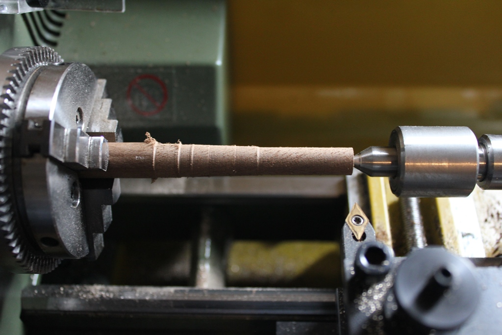
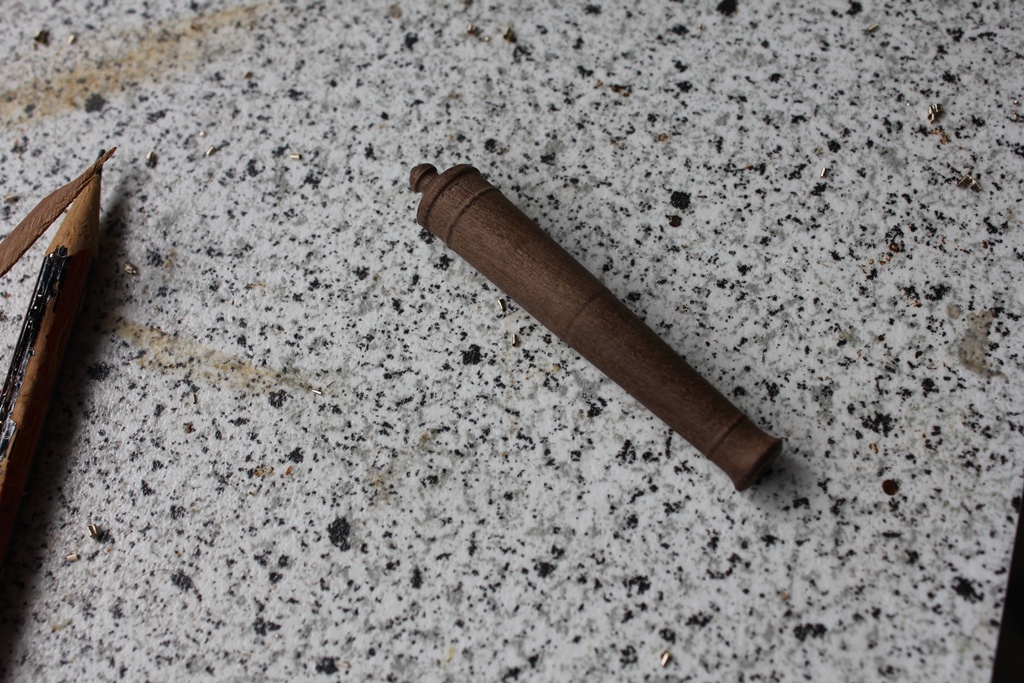
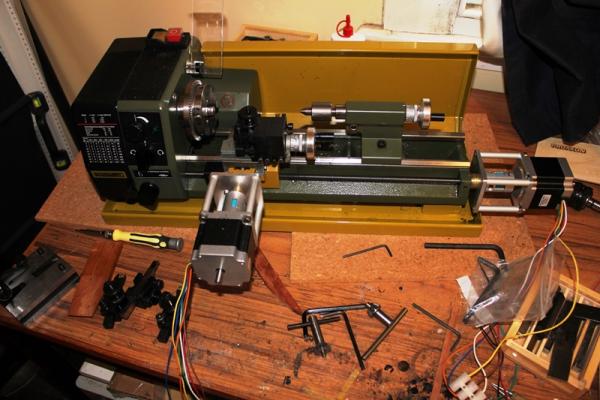
Having cleared the cupboards of some my old unmade plastic models and generated some spare cash, I finally splashed out and got a metal lathe, so I thought I might make a couple of notes about it. I am a lathe novice, so if I get terminology wrong, I apologise. My requirements included: Light weight so it can be stored in a cupboard or moved outside for use Able to turn 45 mm diametre (I hope to make a 1/24 scale cannon and a carronade) Able to use a variety of tools Able to take a CNC kit to repeat jobs accurately and to cope with tapers and curvey bits Locally in NZ, the Sieg machines and a lot of clones are available. They are cheap but quite heavy at between 35 and 55kg for the small ones. So in the end I chose a Proxxon PD230 which weighs in at 10kg with its clothes off, can turn up to 56mm, can use small lathe tools (up to 8x10mm tools) and has various CNC kits available on the market. Technical specifications: centre distance: 230mm swing: 52mm height over cross slide: 28mm cross-slide travel: 60mm top slide travel: 45mm steel toolholder: accepts 8mm x 8mm cutters spindle bore: 10.5mm thread cutting capability: 0.5mm, 0.645mm, 0.7mm, 0.75mm, 0.8mm, 1.0mm, 1.25mm, 1.5mm spindle speeds with reduction: 3,000rpm, 900rpm, 300rpm automatic feed resolution: 0.05mm/rev or 1.0mm/rev tailstock spindle: MK1 bore (short) tailstock travel: 30mm internal chucking capacity: 2mm - 35mm external chucking capacity: 24mm - 68mm handwheel resolution: 1 revolution = 1mm feed (40 divisions) mass: 10kg dimensions: 530mm x 250mm x 150mm The lathe came with 3 jaw chuck and live centre and a few bits and bobs for threading and gear cutting, which I do not plan on using. In addition, I got (over the following couple of weeks) splash guard/tray Quick tool change post plus extra tool holders Proxxon's HSS tool set (5 tools) Fixed steady Boring tool set Tail stock drill Tool holder for rotary tools (Dremel etc) Set of 7 indexed tungsten carbide tipped tools (on special from sieg shop here) The 8mm high x 10mm wide tools fit in the tool holders made for the quick change tool post. Out of the box, the PD230 is almost ready to fire up after a quick check on the various fittings. It runs surprisingly quietly, and is very compact (in fact the lathe could sit inside my HMS Blanche). I got some Acetal (Derlin) rod for practising on and created a bit of a mess which pleased me no end. With the tools all adjusted for height and distance from the centreline, it is very easy to swap tools around in the middle of a job. I got used to facing and general turning (the lathe has an automatic feed if required) but the one task I am struggling with is parting and deep grooves. At the moment I am avoiding both tasks by using a saw. The CNC kit came from Ideegeniali.it, and it arrived shortly after the lathe did. They claim it only takes 5 minutes to assemble, but it took me about 10 minutes ... but who's quibbling. Wiring it up wasn't difficult either, and then it was time to consider the control software. I chose Mach3, which requires a PC with an printer port. That took a bit of finding, but after a bit I had everything hooked up and ready to go. Ideegenialli supply configuration files for Mach3, so apart from a couple of minor tweaks the computer soon had control over the lathe, with the ability to make moves in the X and Z axis rapidly or jog tiny distances. With the kit in place, I can still manually work the lathe, although I need to remount the original hand wheels onto the stepper motors to make that easier. I already have a CAD/CAM program, so the next step was to create something. I worked up a drawing of a carronade and a cannon from Wayne Kempson's plans in Allan Yedlinski and his book Euryalus V2 and started testing. The testing taught me a few things about tool selection and pathing, as well as how to cope with the complex shapes, such as the breeches of the cannons and carronades. Under CNC control, the carronade can be turned in one job (several passes) with a single tool, while I am turning the cannon first from the barrel back with one tool, then flipping it in the chuck and turning the breech end using two tools (here the quick change post comes into play). I still do facing, drilling and parting off manually. The jobs are not perfect yet, as I have a couple of issues to work out: When I flip the cannon to turn the breech end, the chuck marks the barrel. I am contemplating leaving a V groove oversized in the barrel to slot the chuck into the barrel, then manually turning that out at the end of the job. The finish is not as good as I would like, which I think is a result of tool choice. When turning from the left or right, it is really nice, but the 55 degree straight tip is leaving grooves. Multiple finishing passes clean these up, but a better tip might be a plan. Parting ... if I can't do something manually, then there is no way I'm going to do it under CNC control. I think I have the height correct (on or slightly higher than centre) and am feeding slowly, but it just doesn't work well for me. This may be due to the plastic bending away from the tip, then trapping the tool as it flexes - brass may be better. Or I am parting to far away from the chuck, or with the part still under pressure from the tail stock it is trapping the tip. Conclusions: Pros: The lathe is more expensive than others, but meets my requirements for space and capabilities. Accuracy of the lathe is impressive, but I can't compare to other brands. The CNC kit works well and lets me do things I think I would struggle with (complex curves and repeat jobs) Both the lathe and the CNC kit worked straight out of the box. I spent (and still spend) a lot of time looking for hints and tips on turning - that is time well spent. Con: The operator is a bit inexperienced and could do with a bit of learning. Overall, a nice machine to have and I am glad I finally took the plunge. Cheers Rob PS: some wood turned - old walnut dowel from an old damaged kit.


-
The CNC mounting parts and controller were a kit from Italy, and took about 10 minutes to set up. Motors, power etc can be sourced locally.
-
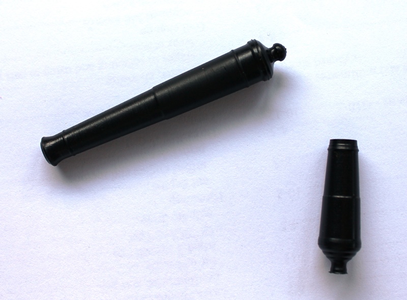
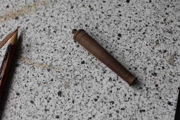
Hey Daniel, there's no such thing as a bad question. If people didn't ask "why is that like it is" I wouldn't go back and correct the deliberate errors I make to test peoples' observational skills....... Nils, every time I look at the forum I see new things to try and parts to make - the work done here is inspirational to say the least, for example your Pamir. As for me, no progress this week. Not even a little bit. I have a good reason though. The Admiral wanted some special knitting needles made to knit rugs with, so it was plain to the simple deckhand that a tool was required for the task....... Obviously a CNC kit would be beneficial to optimise said deckhand's time in the yard......(What can I say, I work in IT, lived with computers since 1976 and remain fascinated by geek stuff, love toys of all types and this thing is just immense fun.) Haven't started on the needles yet, but have done some test subjects just to be sure I get them right .... Here we see examples of a "pointy" end that didn't meet specifications for wool handling. And apparently they were too short .... sigh, I shall just have to try more "tests" and , ok, I admit the whole needle idea came up after the lathe arrived.... This is the third attempt on both the carronade and cannon (we don't like to talk of the 2nd attempt at both - hair raising would be an appropriate comment, if I had any). I am practising using Acetal (Derlin) plastic rod which I believe is hard to glue bits to, so brass will be the final material - I just have to get brave enough to see the metal fly and then relearn soldering - fortunately there is a very good thread on soldering on the forum. However it is back to the "real" work this weekend, I promise. Oh, and the needles.....mustn't forget the needles.......

- 82 replies
-
- 15
-
-
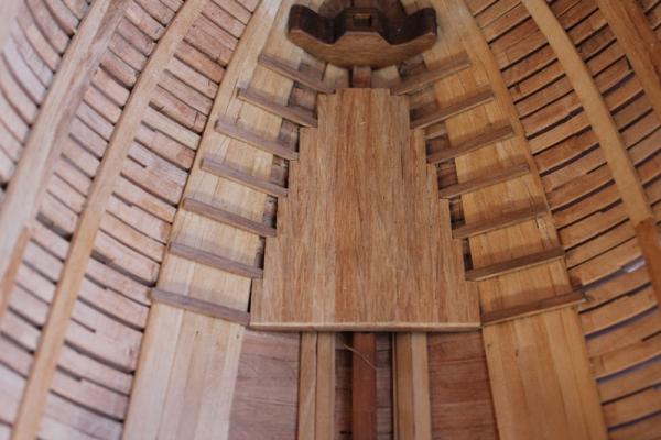
Hi Mark, yes the fore magazine is a much larger work area and the aft one was for storing filled cartridges, so the work area didn't need to be big I guess.
-
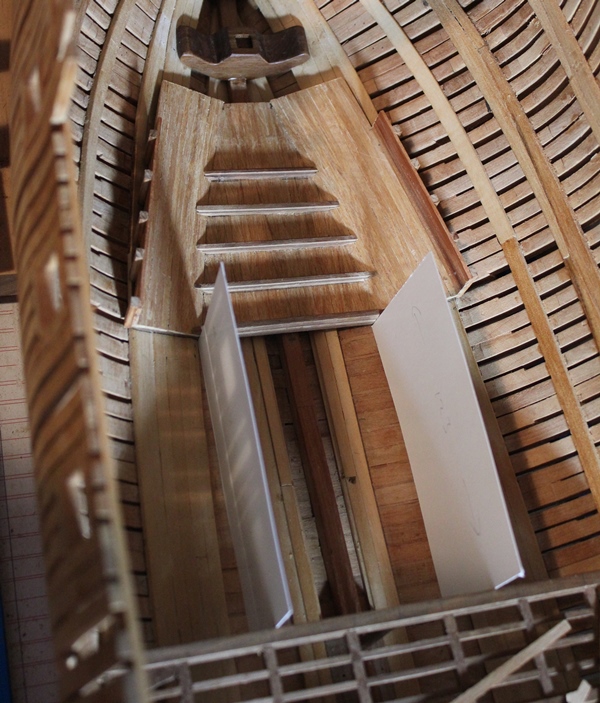
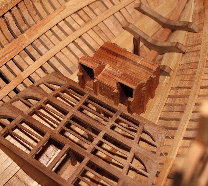
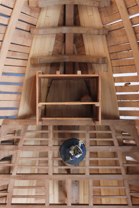
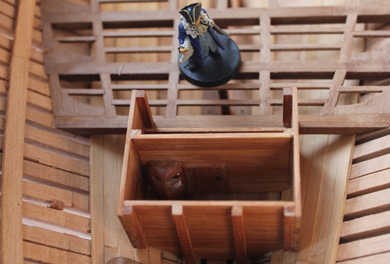
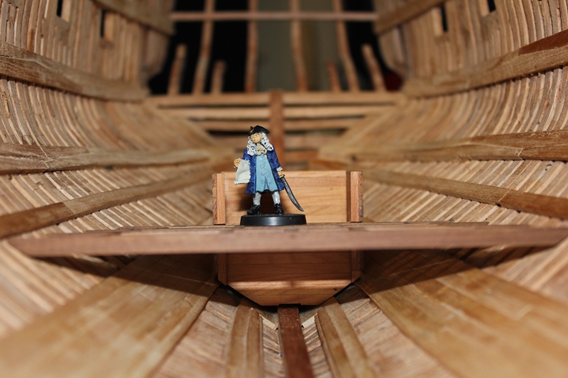
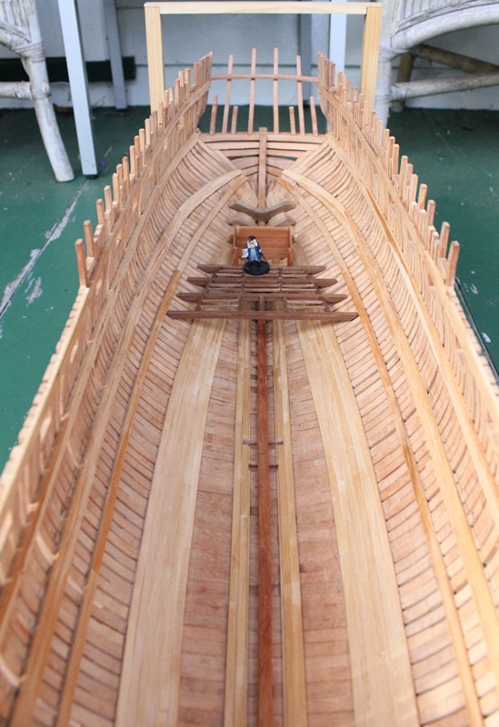
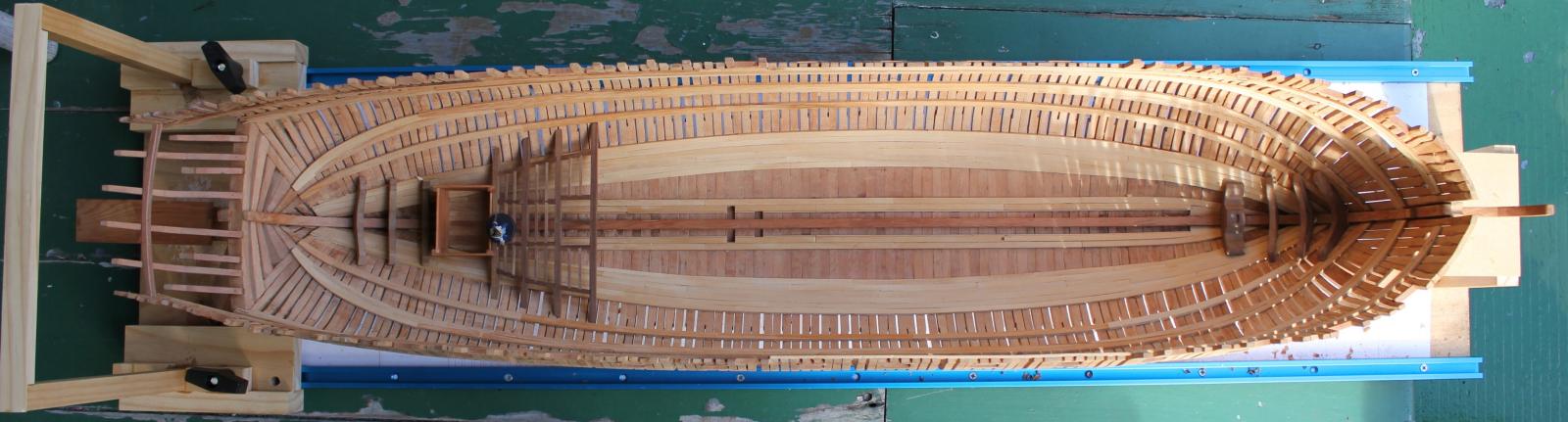
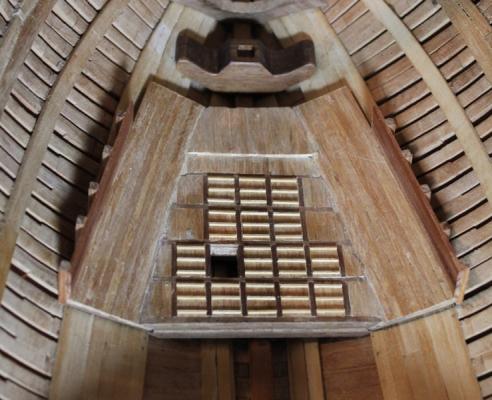
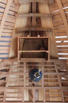
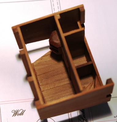
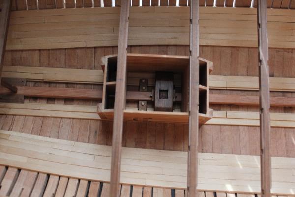
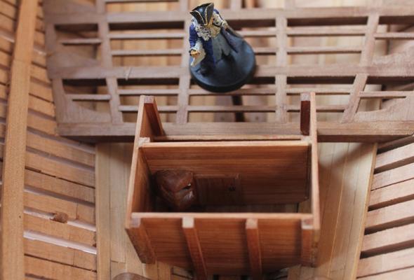
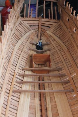
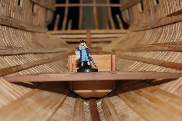
This is a top down view of the magazine to show how small it is. Note that Admiral the Lord Bob is a tad rotund and unlikely to fit through the access passage and doors. It is not glued in place yet as I will do the floor pallets (perhaps) and the cartridge racks off ship, as well as needing room to fit some bulkheads below the platform. (Actually this photo was taken before adding the internal doors and access steps.)
-
Egen, that makes sense, I had not thought of that. Perhaps I should look closely at that part of the gundeck and do some planning. Daniel, 42mm fore and aft (6ft 6in) x 57mm wide (8ft 11in). Even the doors are low, so it would have been a difficult place to work. And, yes, your comment had me running to the plans When the racks go in there will not be much floor space.
-
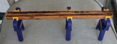
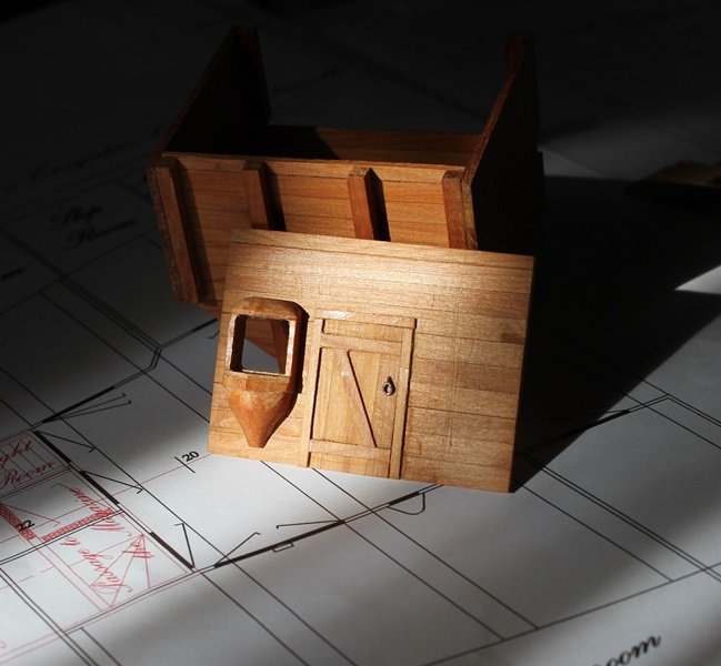
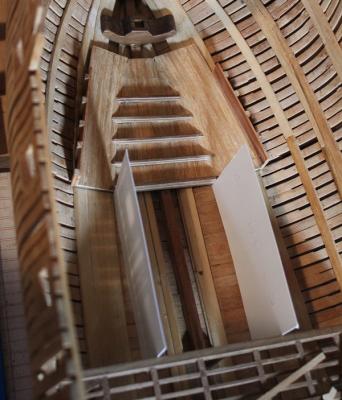
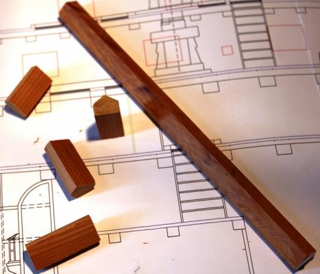
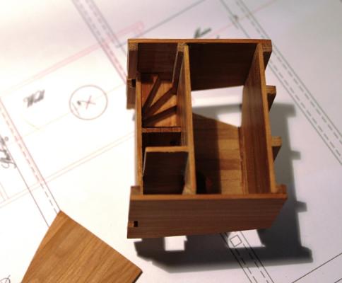
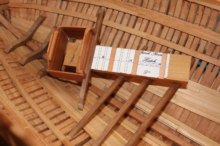
Getting there Allan, just have to finish these platforms .... And Druxey, I suspect the blood is a sign - a message to suggest it is time to wrap it up for the night. This update is just a note to show that I'm still at work, even if the progress doesn't show. I had been working on the aft magazine and got to the point of working on the light room. As there will be more light rooms in the forward magazine, I decided to see if I could mass produce these. To do this, I ripped a length of wood (Matai), then using the tilted blade on the table saw, cut the angles profile of the light box. Then I milled out the enclosure to make a rough box .... (this was a test piece that was discarded) Which I then carved to form my interpretation of the light box .... ....Which was then discarded as the door was Too high Too wide The cross boards were round the wrong way. But the photo was quite good so I kept that I then added the window frames to the box (but haven't done any glass for it), and it now resides in the magazine. I had also added the "spiral staircase" access ladder as well By this stage, I had spent considerable time working on this tiny room that in all likelyhood will never be seen ..... when the Vacuum God visited and sucked up my newly built light room access ladder I took this as a sign that I should take a break from the Aft Magazine, and move on to the middle platform and lower well. So I left the aft platform in this state .... And moved on. The deck beams were easy enough to do. I chose not to do any round up on them, milled the rabbet for the deck planks and chiseled the mortices for the carlings. Having checked their heights when sitting in the notches chiseled in the orlop deck clamps, I then started on the lower well. At this point I found I had a problem. The main mast step sits too far back if I allow room for the elm tree pumps (frame 7 aft), so has to be moved forward over the recesses. I am unsure what I might have done wrong here, but to be honest I am comfortable with the way everything is sitting. I wonder if the elm tree pump recess should have been in frame 7 fwd and not 7 aft, or perhaps 8 aft, aft of the step and fwd of the chain pump recess? In this shot, the aft of the step is sitting on 8 fwd and extends over 7 aft, covering the recess. This is the well in place, the main mast step has had the bolts and wedges fore and aft added, and I have put two blocks with dowel in place for positioning the chain pump shafts later. Regardless of the above issue, I am more than happy with how the middle platform is turning out so far. I am adding limber boards under the platforms as I go, mainly to try and stop all the scraps falling into the channels. When I get to the forward platform, I will be returning to the aft as well to add the racks and other furniture. Cheers Rob


- 82 replies
-
- 13
-
-
Perhaps post the questions in the Ship plans and research sub forum,or perhaps the nautical history one. Plenty of knowledgable folks around. Cheers Rob
-
Hi Ame At the quarter deck the rail of the model sits 230mm above the keel, and a rough measure would suggest the main mast incl. top gallant extends another 840mm above that - or roughly 1070mm at 1/48 scale. Cheers Rob
-
Last order I placed in January arrived in New Zealand 8 days after placing the order.
-
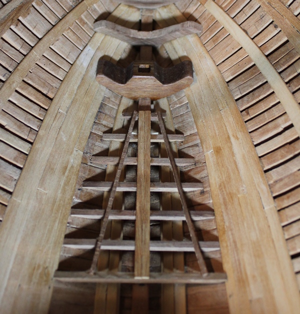
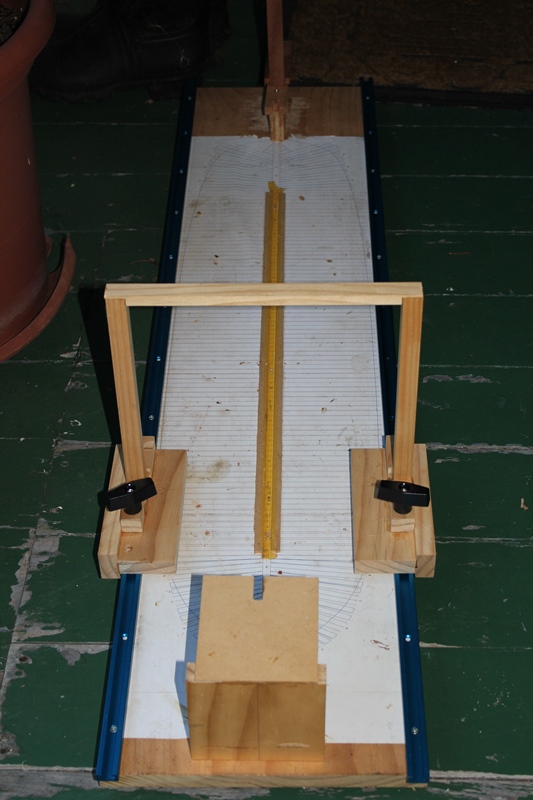
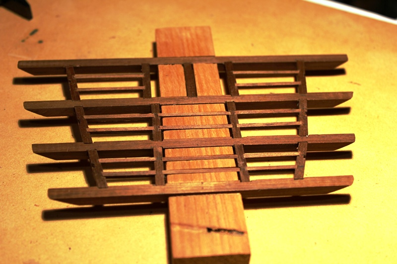
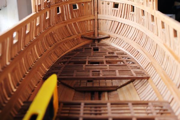
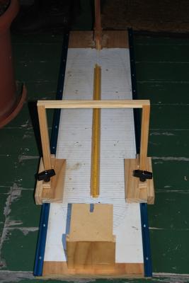
Hi all A little bit of progress internally. First, I added t-track and bolts to the building board so my gantry can be used for height measurment and clamping. Then, a new assistant supervisor was appointed..... Retired Admiral the Lord Bob brings experience to the task. Then, to learn about making decks and platforms, I decided to start with the aft magazine and platform, as it looked a lot simpler than the fore platorm. First I used the bulkheads I had made from Matai in the last progress post to construct the walls of the aft magazine. And I also cut the aft platform beams from Totara, and checked their positioning for height along with the magazine. I started with the idea of milling the mortices, but that took longer than cutting them with a scalpel and small chisels. This effort highlighted two things - I need smaller chisels and I need to cut away from the hand ... blood is on the underside of the beams. At this stage I realised my potential for getting all the angles and measurements wrong while working inside the hull was immense, so made slots in a piece of offcut wood to allow me to construct the platform off ship. This allowed me to line up the timbers and their mortices and hold everything nicely in place while I worked, so I ended up with this.... Which when placed back in the hull with the magazine looks like this .... So I still have to do the knees, and until I do, the platform will not be fixed inside the hull. You might notice, in the close up of the top down image attachment below, the magazine has its floor planked (Rimu), next for it will be the internal bulkheads, lightroom fittings and doors. The "jig" for the platform worked so well, I plan on continuing that method for the orlop deck and fore platform, however I want to finish this aft area first. oh, almost forgot, another "take-away lesson" from this was to avoid the use of blu-tack to test fit the beams in place ... it was difficult to get off afterwards. Cheers Rob


- 82 replies
-
- 14
-
-
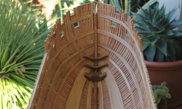
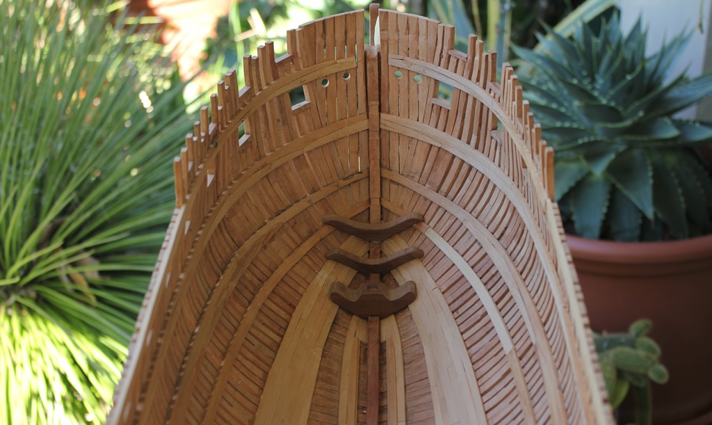
Thanks Gary and I agree regarding the shape of these ships, the lines are beautiful and I guess that's what draws us to them. Hi Allan, it's good to be back at it, and there'll be a couple of questions flying your way soon, that upper deck transom is probably weeks or months away but it niggles at me all the time When's your next book being published? Cheers Rob
-
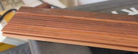
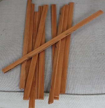
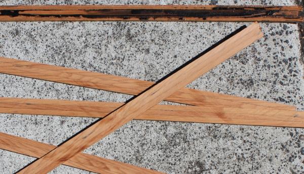
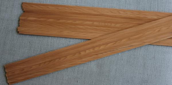
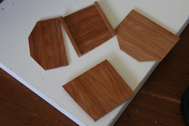
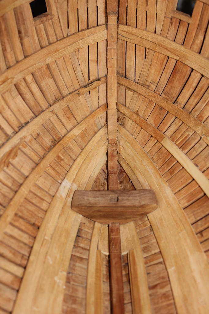
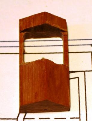
More sanding done, yet more to do. While doing this, I contemplated my first attempt at the foremast step and was not impressed. So I ran it through the mill, then gave it a good sanding (does that task never end!!) And am now happier ..... while I was at it I did the first two breast hooks as well, The other thing I have been thinking about is the building of the internal structures, such as the aft magazine. First on the agenda was experimenting with creating the bulkheads. Starting with a length of tounge and groove floorboard I cut lengths of 4mm thick strips Then glued 3 of the strips together and then ripped them down to 2mm strips ending up with 2mm thick lengths of 3x4mm boards which I then glued edge on to make wider sections, which I then ran through the thickness sander to get them smooth and down to 1.6mm thick. So, a successful few days avoiding sanding Cheers Rob