Dan Vadas
-
Posts
3,261 -
Joined
-
Last visited
Content Type
Profiles
Forums
Gallery
Events
Everything posted by Dan Vadas
-
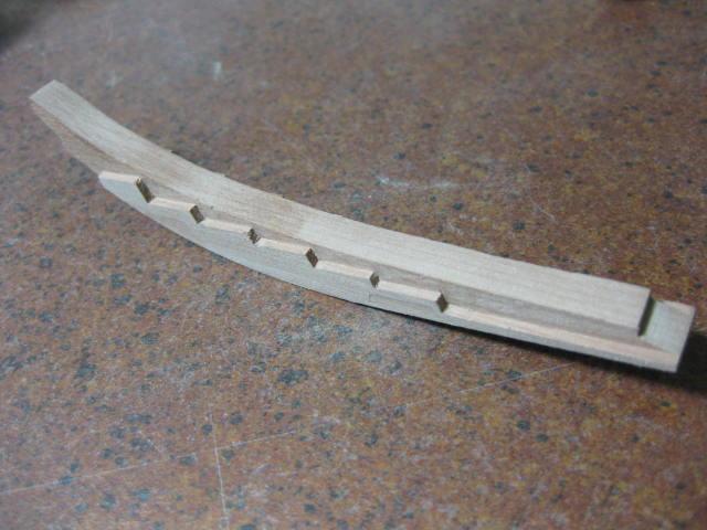
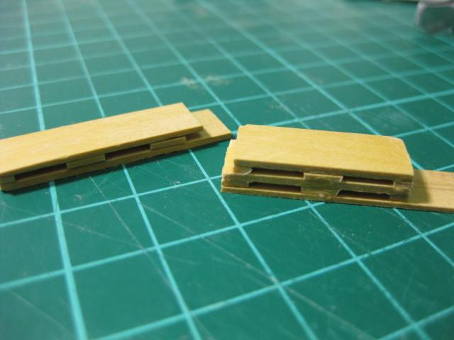
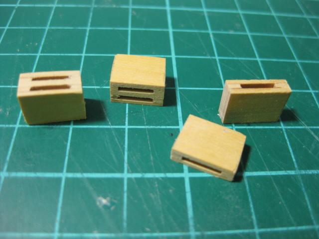
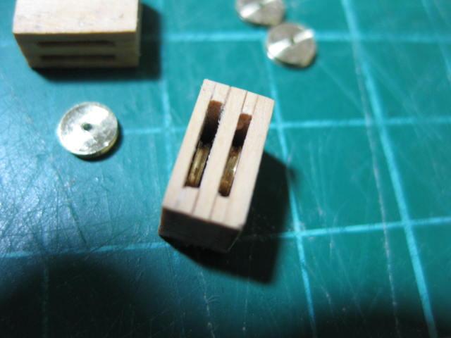
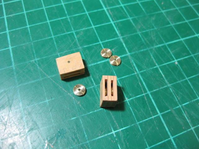
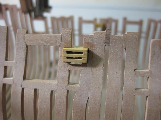
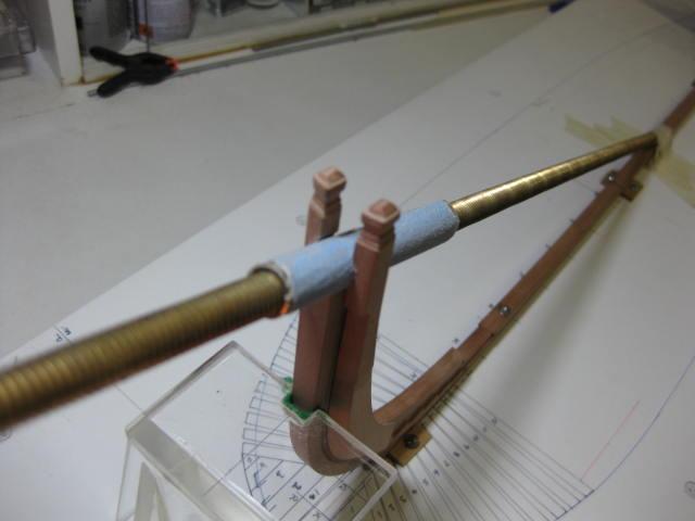
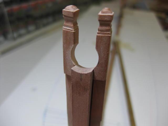
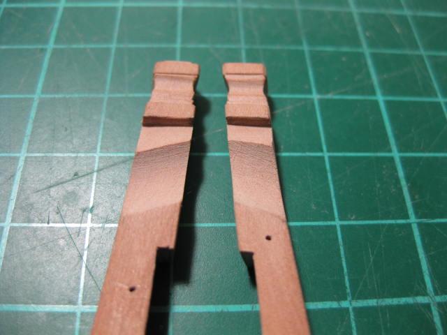
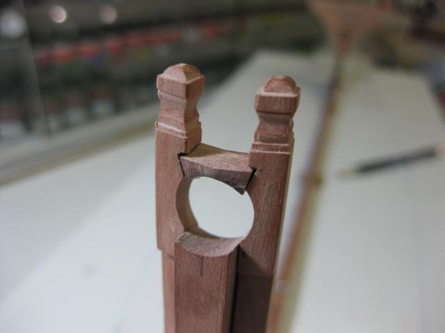
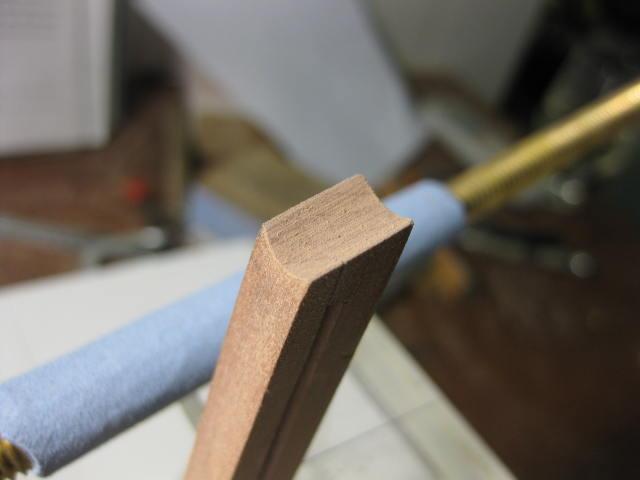
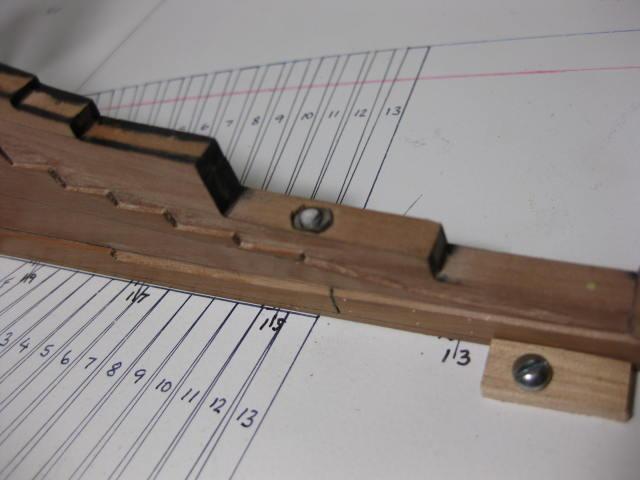
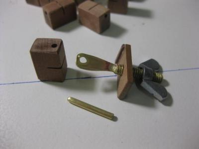
Fixed Blocks There are two Fixed Blocks each side of the hull in the Waist - one single and one double. The single block is for the Main Tack, and the double block is for the Fore Sheet and Spritsail Sheet. These were made by laminating spacers between two strips : They were then sanded to size on the disc sander and the slots were cleaned up with a thin needle file : I turned the Sheaves on my lathe. The larger ones are 0.9mm thick and the smaller ones are 0.75mm thick. They are 4.8mm in diameter : The blocks were later morticed into the frames :
-
Shifted Toptimber Toptimbers were "shifted" to maintain the correct opening sizes for the Gunports etc. The one shown in the first few pics below (the first one I'd ever made) was actually re-built later on, as I'd miscalculated the correct amount of "step" needed at the join : The re-built frame after being fitted :
-
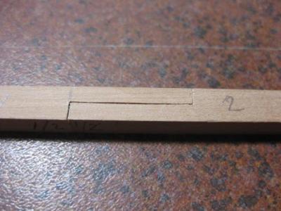
Frame Bend A Frame Bend is used in every third frame. This is two frames joined together with a spacer block - in reality these were bolted together. I've only used two spacers on the unseen Port side :

-
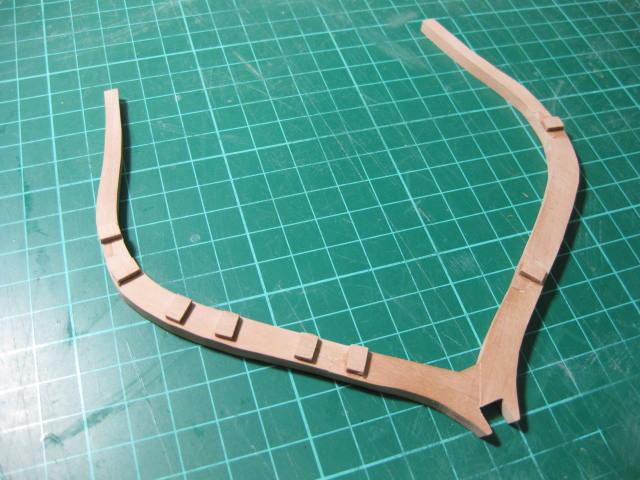
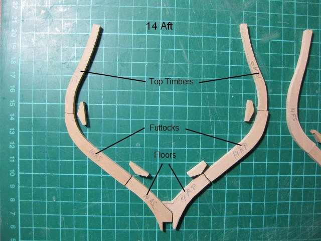
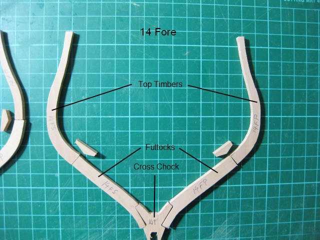
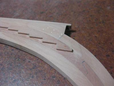
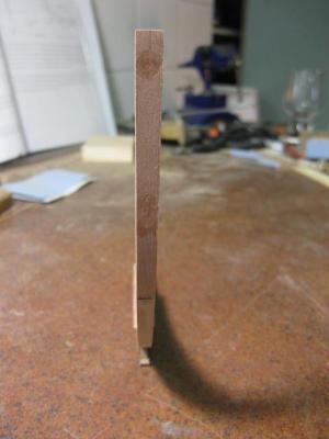
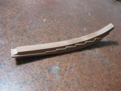
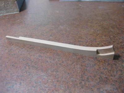
Aft Square Frames I traced the printed CD patterns on Mylar film, transferred them to the timber and cut them out to the largest extents. Then I used double-sided tape to hold them in position on the patterns and glued them together : The two pics below show the components of two typical adjacent frames. Note the differences in the positions of the joins, and the extra Floor in the lower one. The scarf joins for the Chocks in each piece have not been cut yet : The frames were fitted to the keel using a large Squaring Jig. A square was used to align the outer edges to the plan marked on the baseboard :
-
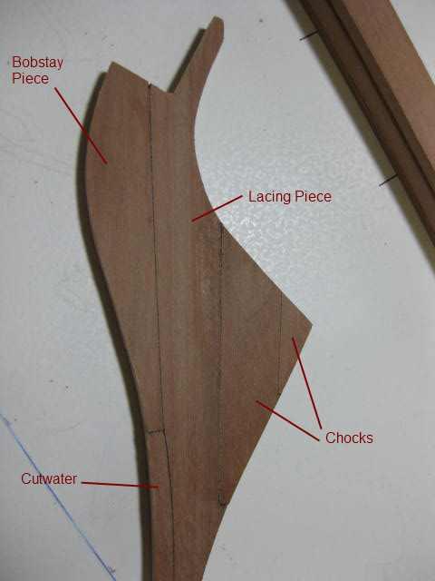
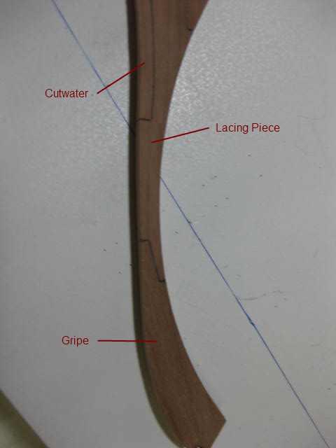
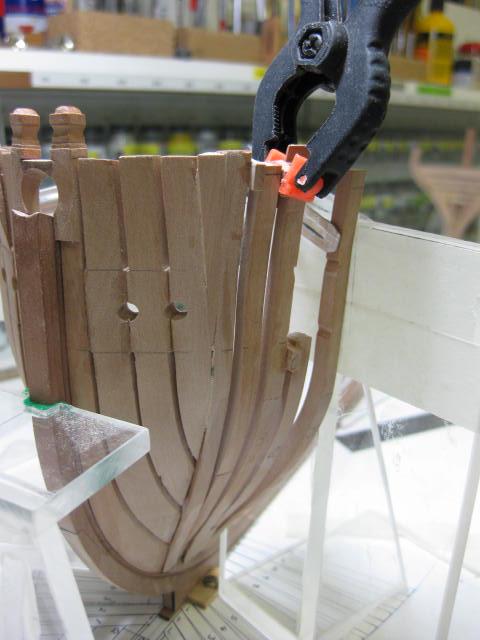
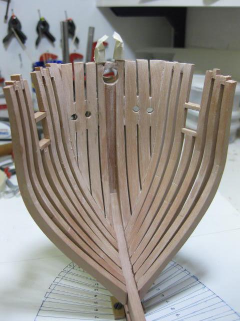
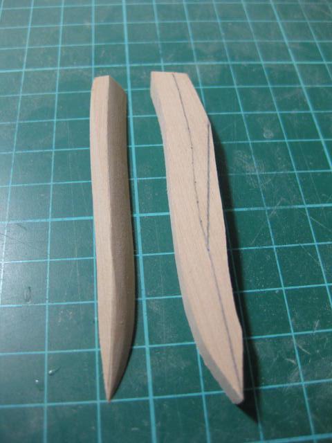
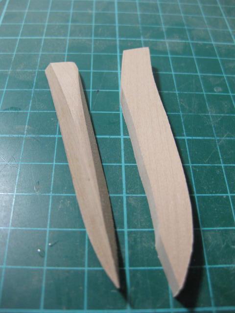
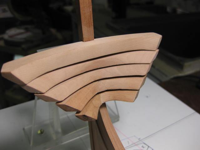
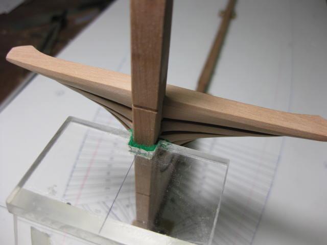
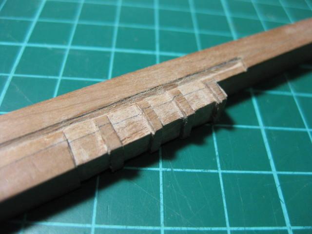
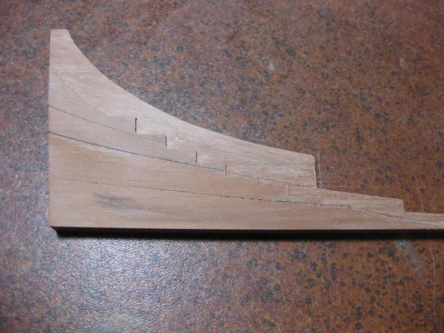
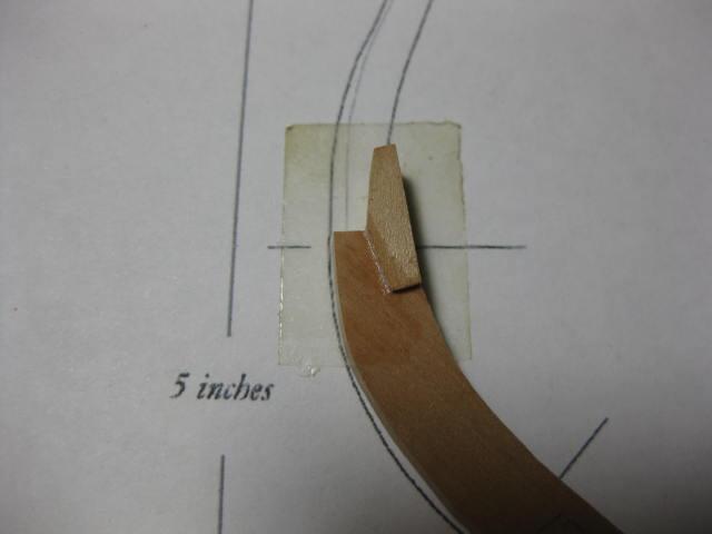
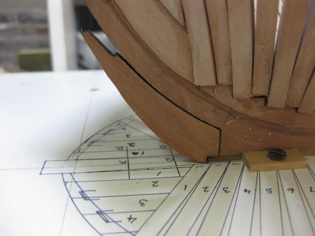
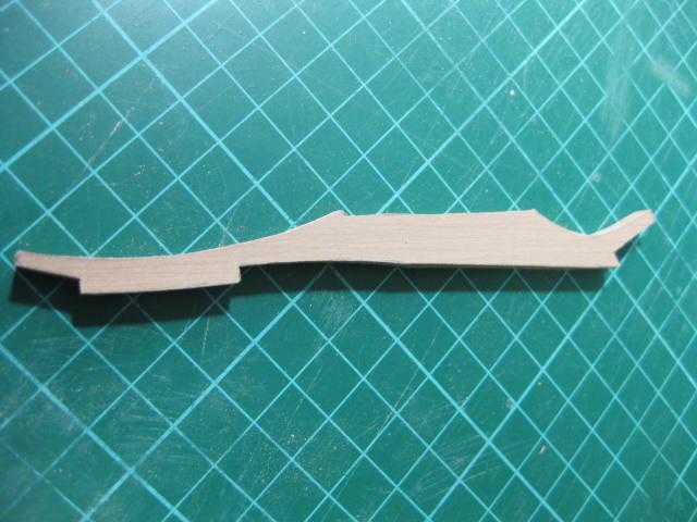
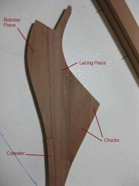
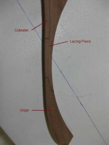
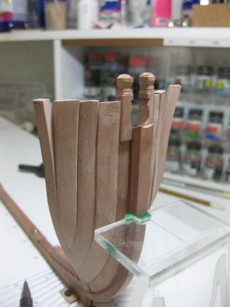
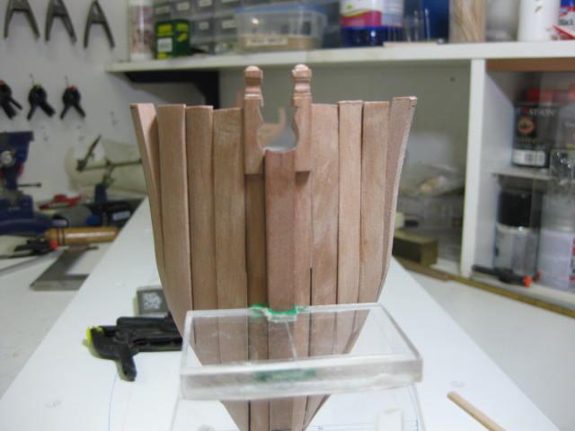
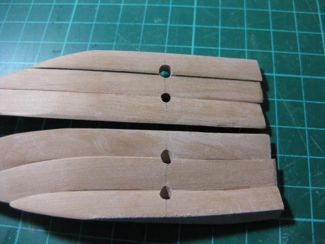
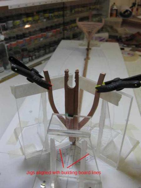
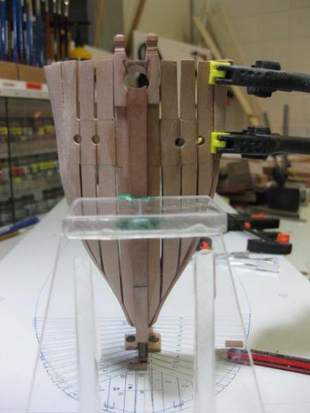
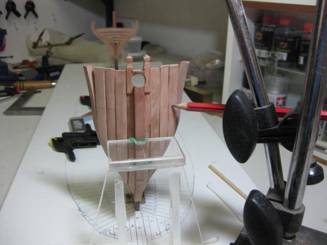
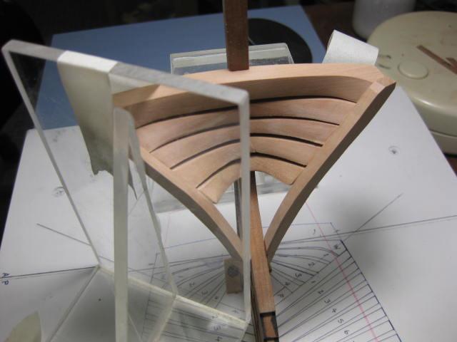
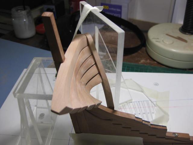
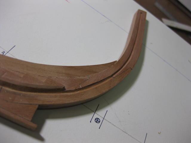
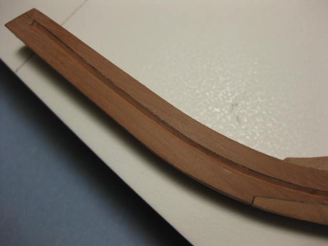
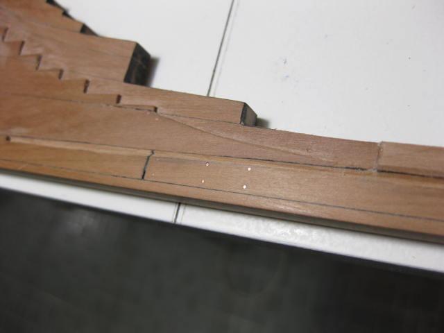
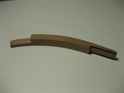
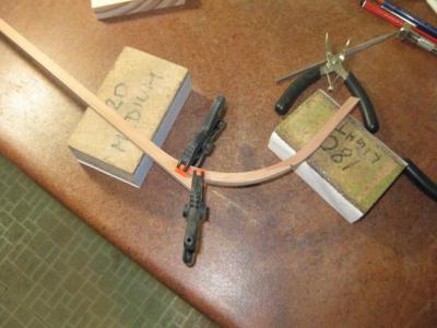
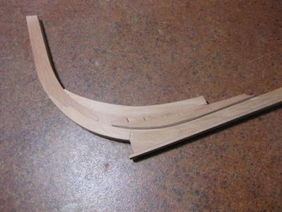
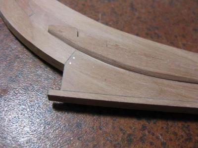
Knee of the Head Construction The Stem is constructed from eight pieces, which were through-bolted on the real ship. Construction starts with the lowest one - the Gripe. A card template of the Stem was first created, and the inner edge cut to it. This was dry-fitted numerous times until a perfect fit was achieved, then the outer edge was cut in. Much work was involved in getting a good fit to the keel joint. "Caulking" was applied with an Archival Ink Pen : Next is the most complex one - the Lacing Piece. This took about 2 hours to make. I had an accident much later in the build and snapped this piece . The full story can be found HERE . The next two pics show six of the pieces making up the Knee : The Knee tapers in both a fore-aft direction, and also from top to bottom : The two upper pieces of the Knee. The Gammoning Slot and Bobstay holes have been drilled in : Rubber Bands were used to hold the Knee while the glue dried :

-
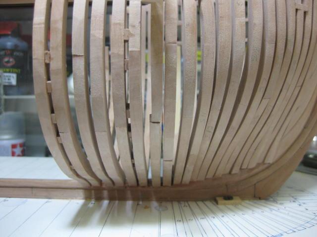
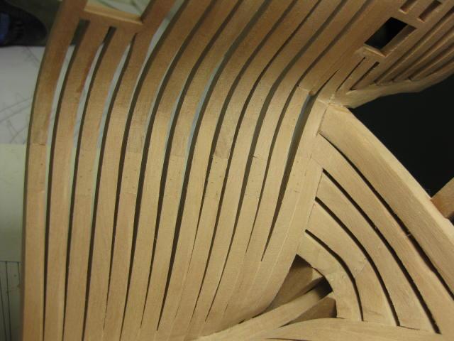
Aft Cant Fairing The inside of the Aft Section has been partially Faired. It's a lot easier to do to this stage before too many other frames are fitted. Final fairing will be done at a later stage :
-
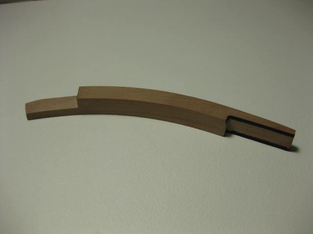
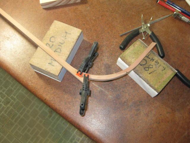
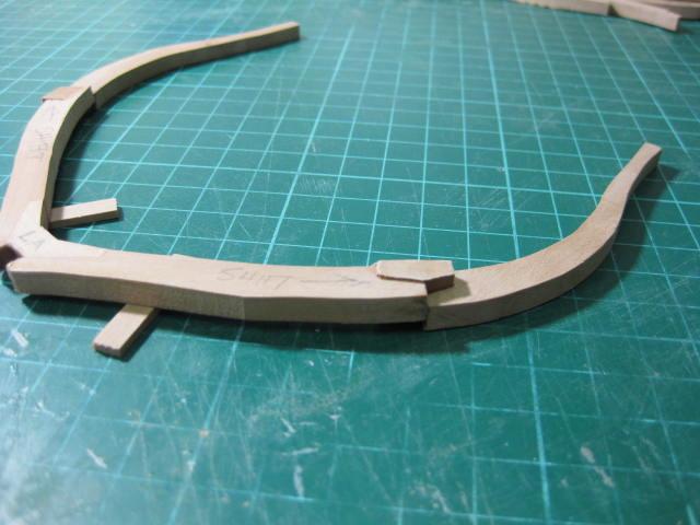
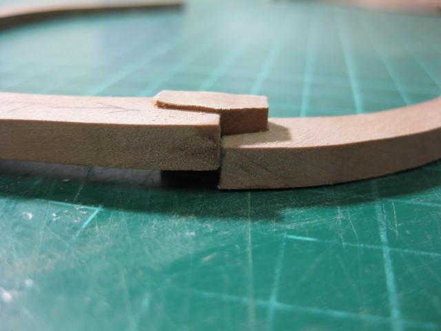
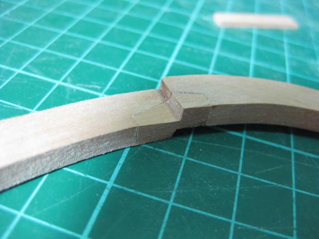
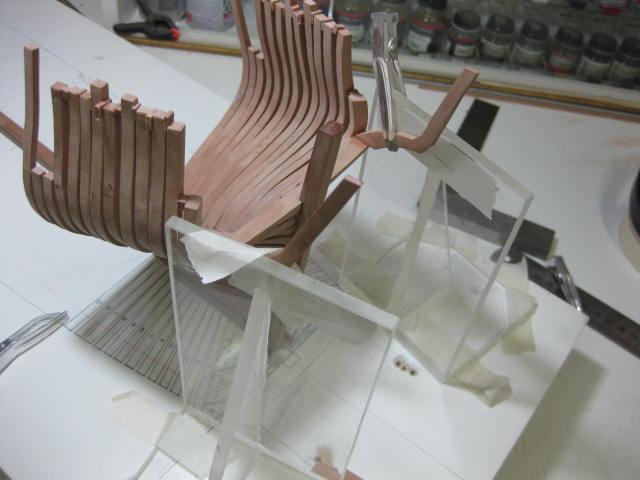
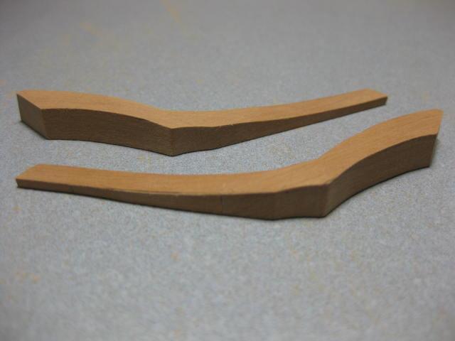
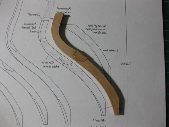
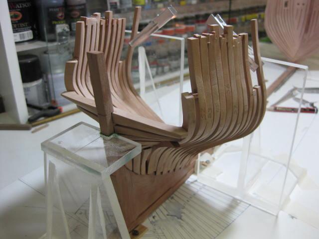
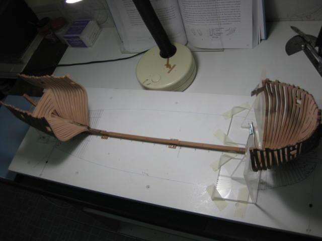
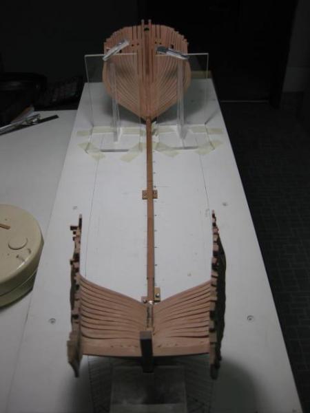
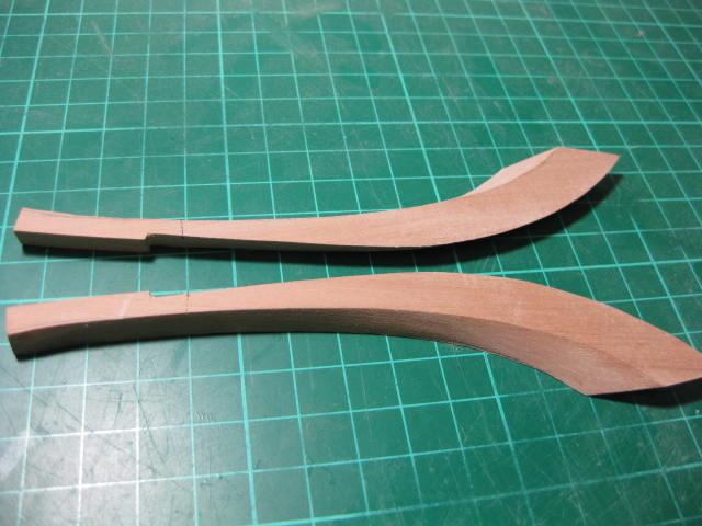
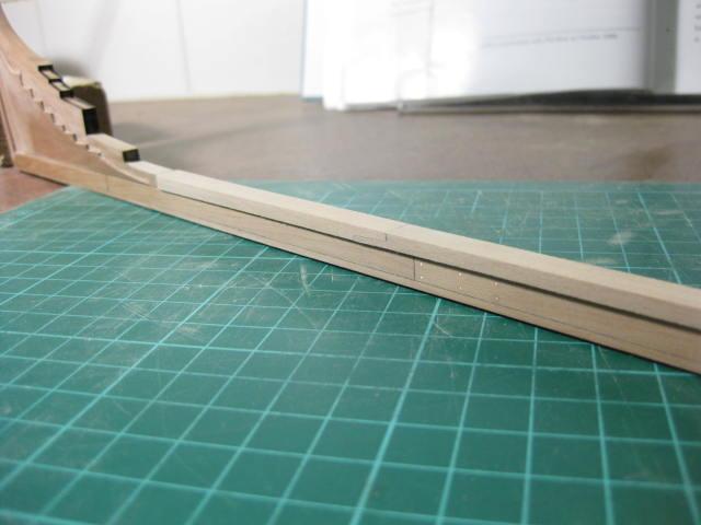
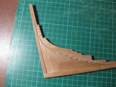
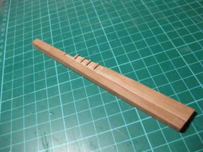
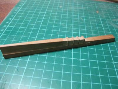
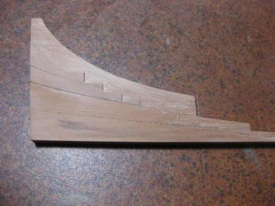
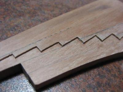
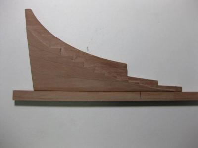
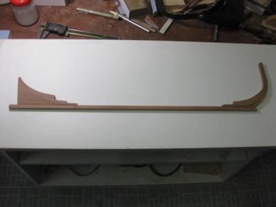
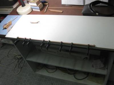
Side Counter Timbers and Timbers on the Side Counter No, I'm not repeating myself . The two names in the title are real. The Side Counter Timbers are the two pieces that extend from the Wing Transom to the Taffrail. They have a rather interesting shape : The pieces were cut from thick stock and filed to shape. The one on the left is completed, the one on the right had been shaped on one side only when this picture was taken : I used the Squaring Jigs to align them with the markings on the baseboard. They are only glued to the Wing Transom and are rather fragile at this stage : "Third Hands" were used to support the Timbers on the Side Counter while the glue dried : When the temporary spacers were glued in the whole assembly became a lot more stable :
-
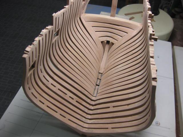
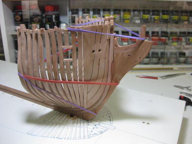
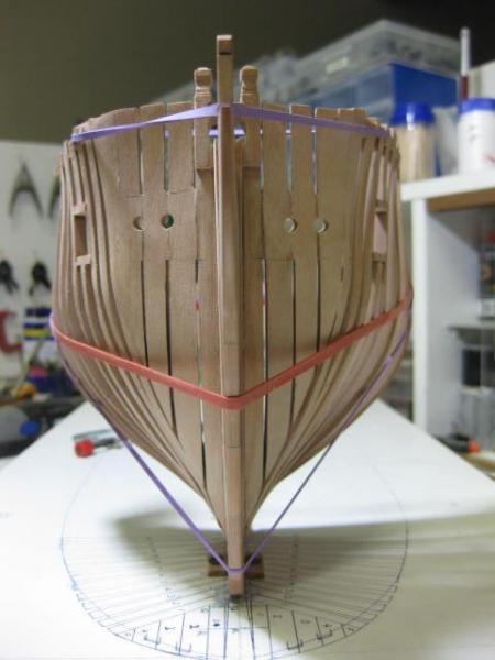
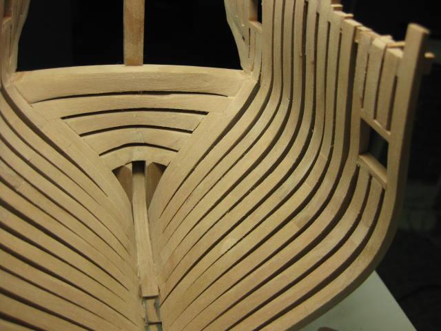
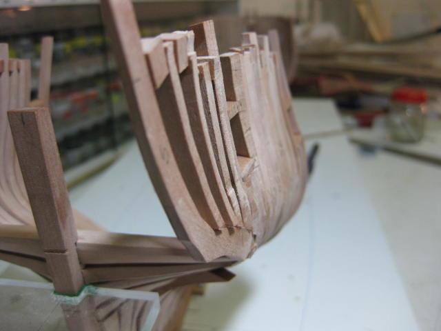
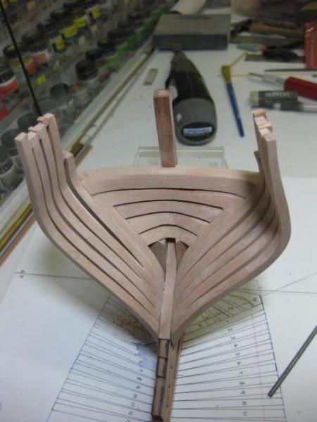
Aft Cant Frames The Aft Cant Frames are made in similar fashion to the forward ones. They sit in the steps in the Aft Deadwood : Fillers are fitted between the Fashion Pieces and Sternpost beneath the lower Transom : All the Forward and Aft Cant Frames are now fitted :
-
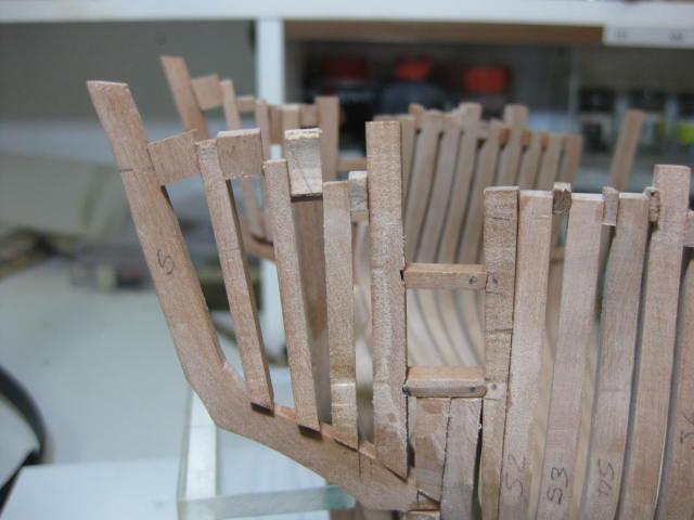
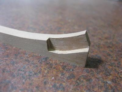
Forward Cant Frames The remaining Forward Cant Frames were now cut and assembled : Rebates were cut into the frames that side the Bridle Port. The top one has a horizontal cut in the upper end, while the bottom one is "birdmouthed" : The cant frames were all glued to the apron. Temporary spacers are glued in to hold the tops in position : The lower ends fit into the rebates in the Apron. Each pair has a reducing angle where they fit to the apron. The angles were done on the Byrnes Disc Sander using the tilting base.


-
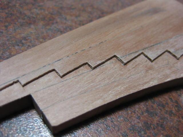
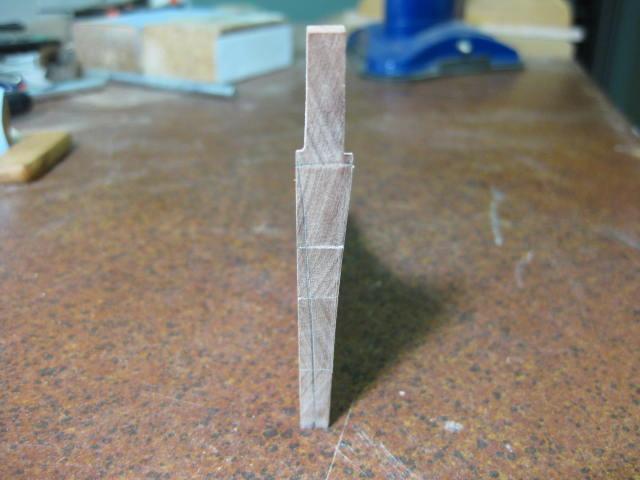
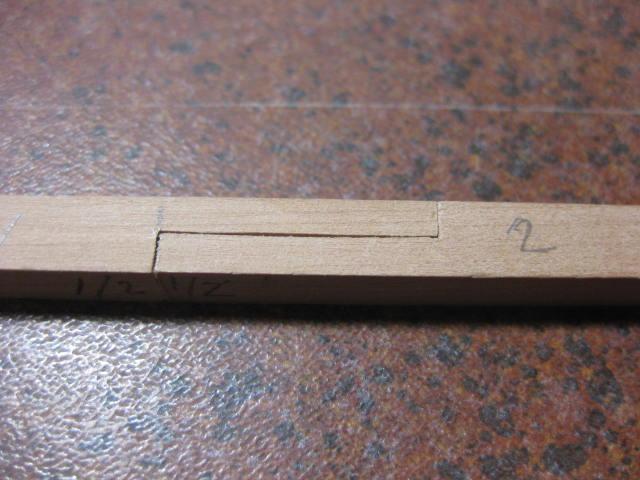
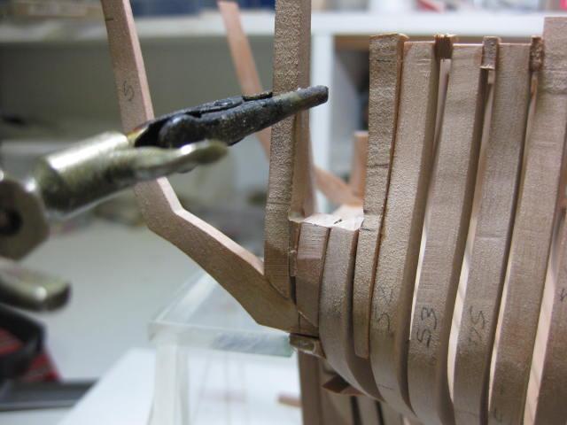
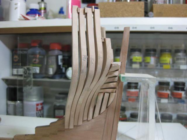
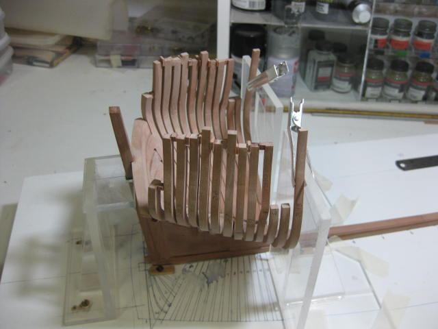
Forward Cant Frames and Hawse Timbers Before any more of the Hawse Timbers can proceed the first two Forward Cant Frames needed to be made and fitted. These were once again made from the CD patterns. They are each made in two sections, joined together by a scarfed Chock - it's almost invisible on the frames in the picture but can be clearly seen on the plan below them. As the Port side will be Fully Planked I only use the Chocks on the open Starboard side - the Port side just gets a simple scarf joint : The two Cant Frames are now fitted using two Squaring Jigs aligned with the markings on the baseboard : The Hawse Timbers are now cut and bevelled, and "spot-glued" into position - there is still a considerable amount of work to be done on them before final fitting : The positions for the Hawse Holes are now marked using an adjustable Height Gauge. The Mylar Side Elevation was glued to a piece of board with the bottom of the keel flush with the bottom of the board and mounted vertically to the wall behind my workbench. The height gauge was then set up directly off the plan : The assemblies were then removed from the hull and the hawse holes drilled and filed to an "under-size" which will be enlarged later in the build : The Air Gaps (ventilation to stop the timbers rotting) were cut between the hawse timbers and the assemblies permanently glued in :


-
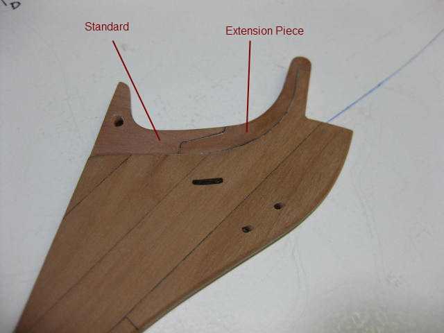
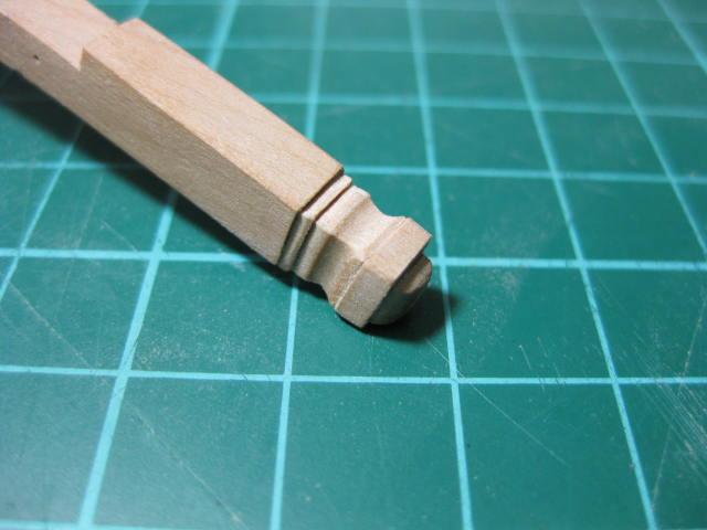
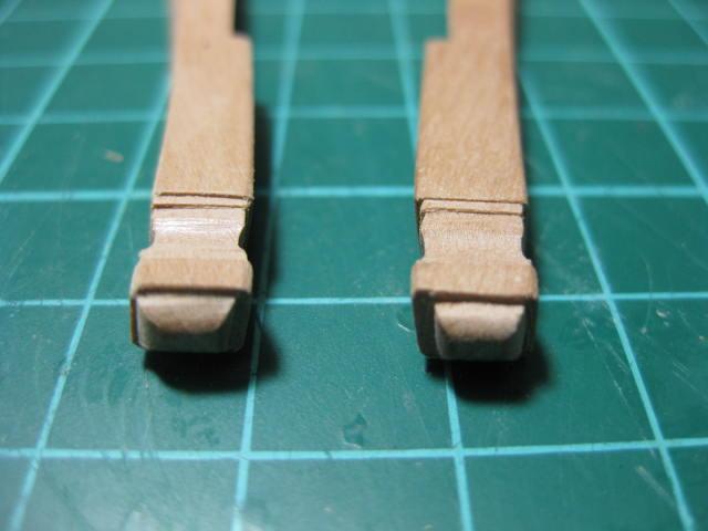
Timberheads and Bowsprit Chock The Bollard Timbers are topped with "Knightheads" - decoratively carved tops that were used for fastening some of the forward Running rigging. I carved these with an Xacto knife and round needle file : Next I "spot-glued" the Bollard Timbers to the stem and cut the opening for the Bowsprit into them. This was finished off with the same sliding sanding tool I used for the step in the top of the stem : The Bowsprit Cross-Chock is a deceptively difficult piece to get right due to the many different angles involved. The picture below shows it just after fitting - it hasn't been fully trimmed to match the surrounding timbers yet :
-
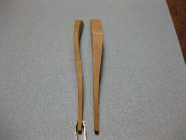
Bollard Timbers The two Bollard Timbers attach either side of the Stem, and are the first of the Hawse Timbers which make up the forward part of the hull framing. These were marked out from one of the patterns supplied on the CD and bevelled and tapered to the patterns - not a good idea, as they finished up fractionally small once again but not enough to be a major concern.

-
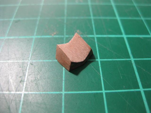
Fashion Pieces The first pieces of Hull Framing are known as Fashion Pieces. They fit to the ends of the Transoms and attach to the Keel. These were cut from the profiles on the CD in similar fashion to the transoms. I cut them to the FULLEST part of the profiles, ignoring the tapers, the SECOND time around. The first time I attempted to make them to the taper shown on the profiles with poor results - when I fitted later frames they were TOO SMALL and had to be re-done. A hard lesson learned . I used my smaller Squaring Jig to fit them :
-
Cutting the Bowsprit Seat The Bowsprit Seat was cut in next, using a straight piece of brass round which was taped to the "convergence point" where the bowsprit would intersect the keel if it continued that far. This point is marked on the Mylar TFFM plan, and coincides with the NMM plan. 120 grit sandpaper was glued to a piece of brass tubing of the correct diameter. This tubing was an easy "slide fit" over the brass round bar. The sandpaper "carriage" was moved back and forth on the upper part of the Stem until the Bowsprit Seat was at the correct depth :

-
Cutting, Shaping and Fitting Transoms The five Transoms were marked by first applying each profile that had been printed onto the Label Paper from the CD. An Awl was used to mark the limits of the tapers : Each transom was then shaped to a generous "oversize" using chisels and sanding blocks. The rebates for the sternpost were cut : The transoms were then glued to the sternpost, making sure they were both in line with the marked baseboard and also parallel to it at each end :


-
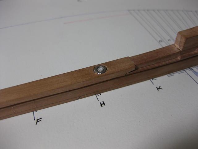
Cutting Rabbets and Fitting the Mounting Nuts A Rabbet was marked and cut the length of the keel using a "V" gouge and Xacto blades. The rabbet gradually changes angle at approximately the start of the Deadwood to accommodate the change in angles of the planking : Stainless Steel Mounting Nuts were now fitted into the Keel for the screws that hold it to first the Baseboard, and later the Pedestals : The Keel was screwed to the Baseboard :
-
Rising Wood The Rising Wood sits atop the Keel. In reality it is rebated to accept the Frames - it's easier to rebate the frames themselves as the joints look the same either way :
-
Sternpost The Sternpost is laminated from two pieces. It has some rather interesting rebates cut into it to receive the Transoms and the Planking :

-
Aft Deadwood The Deadwood afore the stern is made from five pieces of timber. These are bolted top to bottom in the real ship - the bolts are up to 14 feet long. They have similar rebates to the Apron for the lower ends of the Frames. The Deadwood is an area that has differences to the TFFM plans : The Deadwood is tapered from top to bottom. In this pic the Starboard side has been done and the Port side is marked in readiness :

-
Stem and Fore Deadwood The Stem is made in two sections, with a Scarf Joint between them. The Boxing Joint between the lower part of the stem and the Apron has also been cut in. Note the 90 degree orientation of the two joints : The upper and lower parts of the stem have been glued together. Here they are being fitted to the Apron : The Fore Deadwood has been fitted : Copper wire "bolts" have been fitted through the Boxing Joint and the Scarf Joints along the Keel : Finally, the Stem was tapered from top to bottom, and also in a fore-aft direction : The upper part of the stem is slightly different to TFFM on the NMM plans.
-
Lower Apron This is one of the hardest pieces to construct in the whole ship. The whole Fore Frame Assembly relies on the accuracy of the frame rebates. There was also considerable work involved in shaping the Boxing Joint to fit the Keel :

-
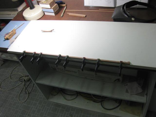
Laying the Keel It's finally time to make some sawdust . Work begins with the Keel. The fore part of the main keel uses a Boxing Joint to fit up with the Apron : The Keel itself is made in four sections. Each has a Scarf Joint : I clamped the keel to the edge of my Building Board to ensure it was straight while the glue dried :
-
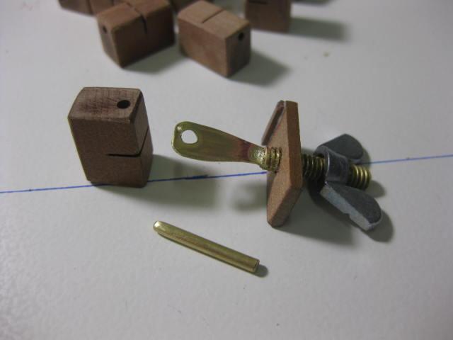
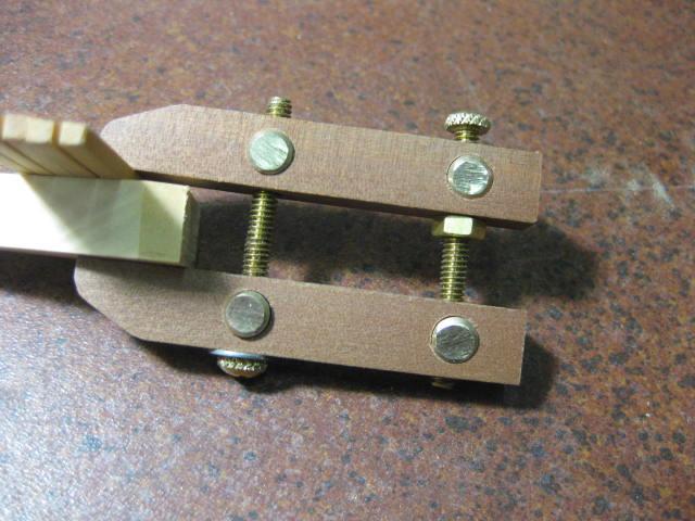
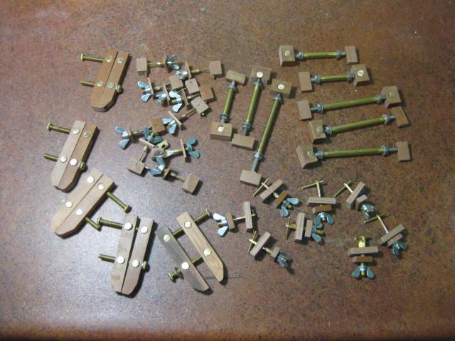
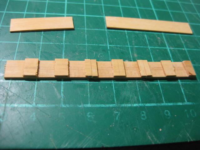
Clamps and Planking Pins I made 16 clamps of this type. They are used primarily for clamping Planking where the clamp can fit between two Frames : These Clamps are very useful inside a Hull, mostly used for Planking again. I made 12 of them also : The (6) Parallel Clamps hold pieces together without pulling them out of line like normal Spring Clamps tend to do : An overview of the first batch of Clamps I made - I added some more of each type after this pic : One day soon I'll post a "How To" make the various Clamps in the Modelling Tools Forum. I also made 12 Planking Pins. These use a 0.5mm pin, which is the size of most of the Treenails used on the model. They come in handy where I need to use a Pin directly through a Plank etc :


-
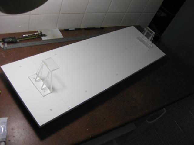
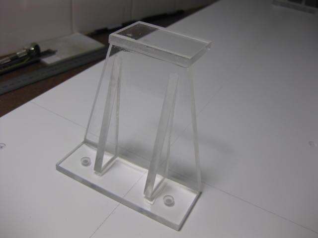
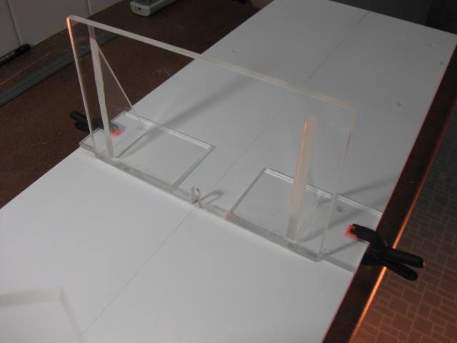
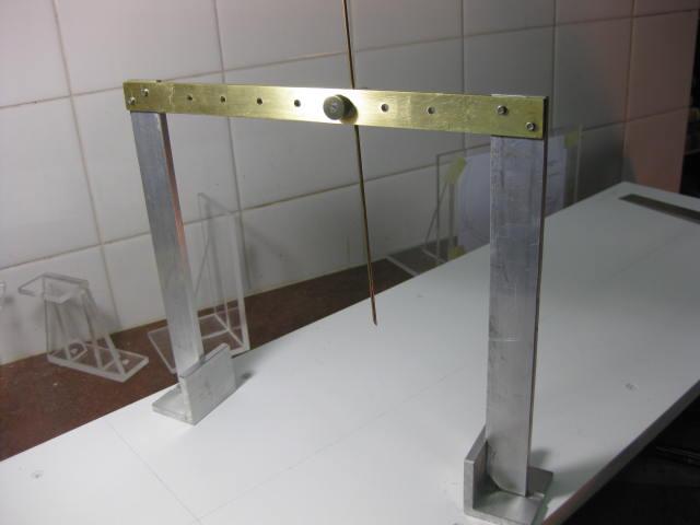
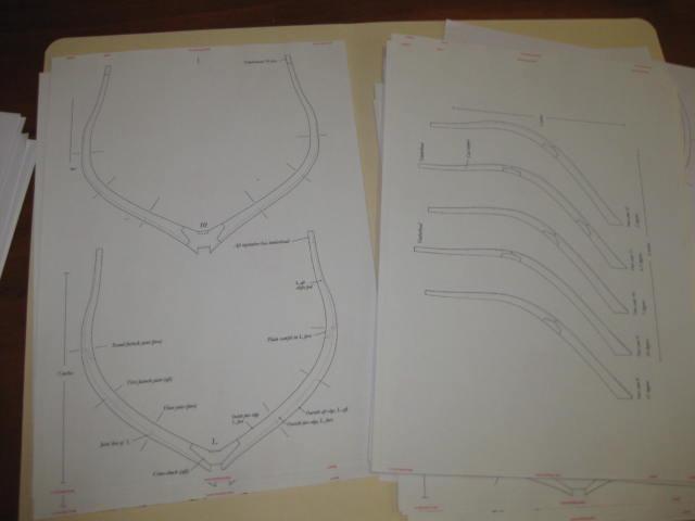
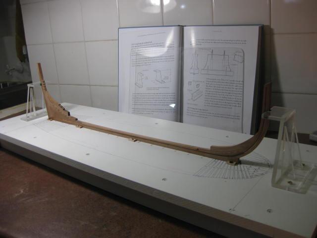
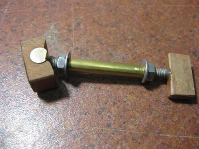
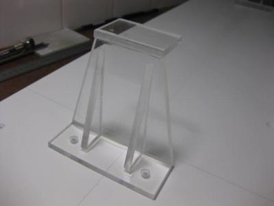
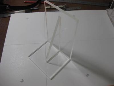
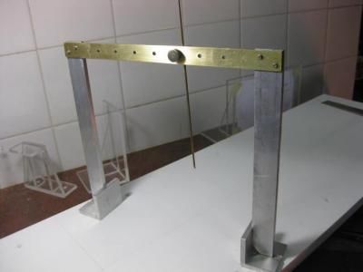
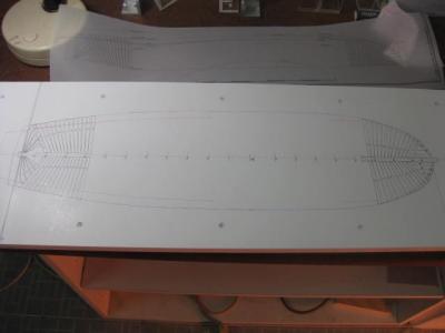
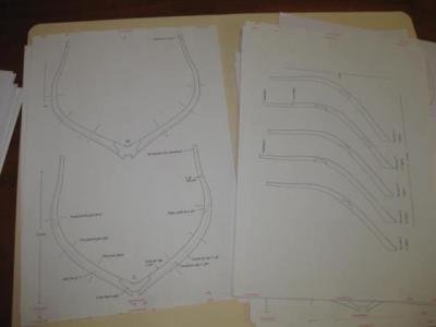
Preparations Before any work commenced on the model there were some other things to build. Using the directions in TFFM I constructed a Building Board : I added Supports for the Keel, fore and aft, from clear Acrylic (Perspex) : I also made two Squaring Jigs for the Cant Frames and one for the Square Frames : I made a Jig to measure up from the Baseboard that can be used inside the Hull : The Baseboard was marked for the Plan View using a tracing of the Mylar Plan : The Frame Profiles were printed from the Admiralty Models CD onto A4 size "sticky-backed" Labelling Paper :


-
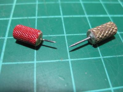
Tools I have been building wooden ship models for over 30 years, and in that time I have accumulated quite a large collection of Modelling Tools : Numerous Xacto Knife handles of three sizes - it saves a lot of Blade changing. Hundreds of Blades for these, both Stock and Modified. Same with Pinvices - I have four Handles fitted with the most commonly used size of drill bit. Several boxes of Minidrills plus larger sizes in both Inch and Metric. A Swivel Vise - no serious modeller should be without one. Also a couple of sets of "Third Hands". Razor Saws, both "push" and "pull" cuts - two handles plus many blades. Some of the blades have been ground down to enable cuts in very tight places. Dozens of Clamps of every description - you can't have TOO MANY of these. Cork Sanding Blocks, some modified to sand inside curves. Home-made Sanding Sticks of every shape and size imaginable. Various shapes of Mini Pliers. Various Needle Threaders for Rigging. A Jim Byrnes Drawplate for making Treenails. Now the "fun" bits - the Power Tools : A Sherline Long Bed Lathe A Sherline 8-axis Mill. A Digital Readout for both Lathe and Mill. Nearly every Accessory for both the above. Jim Byrnes Table Saw, with all Accessories. Jim Byrnes Thicknesser. Jim Byrnes Disc Sander. An ancient Dremel Scroll Saw, modified with an almost Zero-Clearance Base Plate. Still going strong 30 years later . EDIT - I recently purchased a 18" Carbatec Scroll Saw as the Dremel finally gave up. A small Taiwanese Drill Press - cheap, but quite good quality. Three Dremel Tools, one is Cordless. A Proxxon Mini Engraver. A Proxxon Mini Bench Grinder for sharpening drills and other tools. You CAN successfully build a model with the "bare necessities" of hand tools, but there's nothing like a GOOD QUALITY Power Tool to make numerous items of the same shape and size. The precision they give you when cutting timber or metal is also very difficult to match by hand.