


Dan Vadas
-
Posts
3,261 -
Joined
-
Last visited
Content Type
Profiles
Forums
Gallery
Events
Posts posted by Dan Vadas
-
-
1 hour ago, Jim Lad said:
Thanks Steven and Danny. I hope you also noticed 'Stag' and 'Frances Pritt' on the shelf, Danny!
")
John
Of course
 . Unfortunately there were NO modellers in attendance while we were there - I was expecting to see Richard as his model was on the bench.
Danny
-
Thanks Pav. The card is actually held down with very thin double-sided tape, not glued.
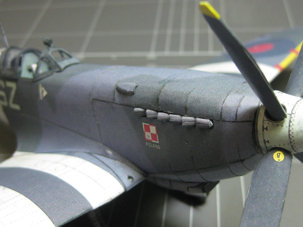
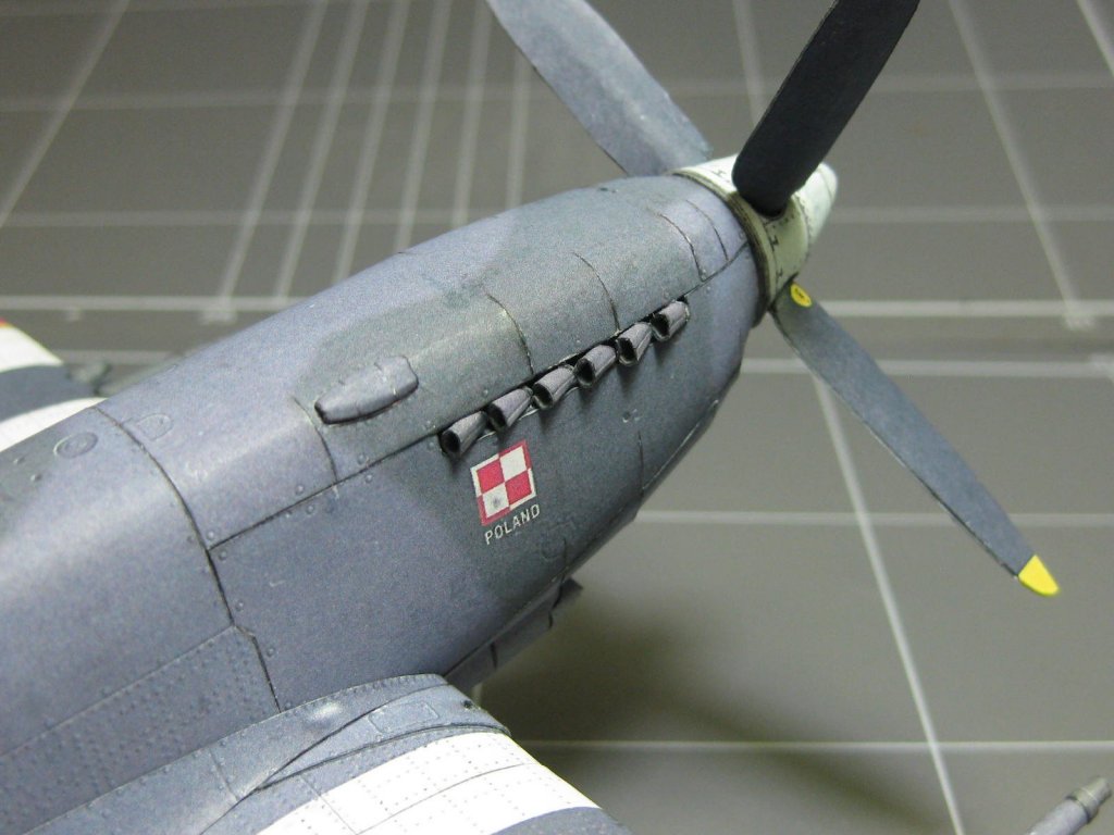
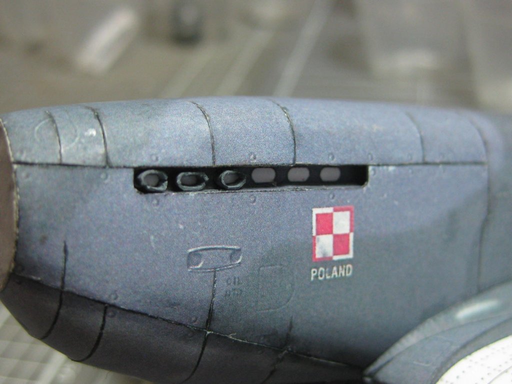
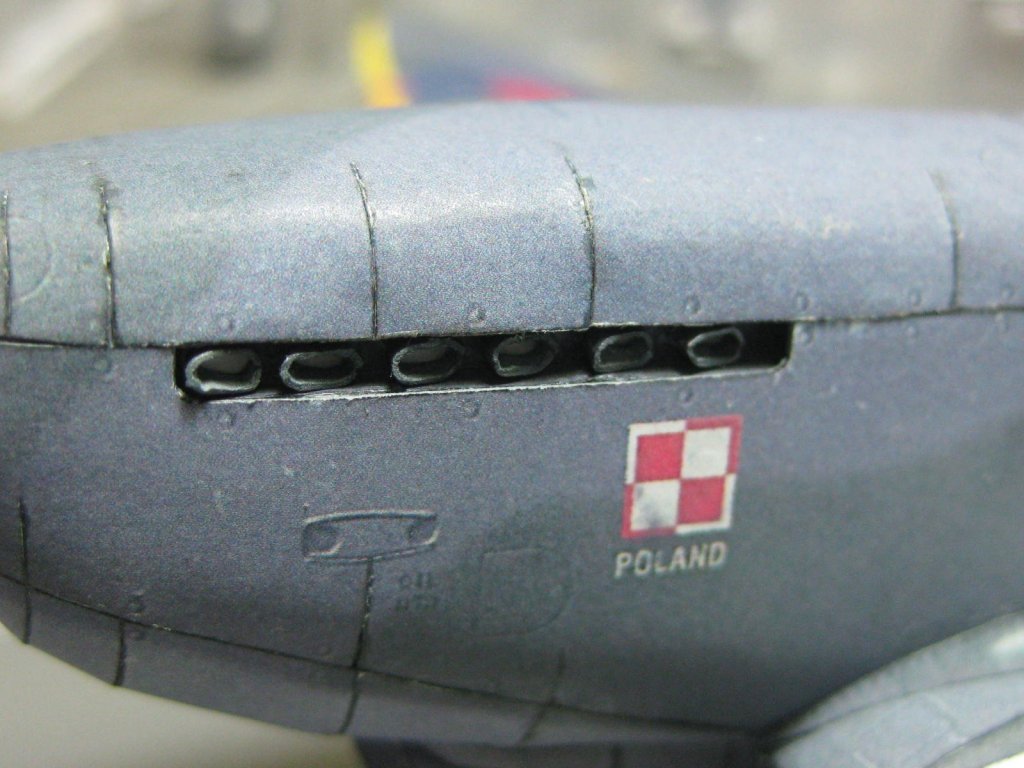
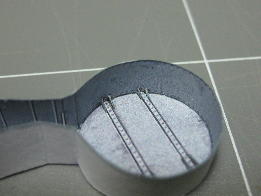
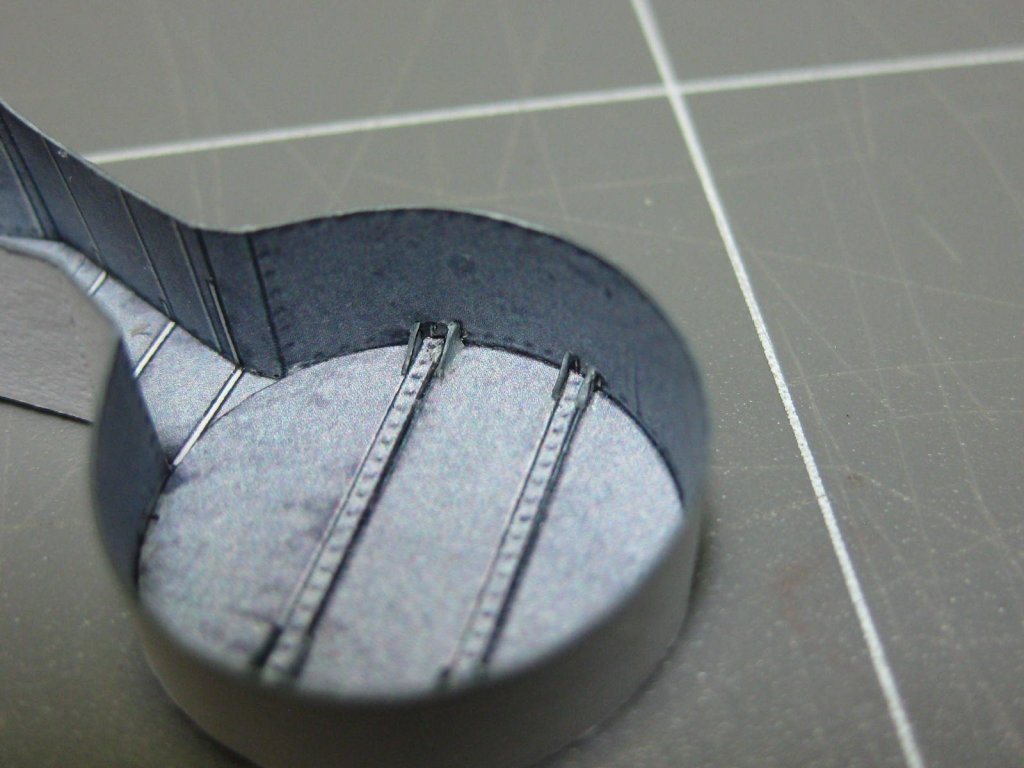
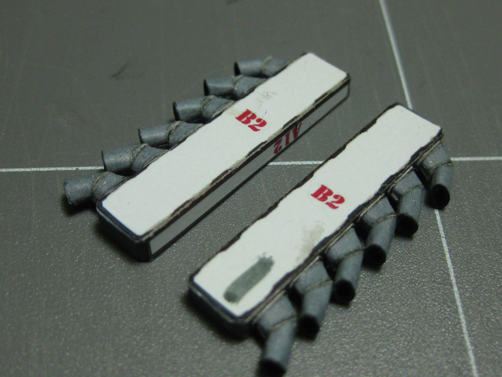
The rocker covers :
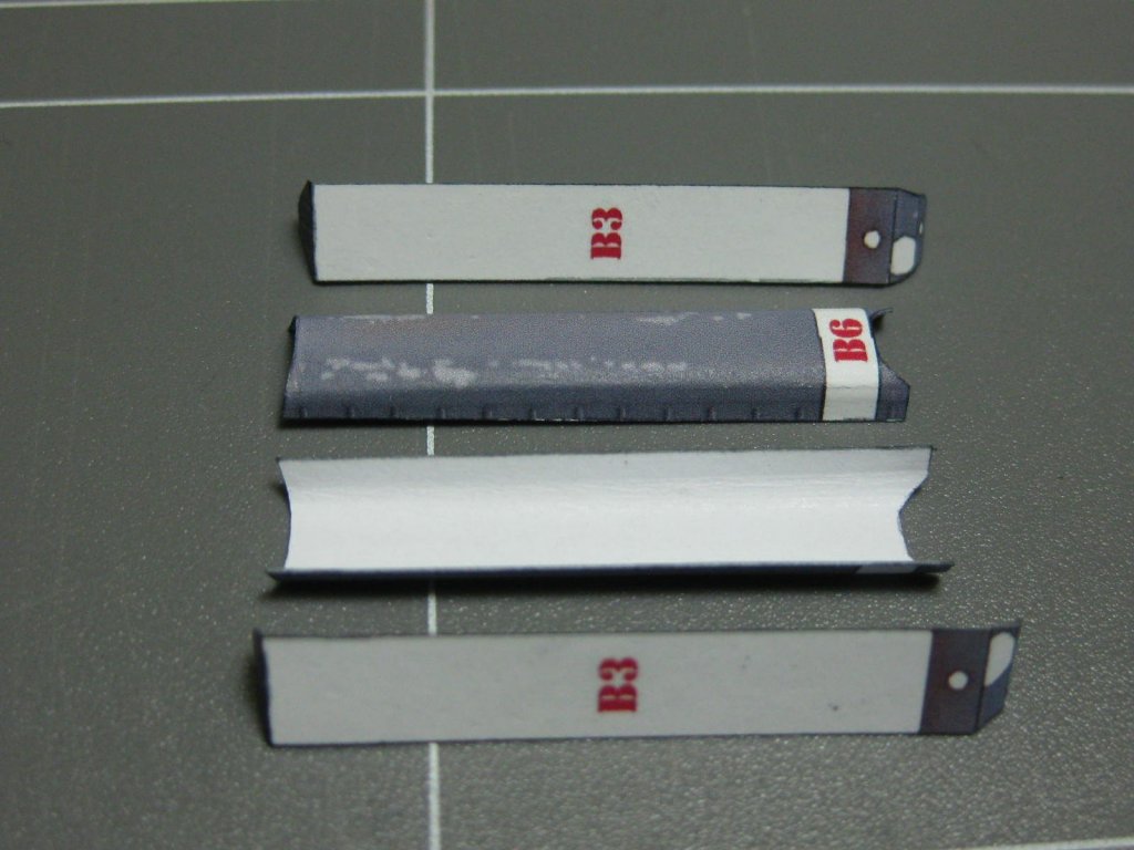
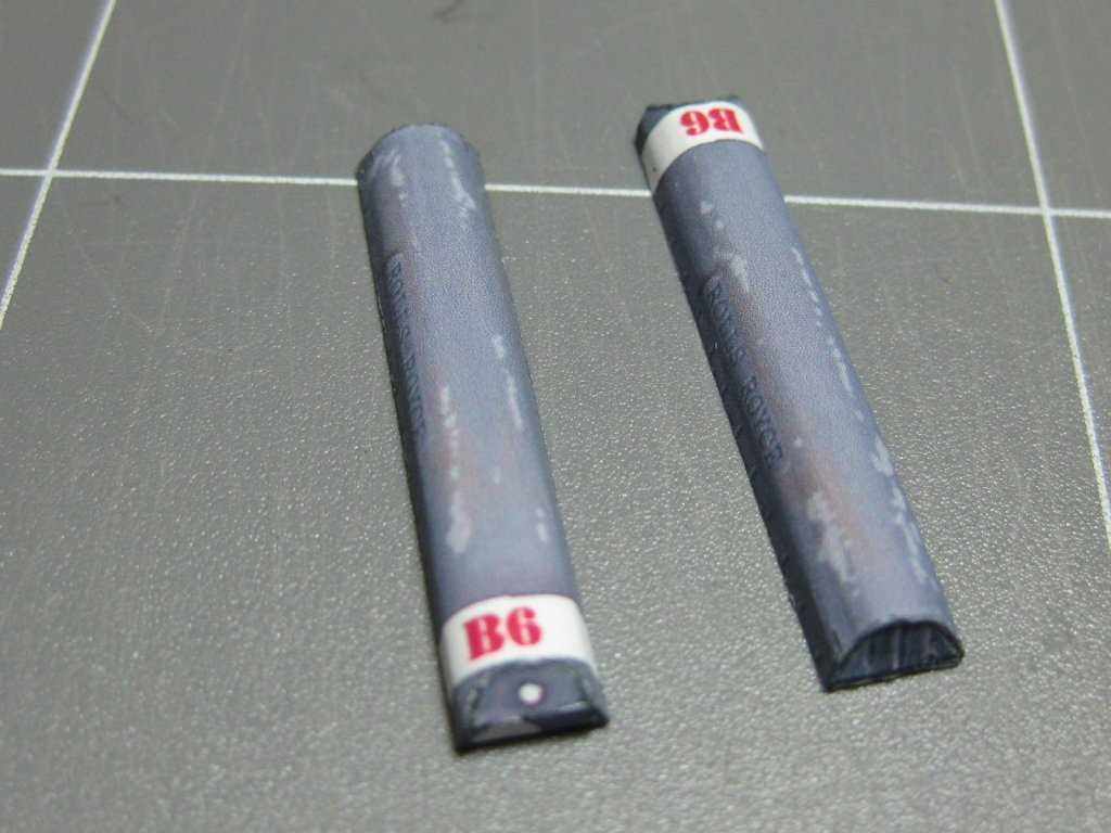
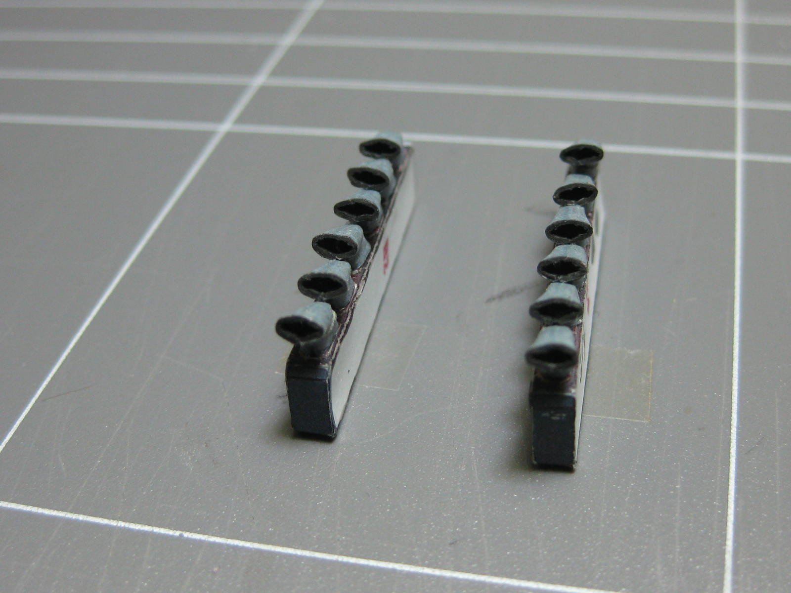
There were no exhaust pipes with the kit so I printed out the ones from the Spitfire. These took me two days to make, but I'm very happy with the way they turned out
:


Danny
- ESF, marktiedens, JeffT and 13 others
-
 16
16
-
6 hours ago, ccoyle said:
Beautiful, Doug! If you widen the search for finished models to include Pegasus, then there are actually a fair number of finished Swan-class vessels here.
Cheers!
Throw in Toni's Atalanta and my Vulture and the number of Swans gets even bigger, although neither are kits
. Great job .
Danny
- Martin W, billocrates and Dfell
-
3
-
5 hours ago, Louie da fly said:
Beautiful work, John. This build is a pleasure to follow. I'll have to find an excuse to come up and see the modelmaker's bench in operation in Sydney . . .
Steven
Ditto to the above John, except that I was actually at the museum last week and saw Meteor in the flesh
. Unfortunately it was on Friday and you weren't there  .
.
Danny
- FriedClams, mtaylor, druxey and 2 others
-
5
-
Thank you for all the comments and "Likes"
.
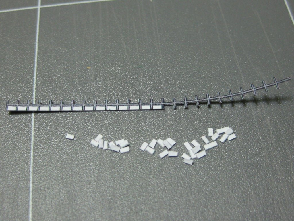
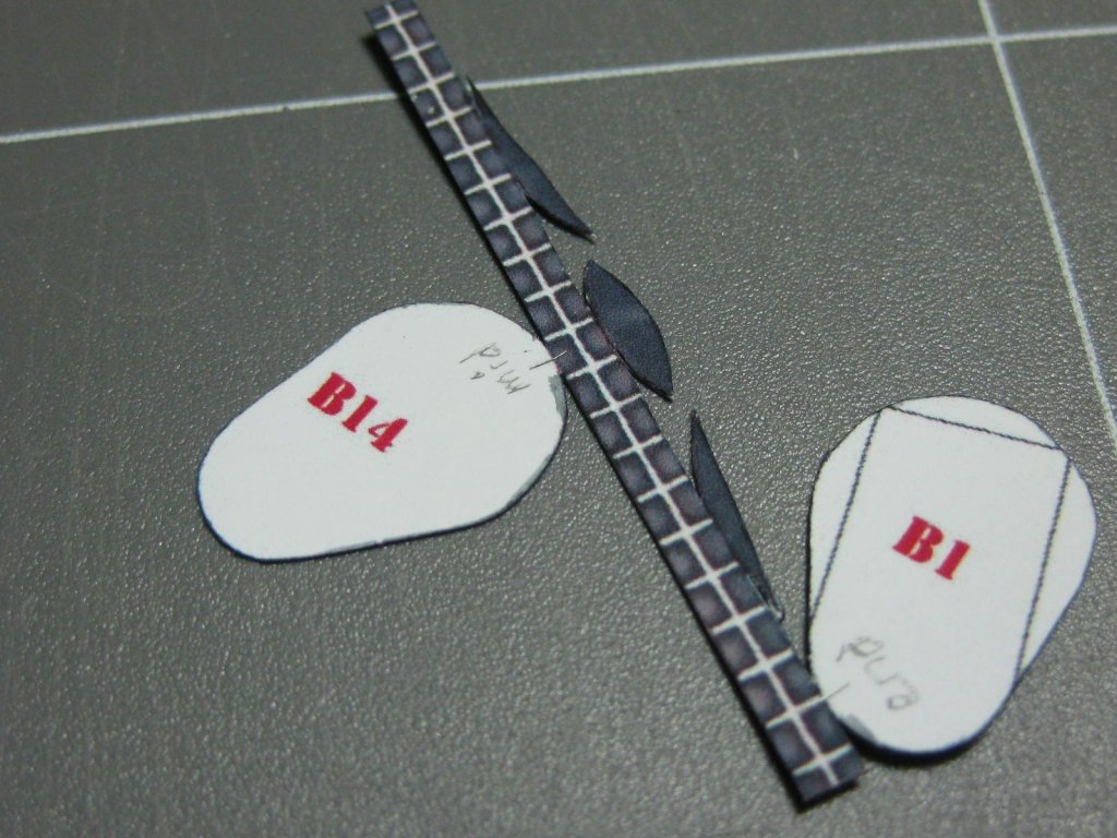
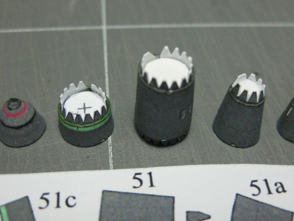
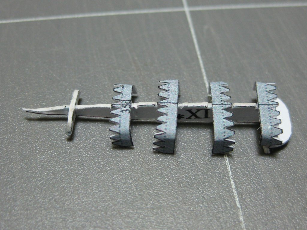
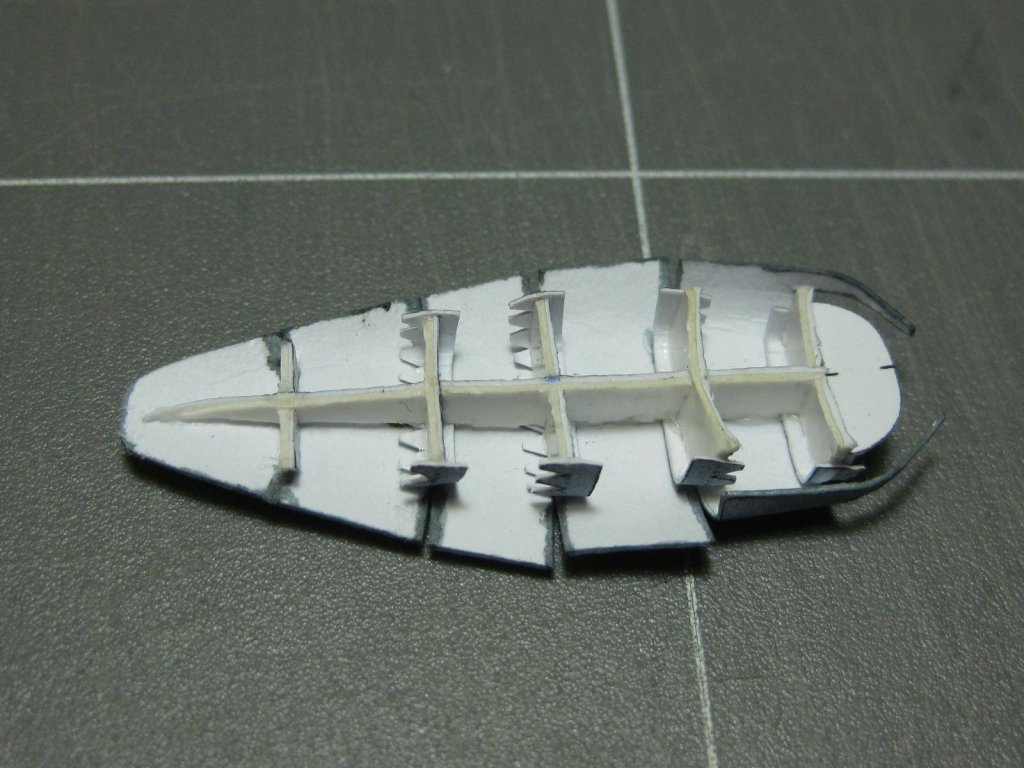
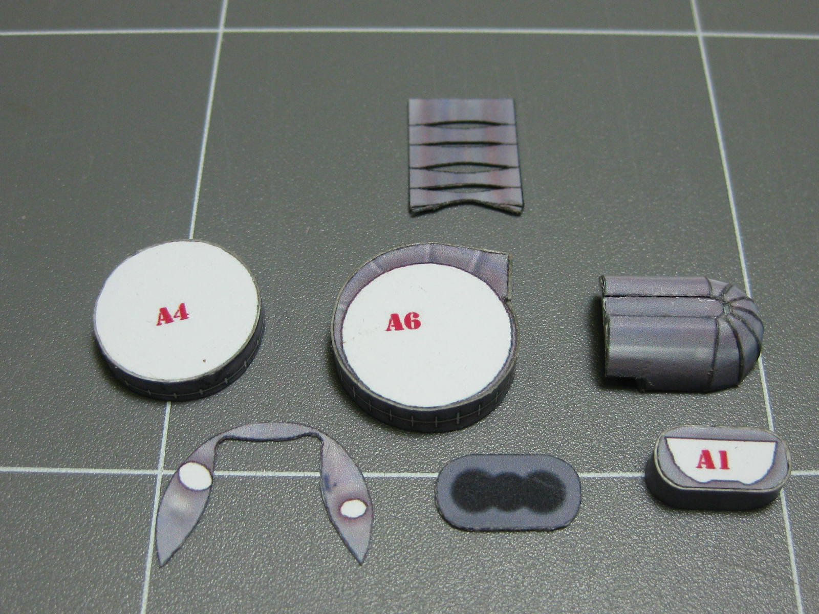
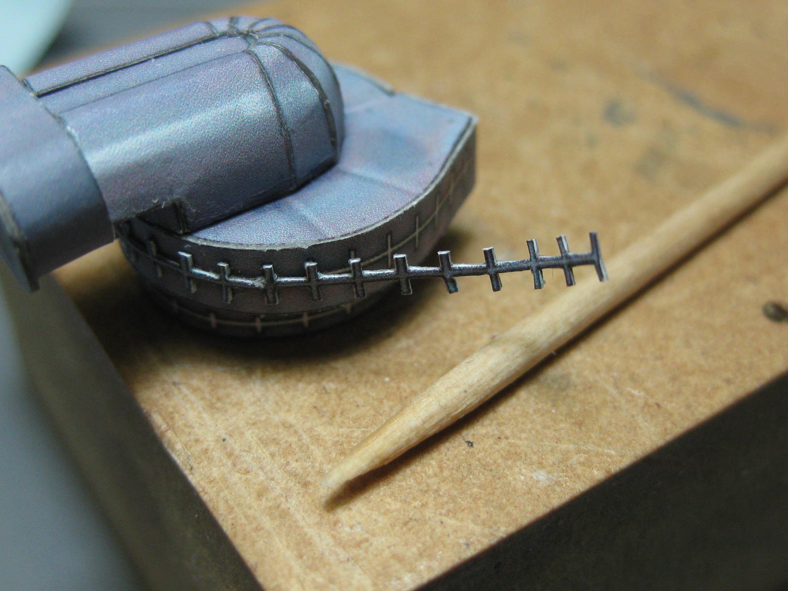
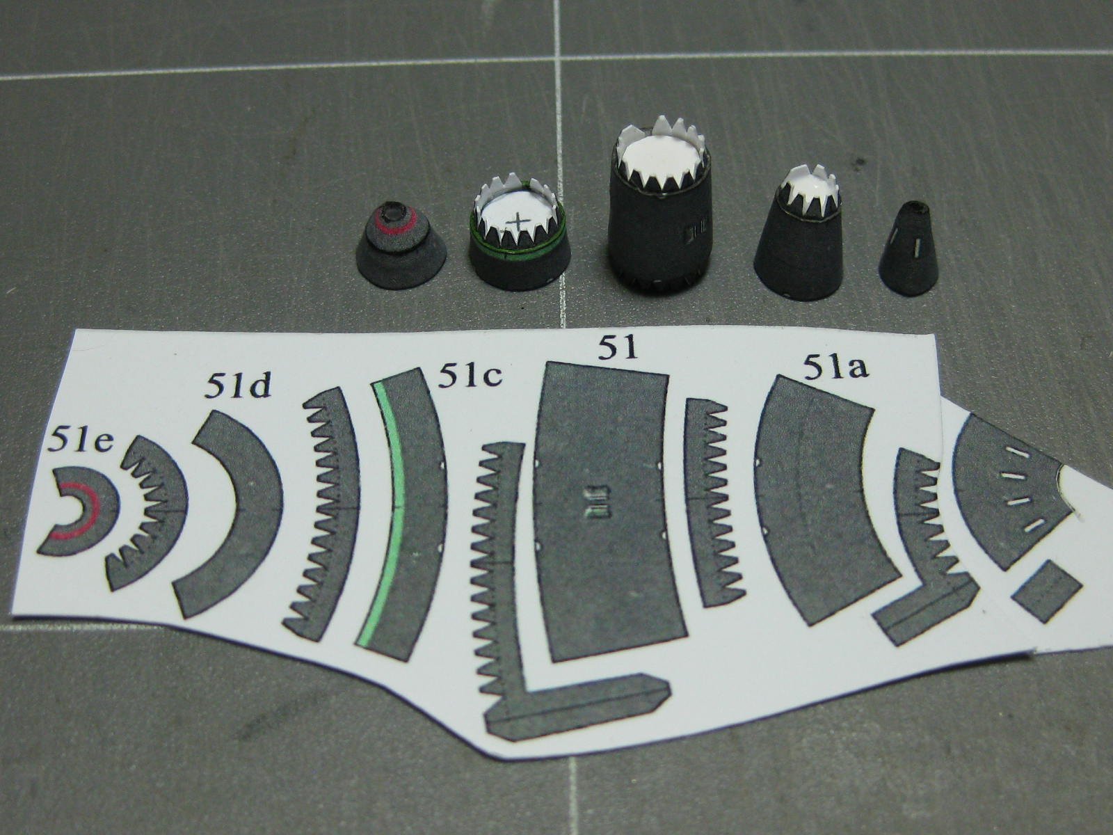
The first part of the engine in the instructions is the Supercharger. I've nearly completed it below :
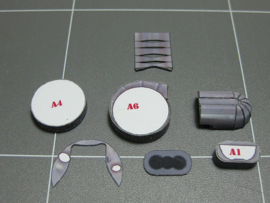
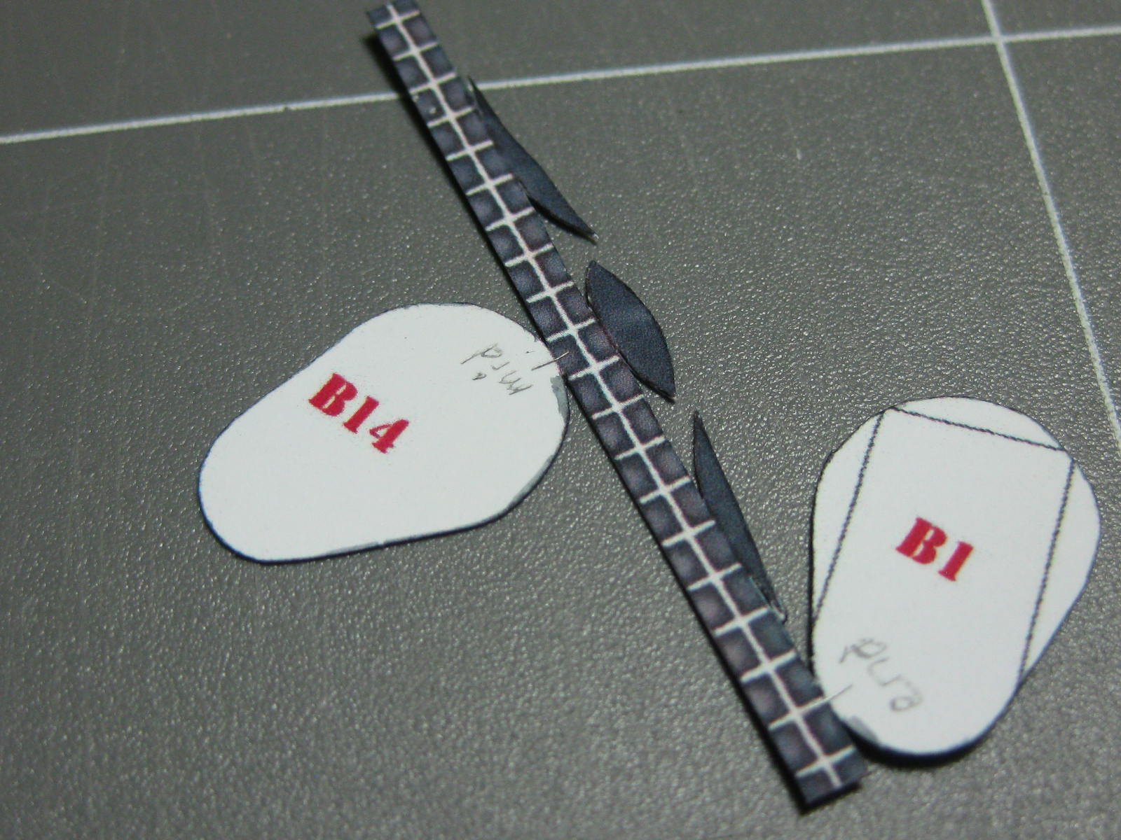
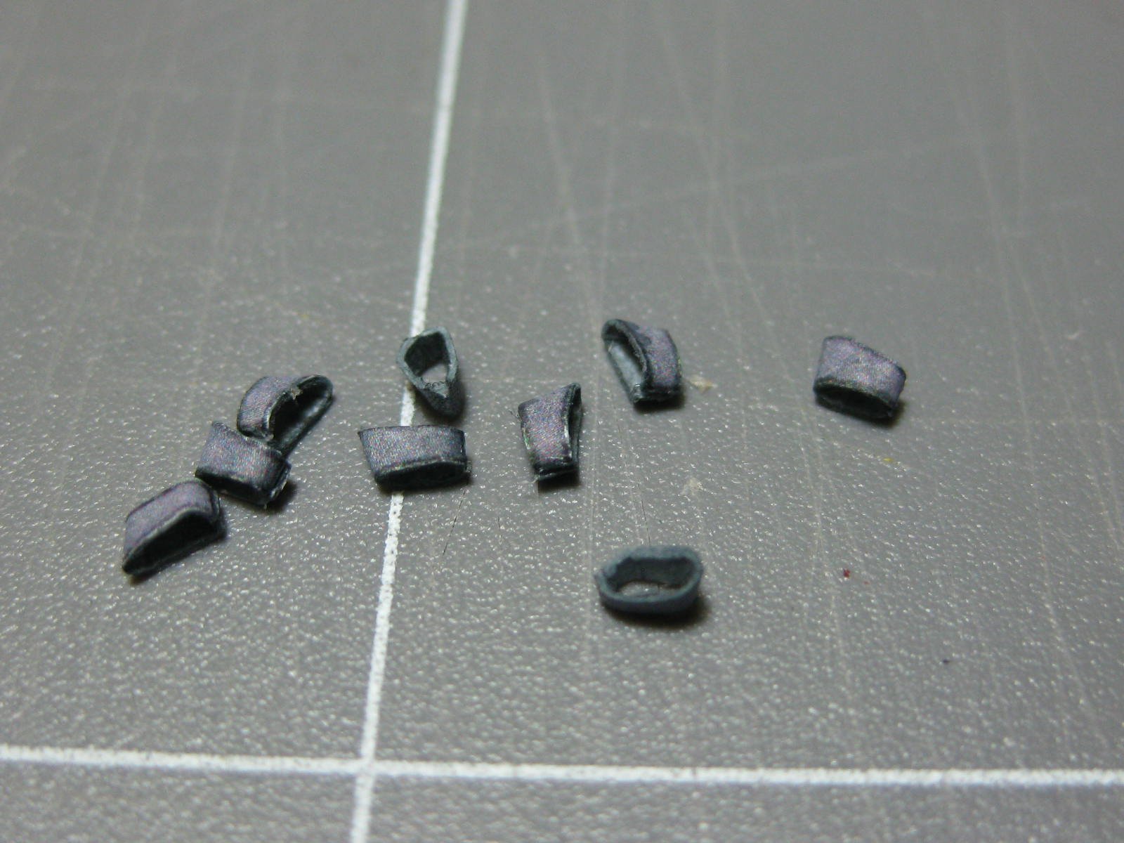
These parts took me a while to cut. So far I've come across four similar ones, all turned out fine with no accidents despite some of them being only 0.35mm wide :

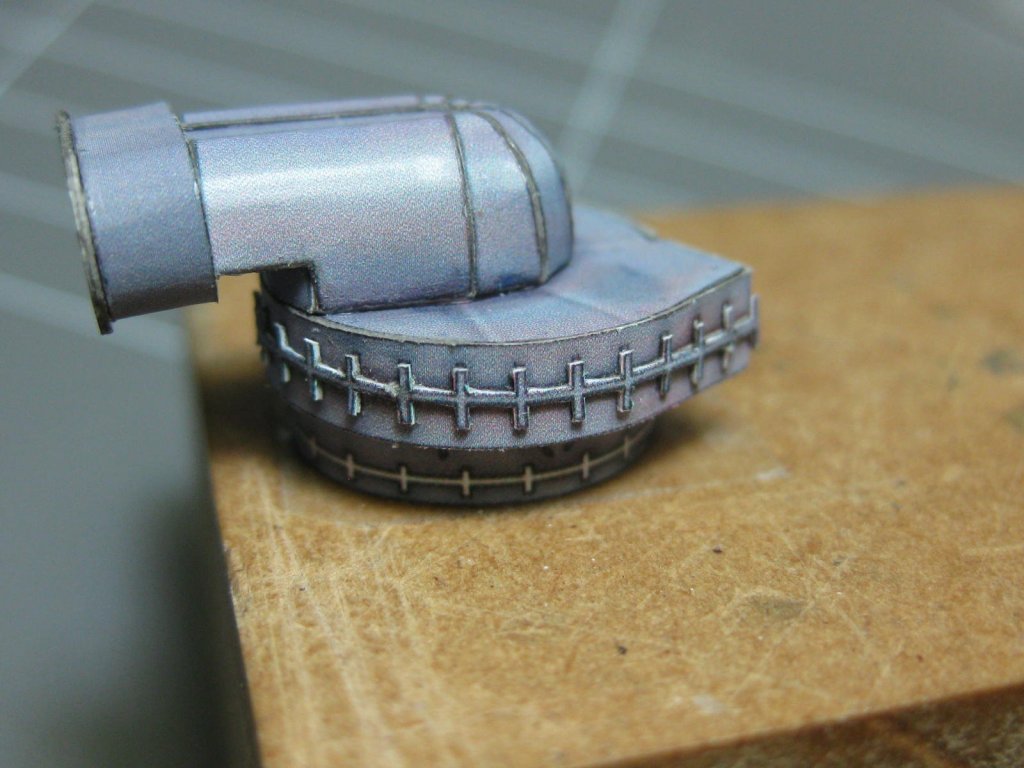
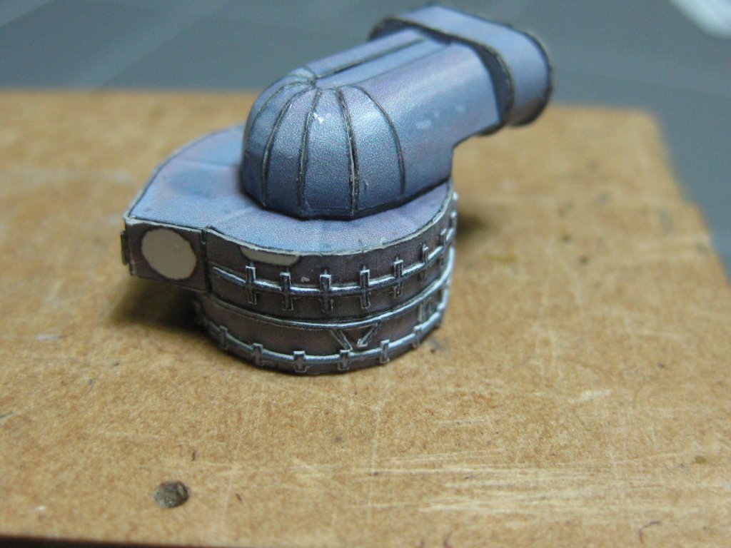
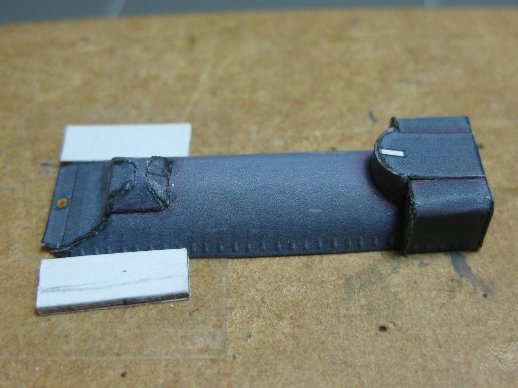
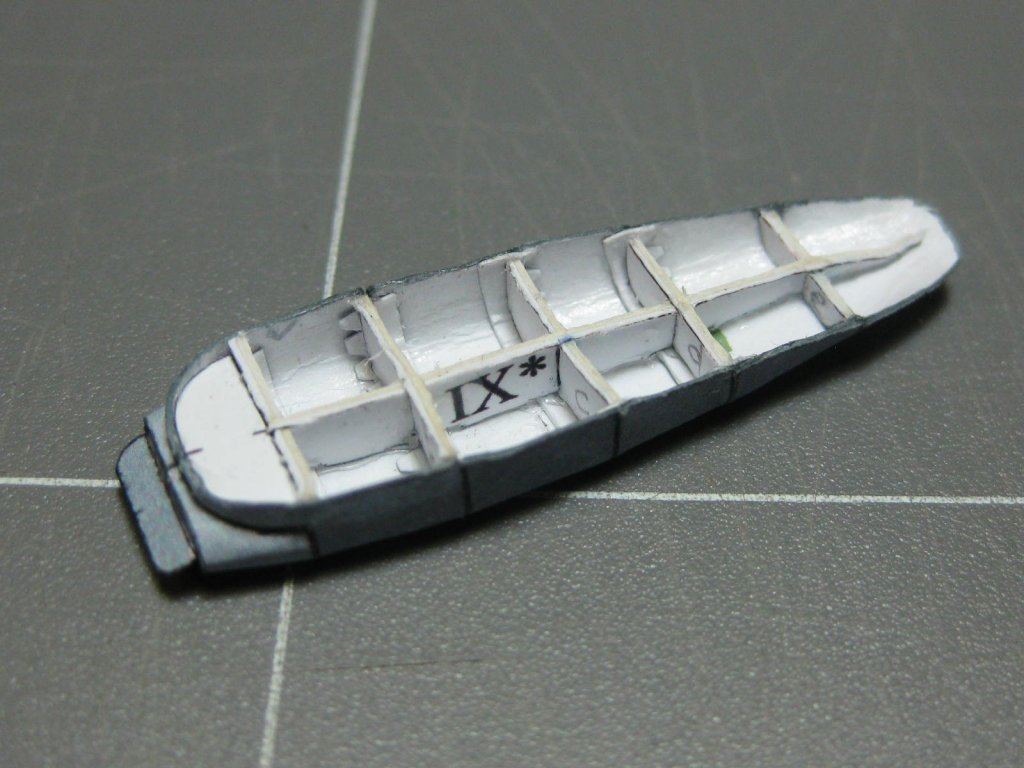
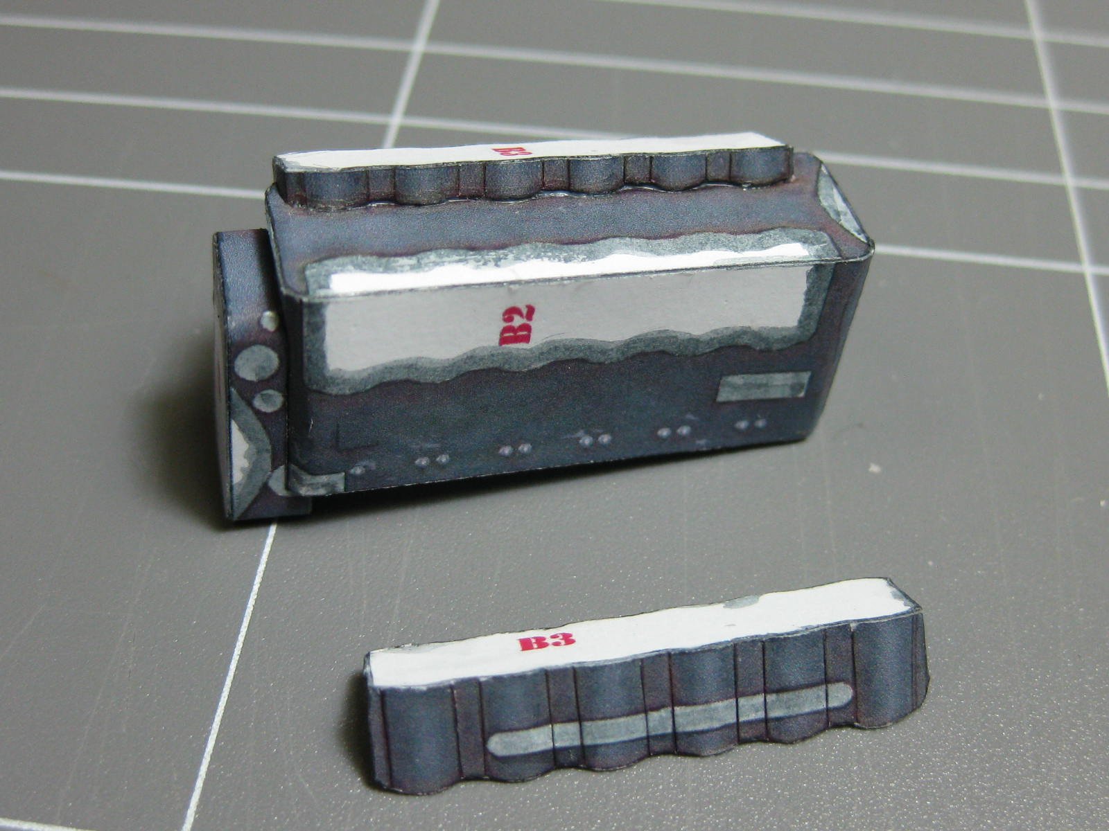
The supercharger finished :
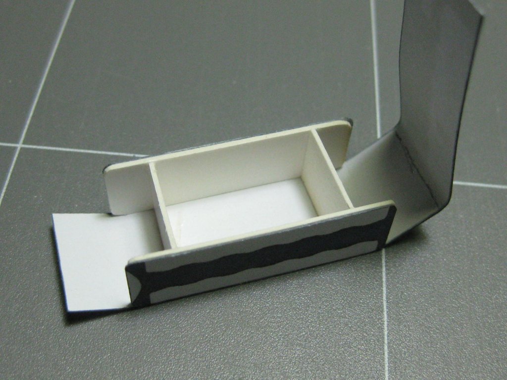
I reinforced the engine block with some 0.5mm card :
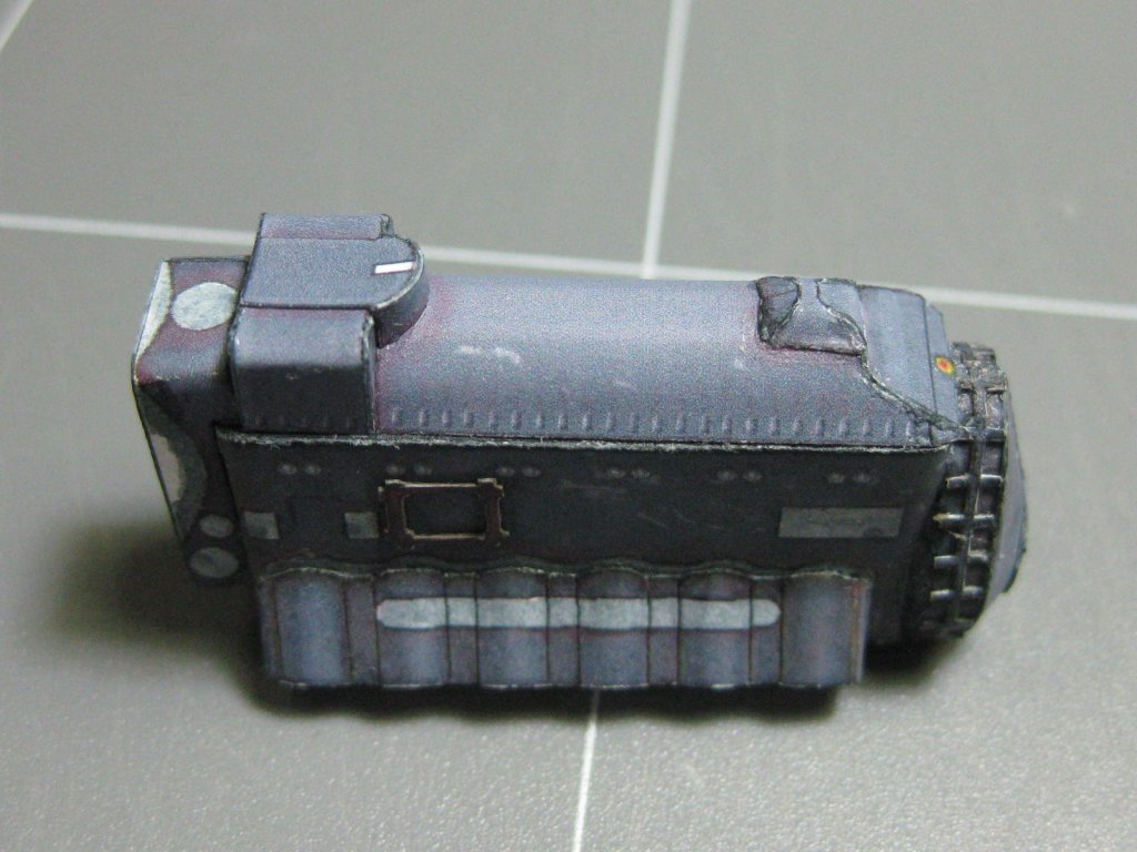
Another tricky piece :
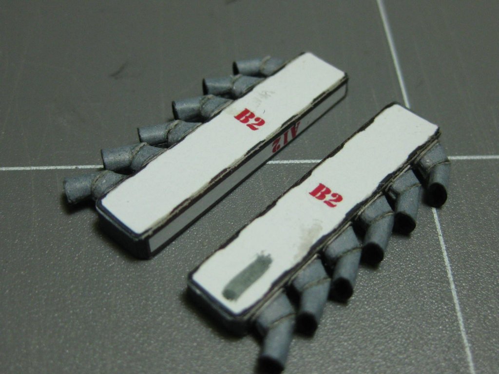
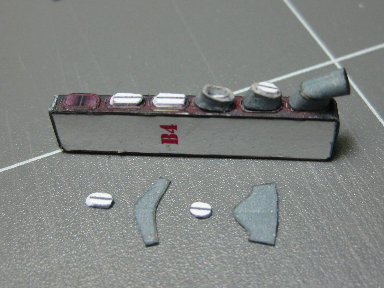
The cylinder heads took quite a bit of work due to the "bumps" on the sides :

The oil pan :
Danny
-
14 hours ago, CDW said:
Which model of home printer are you using Danny? Factory ink I presume?
Epson XP-520 with cheap aftermarket ink
.
8 hours ago, amateur said:That is small.....
what is the thickness of cardstock you use?
0.25mm Ultra Premium Matte Photo paper for the printed parts, the same for single laminations and up to 0.5mm and 1.0mm for thicker laminations depending on the part.
Danny
-
-
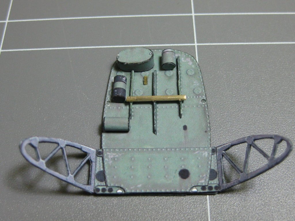
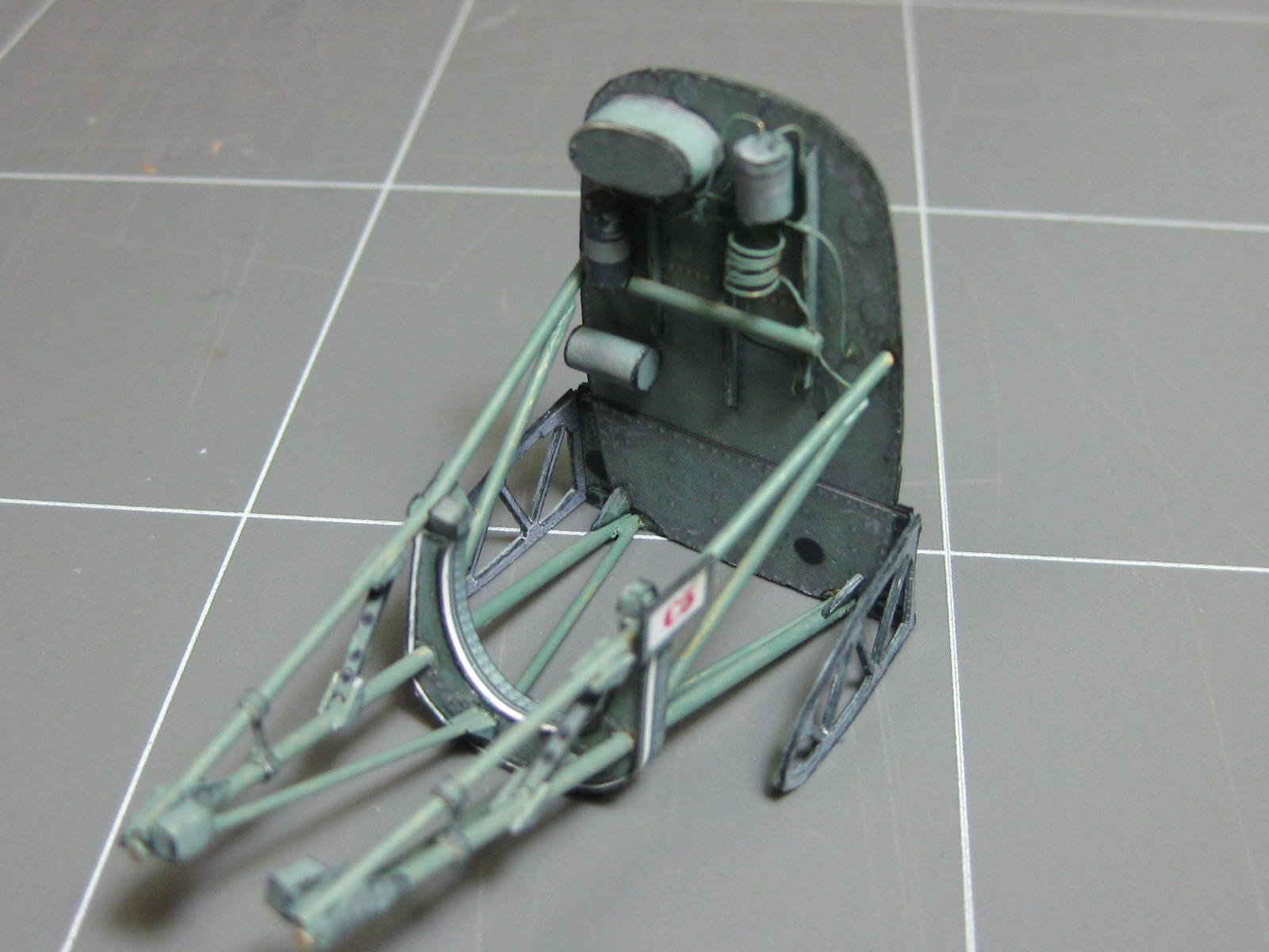
After gluing the framing to the bulkead I painted all the brass and touched up the edges using Acrylic mixed on a pallette :
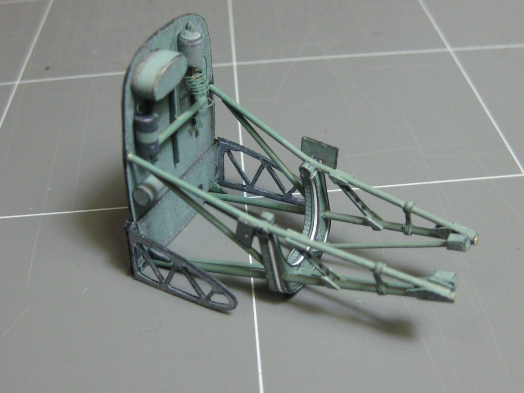
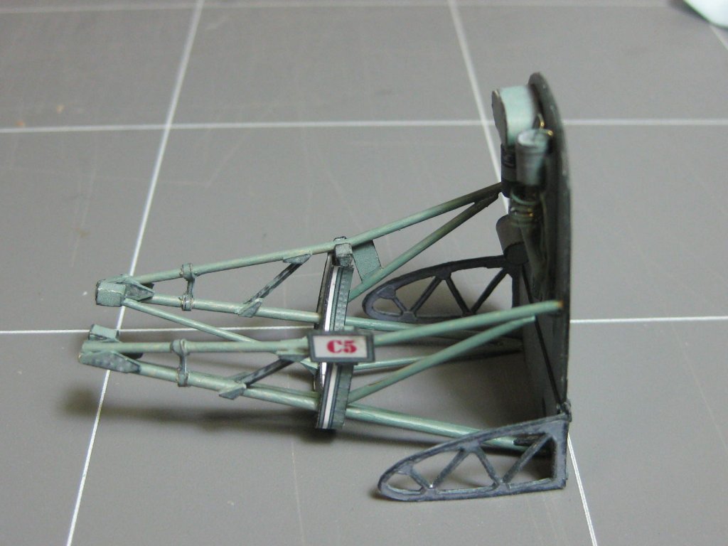
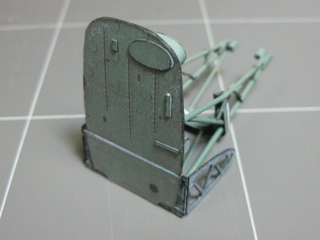
I almost forgot two lines. I'll touch them up next time I mix up this colour, as well as any small bits I missed. That will finish the framing part of the build. Here's a pic for size reference :
Next up I start the engine itself.
Danny
-
A welcome to all that are following this build
. I hope I can do it justice.
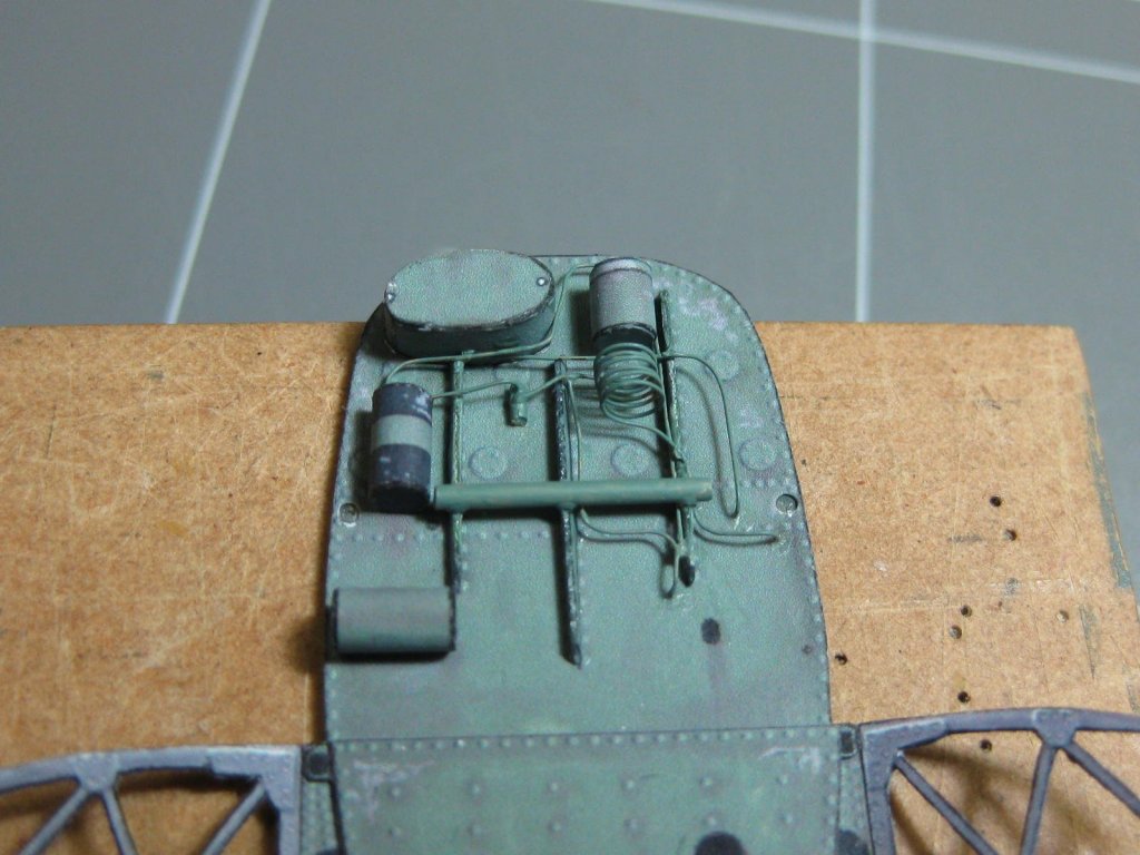
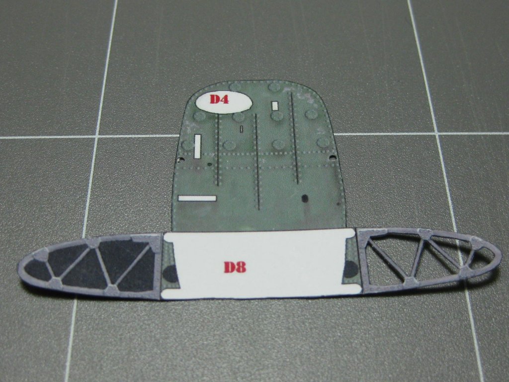
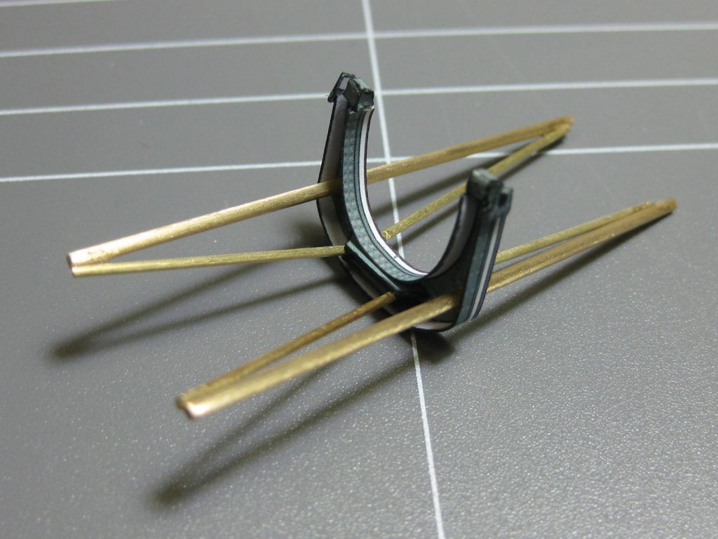
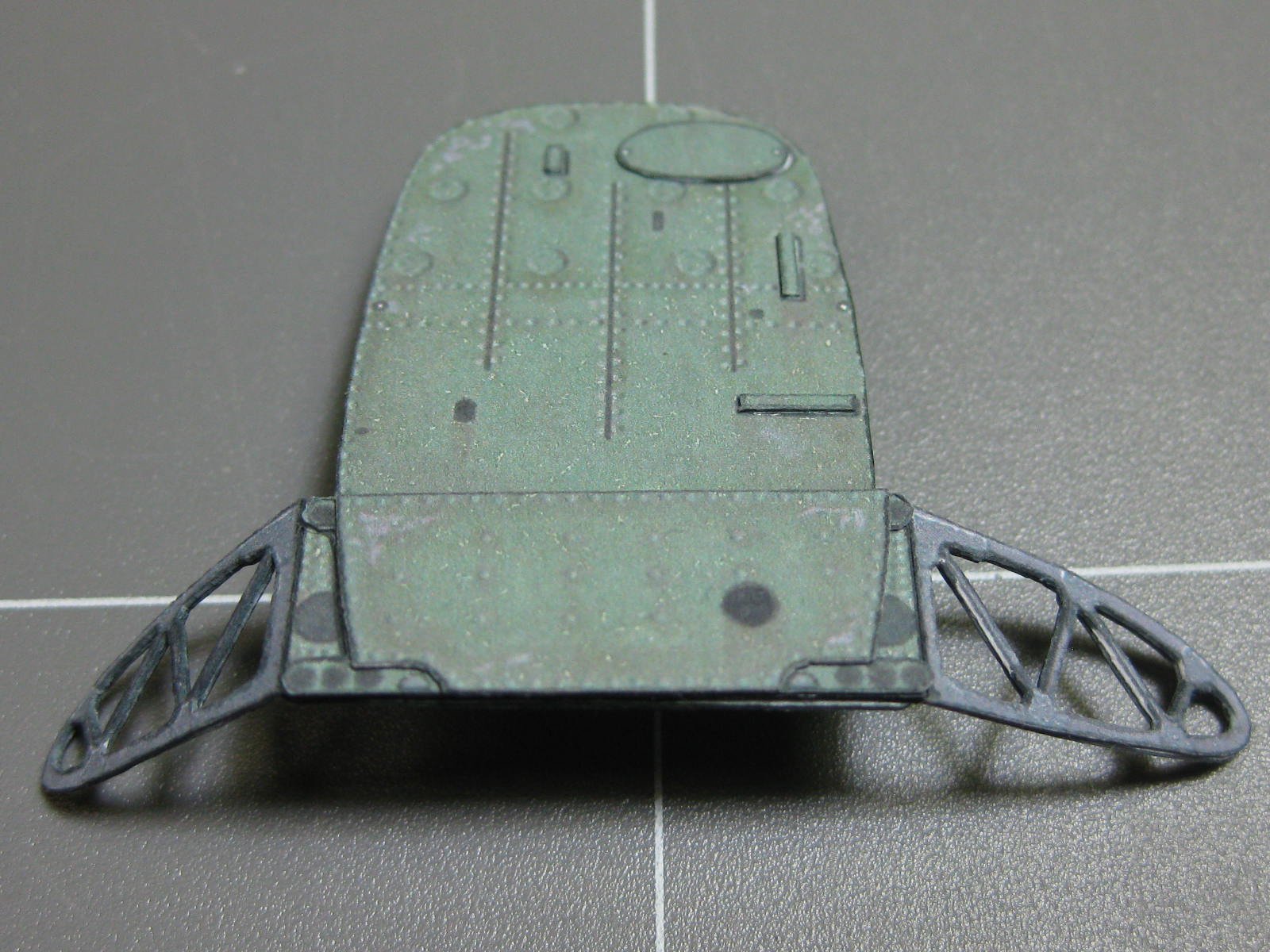
I reverse-printed a sheet of parts and laminated a backing piece to the firewall and side frame pieces. The firewall piece is not strictly accurate, but it's better than a simple white face. Cutting the holes out of the framing sections took a lot of care :
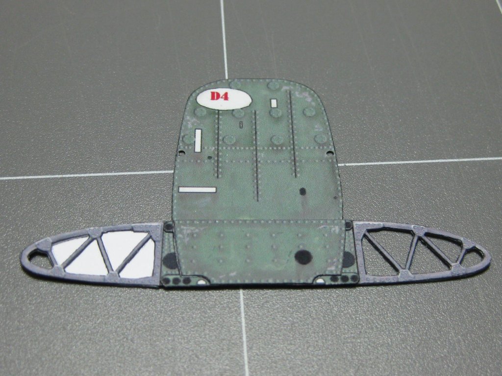
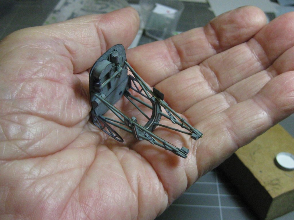
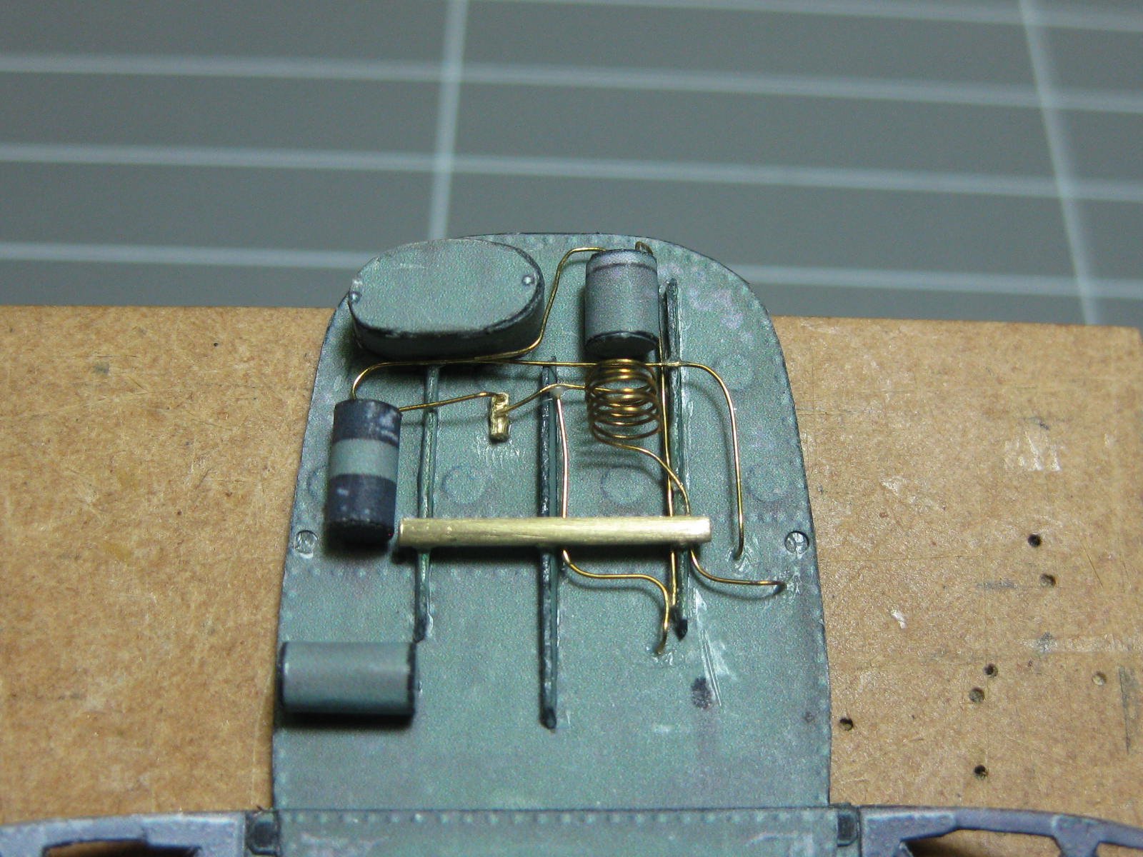
Next I detailed the firewall. The back side :

And the front. I used 0.2mm soft brass wire for the tubing :

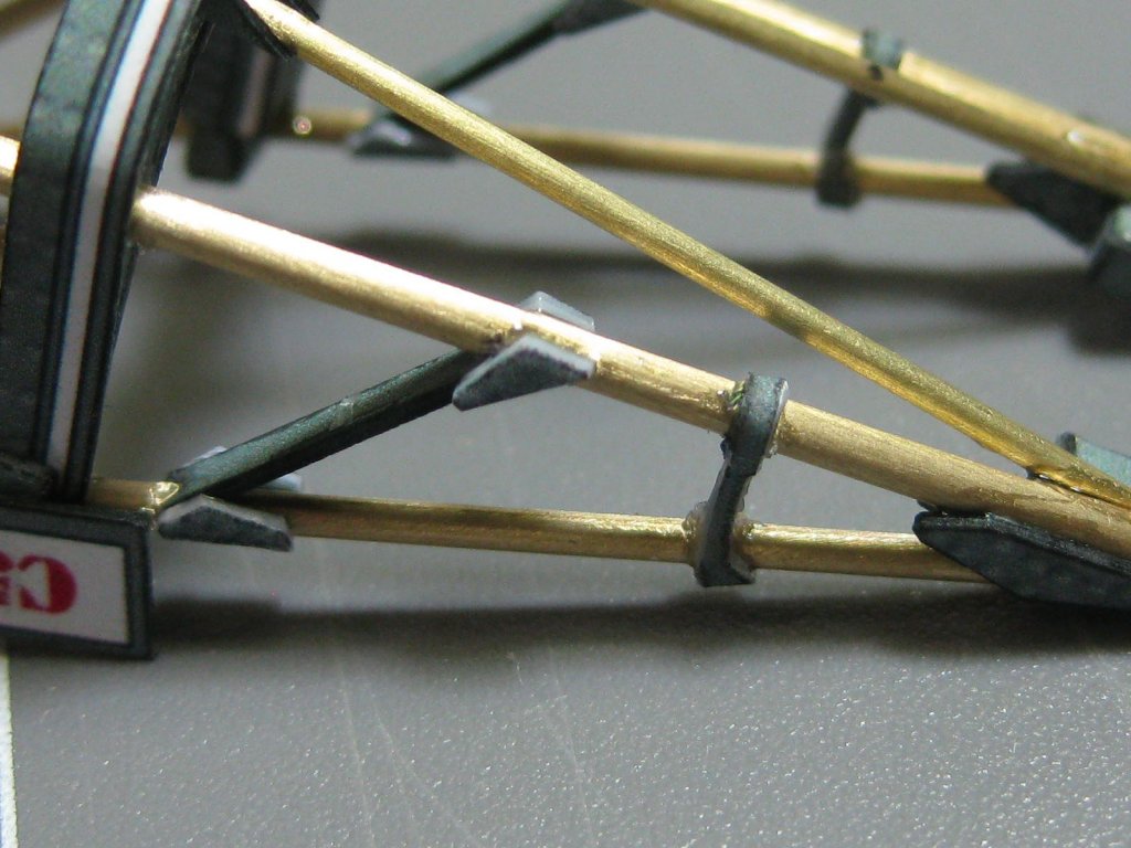
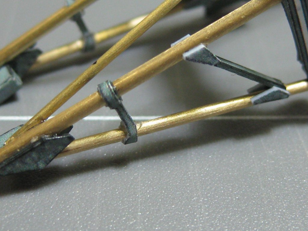
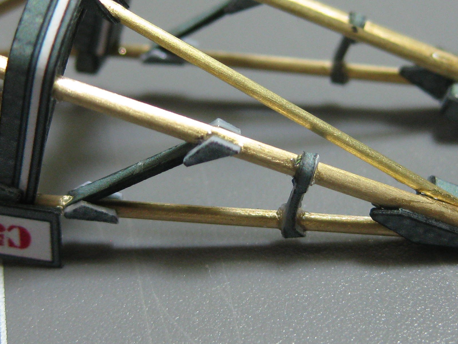
Some of the bracing for the framework was really tiny. These pieces are only 0.4mm wide at the narrow points :

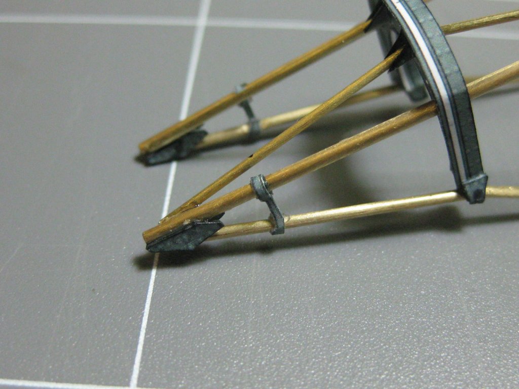
Gussets added :
Danny
-
15 hours ago, popeye the sailor said:
is the other spitfire the same scale as the engine? are you planning to install it?
Yes it is Popeye. If I build the 2nd Spitfire I'll build another engine as well and install it. However it might be a while coming, as I already have the next kit to follow after this build. More details on that one will be coming when I finish this one
.
Danny
- popeye the sailor, Canute, mtaylor and 2 others
-
5
-
7 hours ago, maaaslo said:
No Pav, it didn't
. Thanks for the link, but it's not actually the same one that I've downloaded even though it appears to be the same model engine and at 1/33 scale. That one looks like a scratchbuild, and a well done one at that. Just a pity that there weren't more pics.
And a welcome to all you guys as well
.
Danny
- Canute, mtaylor, popeye the sailor and 1 other
-
4
-
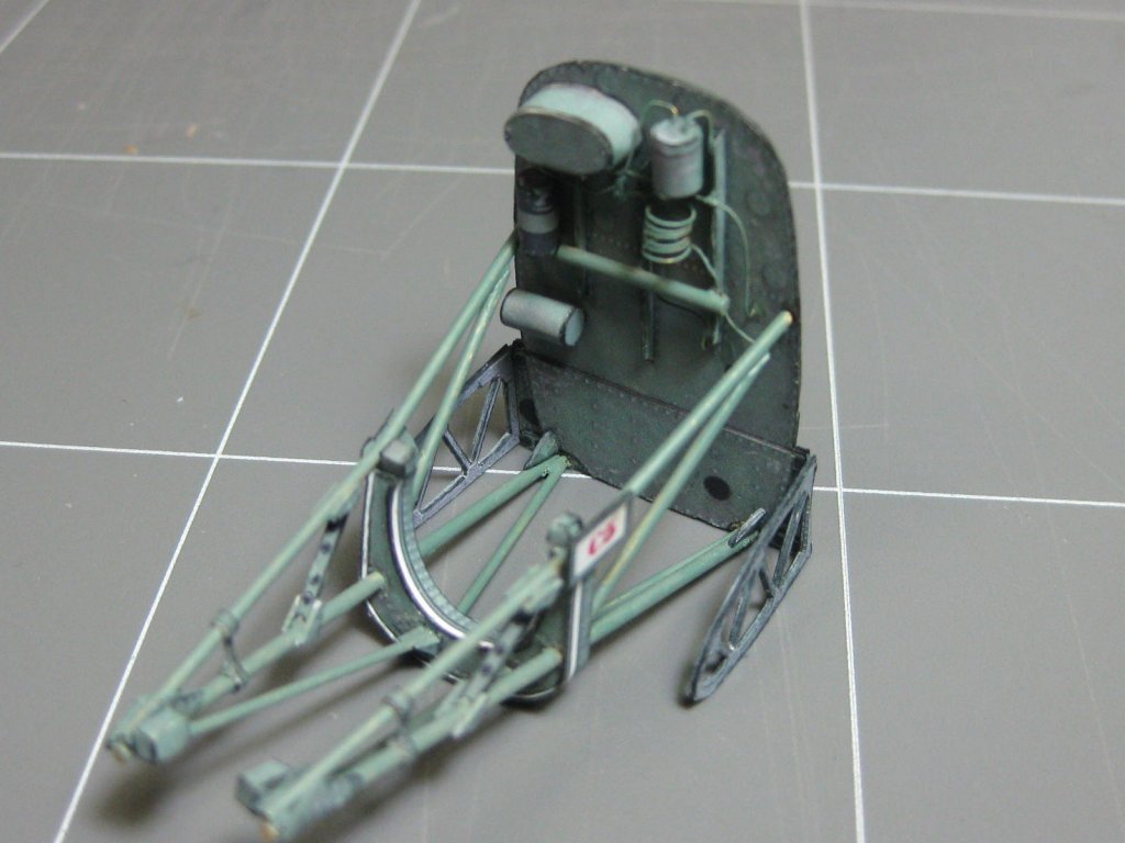
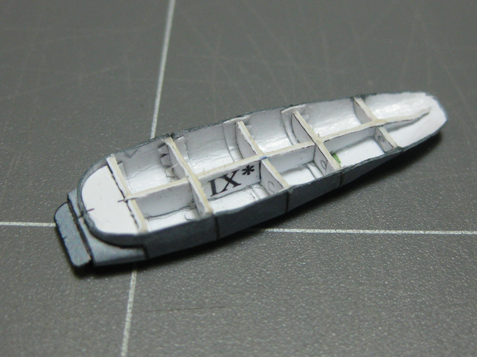
Hi all,
Here's a tricky build. It's a 1/33 scale attempt at a Rolls Royce Merlin engine to be displayed as a "stand-alone" model next to the Mk. IX Spitfire I built. It's a design by Alin Osarik and a downloadable copy of it can only be found on THIS SITE.
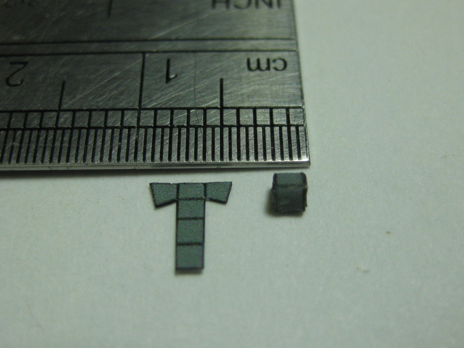
As far as I'm aware no-one has successfully managed to build one at this small a scale, and no wonder - some of the parts are TINY
. All other builds I have seen have been blown up to 1/16 scale. But I'll have a go .
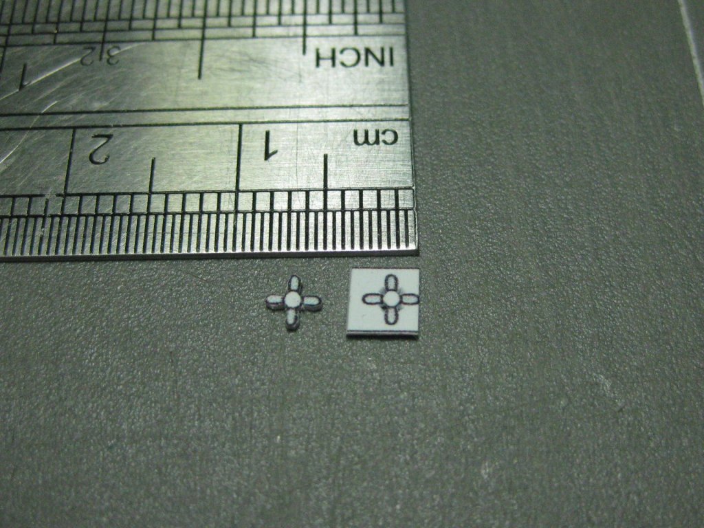
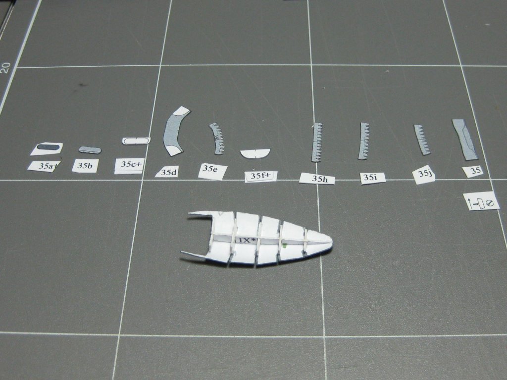
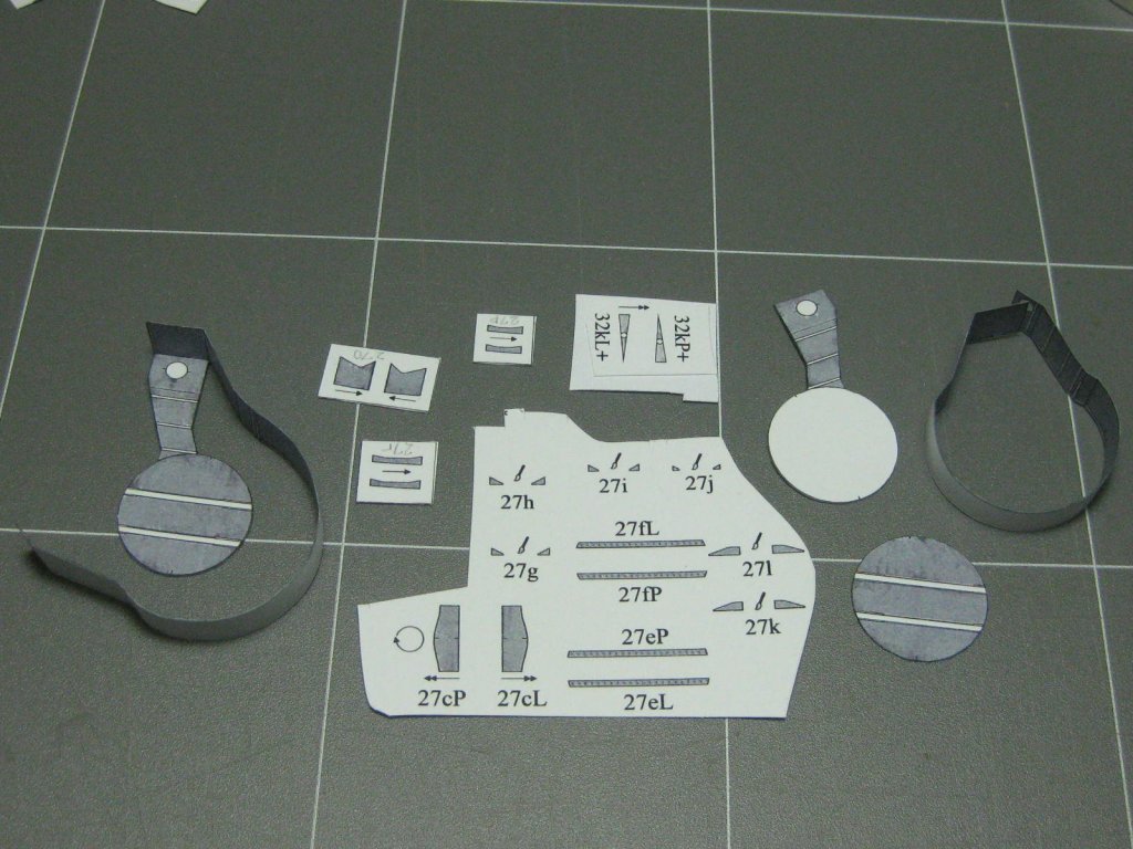
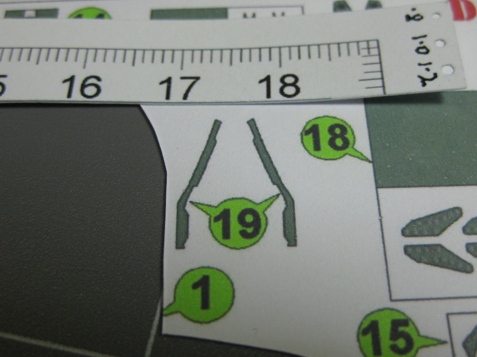
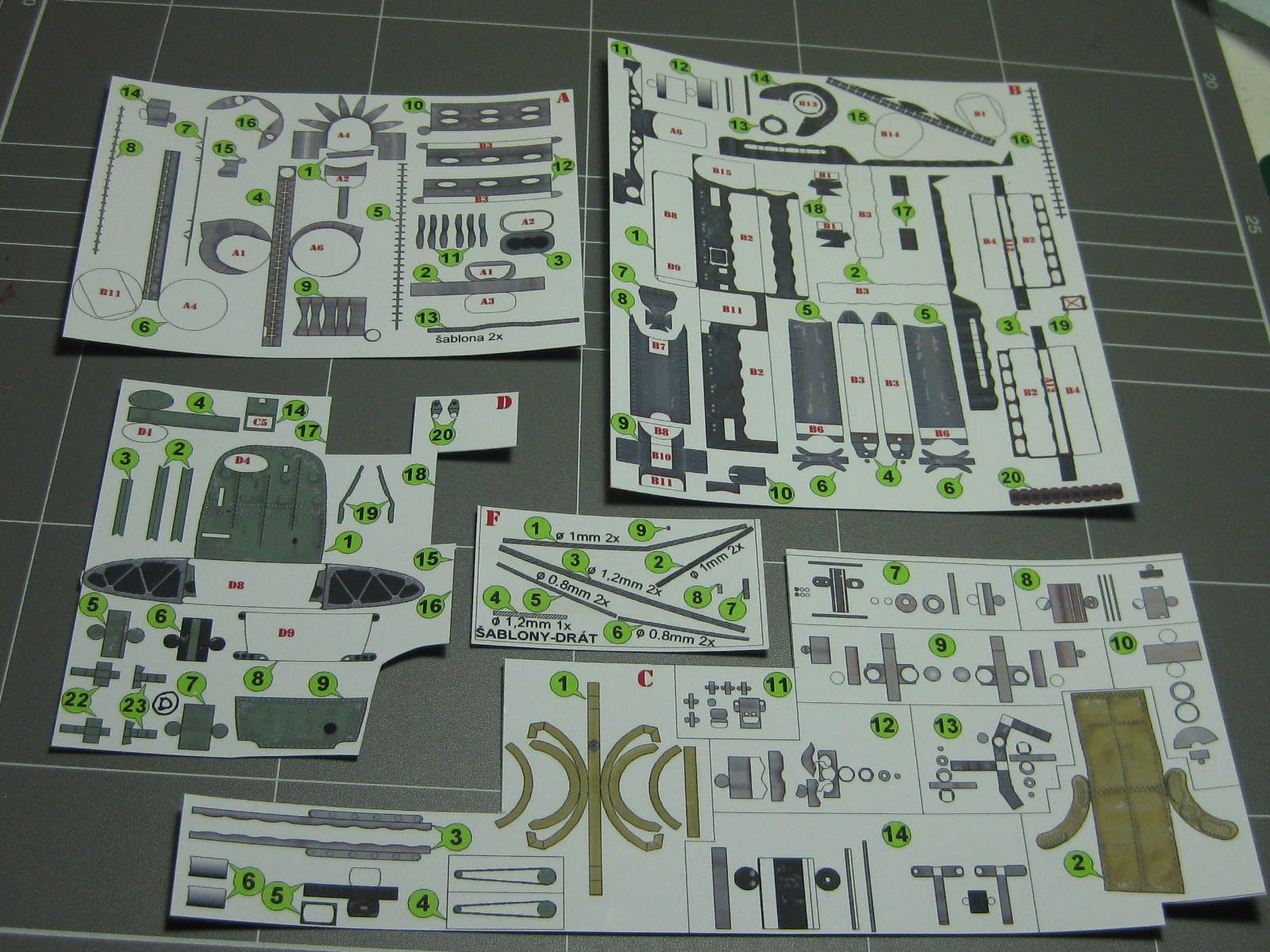
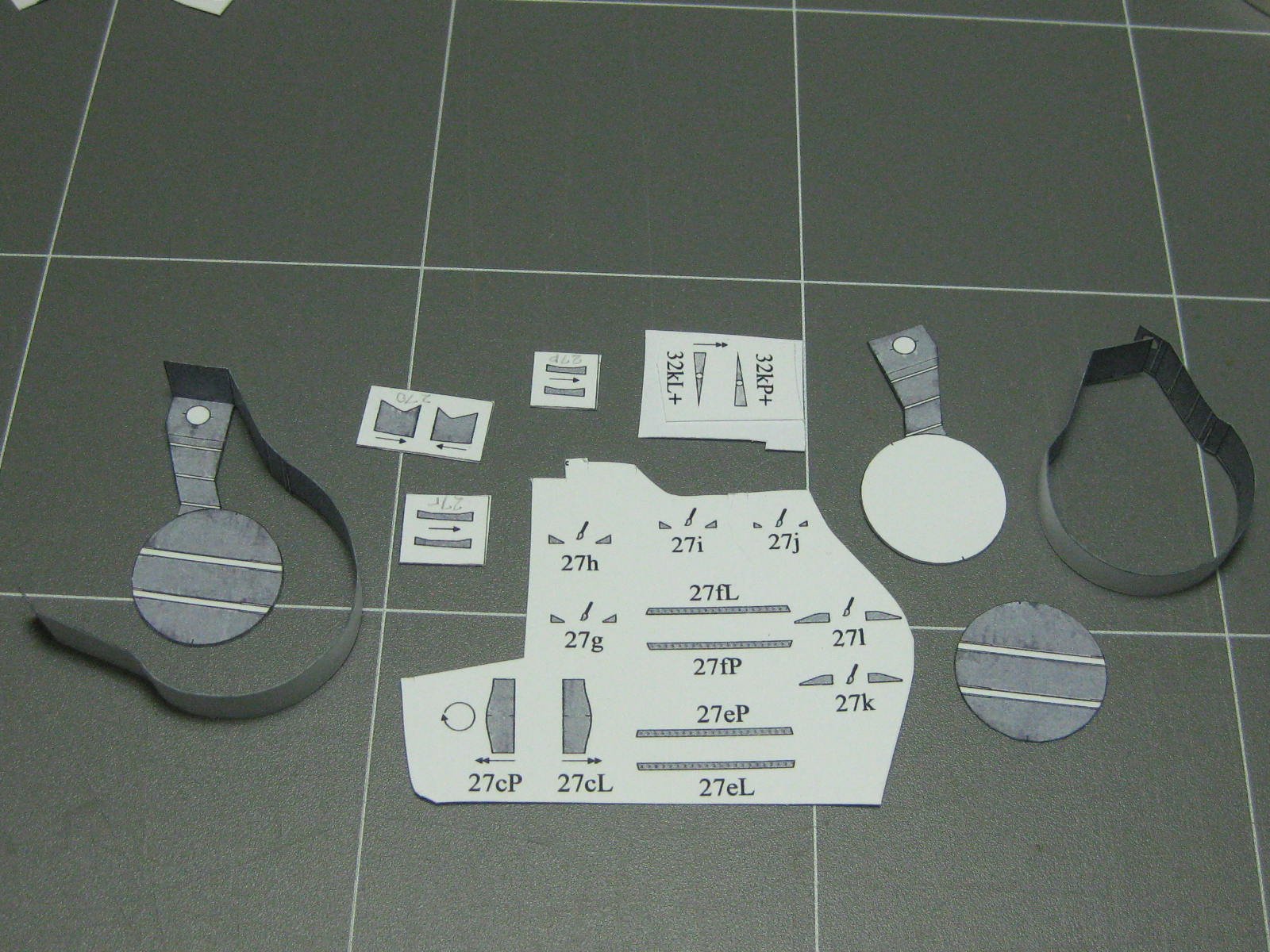
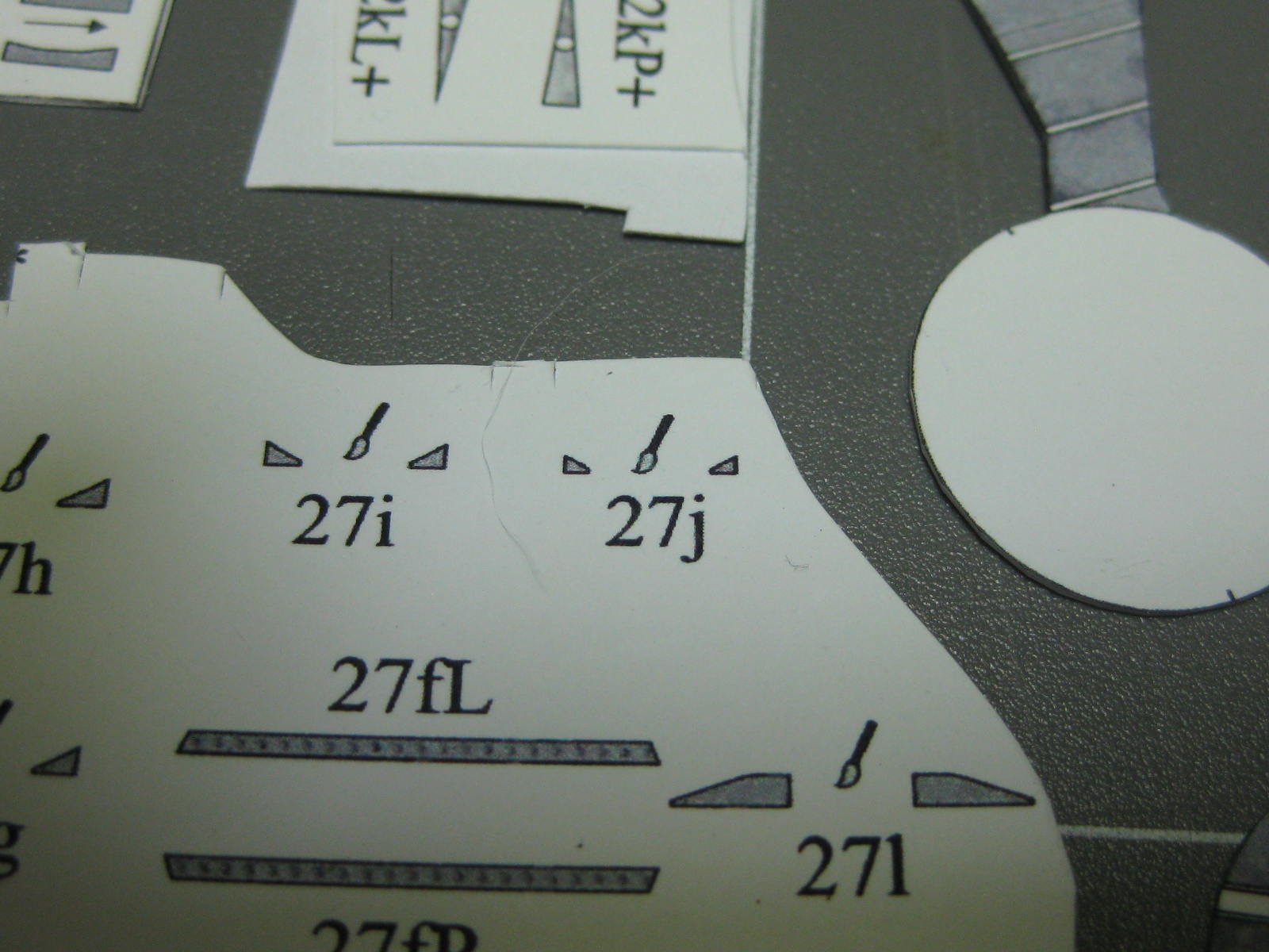
Here's a pic of the parts. They come on one page, but there are a further 34 pages of step-by-step rendered photo instructions :
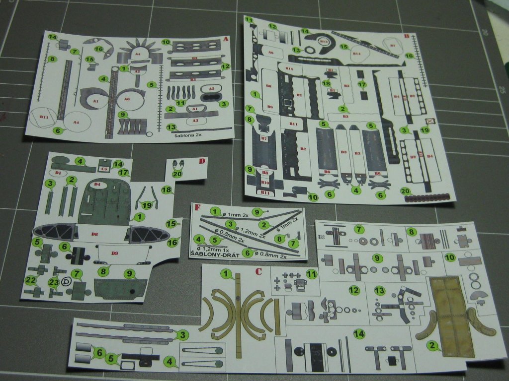
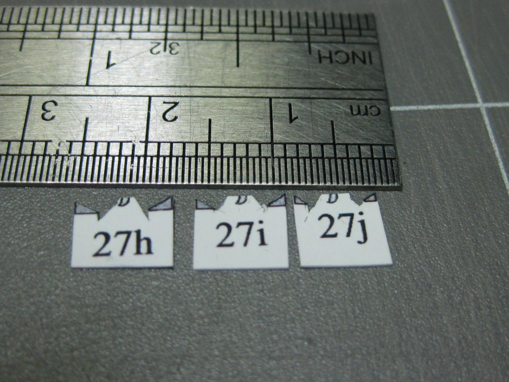
One example of the size of the parts :

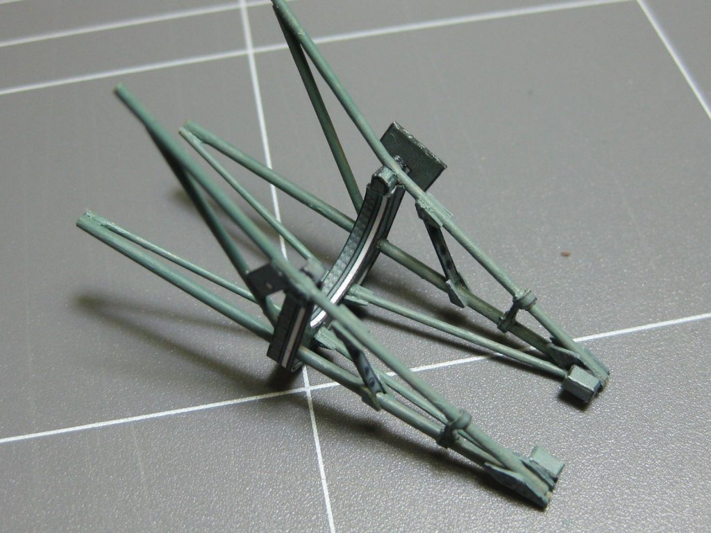
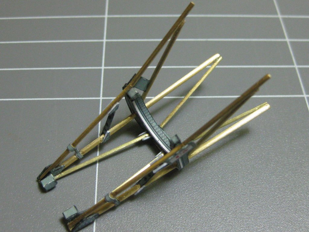
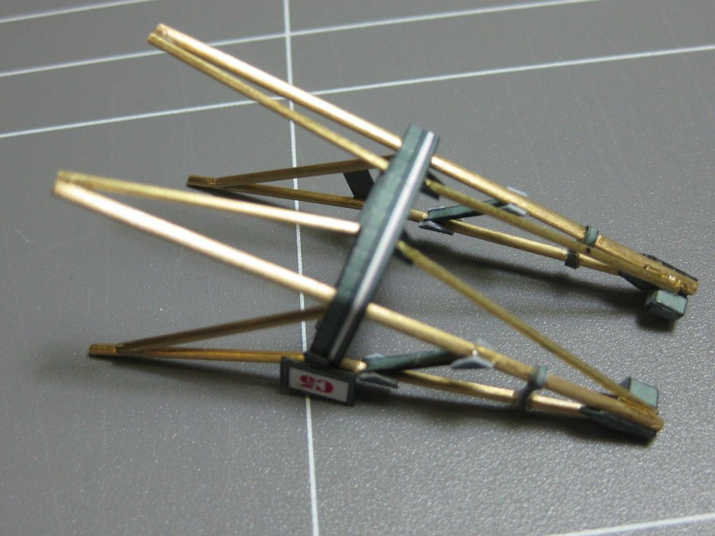
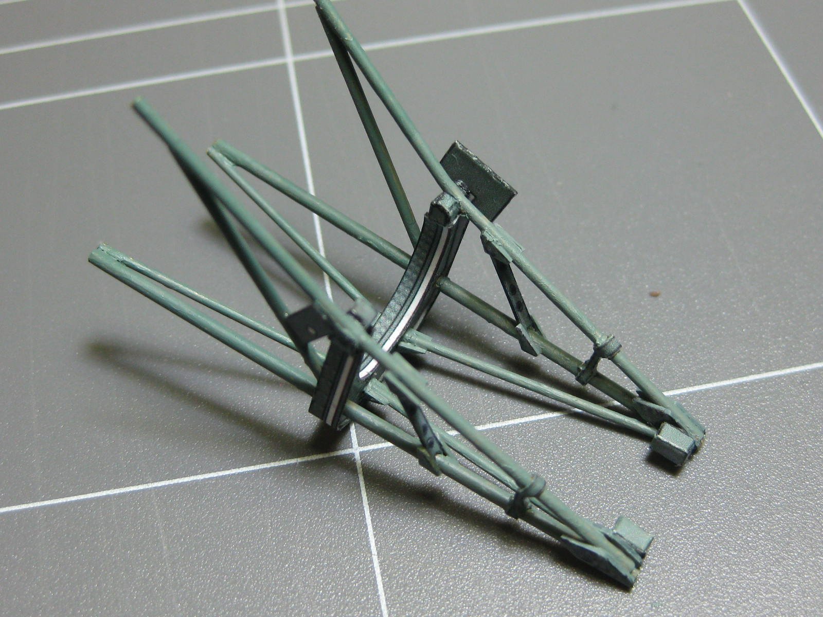
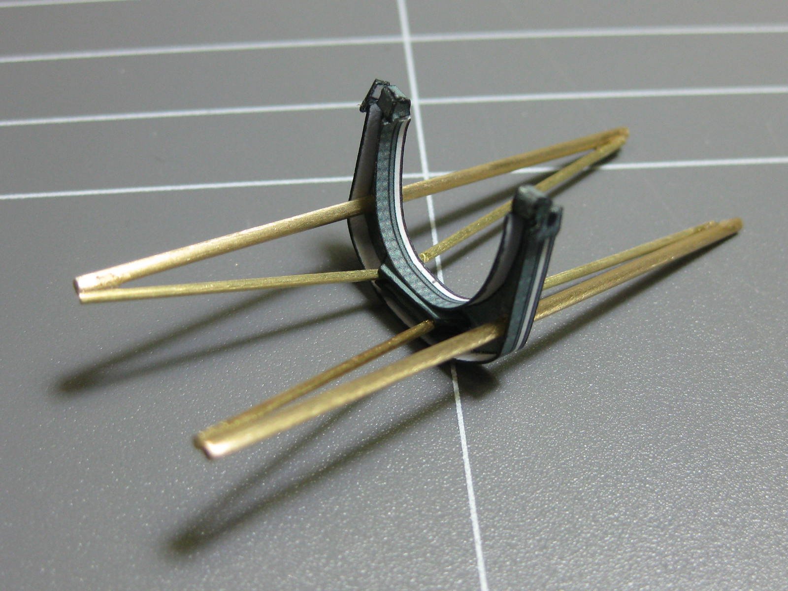
And this is what I've done so far. This is the start of the engine compartment framework that supports the engine. It's been designed to fit inside the Halinski Card Spitfire, which may be a future build for me as I have a 2nd model Spitfire that came with the original kit that I've already built.
Danny
- GrandpaPhil, Sea Hoss, Dubz and 13 others
-
16
-
11 hours ago, maaaslo said:
Nice work Danny. One comment maybe. On the first page of the thread, a lot of pics dont show. Would you be able to reupload them so i too can admire?
They are all OK on my computer Pav. Perhaps you have a problem with your computer's Operating System. Sometimes if your Internet connection is running a bit slow it can take some time to load the pics and they only come up as the link to them at first.
Does anyone else have a problem seeing all the pics?
Danny
-
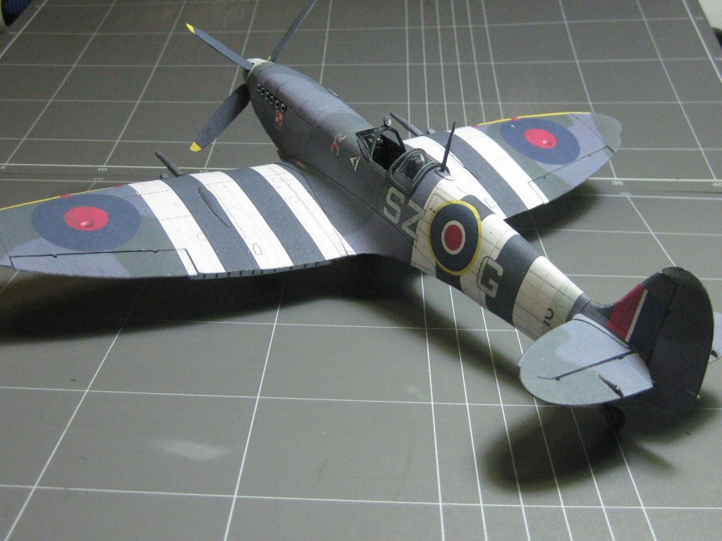
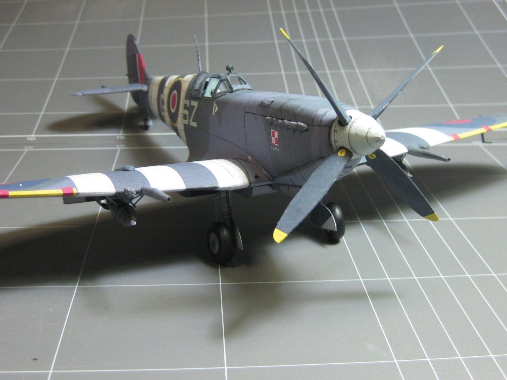
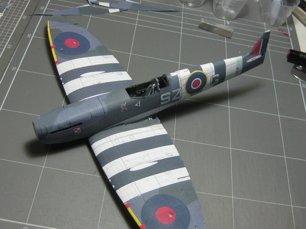
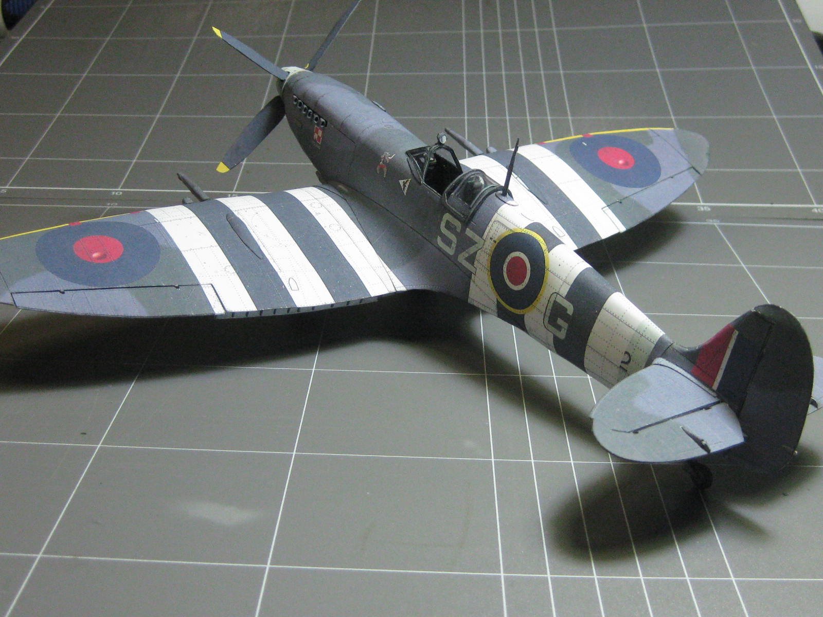
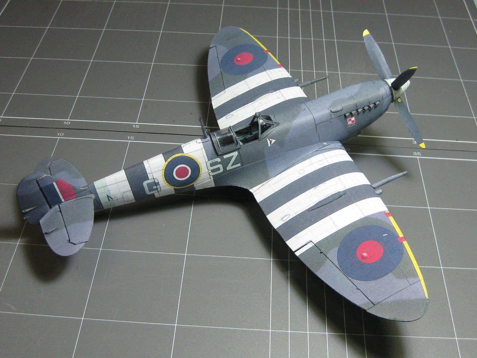
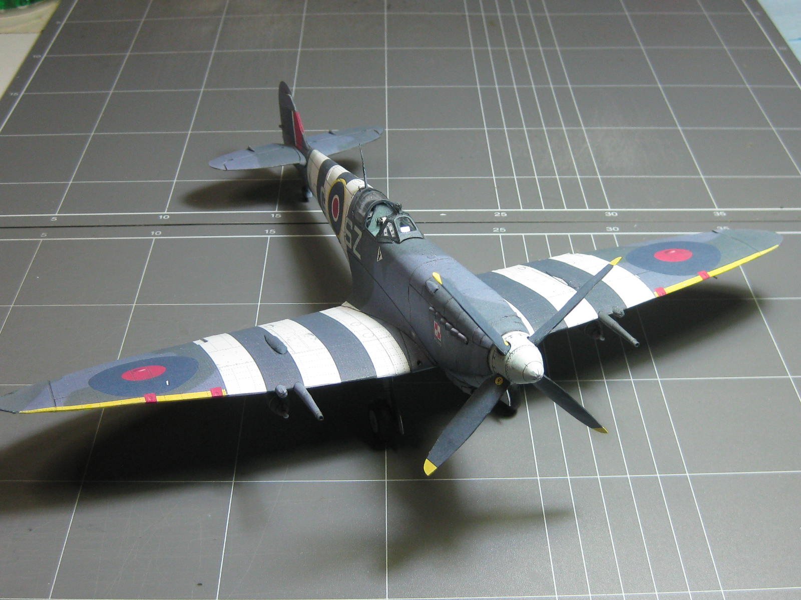
After fitting the small details the model is FINISHED
. It was a very enjoyable kit to build, and I'm going to make the Merlin engine next as a "stand-alone" build to be displayed alongside the plane :


Danny
- GrandpaPhil, cog, druxey and 18 others
-
21
-
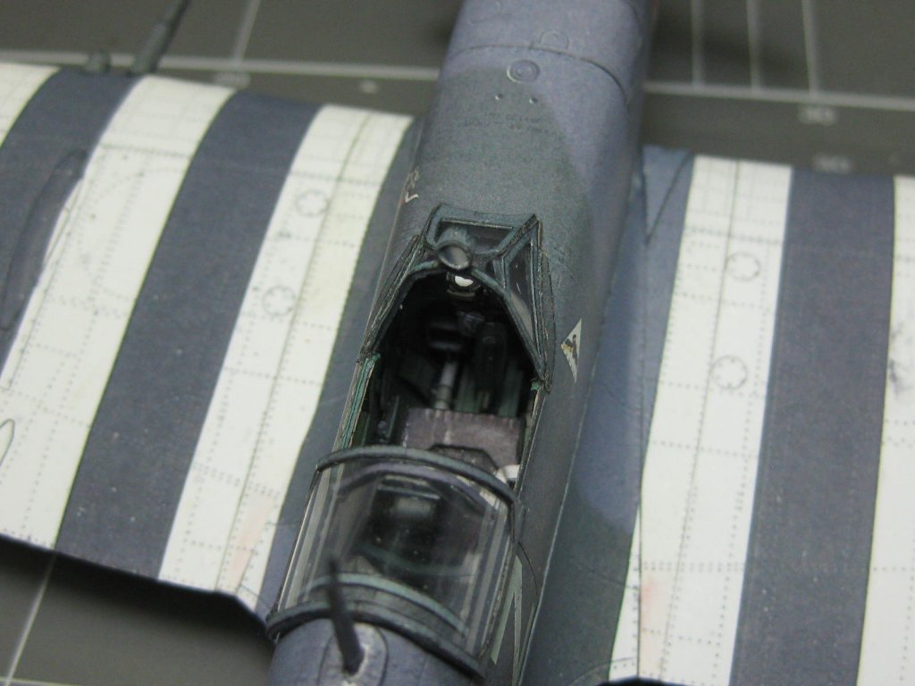
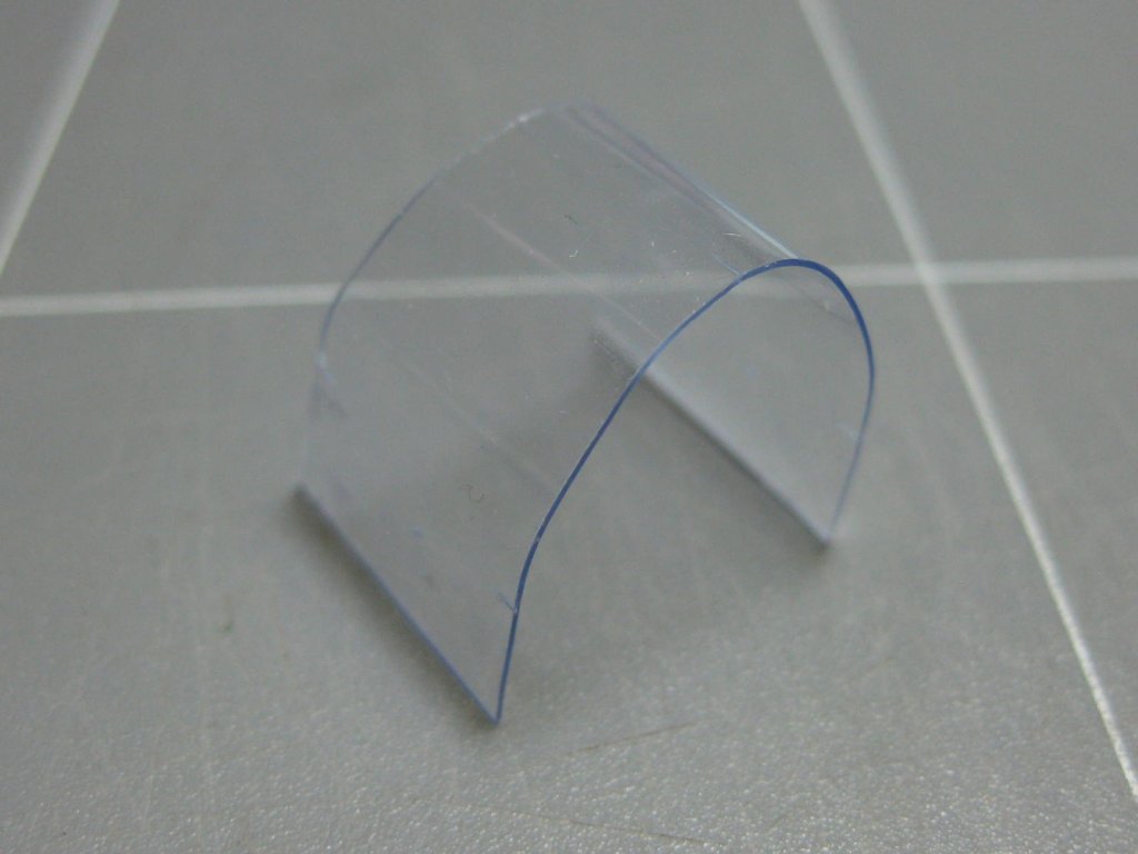
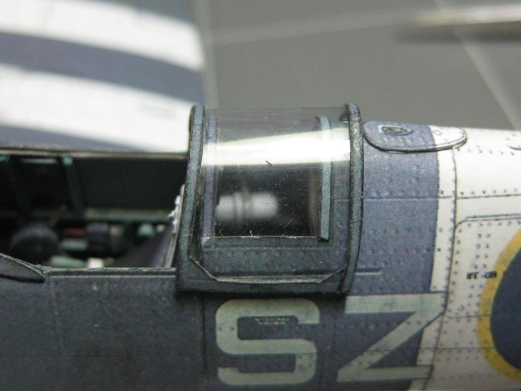
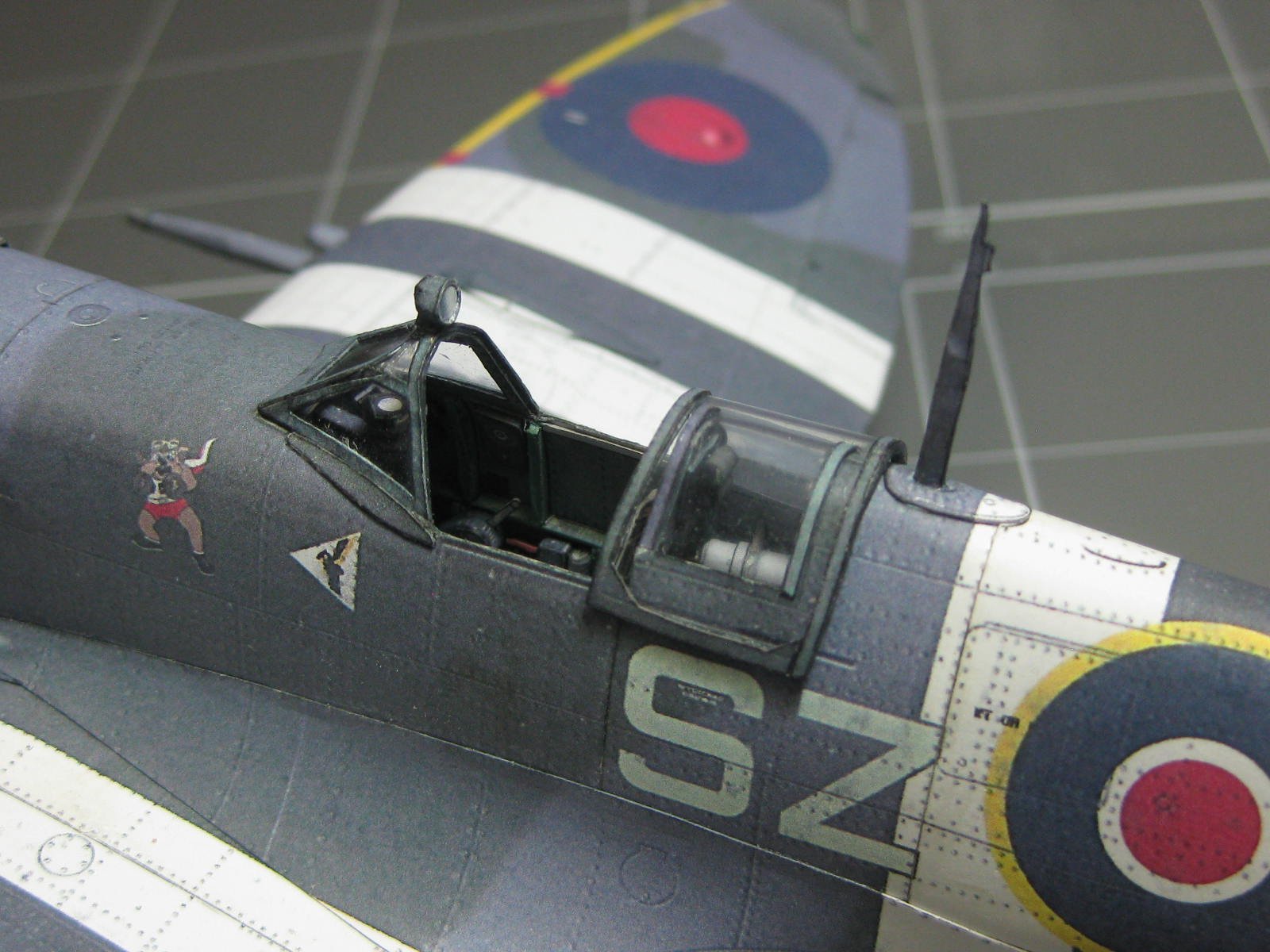
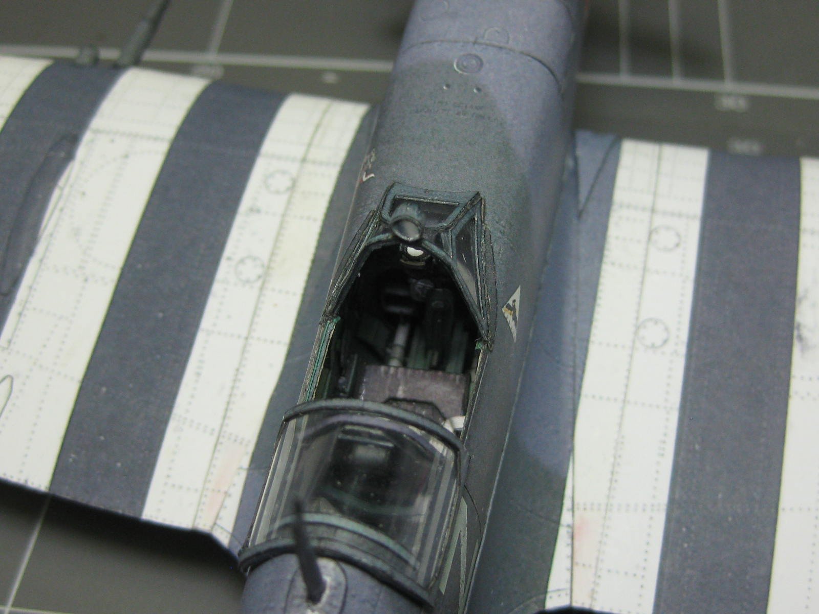
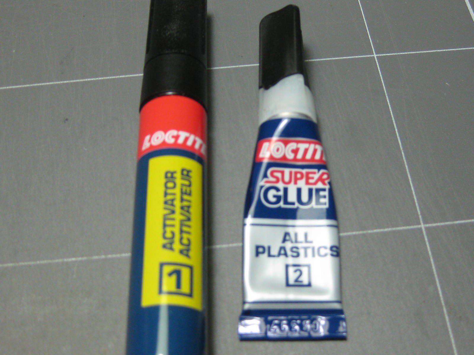
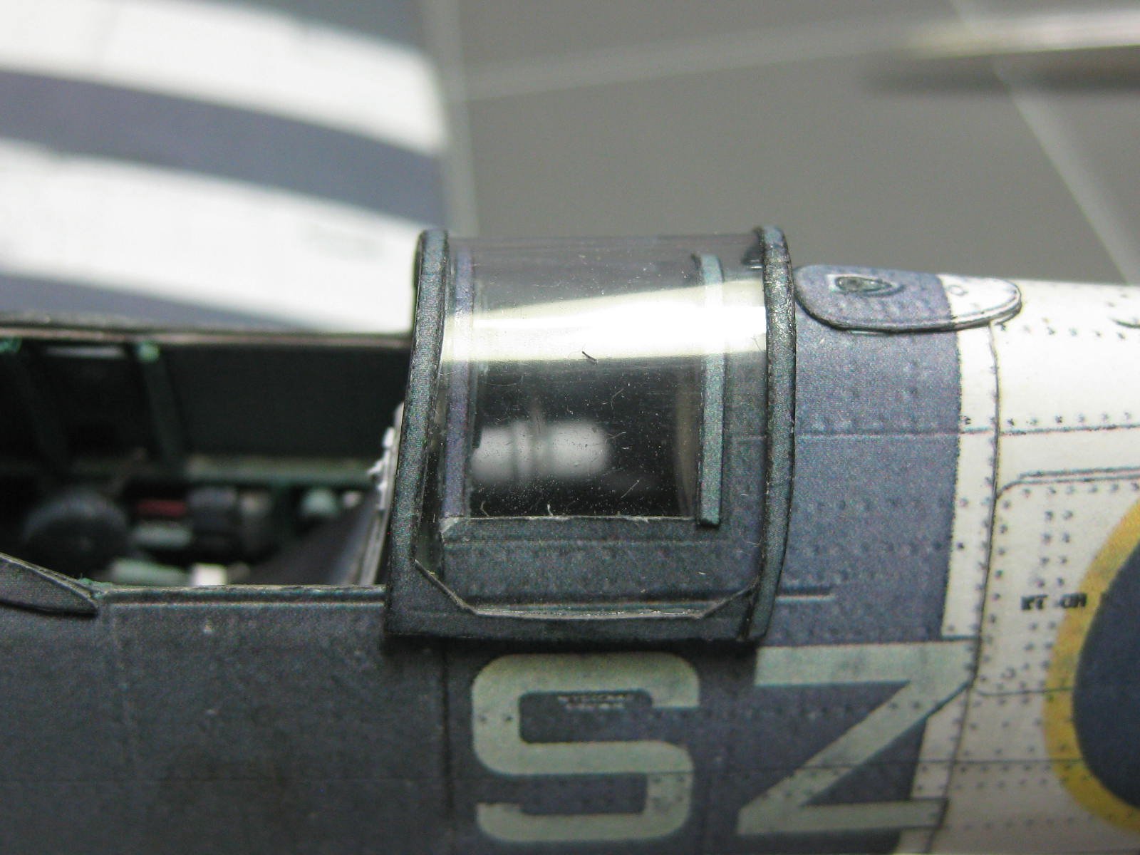
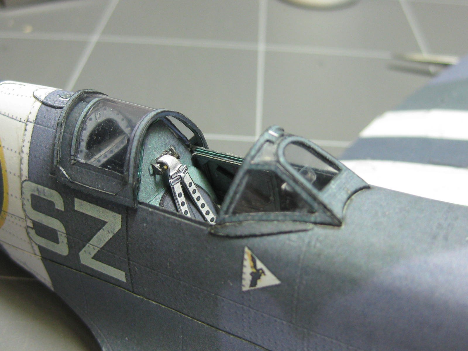
I also didn't know about the pre-molded canopy when I ordered the kit, so everything is made from 0.25mm acetate. Gluing this stuff is almost impossible without the right glue. Fortunately Loctite make one that actually works
. It comes with an activator which must be applied before the super-glue :

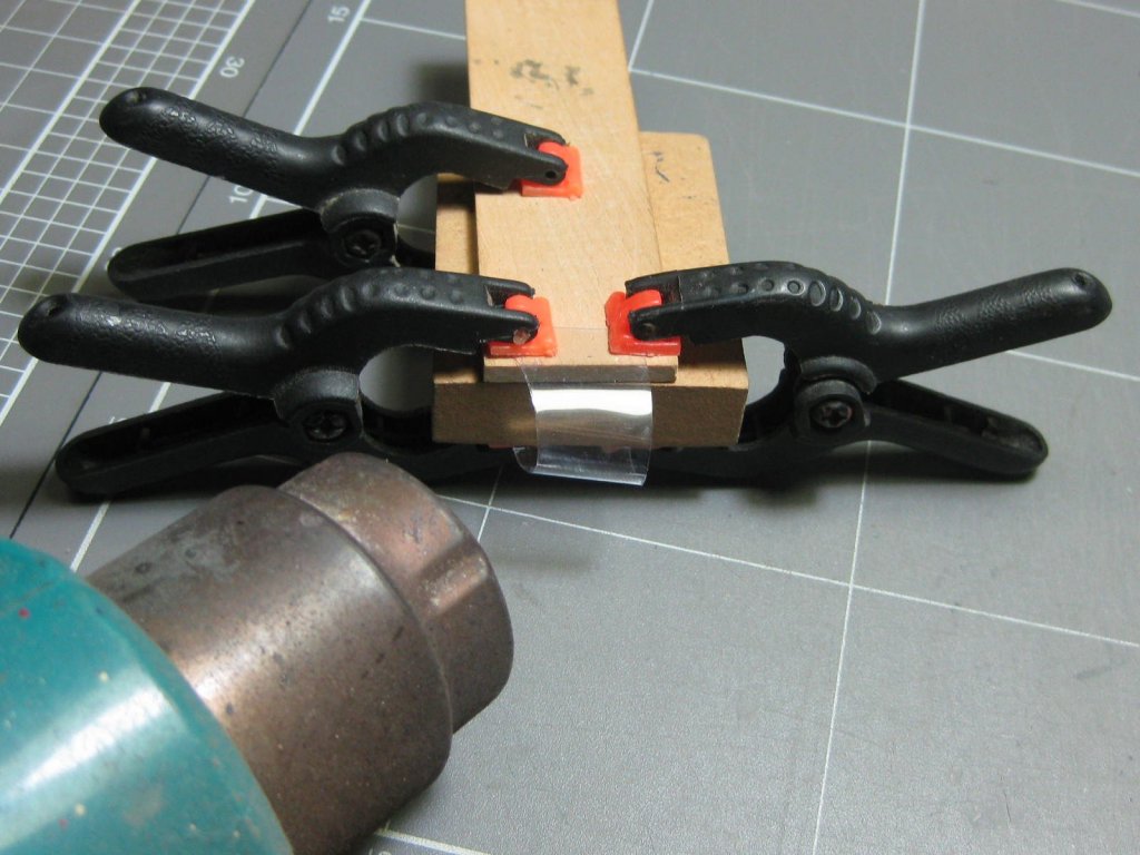
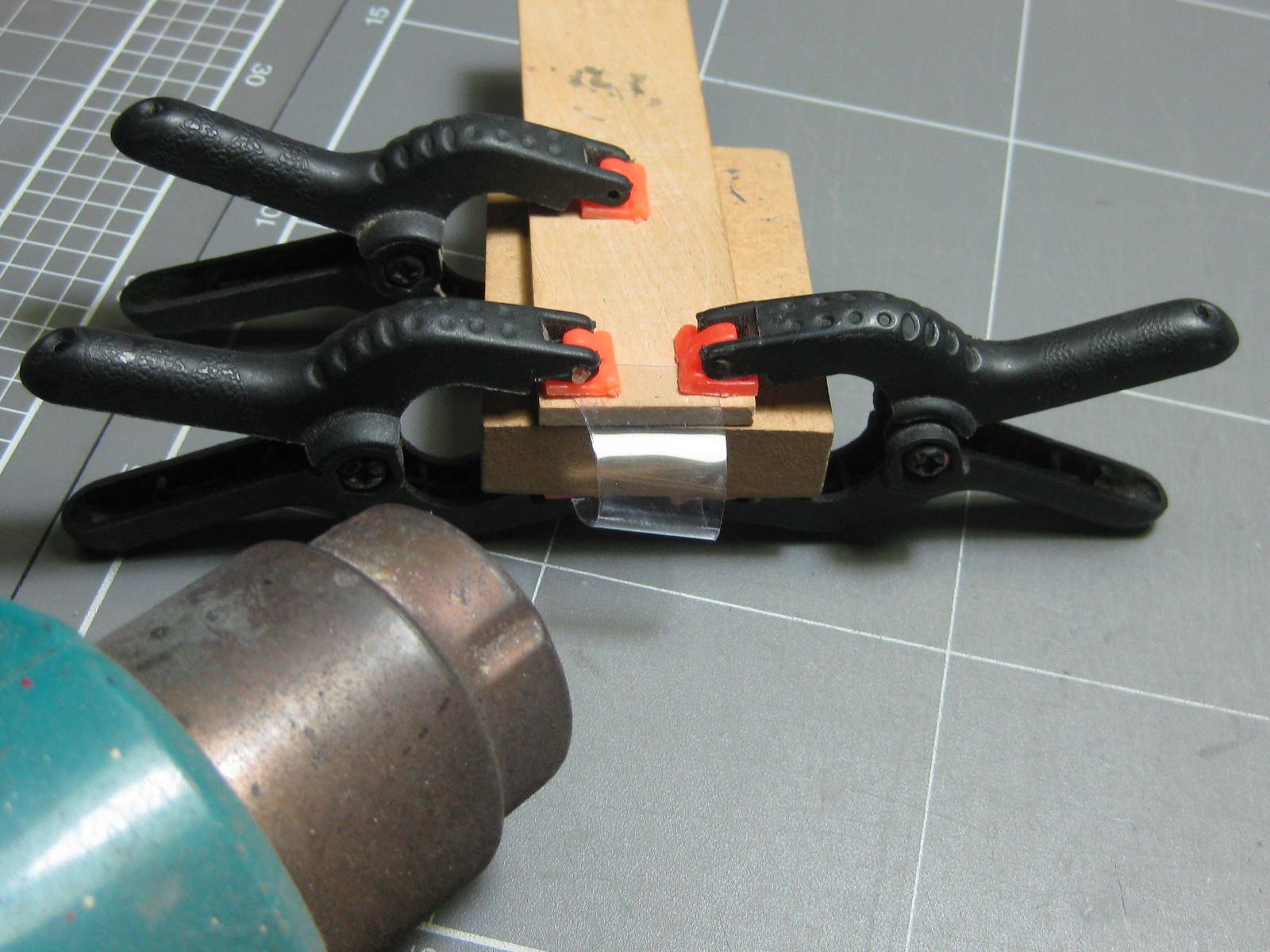
To shape the curved parts I clamped them to some scrap timber and used my heat gun on low setting to CAREFULLY bend them permanently. A couple of goes were needed before I found the right amount of heat without melting the pieces :
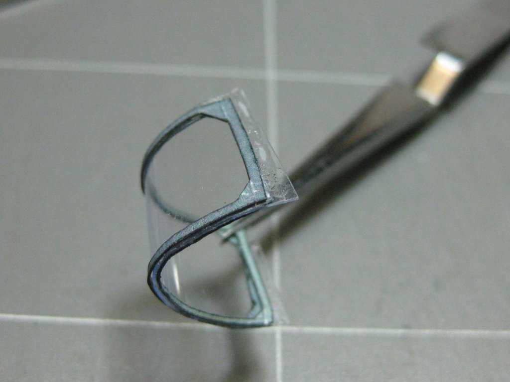
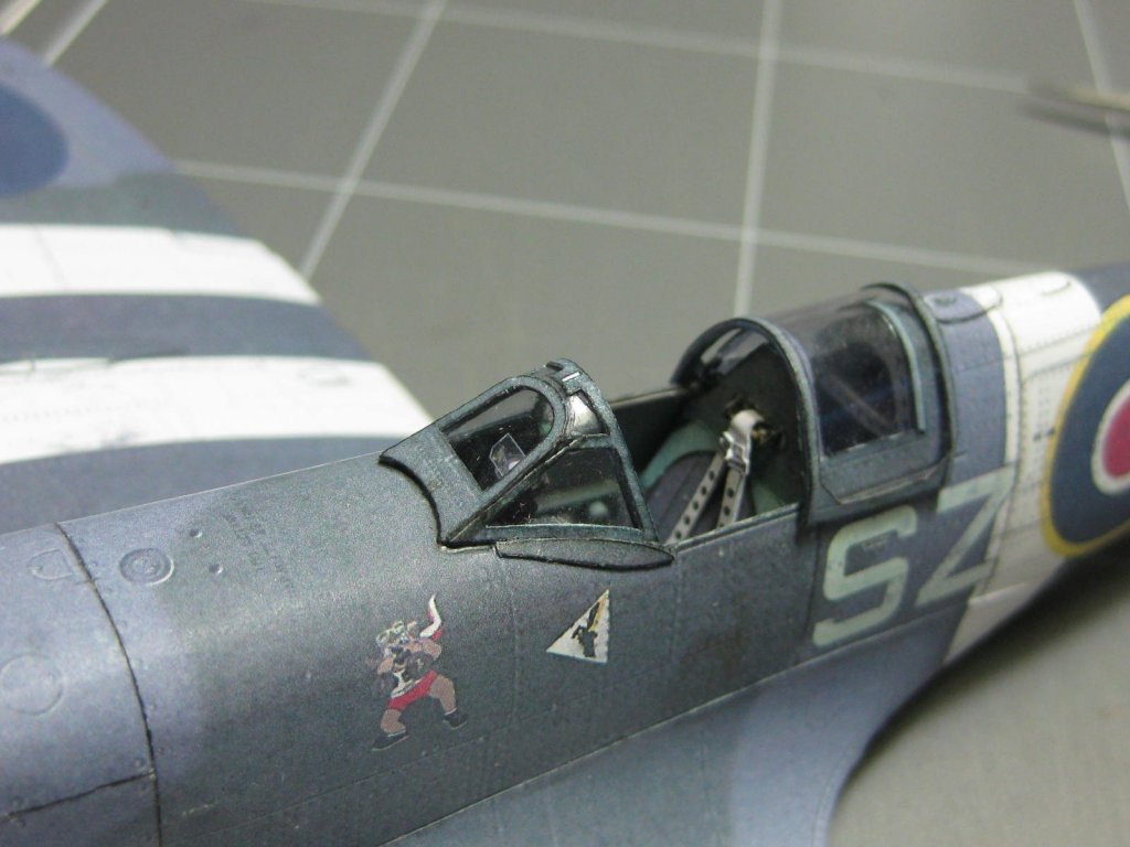
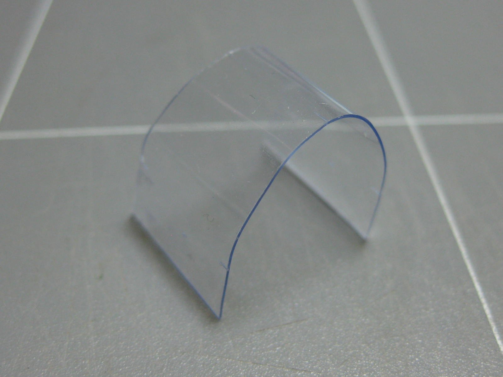
The canopy frames have an inside and an outside. The Loctite glue worked well, but a lot of care was needed to align the pieces properly. The excess was trimmed off after the glue dried :
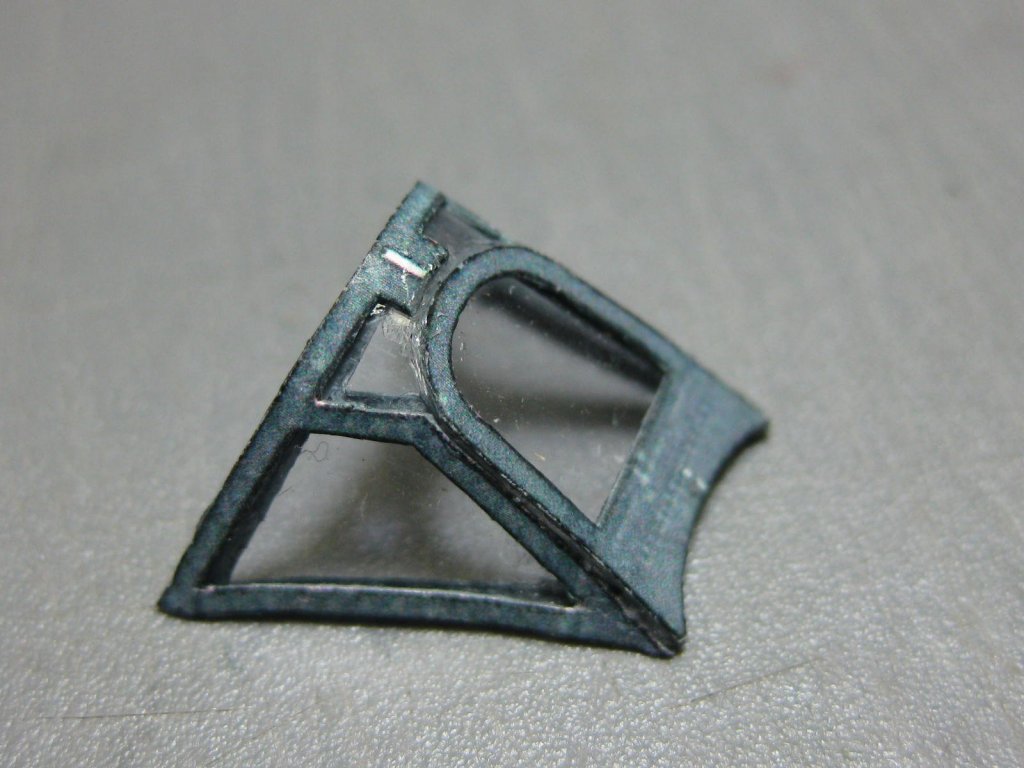
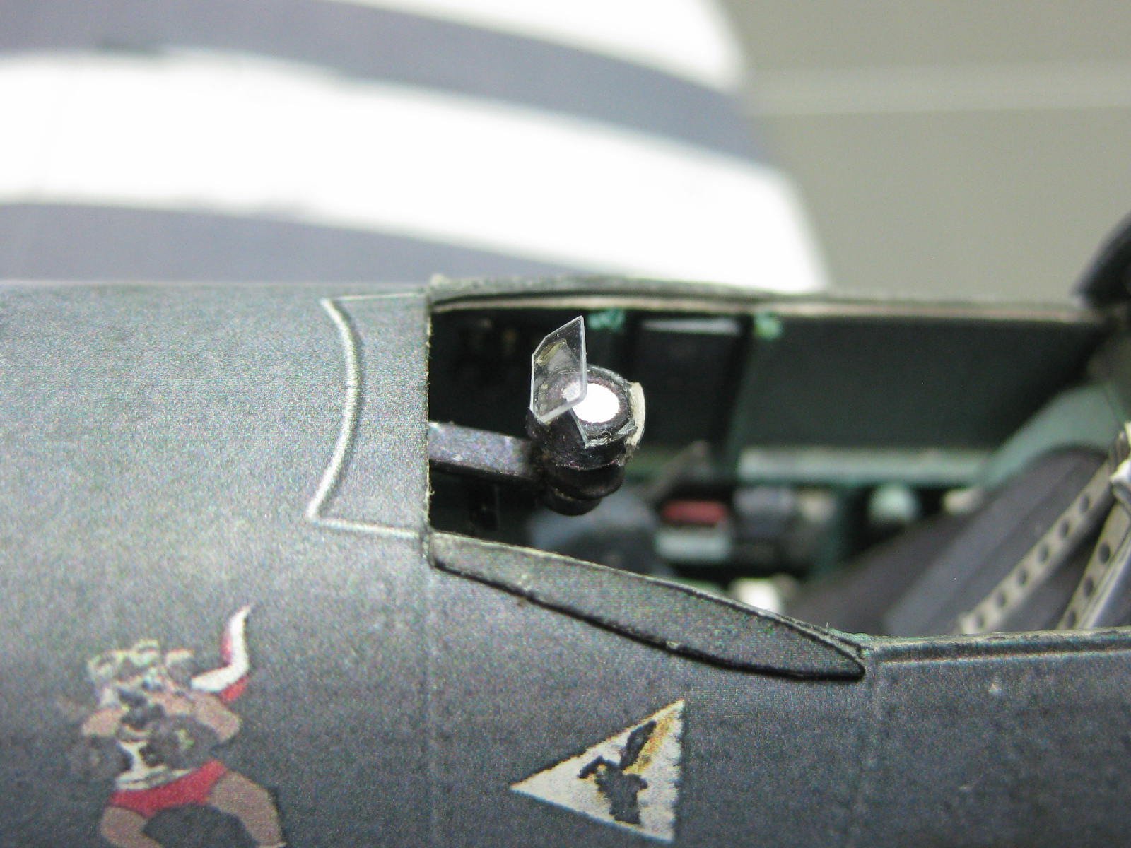
The windscreen :
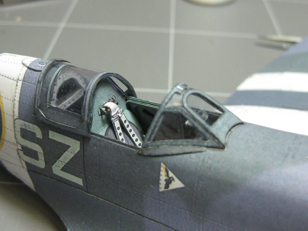
Before fitting the screen I had to fit the bomb-sight :
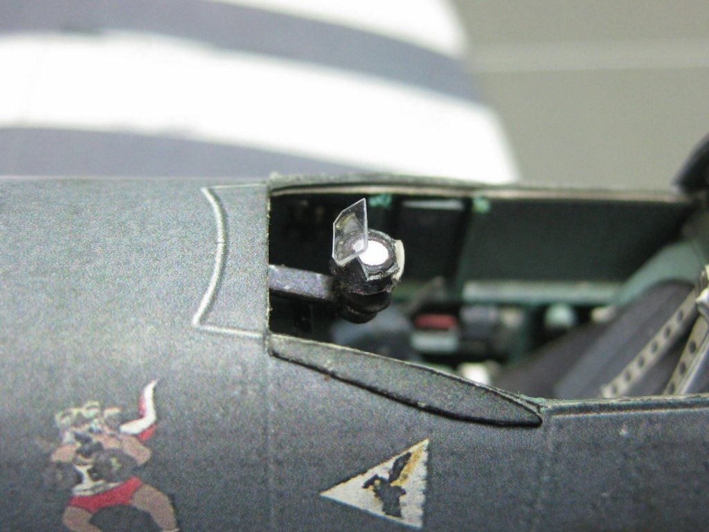
All done :
Danny
- JohnB40, thibaultron, mtaylor and 8 others
-
11
-
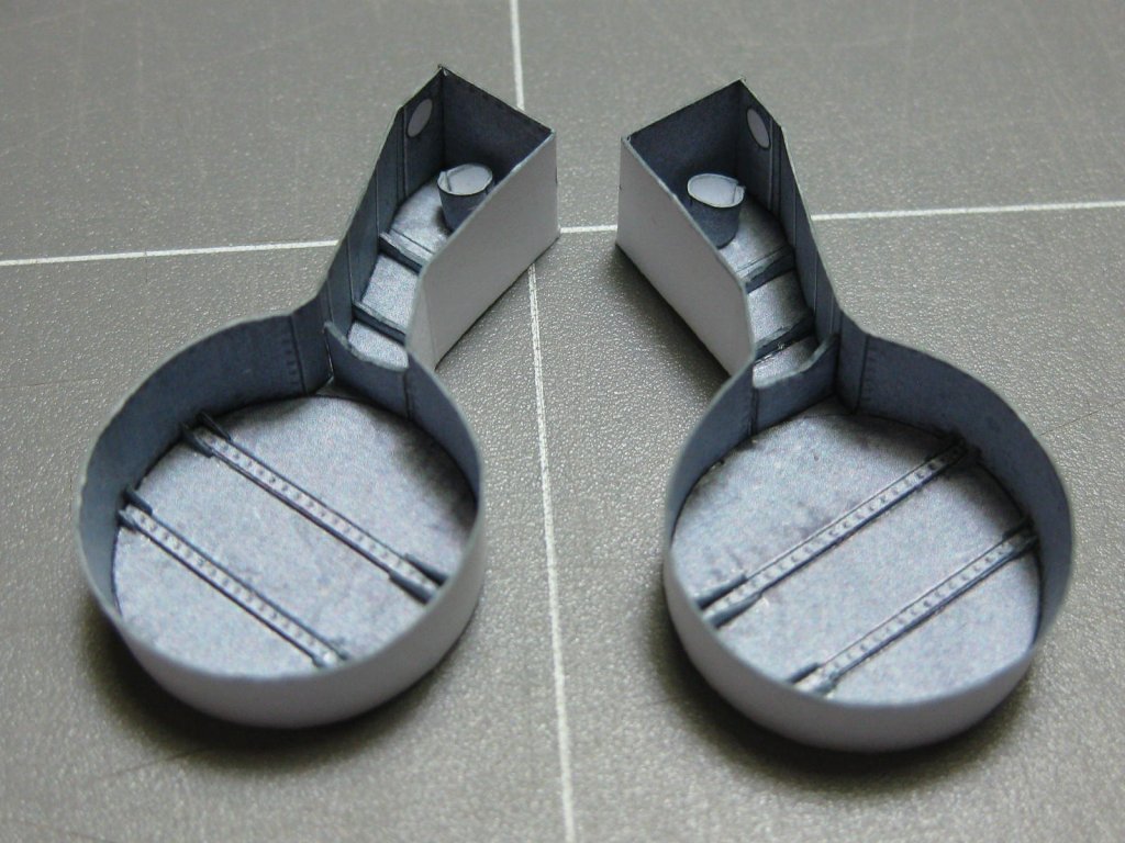
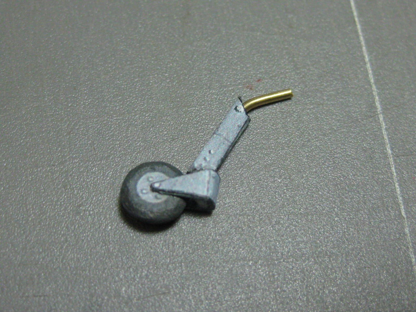
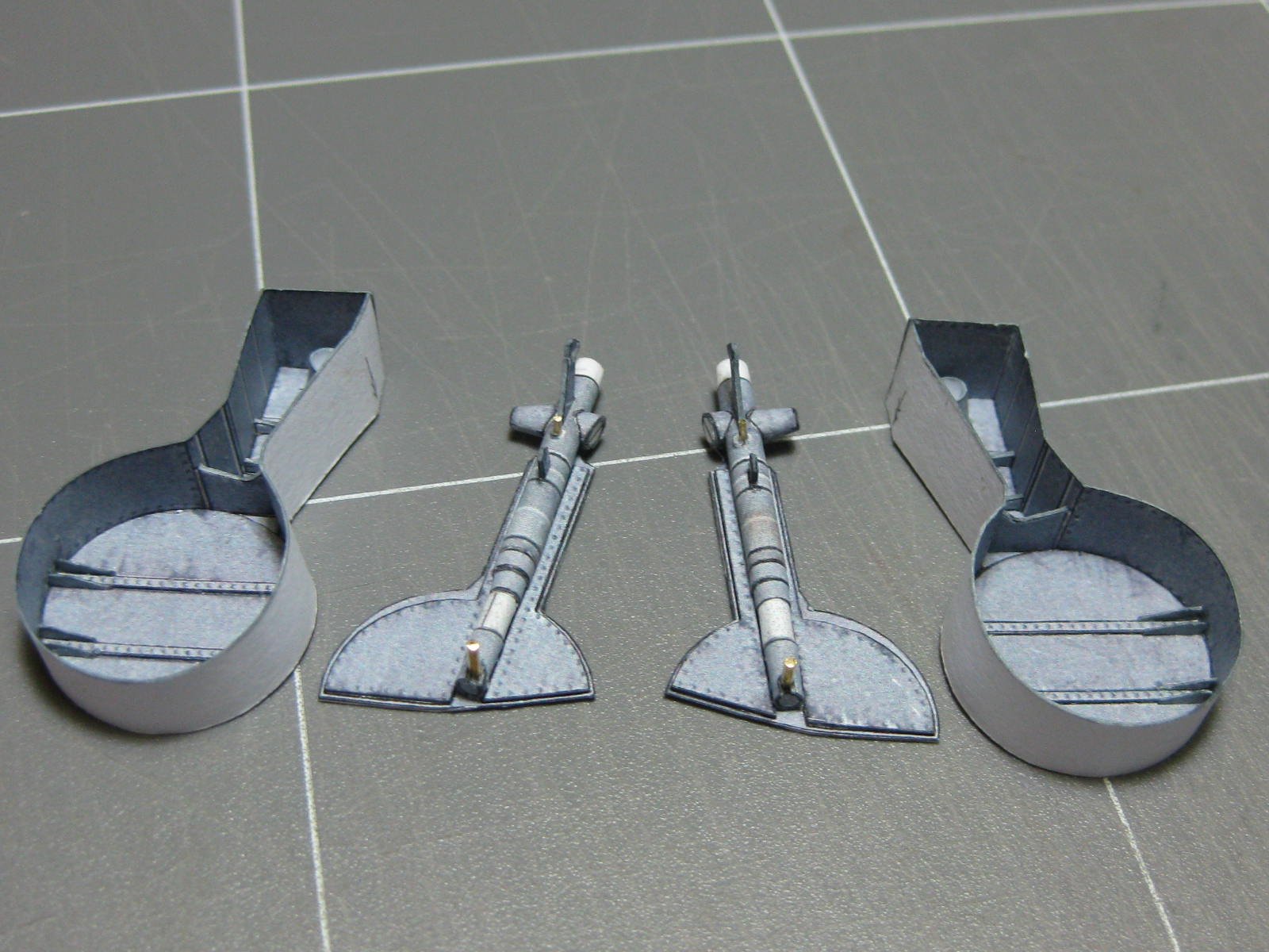
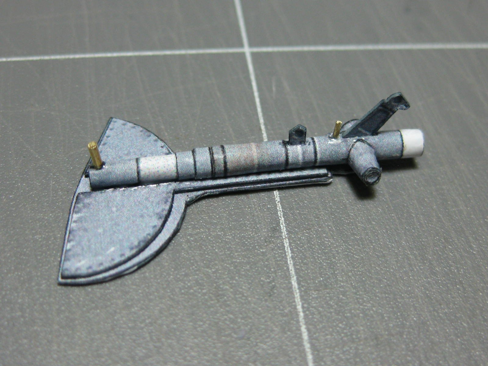
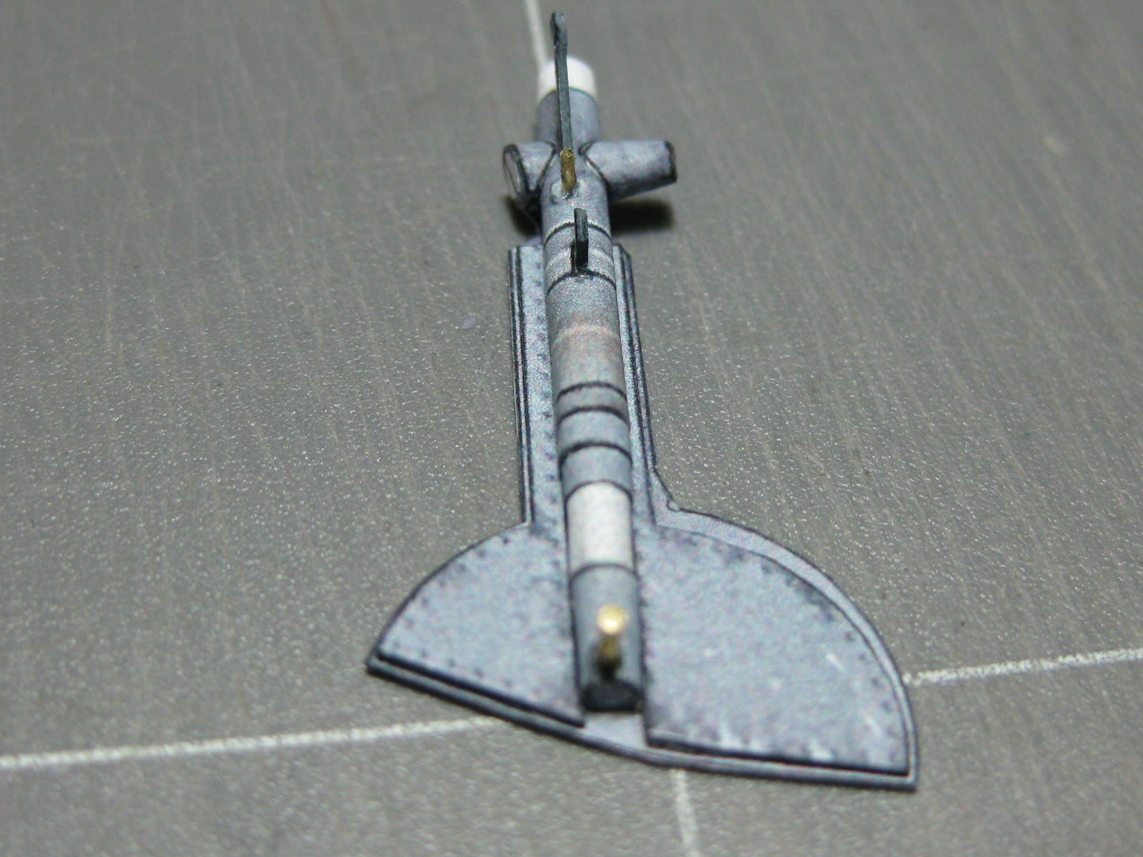
The completed tail-wheel which will be left off until later :
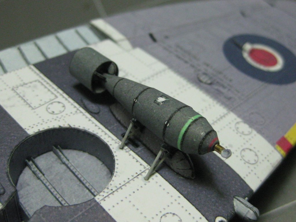
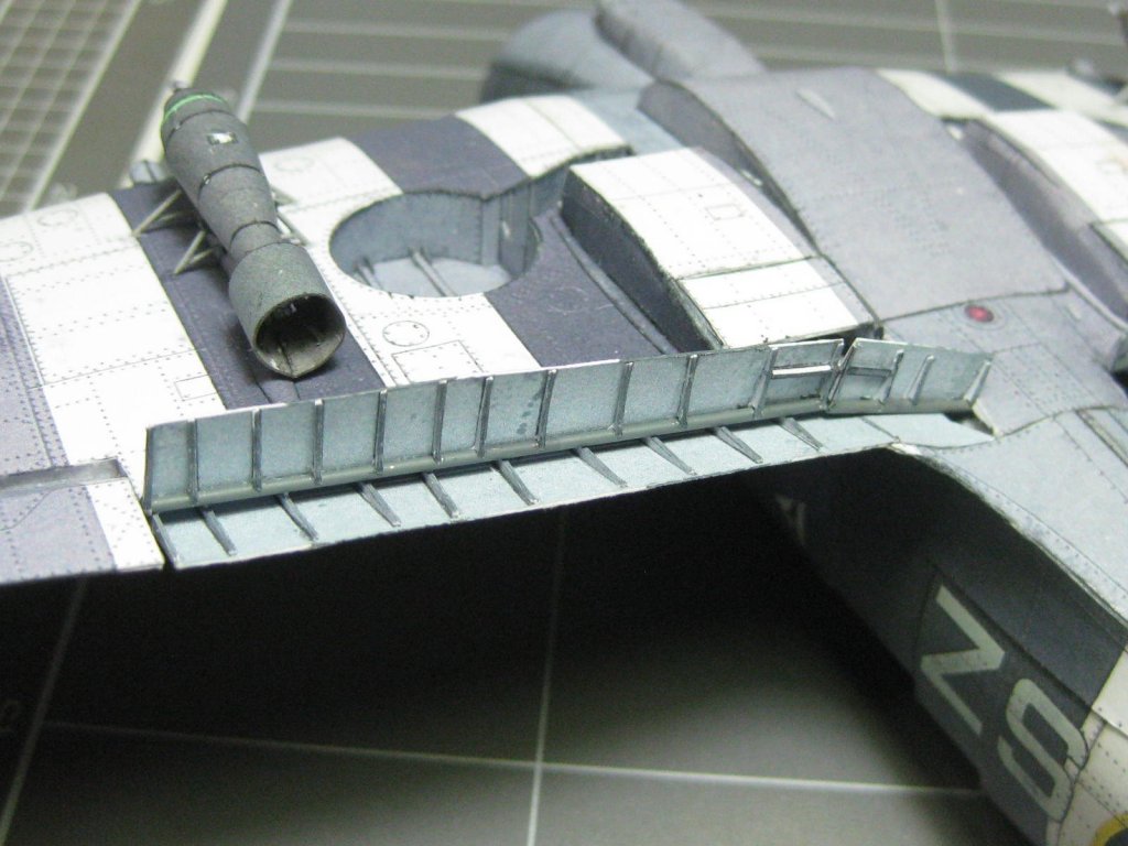
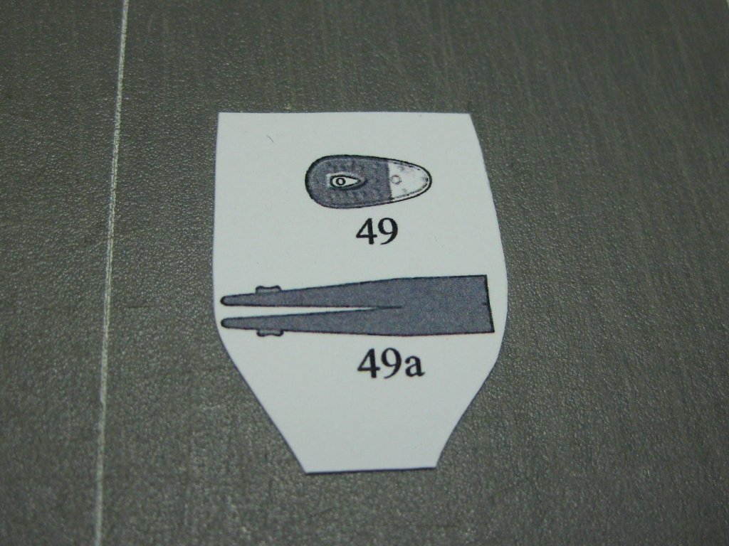
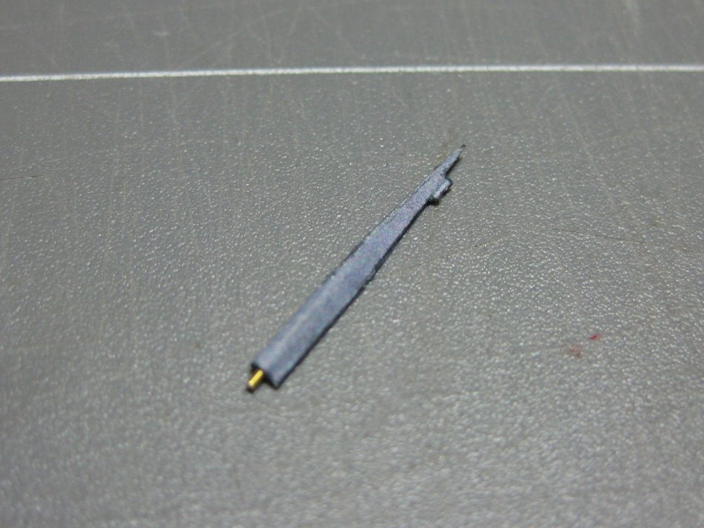
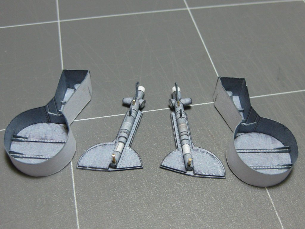
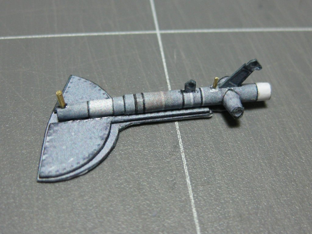
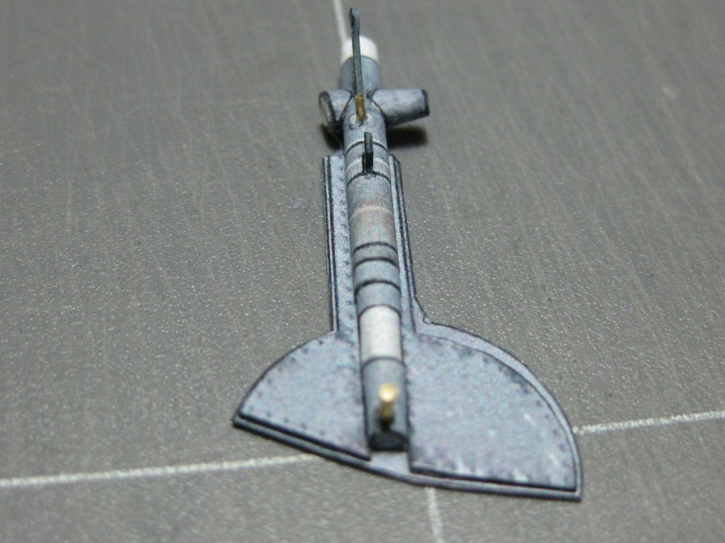
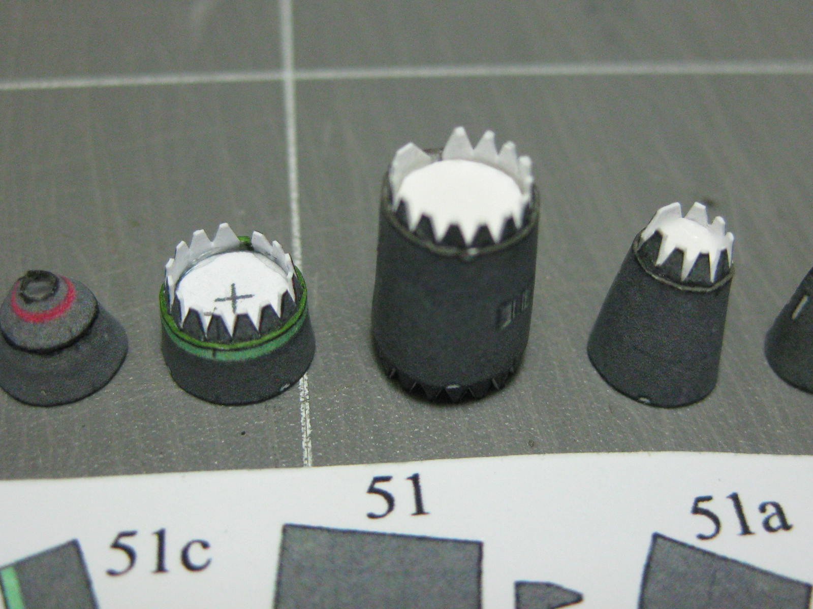
The two wing-mounted bombs and their mounts, another couple of day's work :

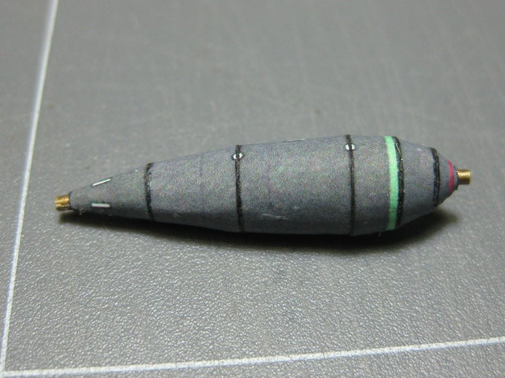
The two "propellors" are rather small and almost invisible when fitted, but why not
:
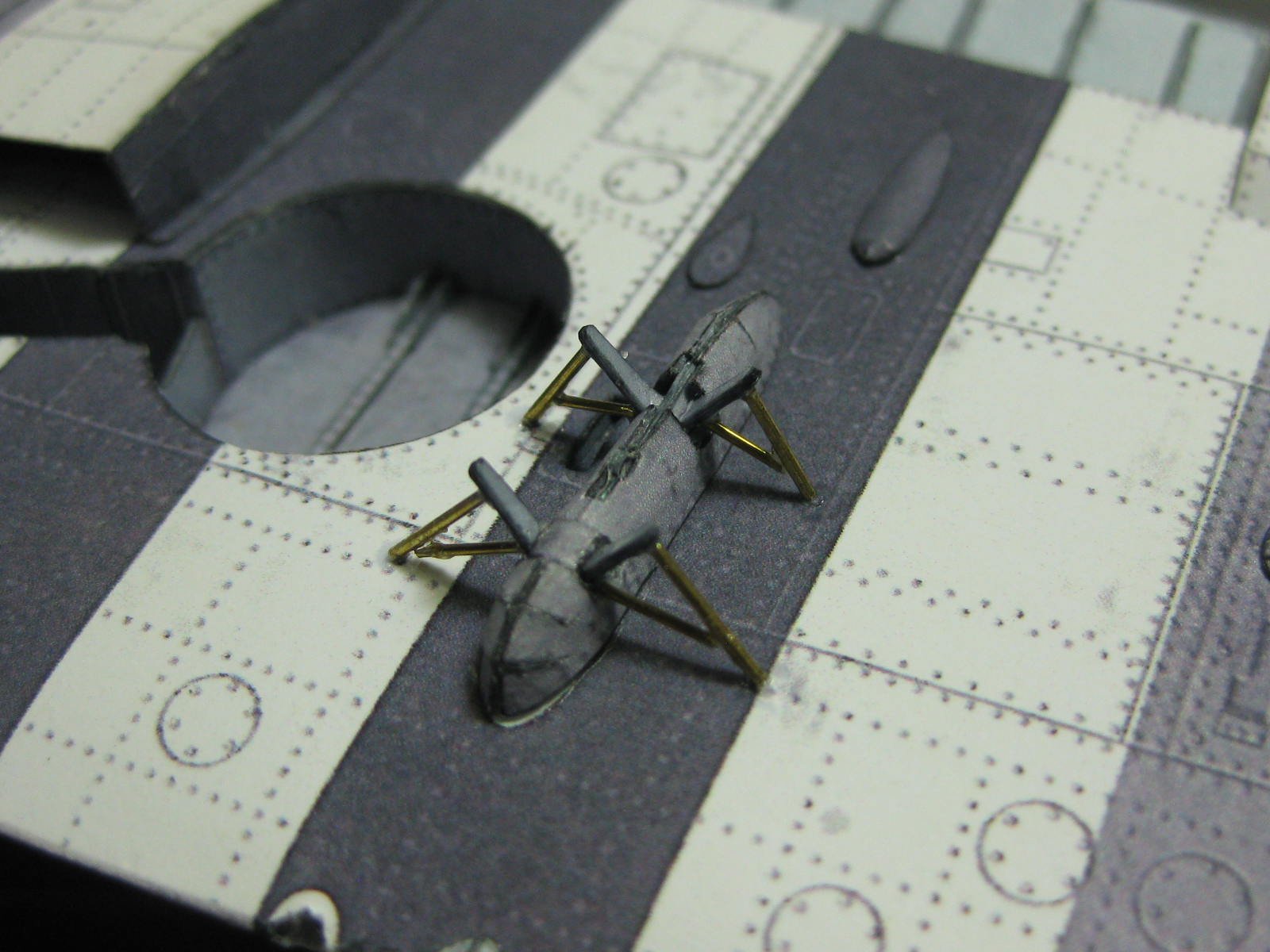
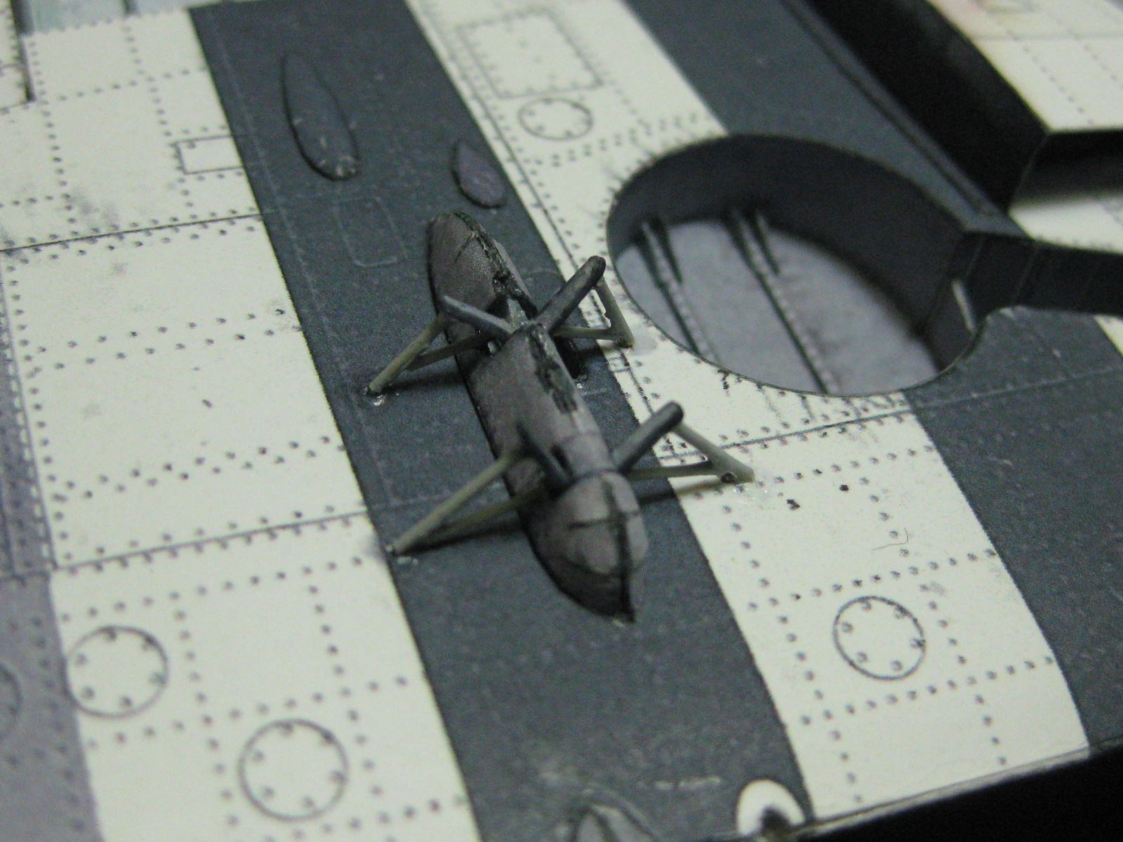
The mounts fitted. A few wire braces to be made and fitted :


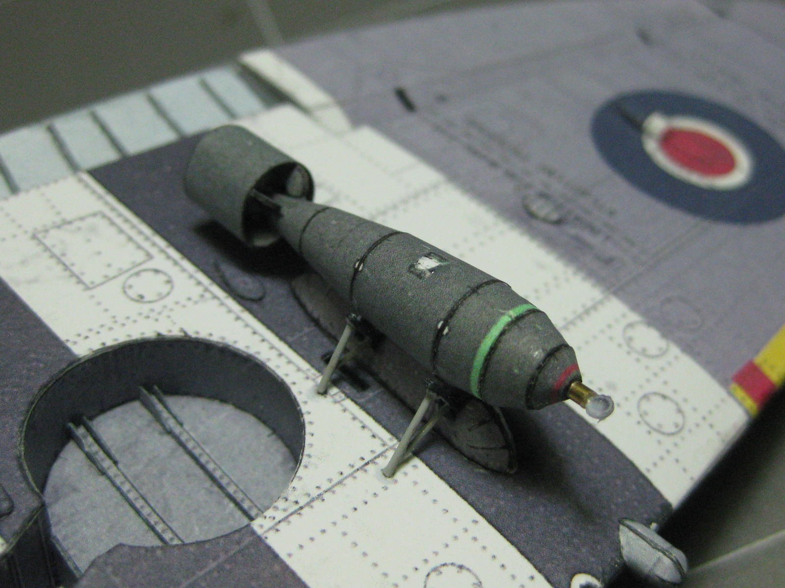
One of the bombs fitted :
Danny
-
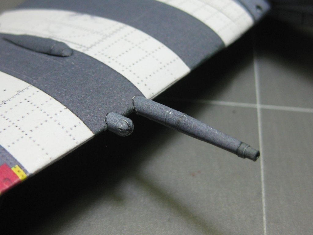
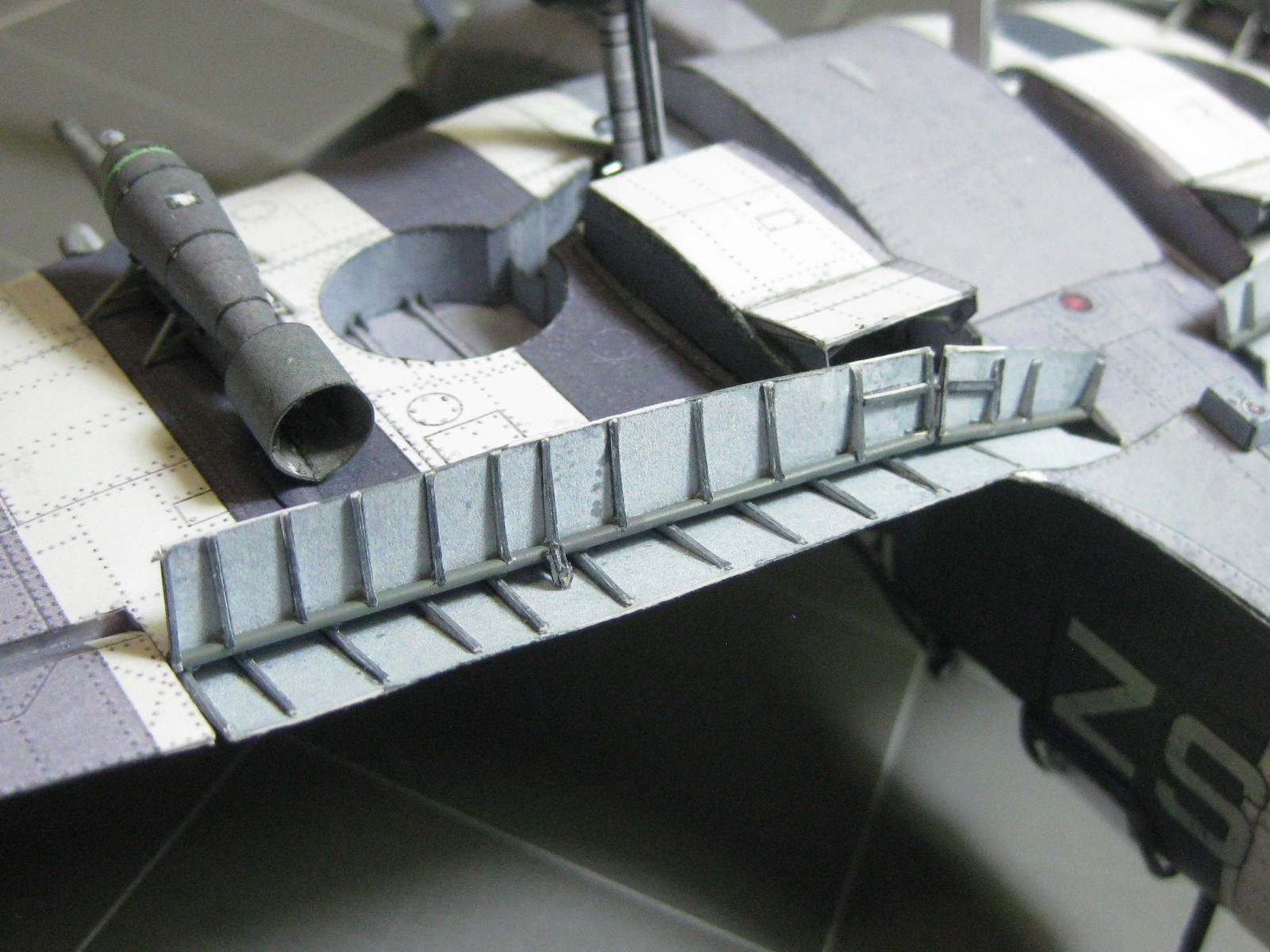
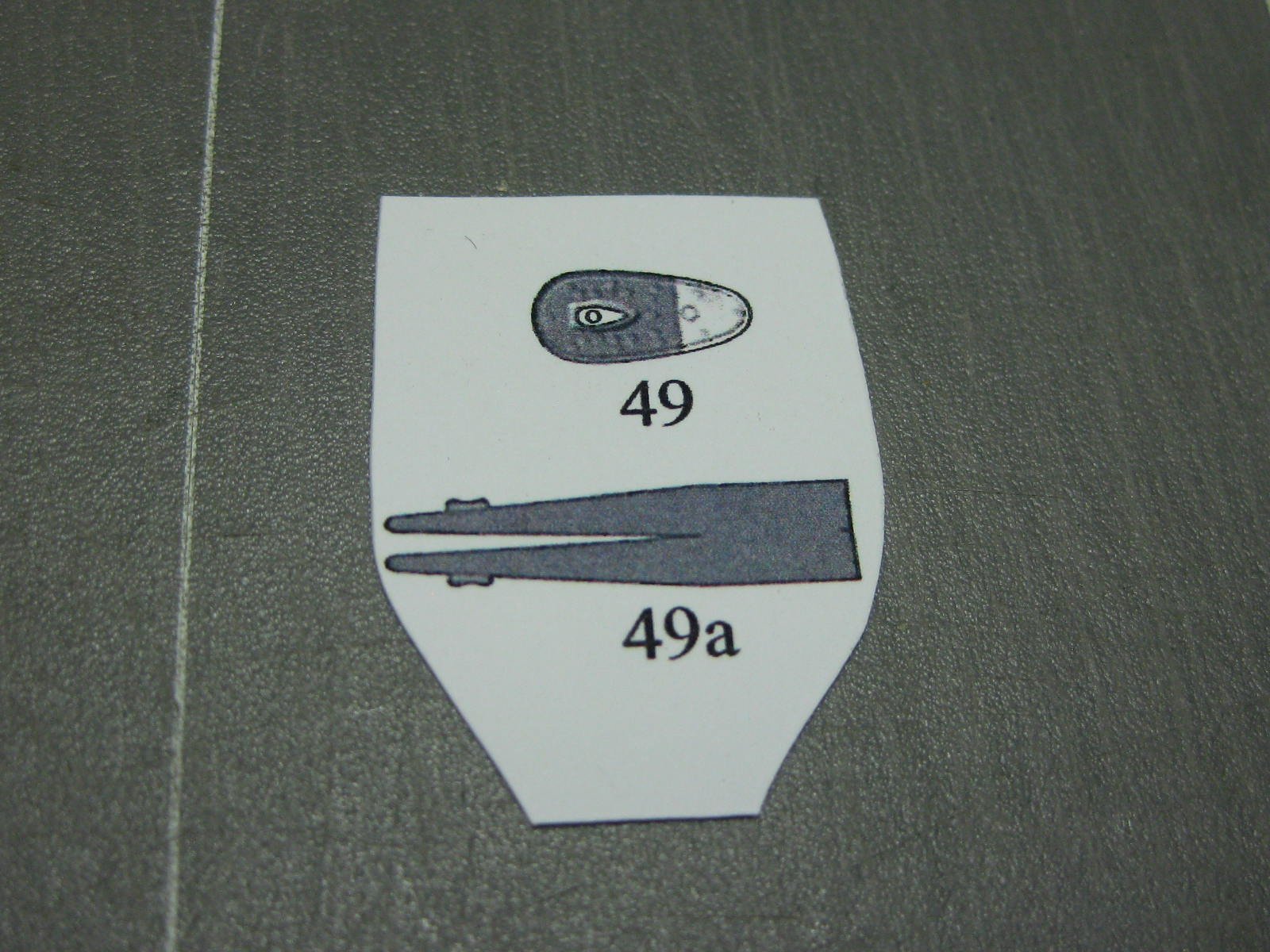
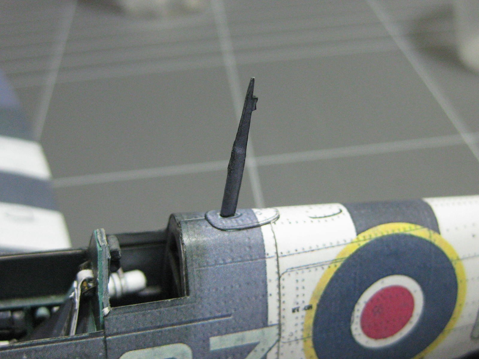
There are quite a few small details left to make. A lot of these will be left off until they are safe to fit. The radio aerial :

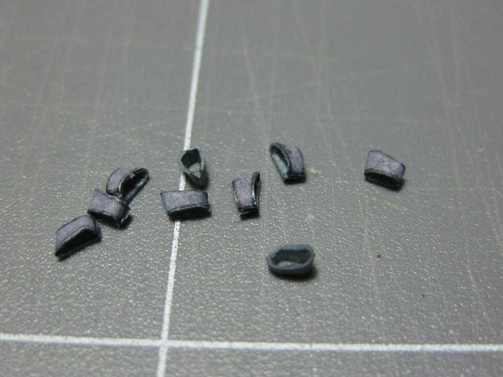
The wing cannons. These are rolled around a 0.5mm wire for strength :
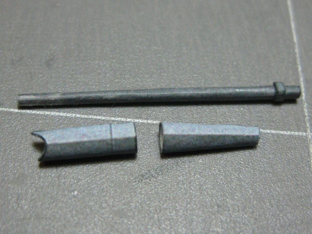
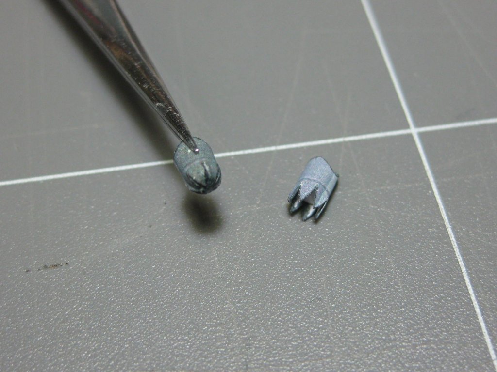
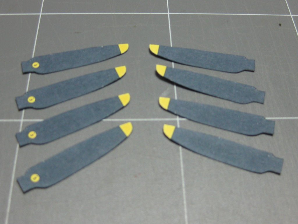
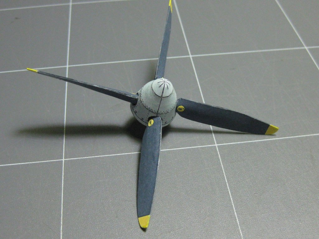
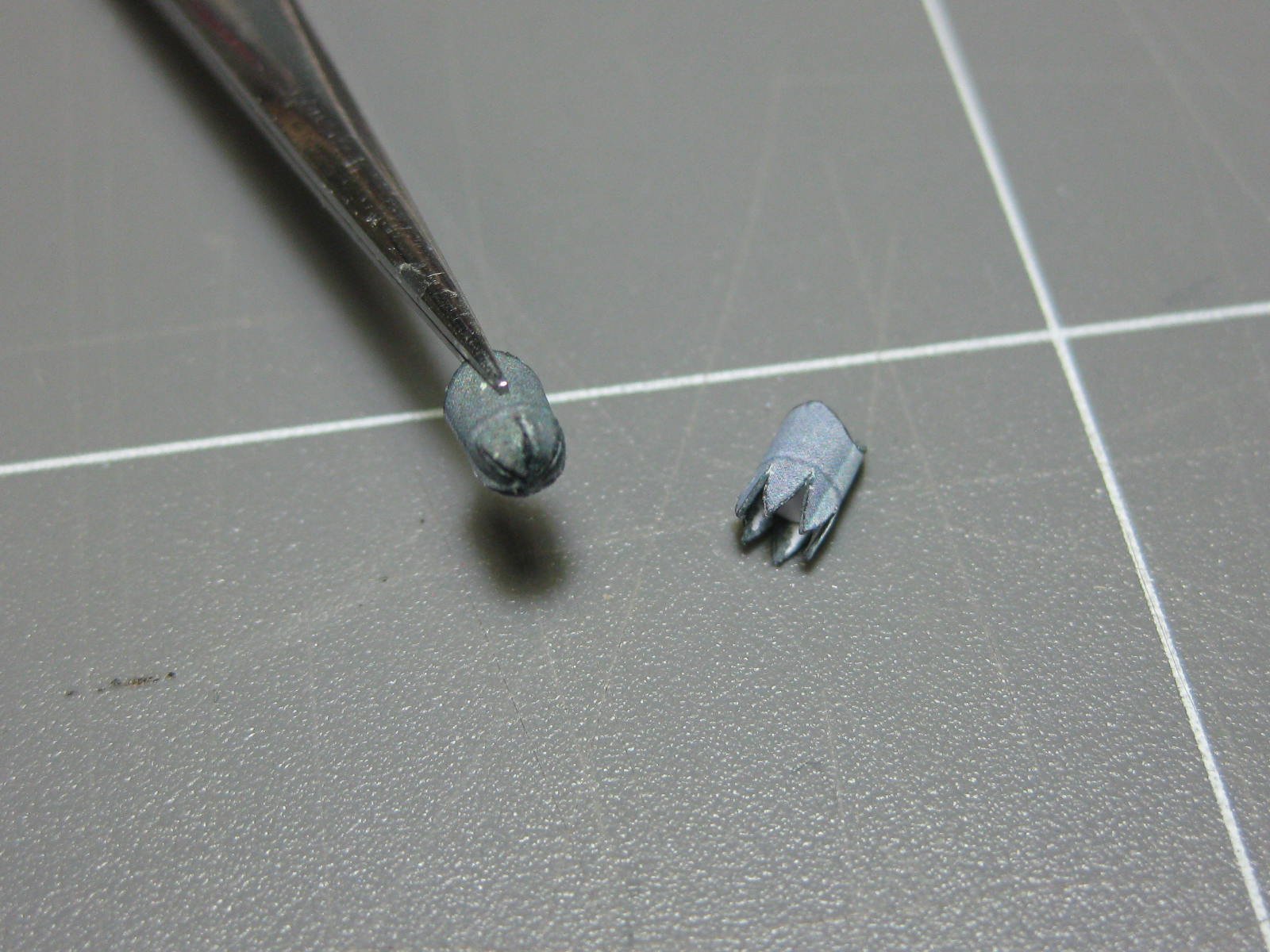
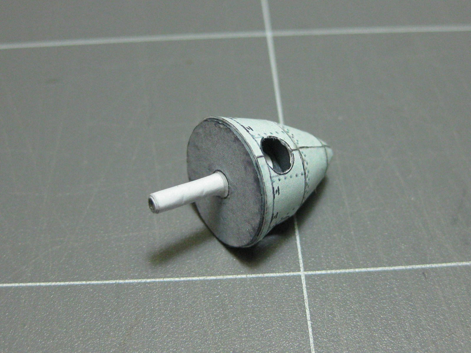
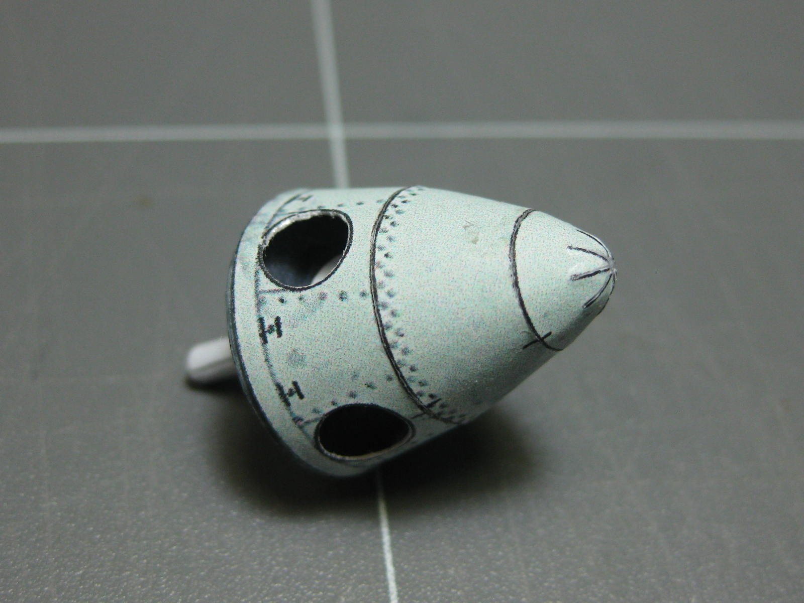
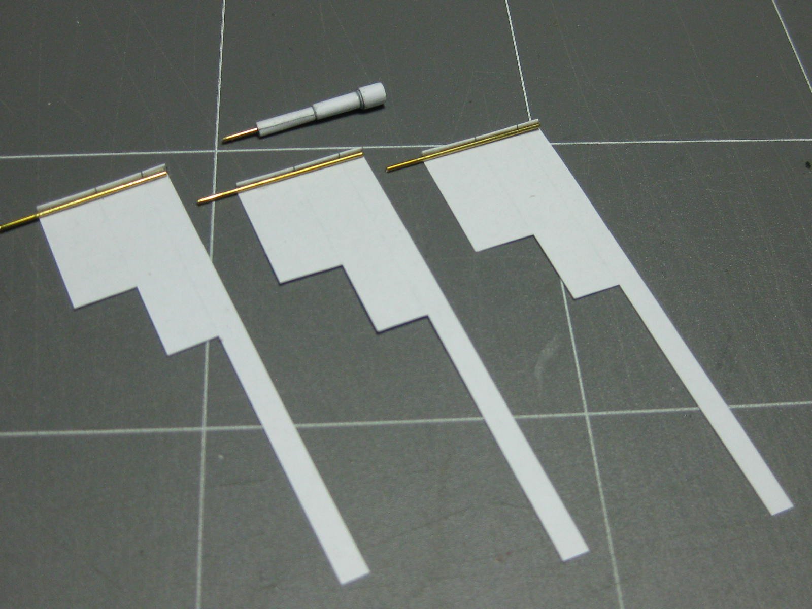
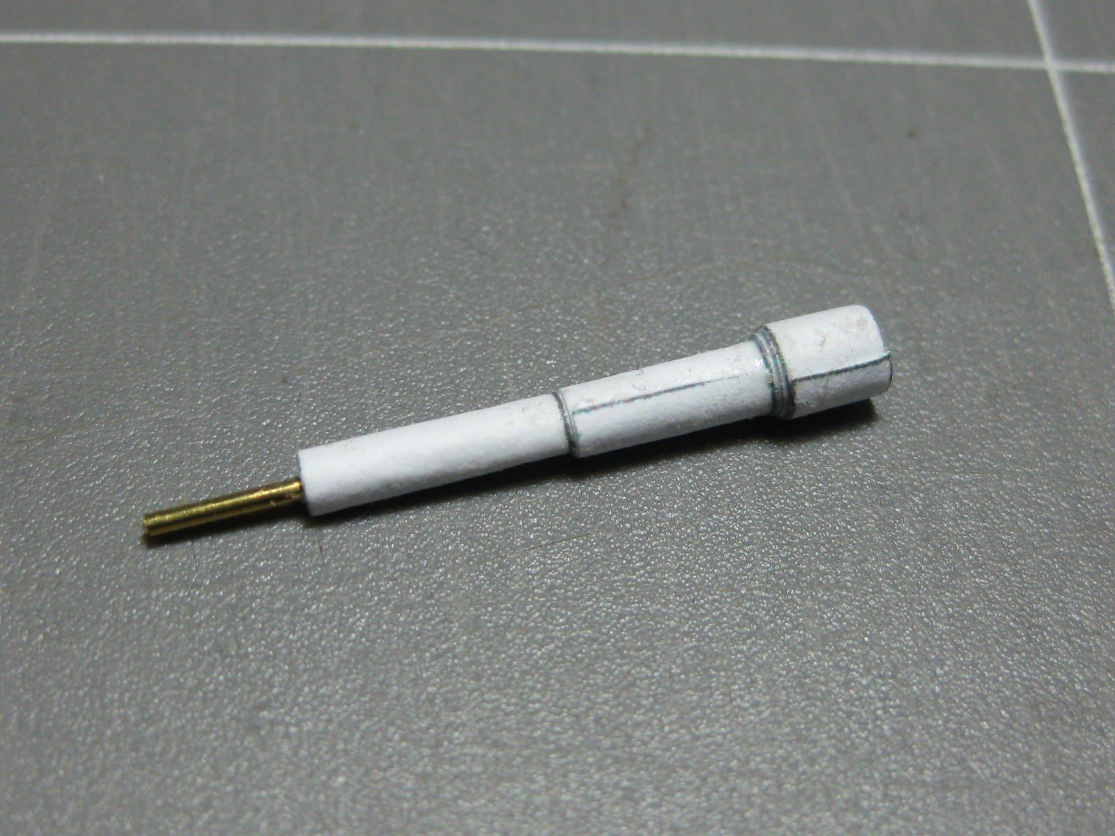
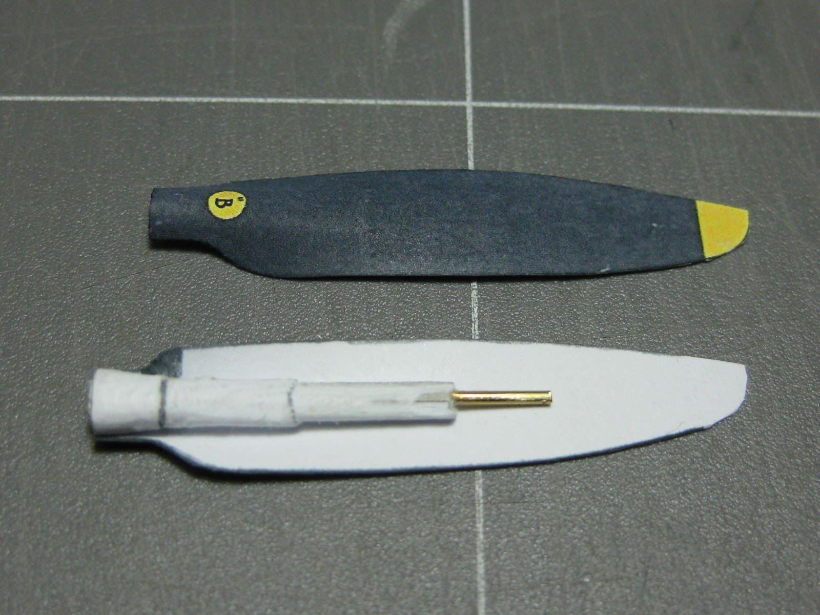
The propellor and spinner took nearly two days to make :
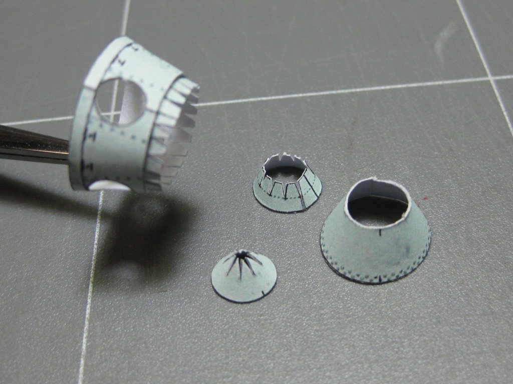
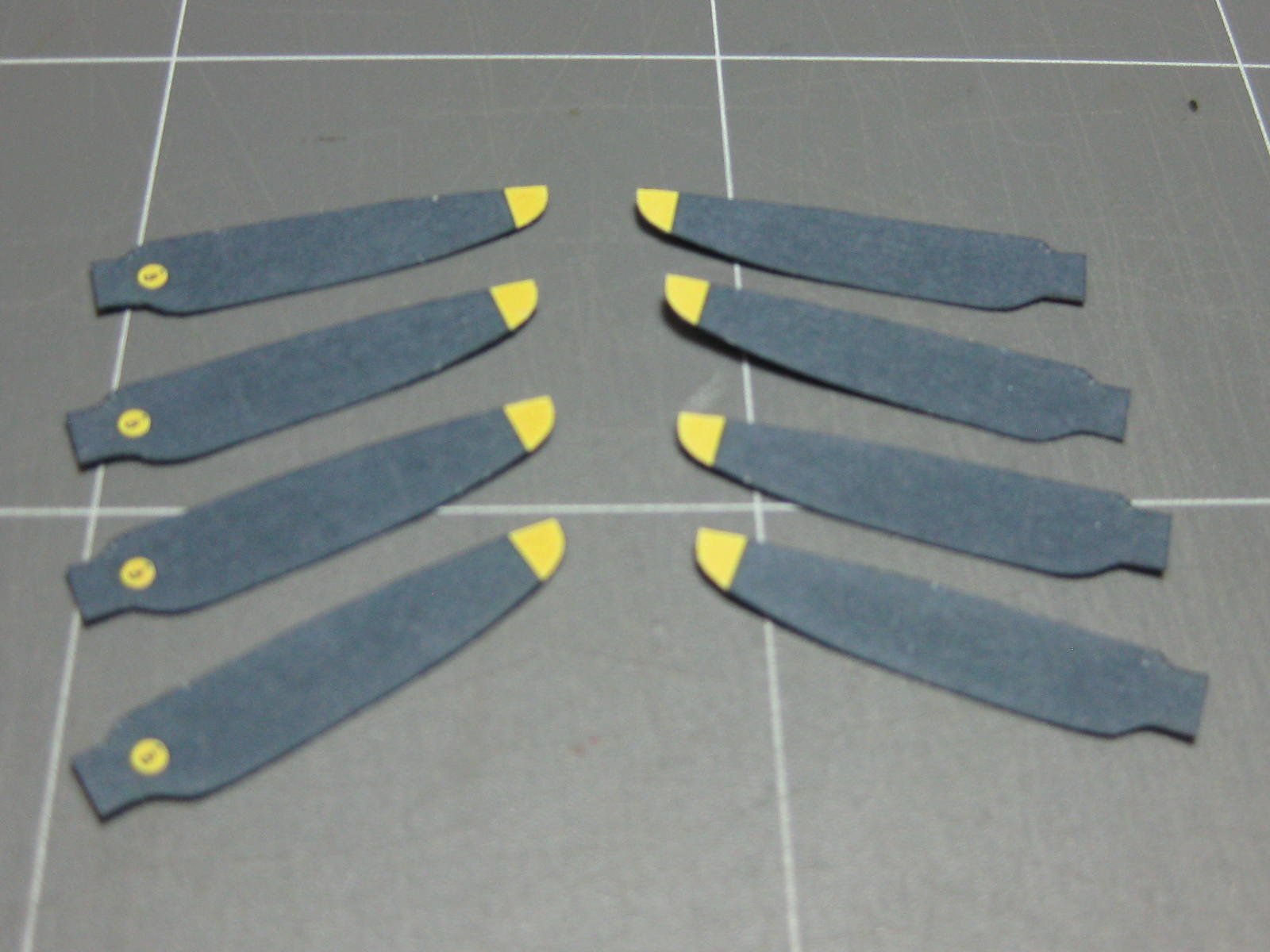
The blades are reinforced with a paper tube wrapped around a wire and shaped to fit :

Danny
- mtaylor, thibaultron, GrandpaPhil and 8 others
-
11
-
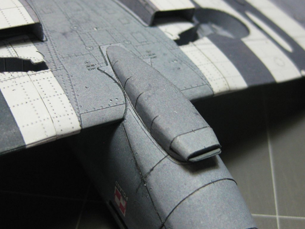
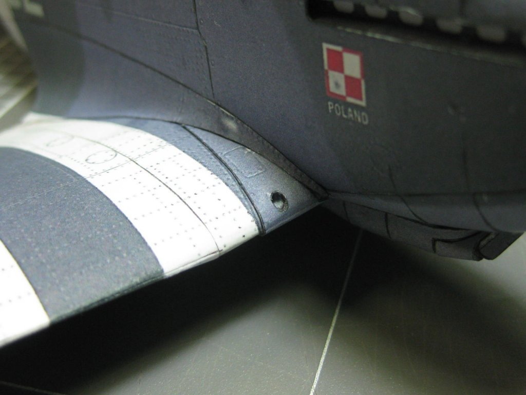
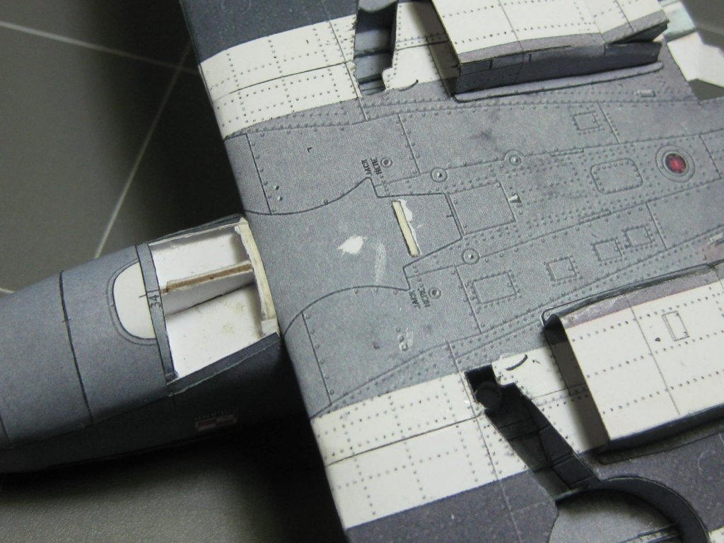
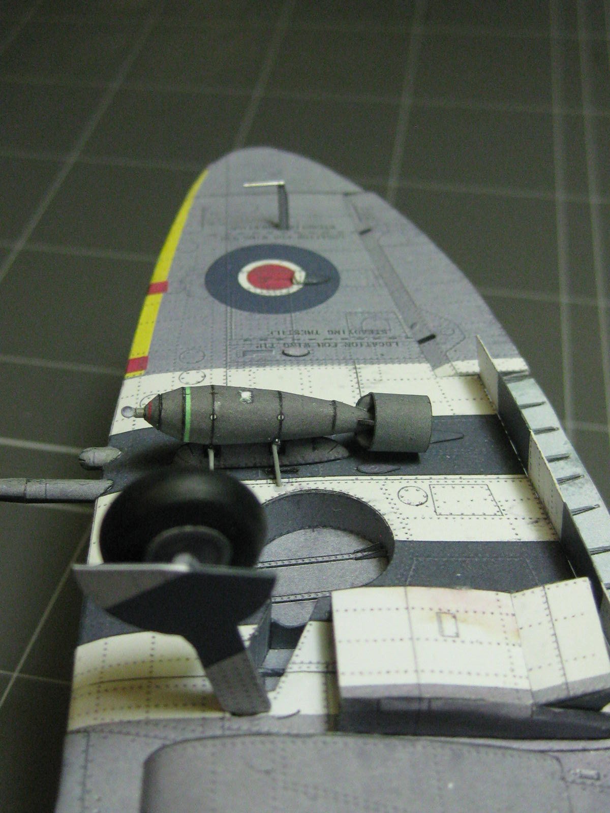
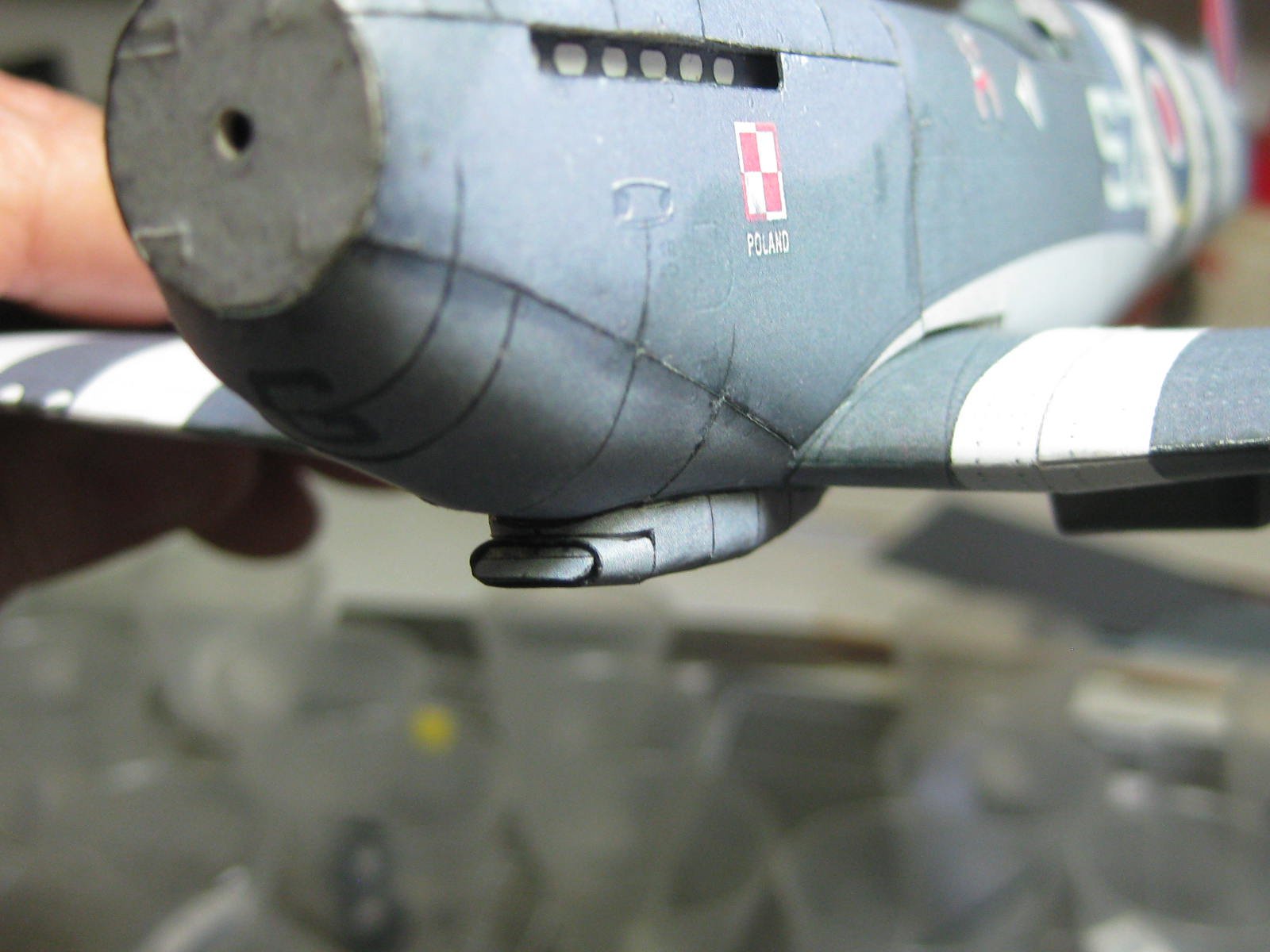
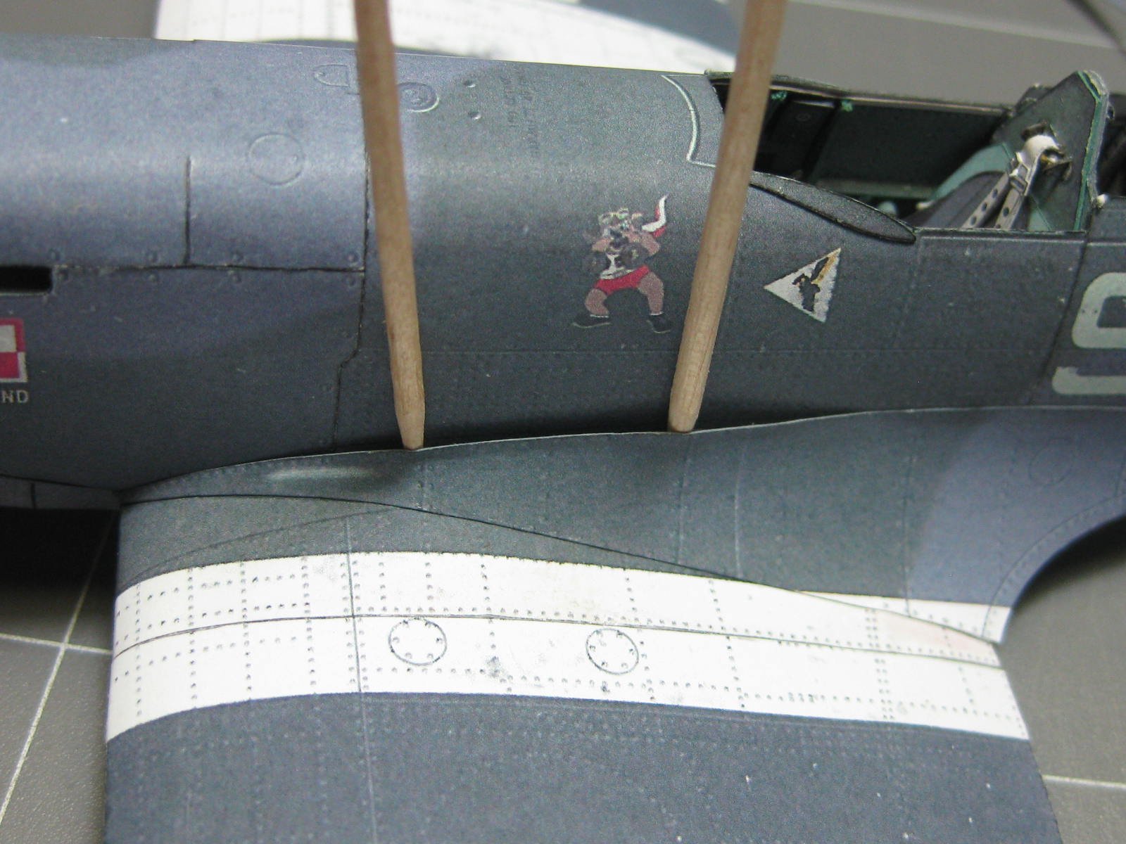
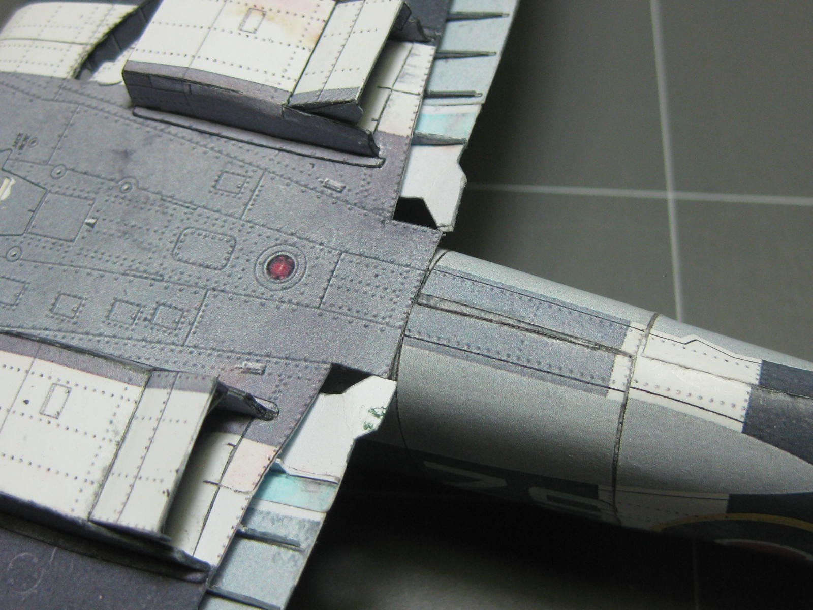
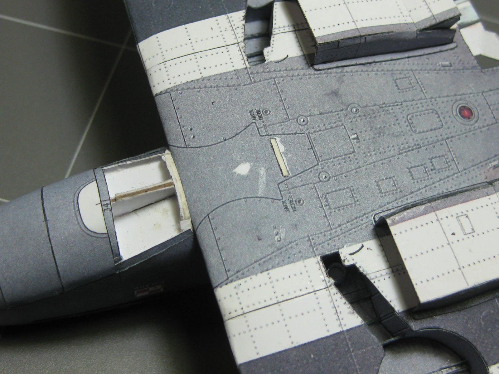
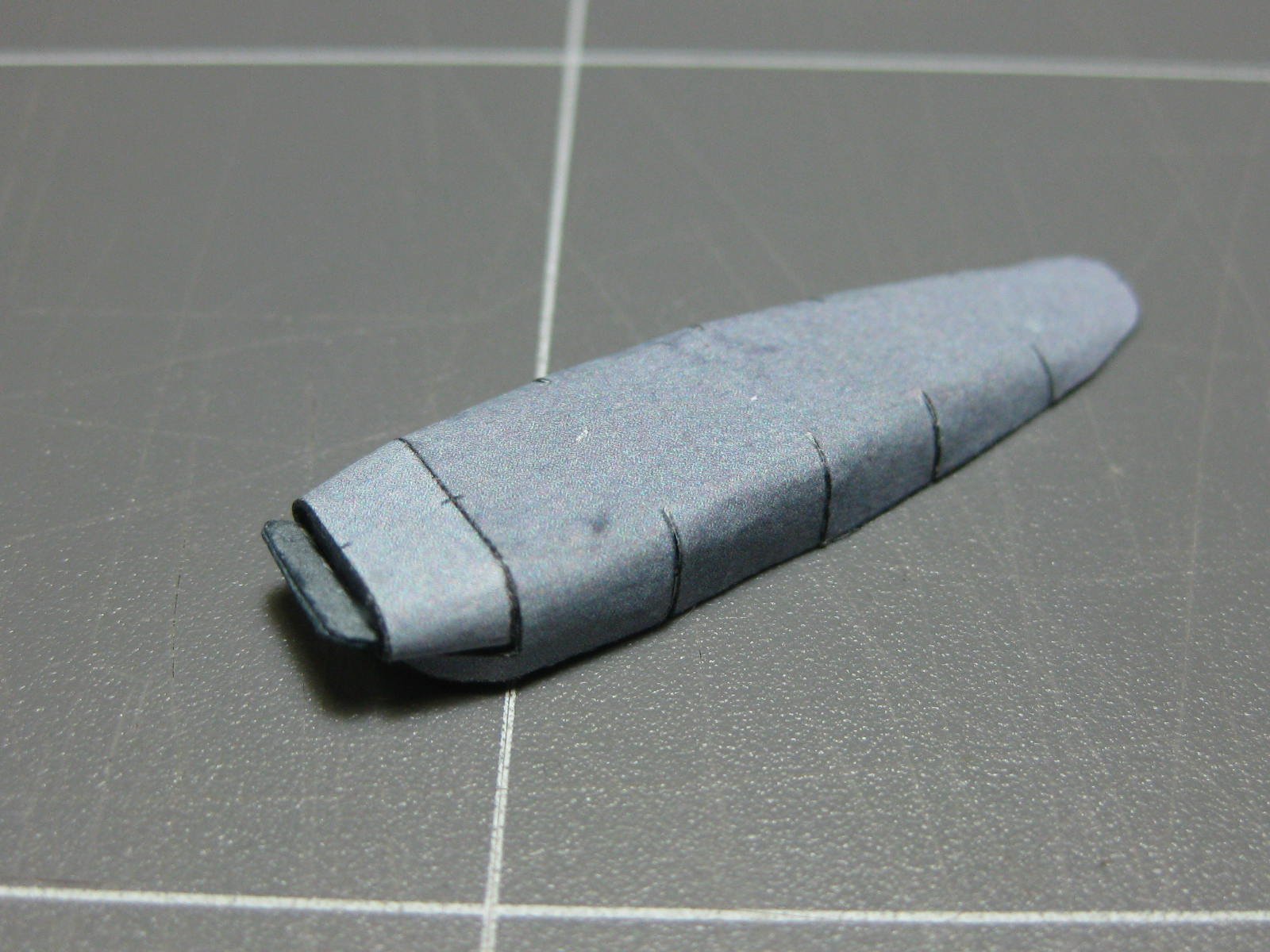
The air scoop took me most of a day to make. Some of those joins look bad in the pics, but a lot better in real life. I'll touch them up a bit when I've finished everything else :

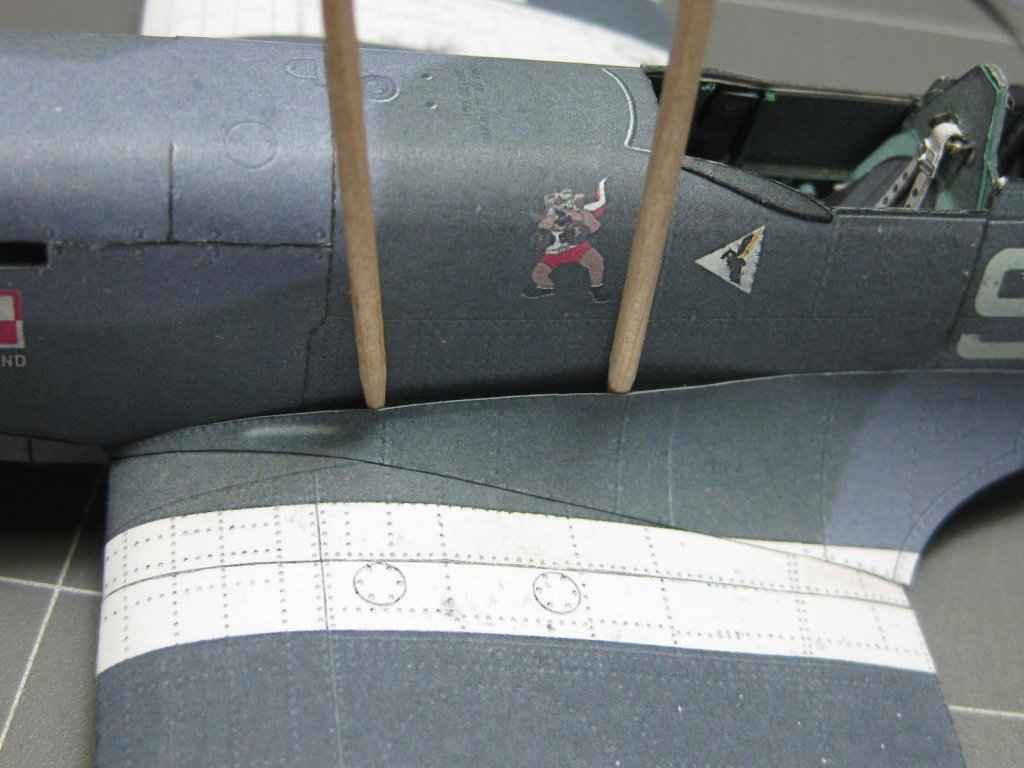
The wing fillets did fit perfectly
. They were also not too difficult to fit. I used toothpicks to hold them out from the fuselage while I applied glue :
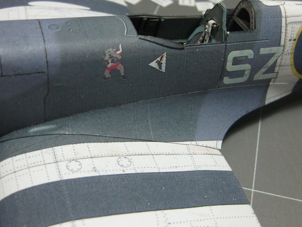
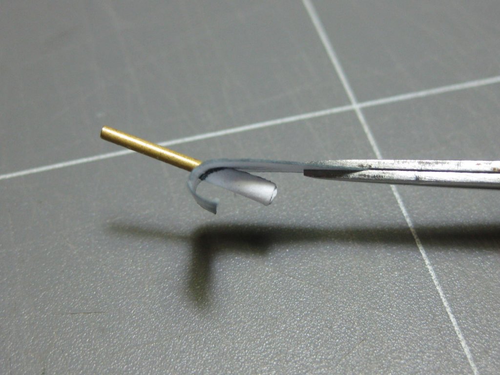
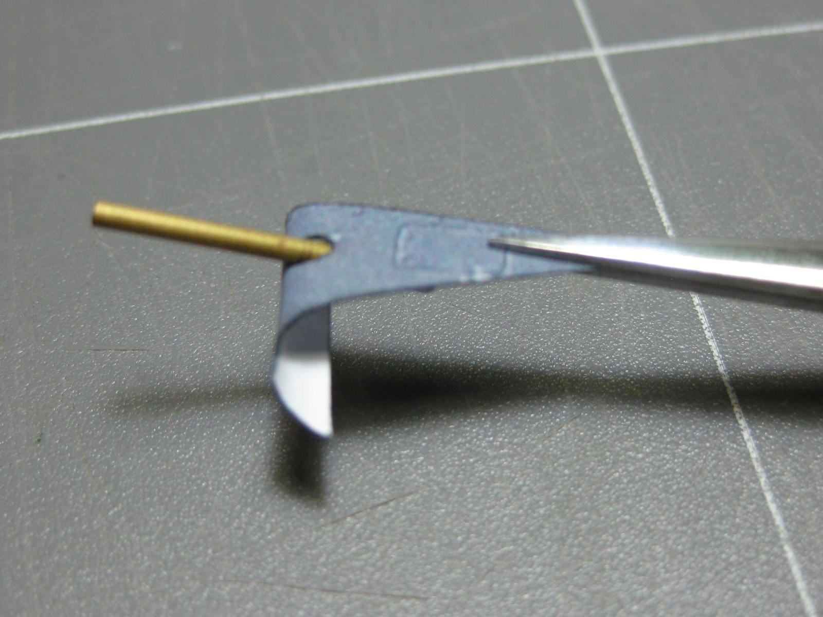
There is a small fillet on the leading edge of the right wing which has a tube fitted (I don't know what it's actually for). Here's how I fitted it. The brass wire locates it in the panel while gluing :

It's time to fit the first half of the exhaust pipes. The outer ones will be fitted later to avoid damage :
Danny
- mtaylor, druxey, GrandpaPhil and 5 others
-
8
-
21 minutes ago, GrandpaPhil said:
Dan,
What kind of glue do you use for your card models?
Phil
"Mont-Marte" brand acid-free white PVA craft glue. It's fairly thick and dries clear and quickly. Other brands may be similar, but the acid-free part is essential as it doesn't smear Ink-Jet printed paper.
Danny
-
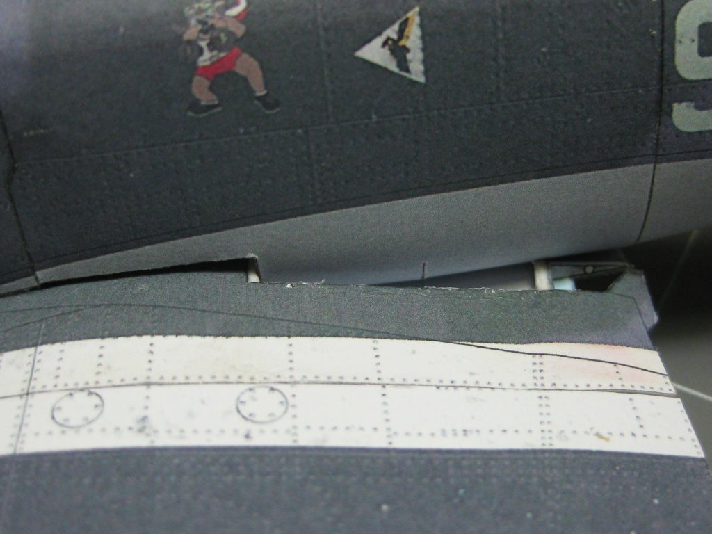
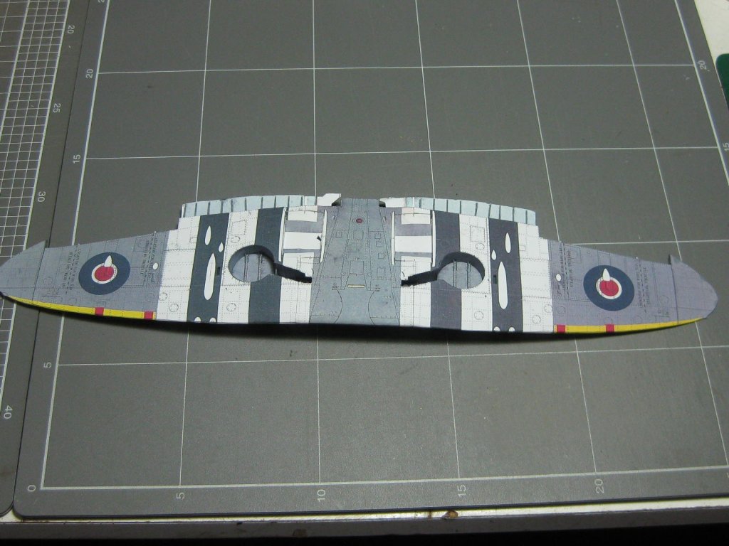
Now came the time to fit the wings and fuselage together. This looked rather scary when I first dry-fitted them, as the fit looked WAY off. However there are fillets to be added later between them which will cover the gaps perfectly. I cut these out and tried them before applying any glue to make sure everything was in fact OK - which it should be (we'll see
") ):
):

Danny
- Canute, druxey, GrandpaPhil and 4 others
-
7
-
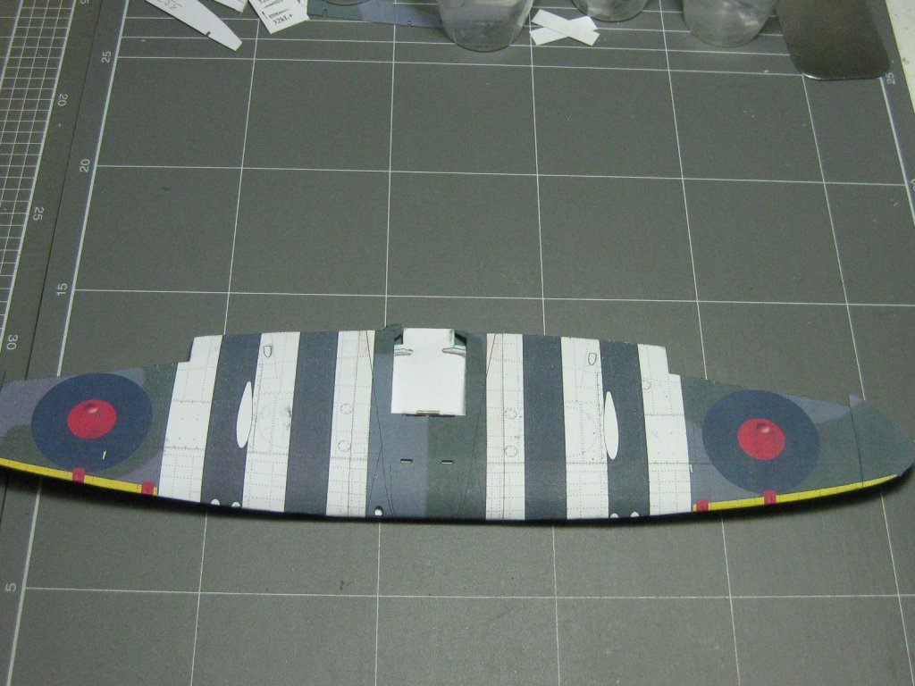
There are a few small details under the wings that are best fitted now before I attach the wings to the fuselage. The kit gives you the option of either gluing a flat piece on or making and fitting a rounded one :
Naturally I opted for the rounded ones
:

I also made the intake scoop, even though it gets fitted after the wings are on. This uses a very small framework, which would have been nice to have as laser-cut but I had to make it from laminated card - lots of rather difficult cutting :

Danny
-
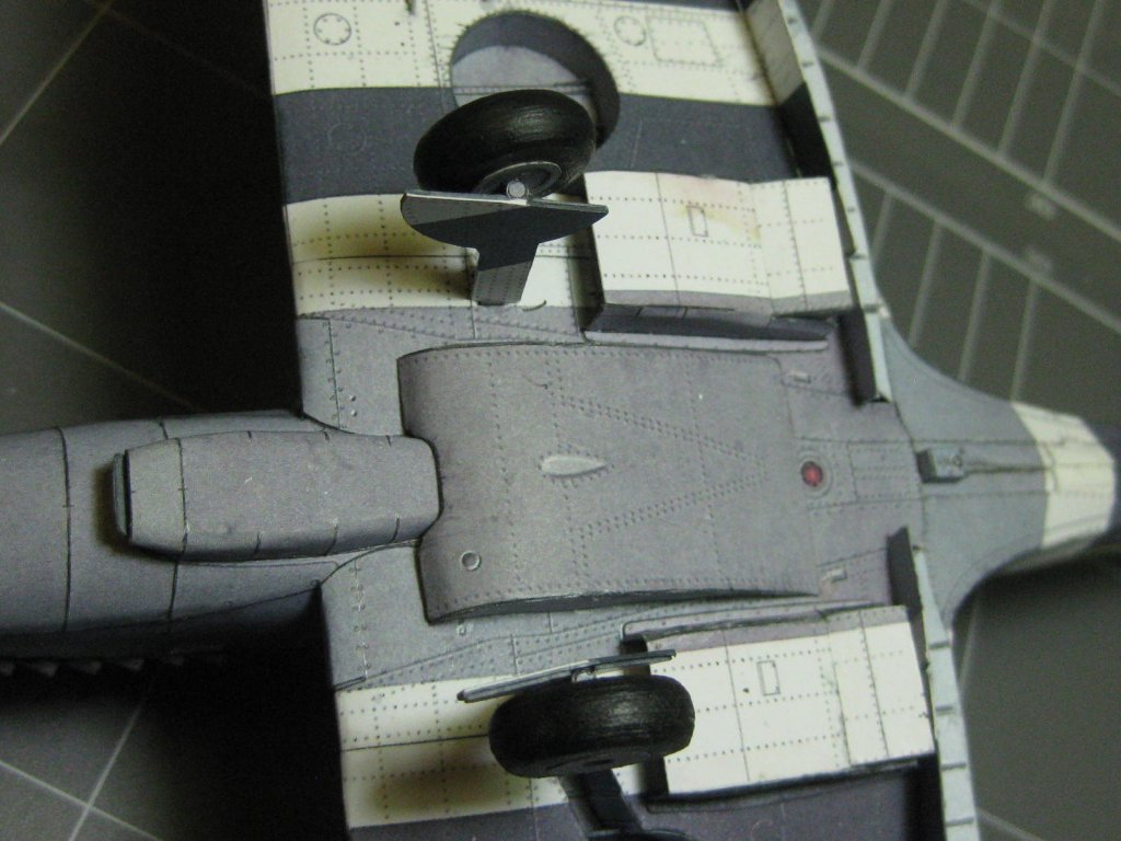
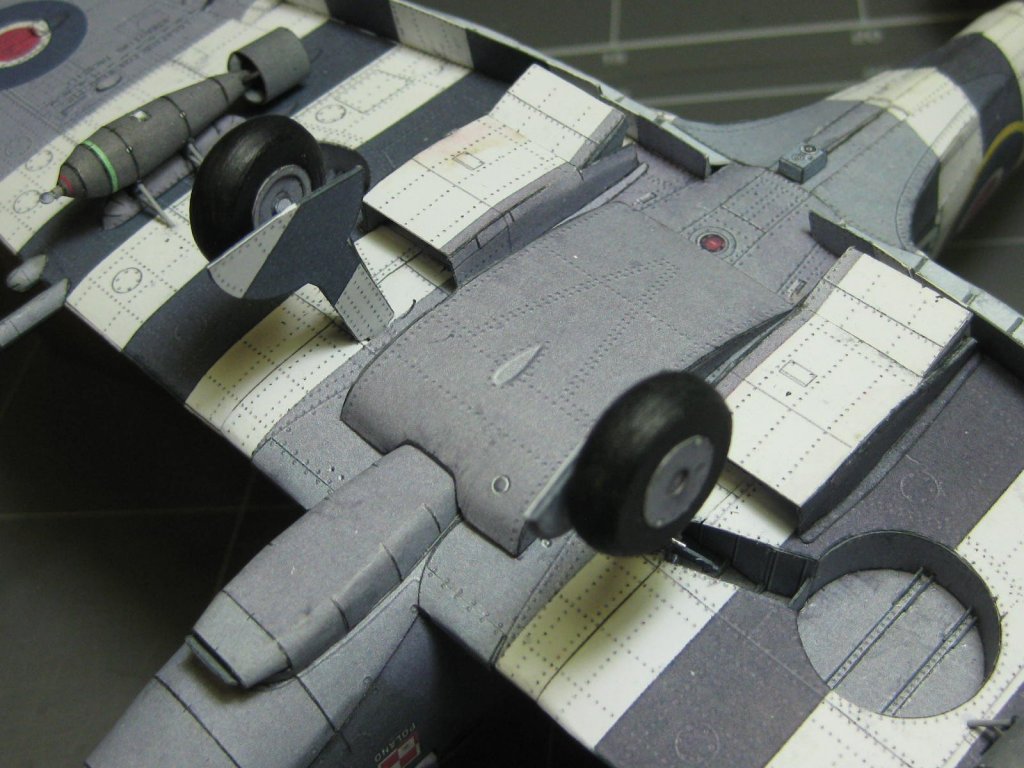
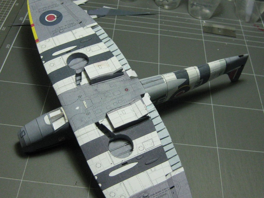
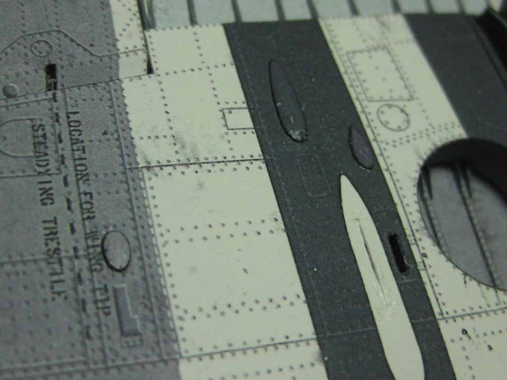
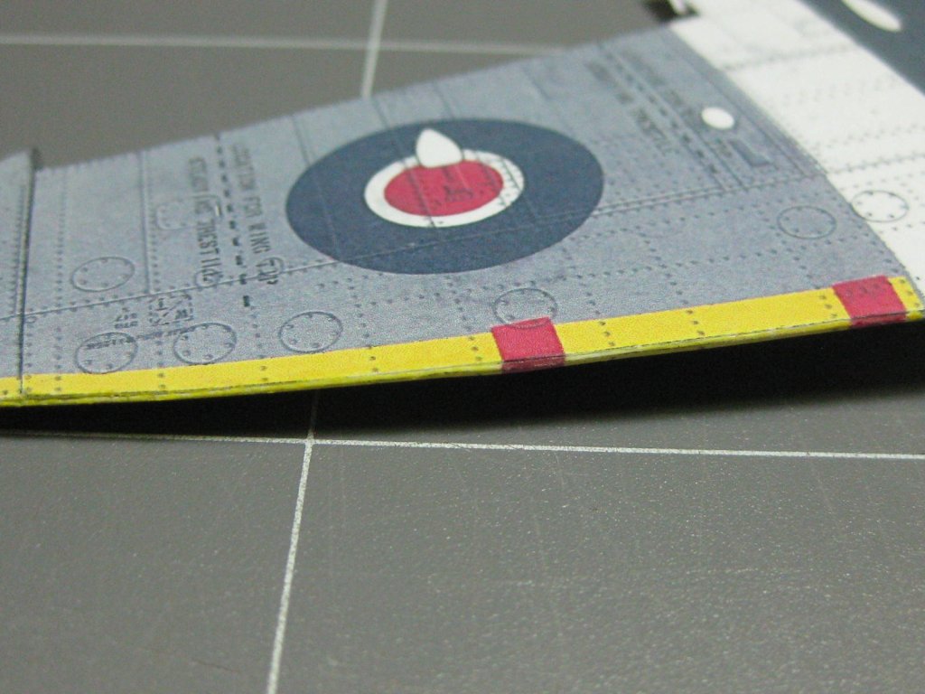
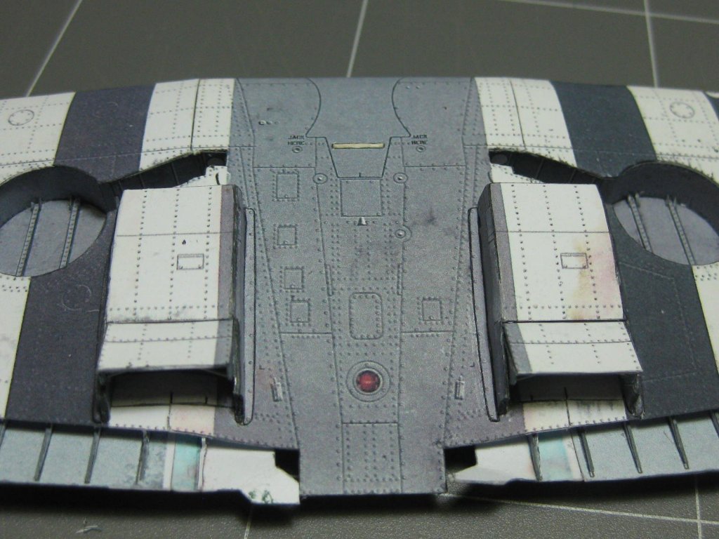
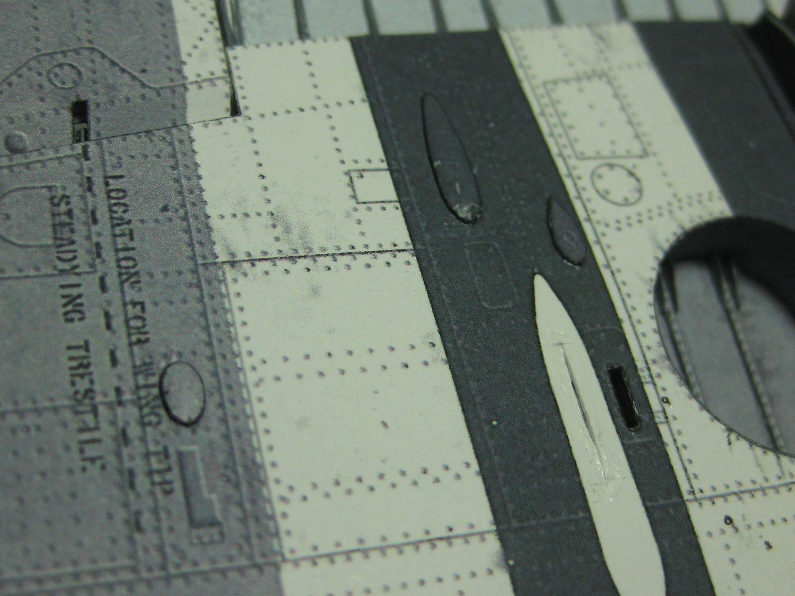
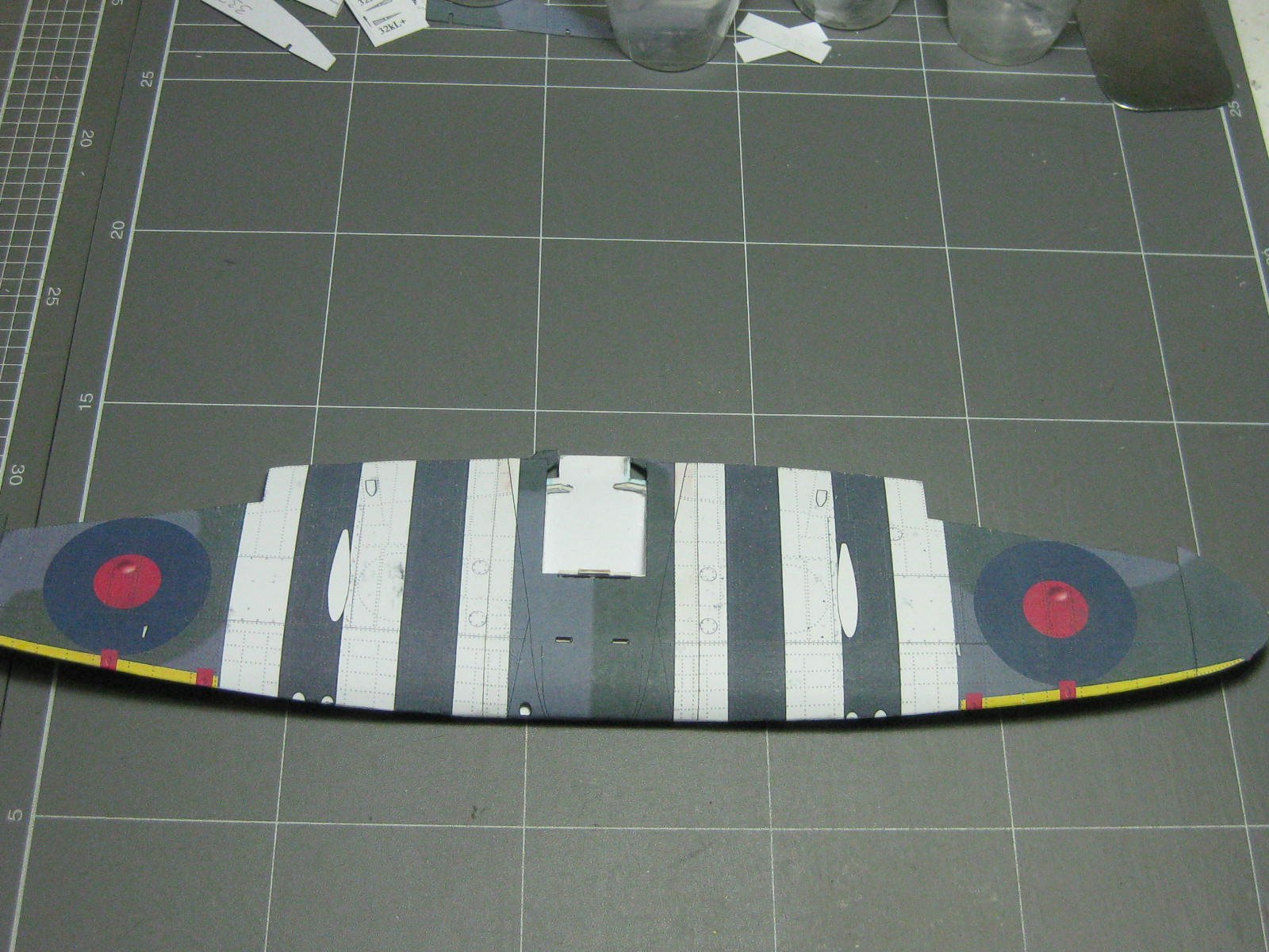
I've finished skinning the wings. They turned out very well, even around the wheel wells
:
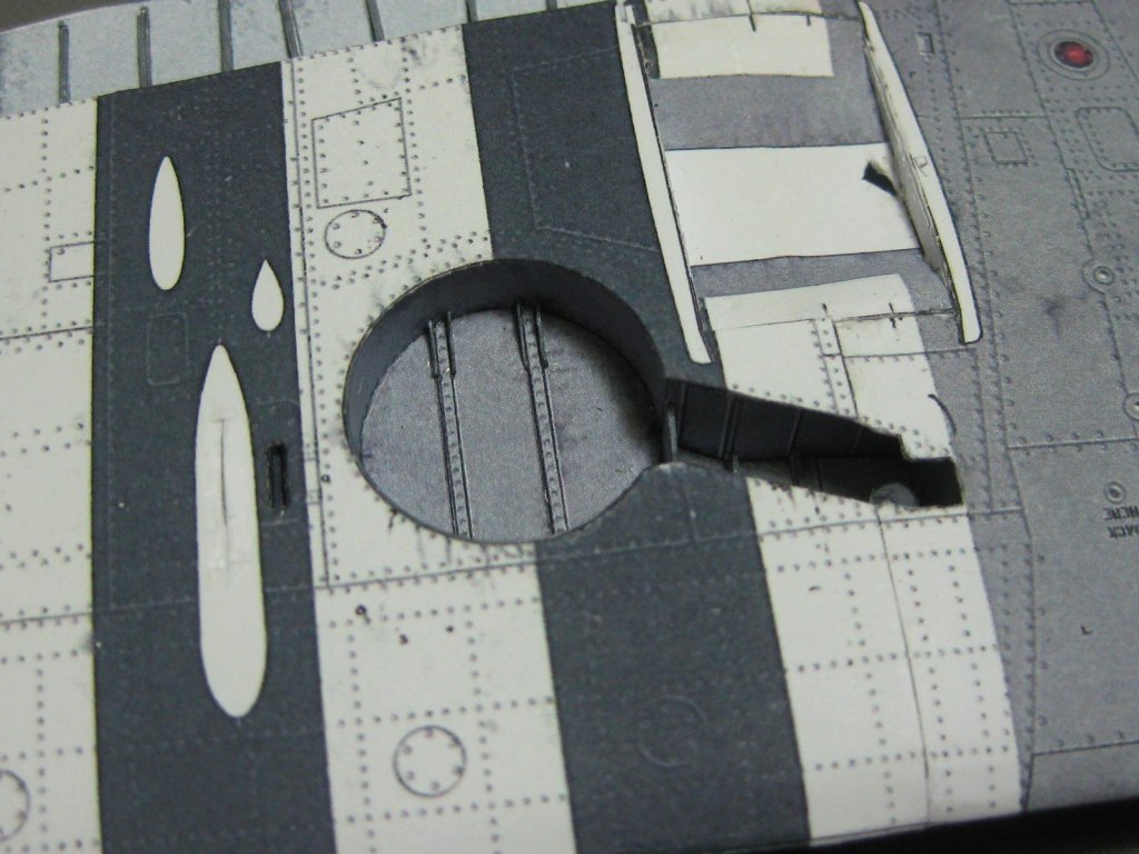
I had to do a little bit of painting on the seams where some white card was showing. I used Acrylic paint mixed up on a palette to get the right shades :
Next I fitted the radiators which I'd made earlier. They were a very tight fit, but after some minor trimming to the framing they fitted very well. After looking at this pic I see I will need to do a bit of minor touching up on a couple of edges :

Danny
-
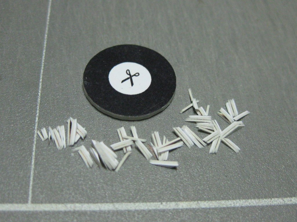
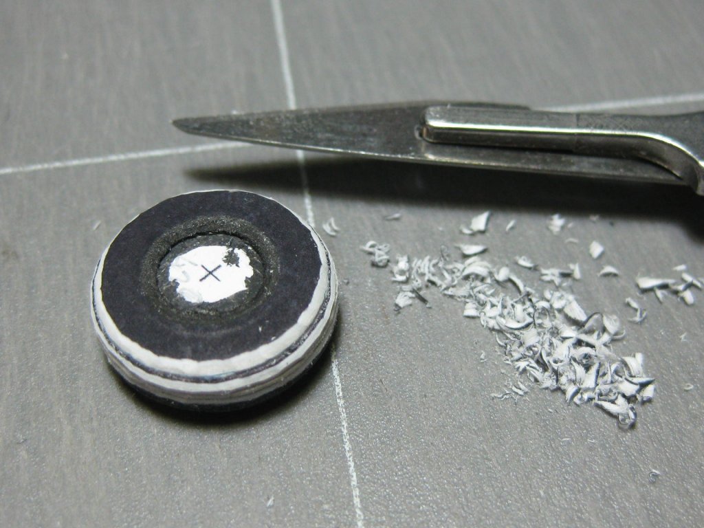
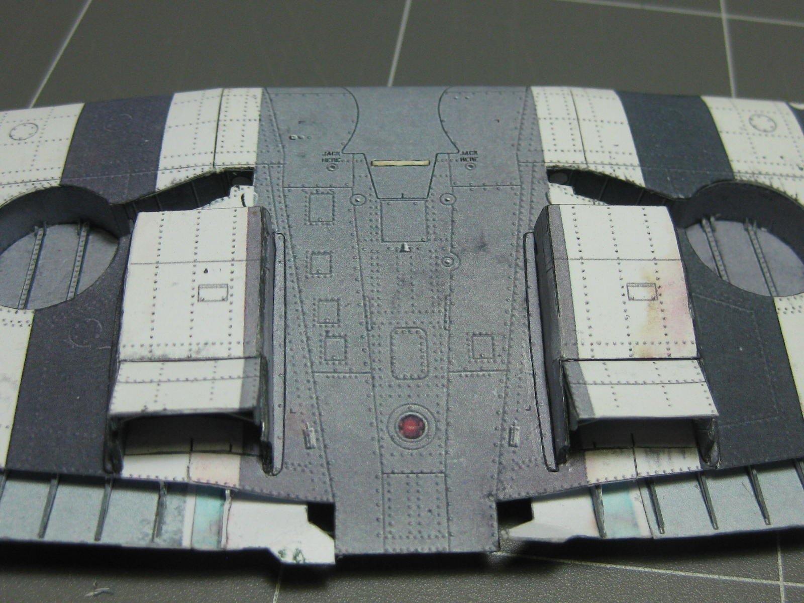
The wheels are laminated together from various diameters of card. Resin wheels are available for this model, but I didn't find that out until after I'd ordered the kit, so I'm going to have a go at making these ones. No real instructions on how to go about the process were with the kit :
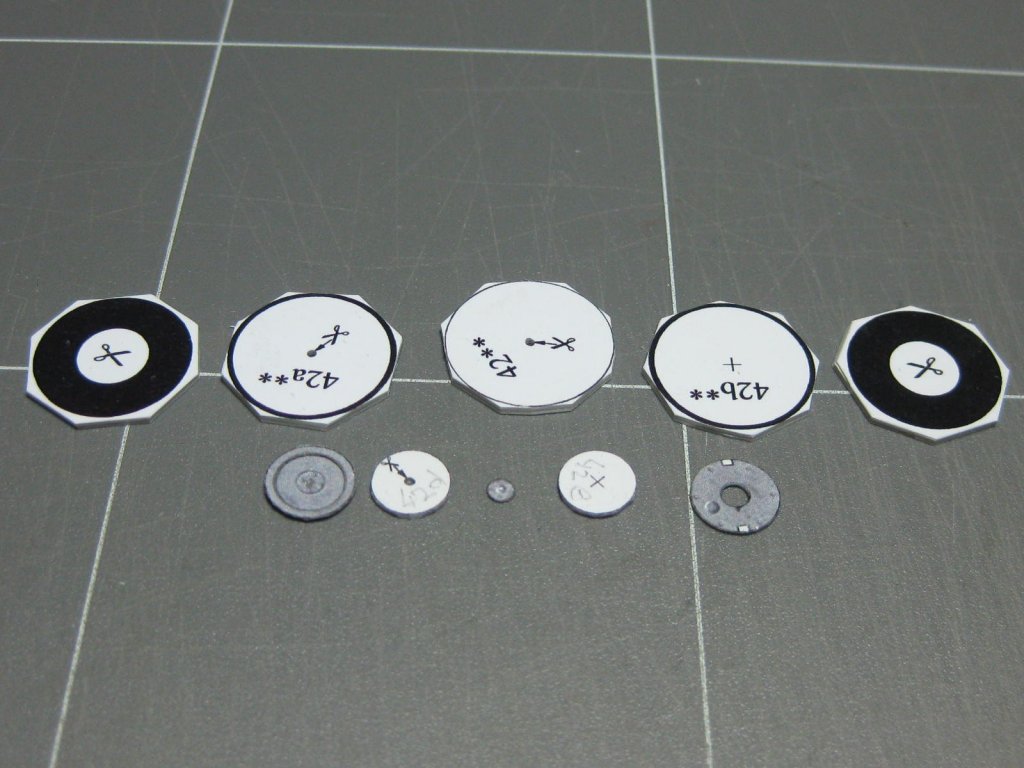
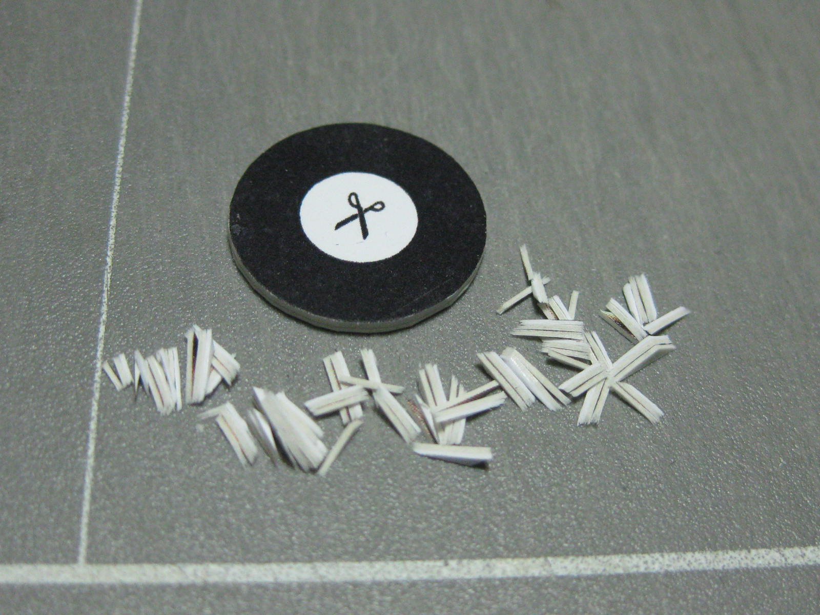
Cutting the outer edge using a scalpel with a chopping motion, one small piece at a time :
The inner edge was cut out using a modified flat blade Xacto chisel. I have 3 of these - 2.0mm, 1.0mm an 0.2mm which are used depending on the radius of the cut. I used the 1.0mm for this part :
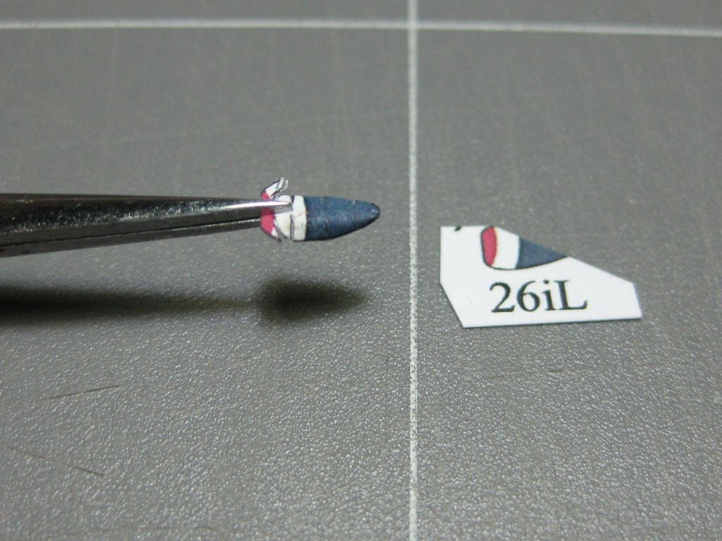
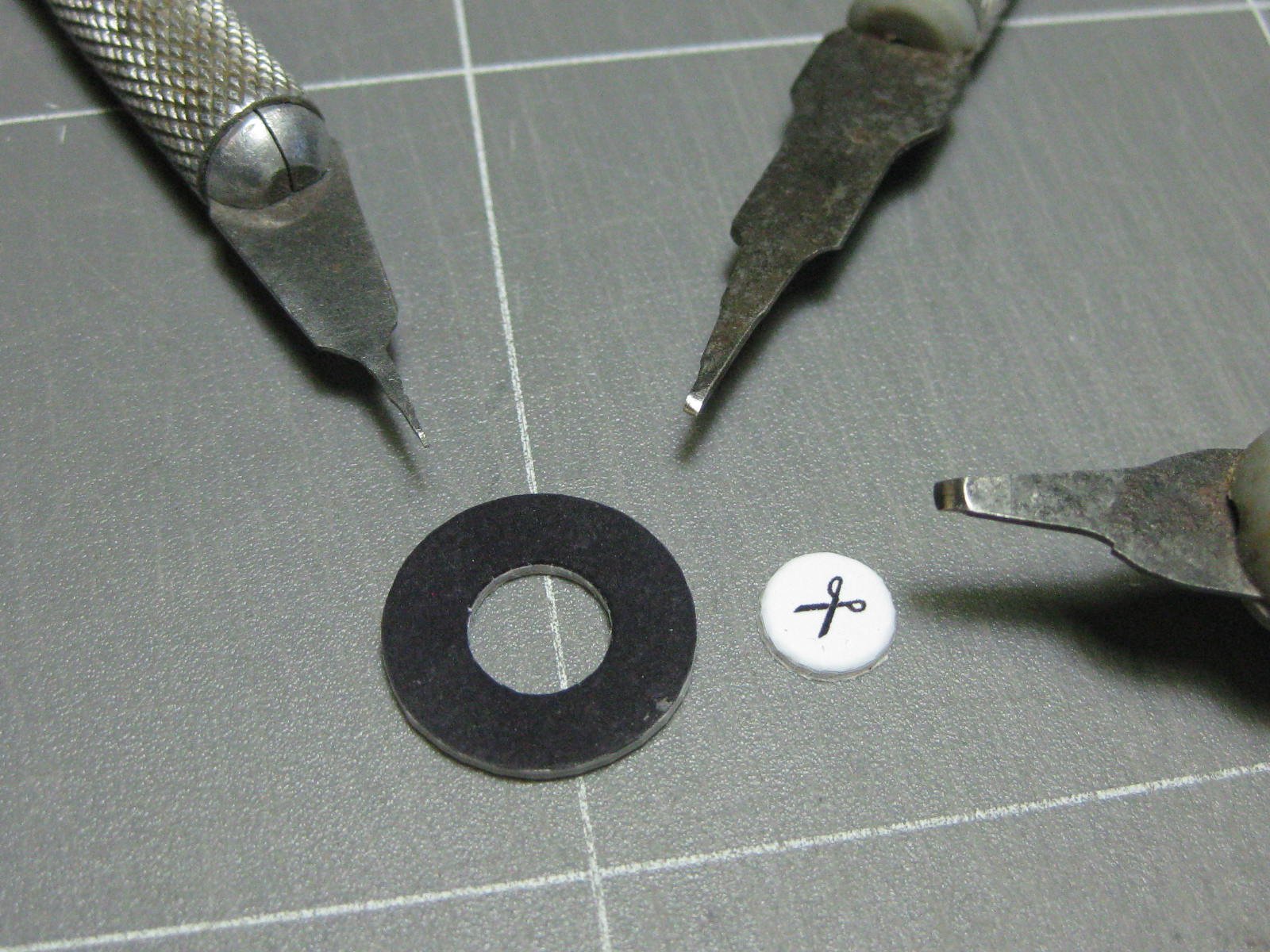
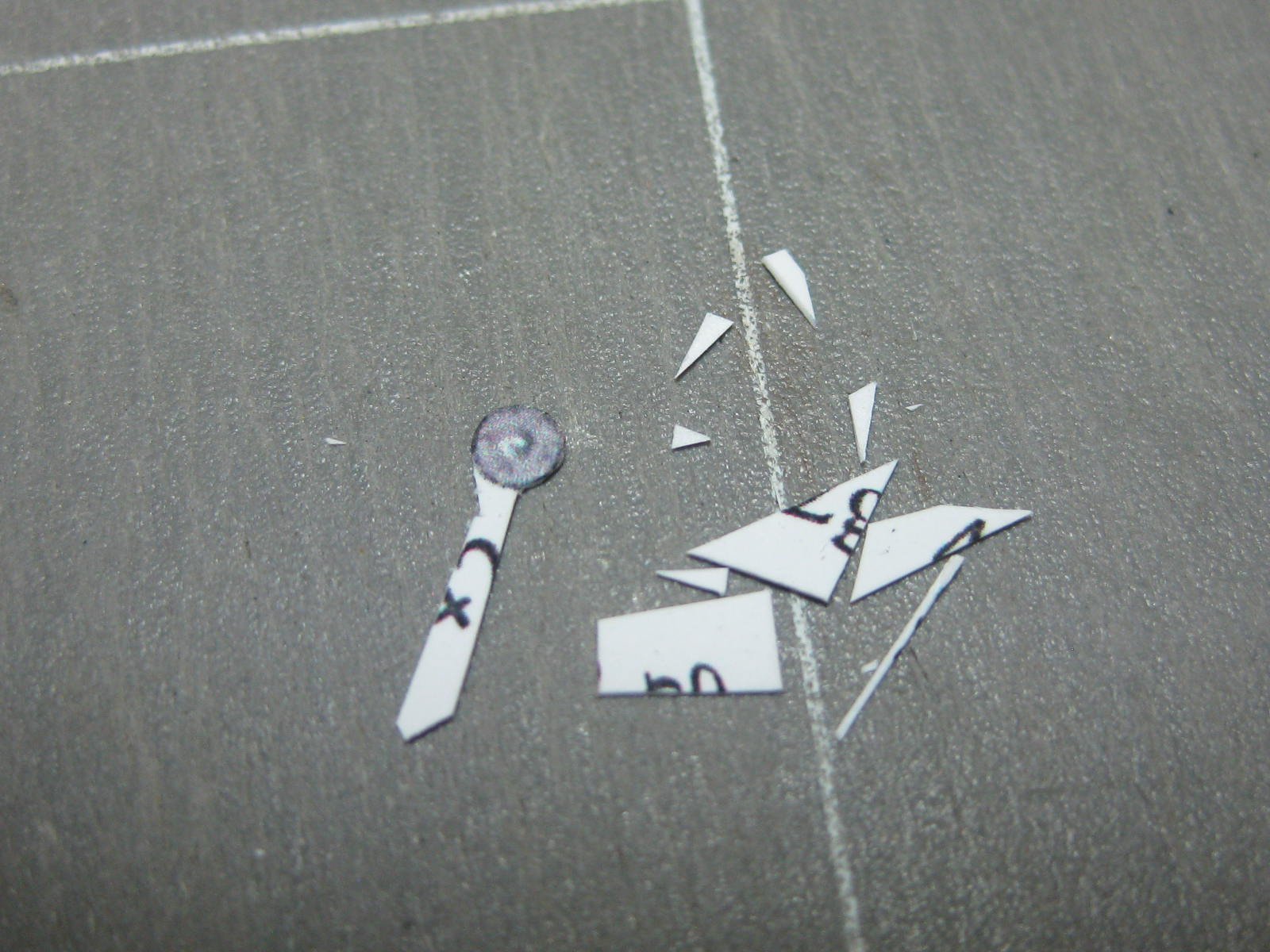
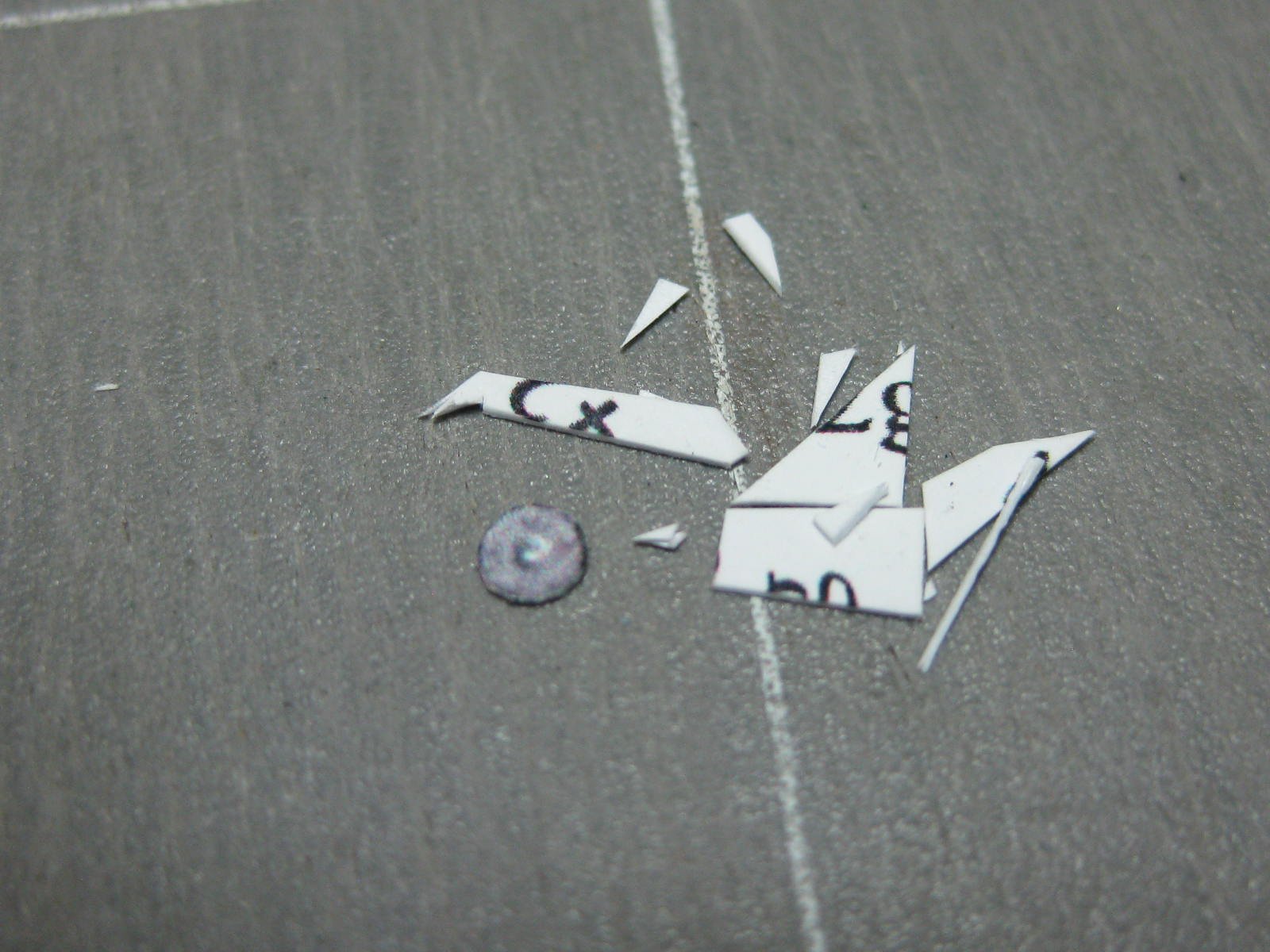
The axle cover is 2.0mm in diameter. I could have simply punched it out of the sheet, but instead I decided to show a bit of a trick on how I handle small parts when cutting them. Note the "handle" I've left to make it easier to hold :
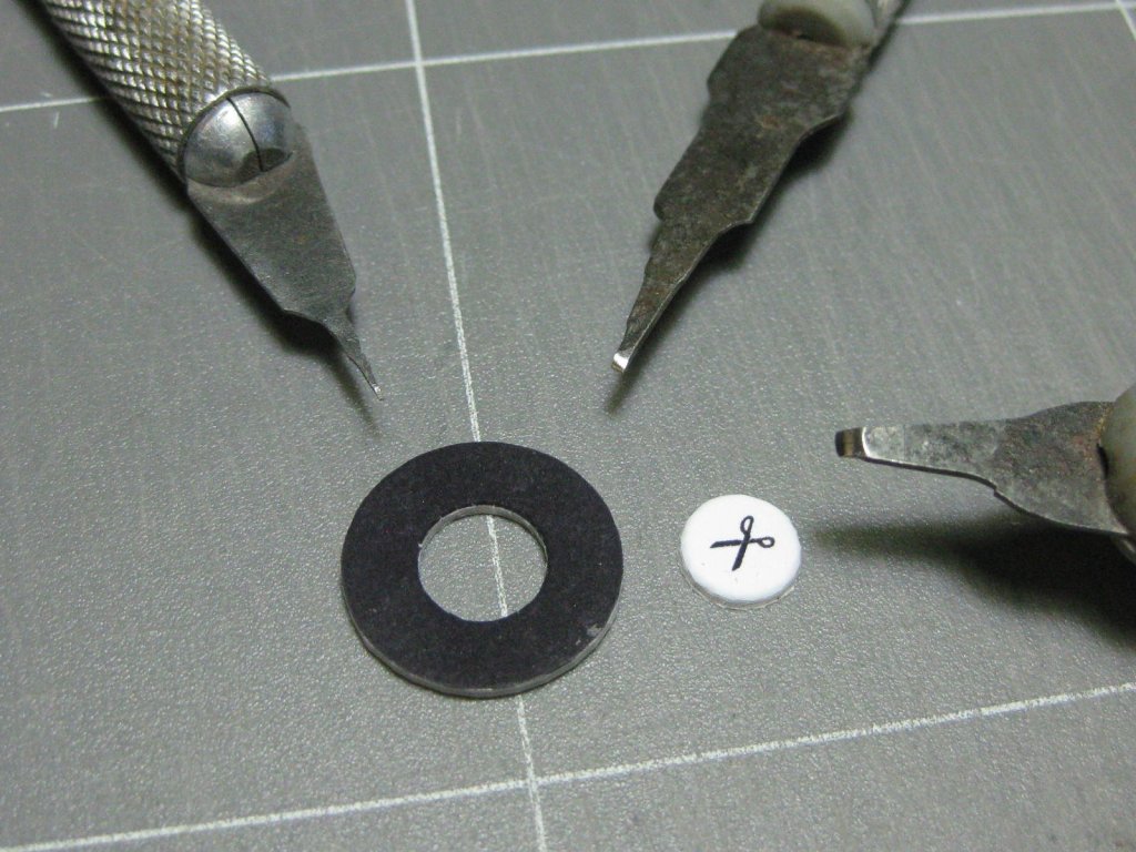
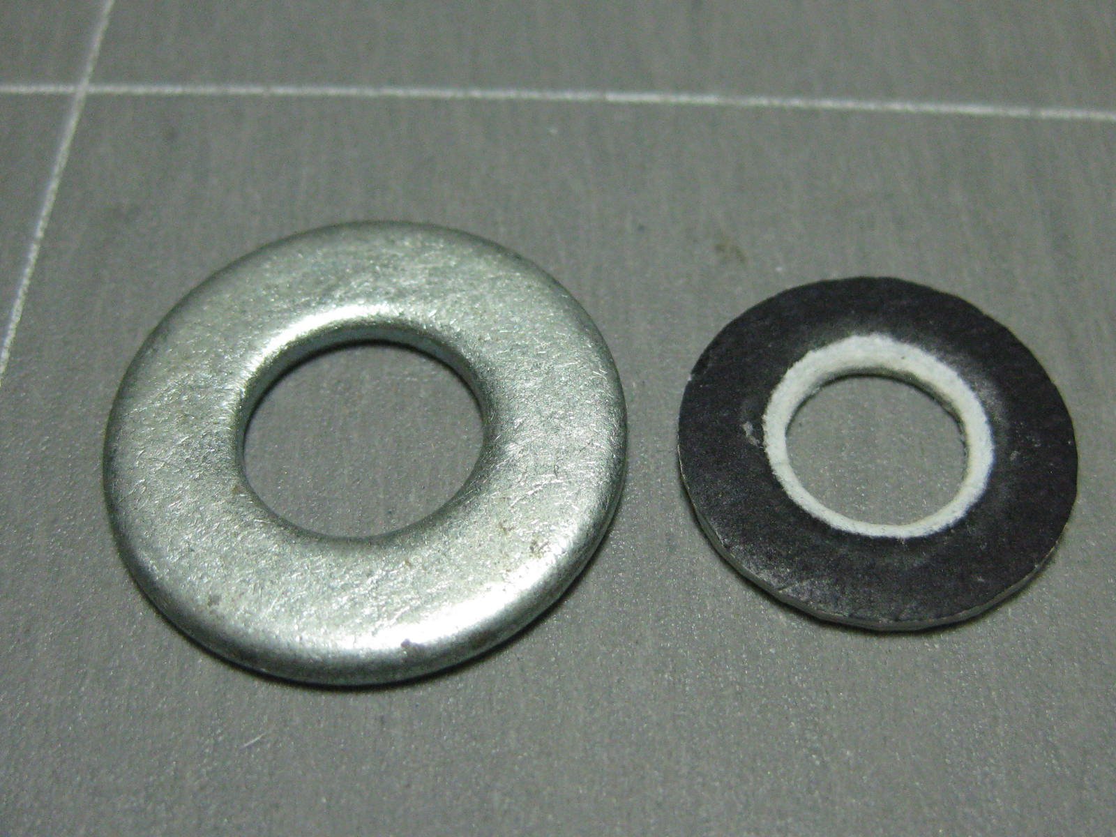
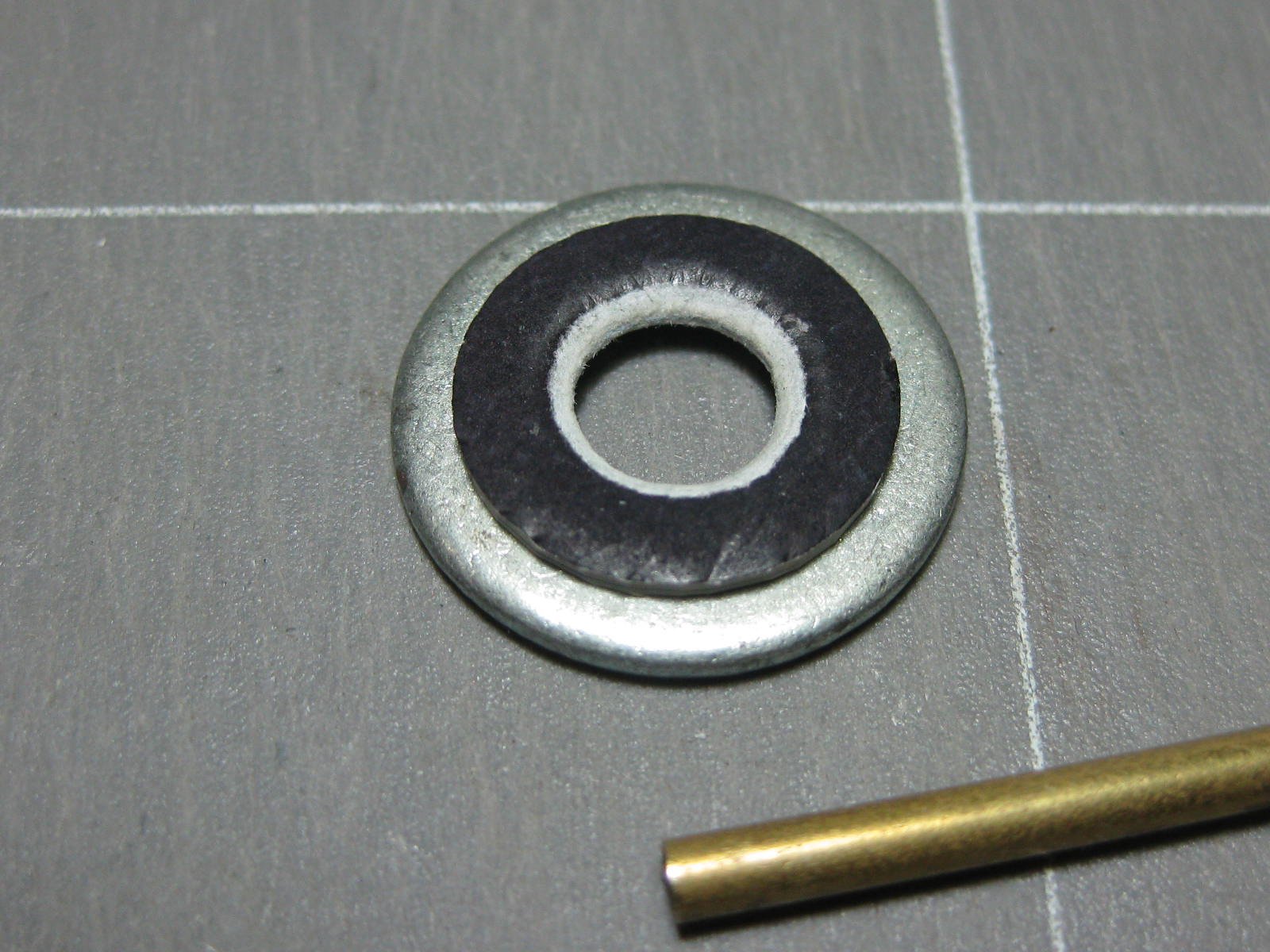
The sidewall has a pronounced curve. I shaped it into the printed part using a 8mm washer which has a rounded inner edge and a piece of 2.5mm brass rod :

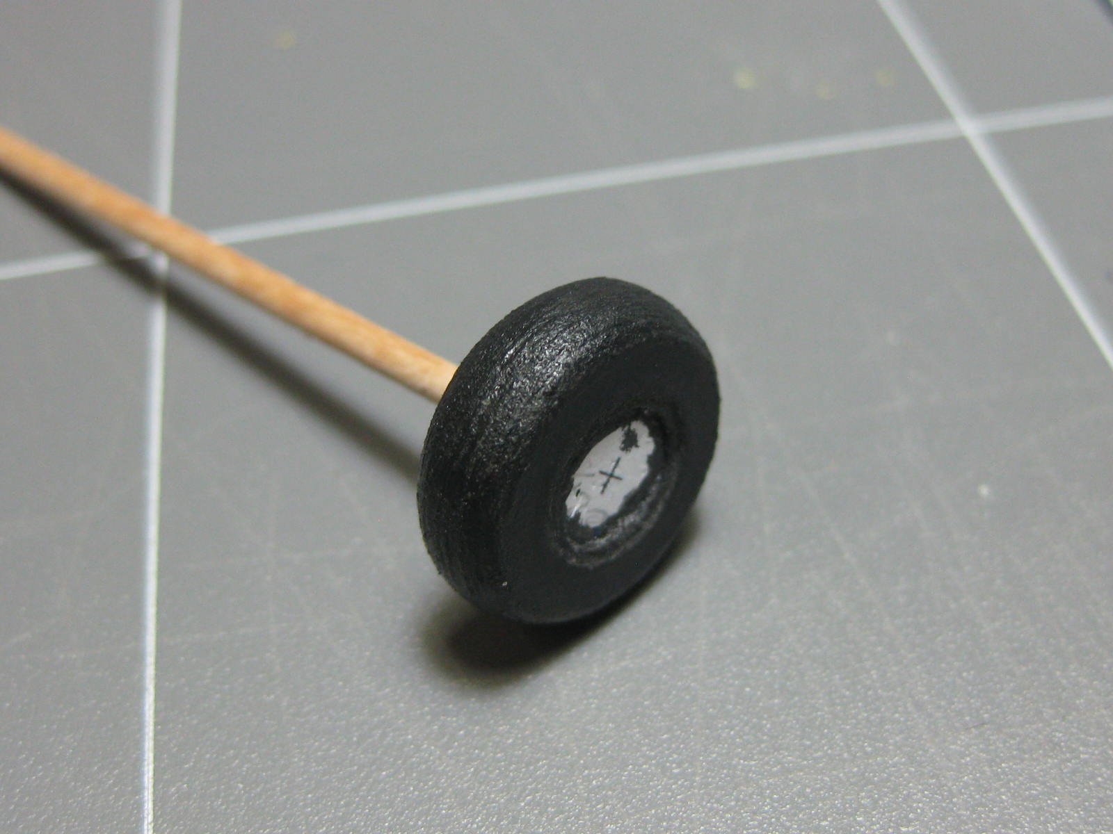
Rounding off the "tread" area starts by trimming with a scalpel to get most of the waste off. This is followed by sanding using 150 grit paper on a sanding stick, and finishing with 400 grit :
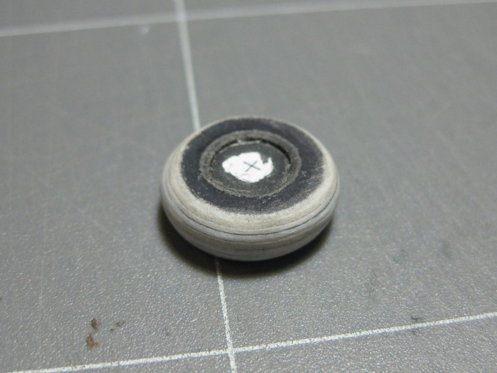
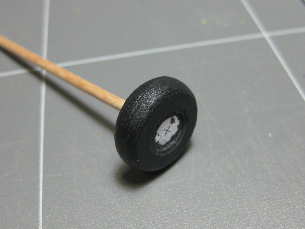
A coat of Sanding Sealer was applied and sanded down again with a 1000-grit flexible pad, then a mix of dark grey acrylic paint finishes the job. This pic was taken just after the paint was applied - the roughness disappeared when the paint dried :
Danny
- thibaultron, lmagna, tkay11 and 7 others
-
10
-
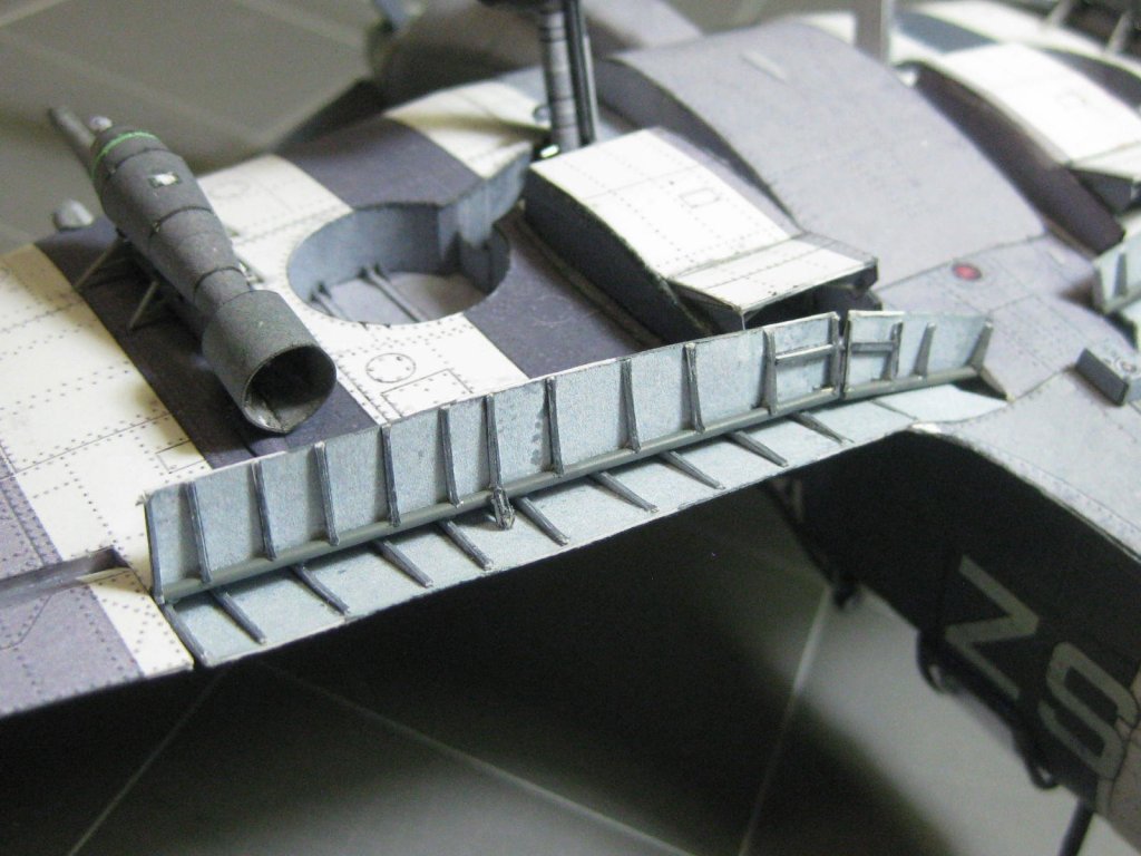
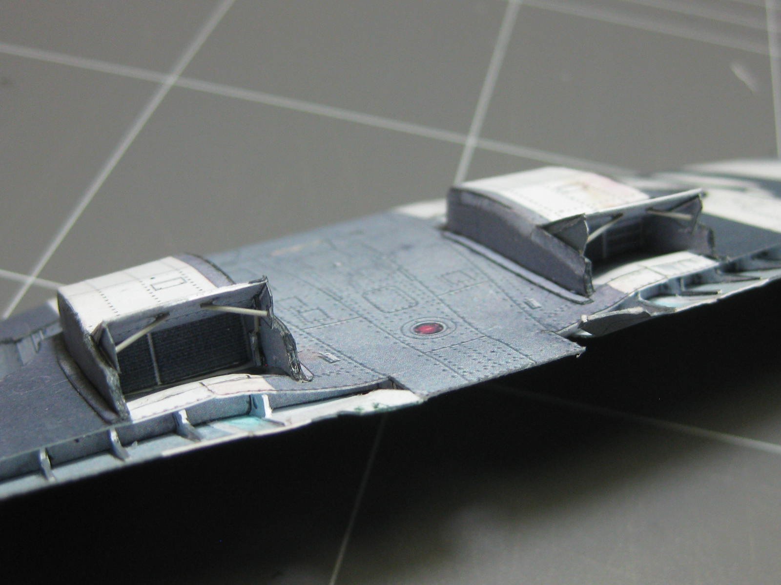
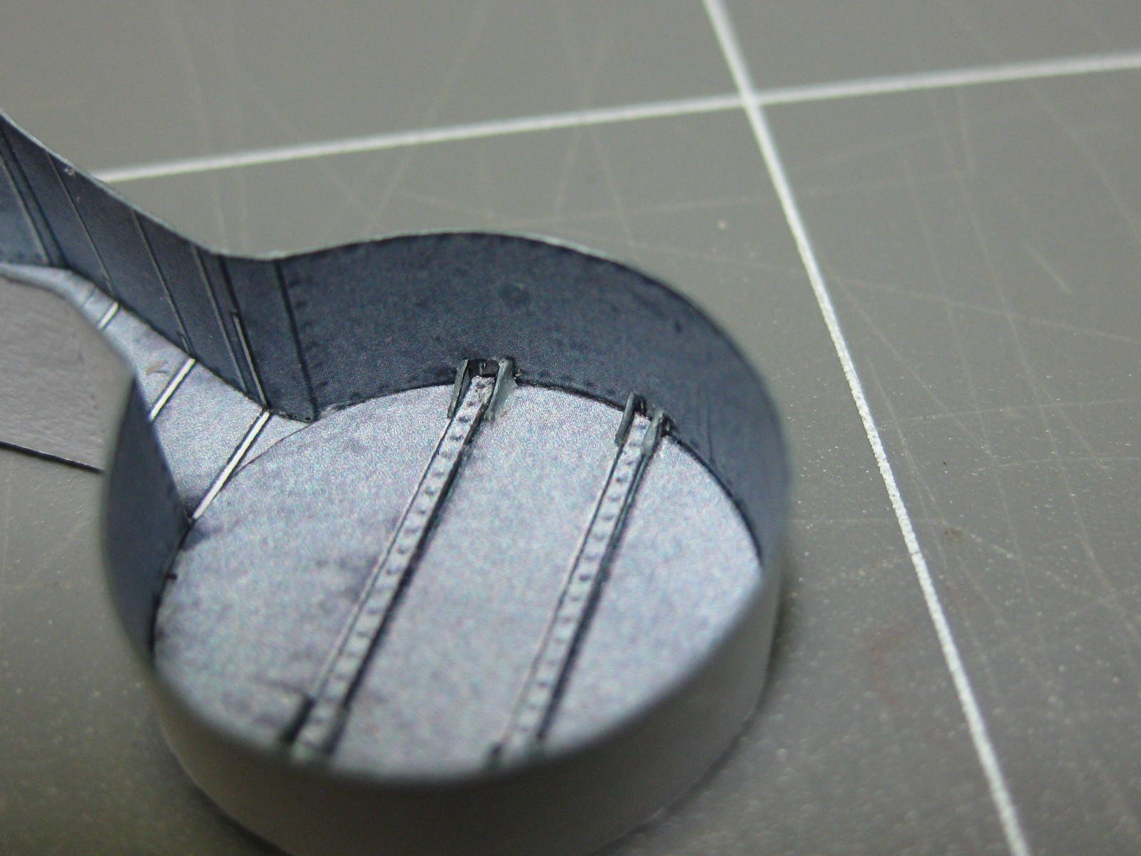
The landing flaps have a lot of bracing ribs attached. This is the half that goes under the wings themselves :
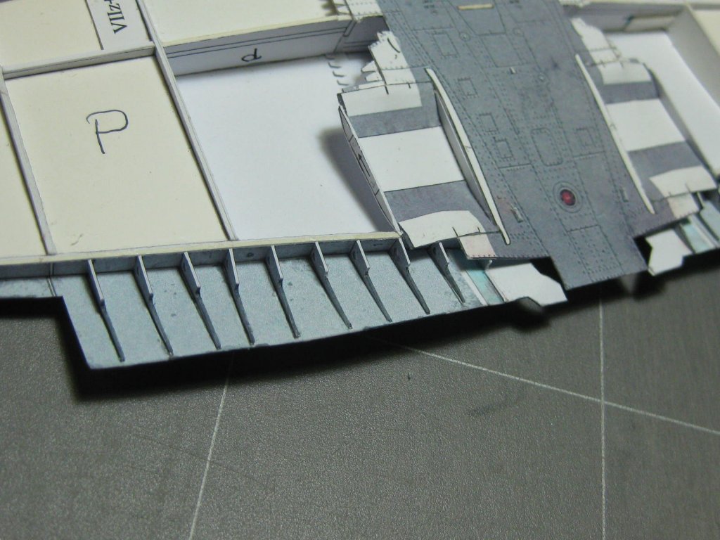
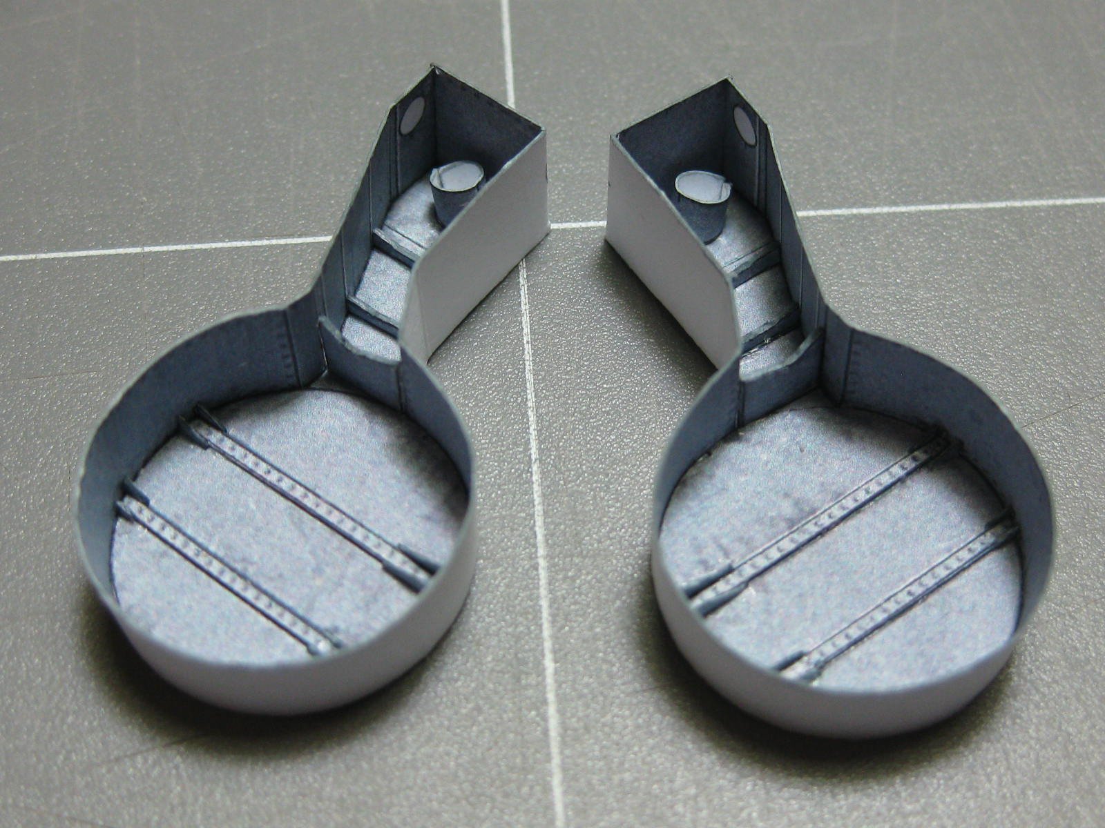
Next step is to make and attach the wheel wells. The smallest parts on this model are the gussets inside them (27j), they took some careful handling :

The wheel wells ready to glue to the wing. This must be done before the lower skin is glued in as there is a bit of trimming to be done to some of the framing - they are a very tight fit :
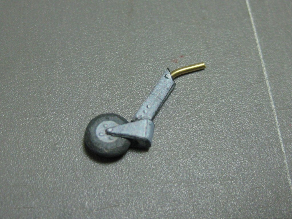
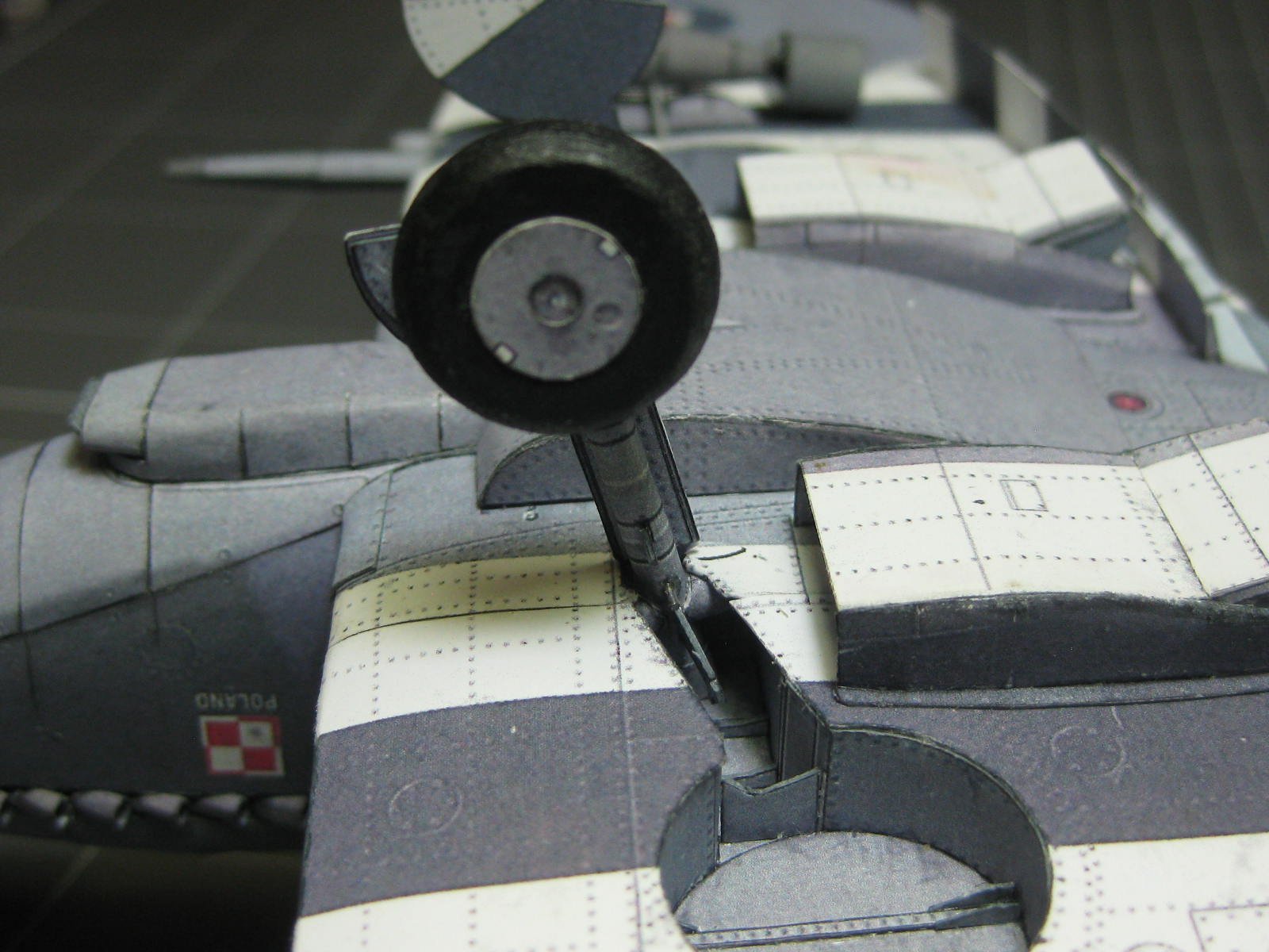
Before gluing the wells in I thought it might be a good idea to make the wheel struts in case there were any problems with fitting them later. They actually fitted perfectly
:
The legs have a number of different diameter steps. A 0.8mm wire in the centre gives added strength to them. The larger wire is for the axle :
Danny
- mtaylor, Canute, GrandpaPhil and 5 others
-
8


Rolls Royce Merlin Engine for Spitfire by Dan Vadas - FINISHED - Alin Osarik design - 1/33 scale - Card
in Non-ship/categorised builds
Posted
Yeah. Fun though .
.
I guess it must be .
.
Danny