Antyronnen
-
Posts
23 -
Joined
-
Last visited
-
 Knocklouder reacted to a post in a topic:
Skuldelev Wreck 3 (Viking knarr) by Antyronnen - Billing Boats - 1:20
Knocklouder reacted to a post in a topic:
Skuldelev Wreck 3 (Viking knarr) by Antyronnen - Billing Boats - 1:20
-
GrandpaPhil reacted to a post in a topic:
Skuldelev Wreck 3 (Viking knarr) by Antyronnen - Billing Boats - 1:20
-
EricWilliamMarshall reacted to a post in a topic:
Skuldelev Wreck 3 (Viking knarr) by Antyronnen - Billing Boats - 1:20
-
mtaylor reacted to a post in a topic:
Skuldelev Wreck 3 (Viking knarr) by Antyronnen - Billing Boats - 1:20
-
Ekis reacted to a post in a topic:
Skuldelev Wreck 3 (Viking knarr) by Antyronnen - Billing Boats - 1:20
-
Cathead reacted to a post in a topic:
Skuldelev Wreck 3 (Viking knarr) by Antyronnen - Billing Boats - 1:20
-
Ian_Grant reacted to a post in a topic:
Skuldelev Wreck 3 (Viking knarr) by Antyronnen - Billing Boats - 1:20
-
ccoyle reacted to a post in a topic:
Skuldelev Wreck 3 (Viking knarr) by Antyronnen - Billing Boats - 1:20
-
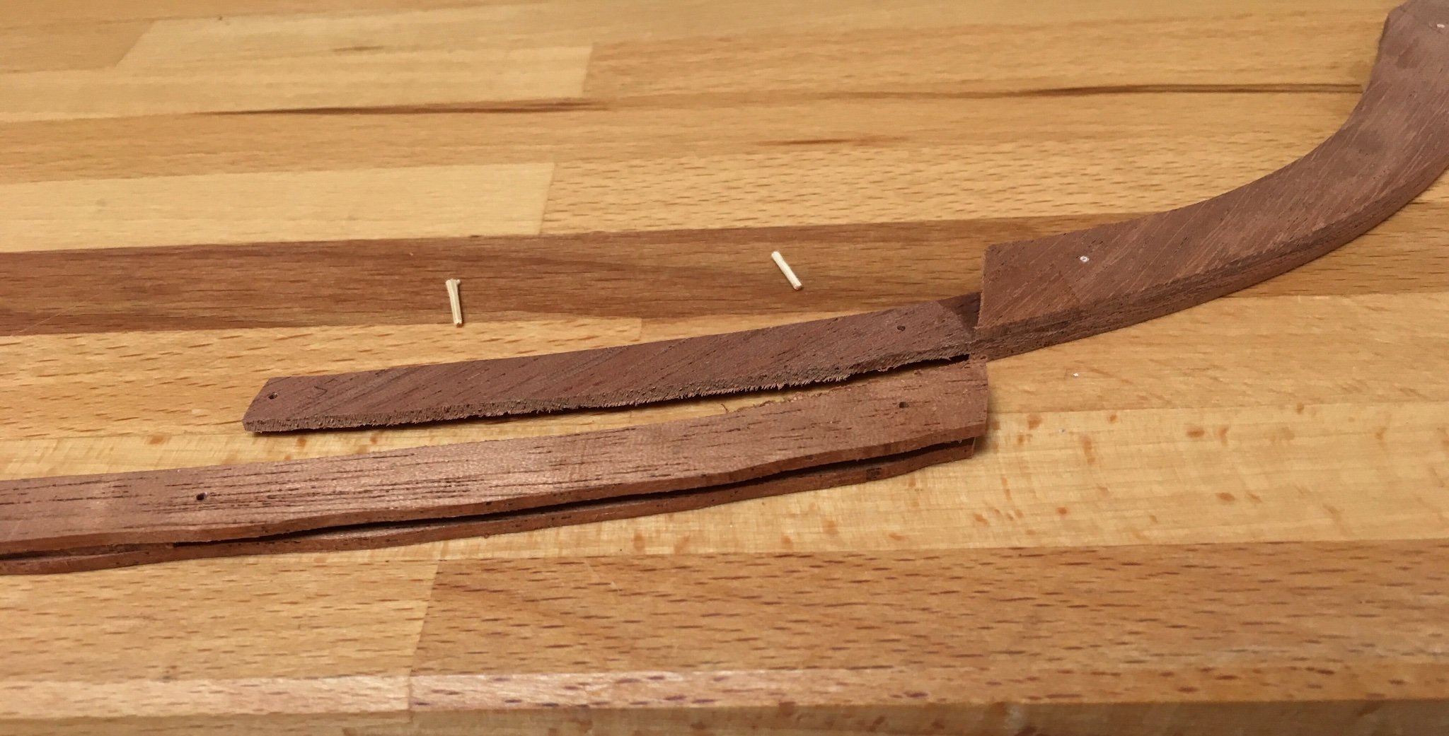
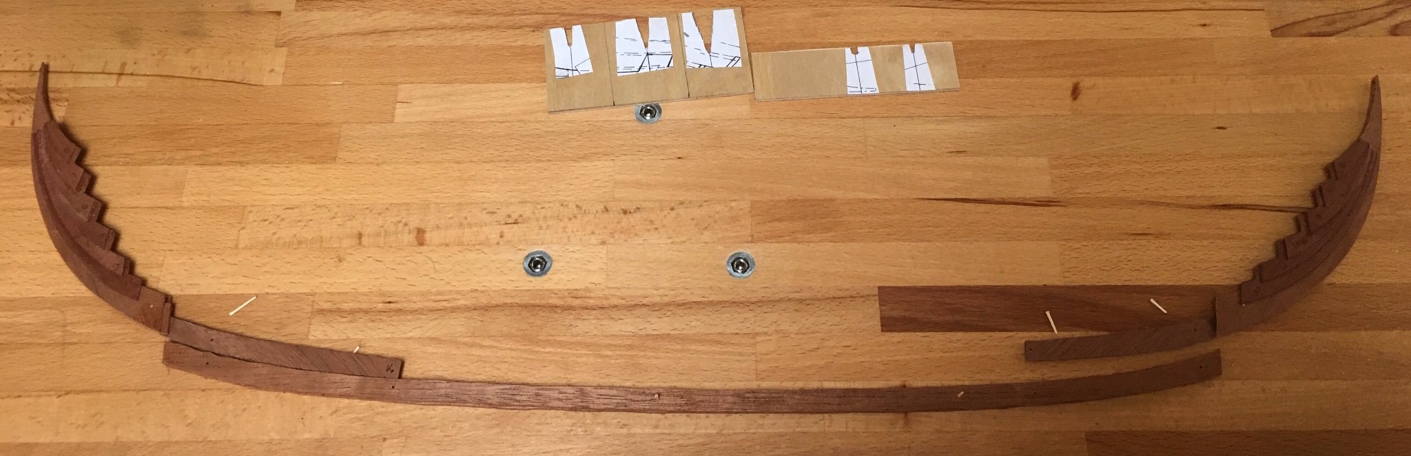
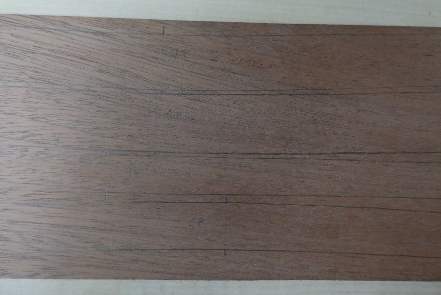
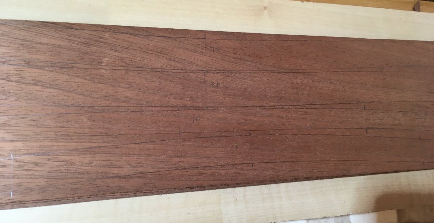
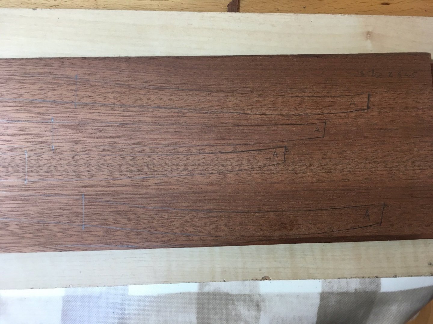
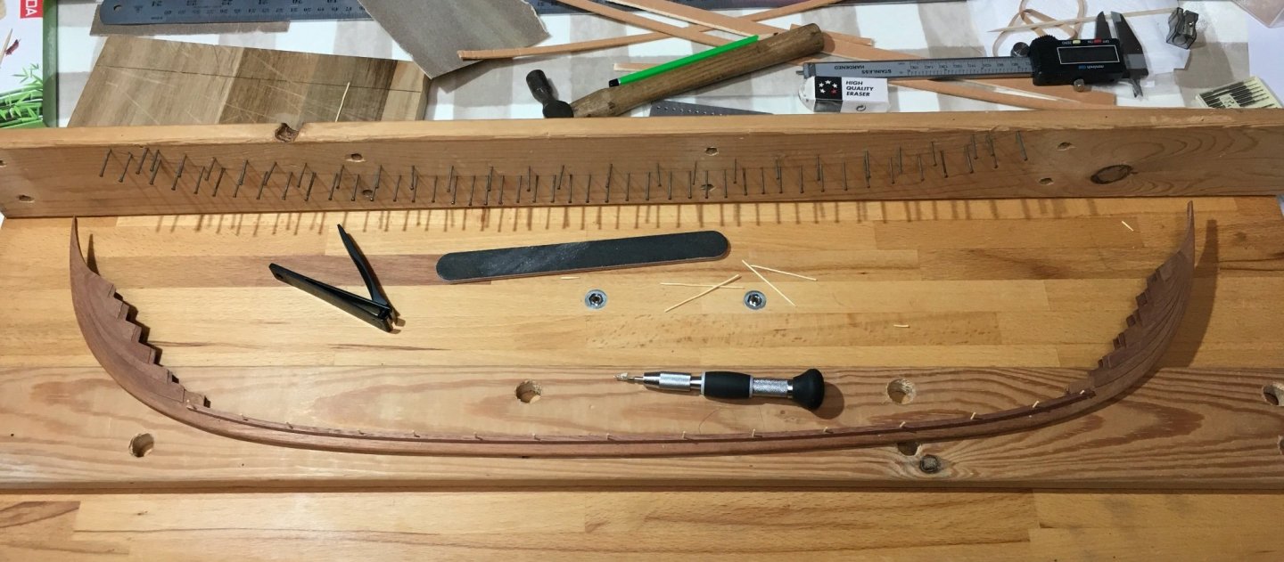
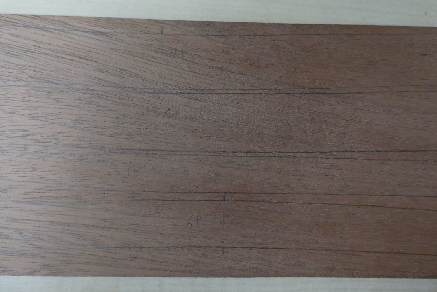
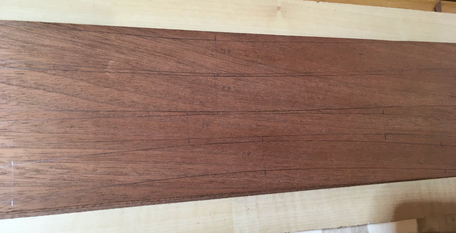
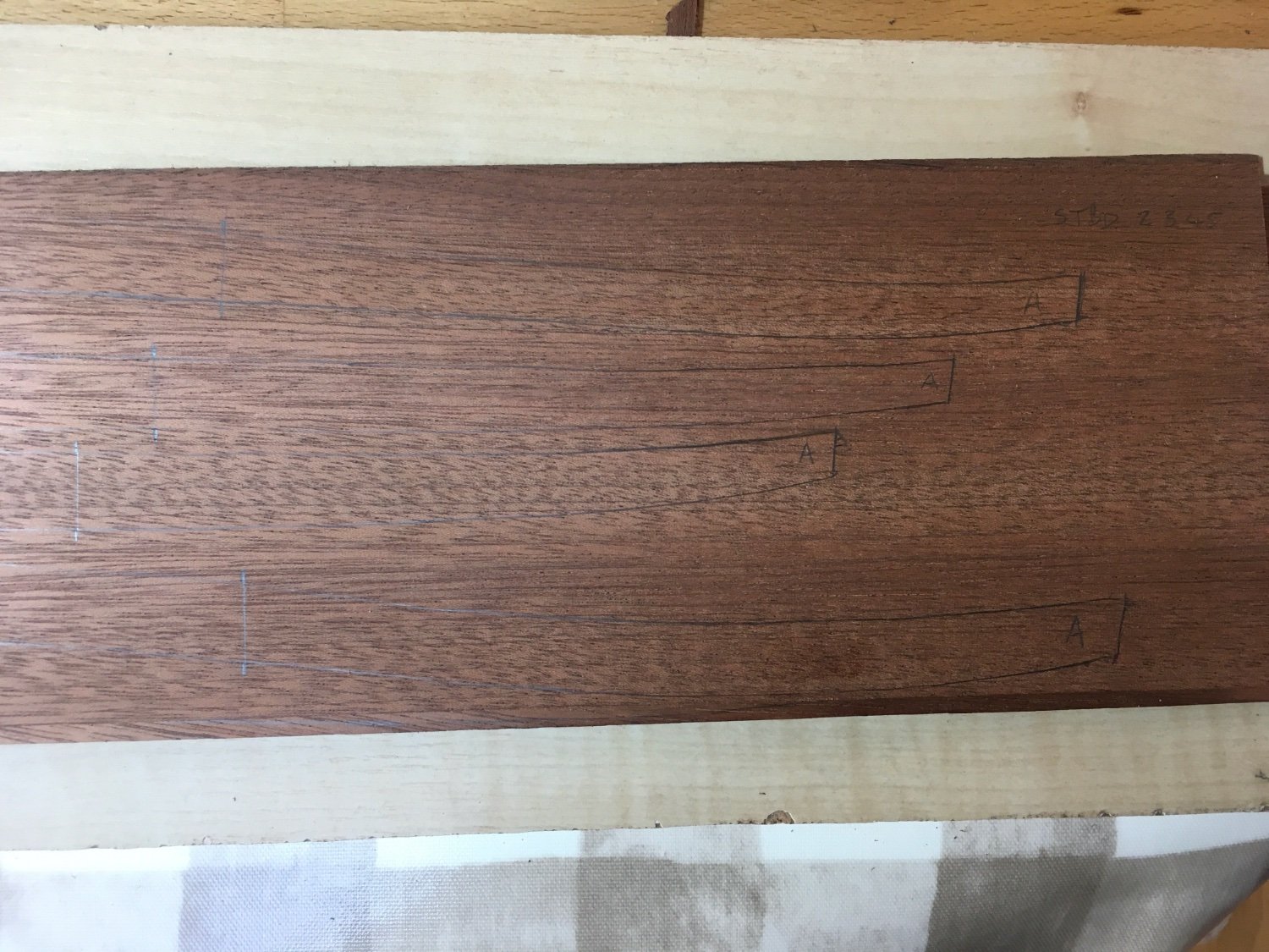
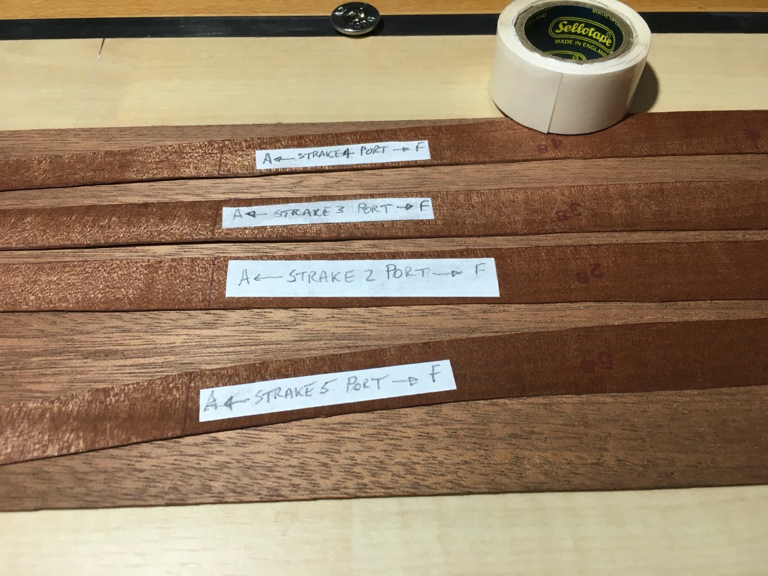
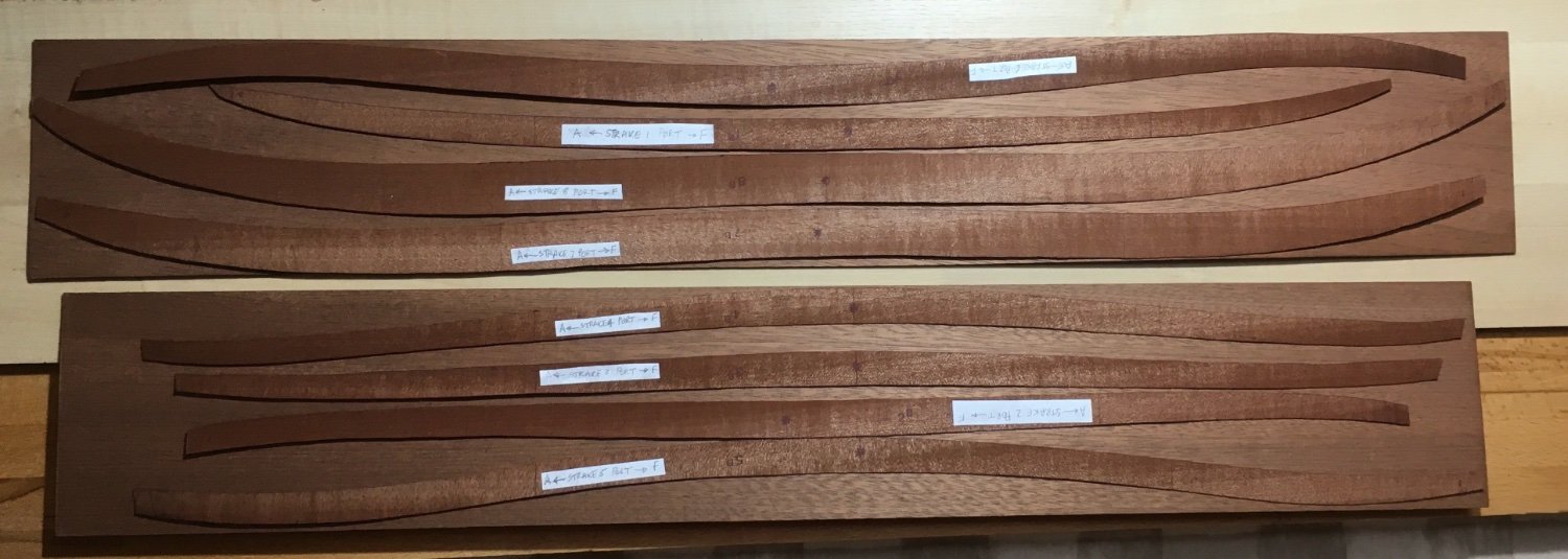
A multitude of reasons for the long gap between posts and now lambing is in full swing so this is a brief catch-up and there may well be a further longish gap until that is over. Having procrastinated with the diversion into rivet options I returned to the main task of deciding how to address the conversion of the planking from the kit-supplied 1mm sheet to my preferred 1.5mm. I experimented with a number of approaches: Photocopying - too much distortion, especially when joining two or more A4 sheets of paper Tracing - the printing on the supplied sheets was insufficiently clear to show through the tracing paper and the traced outlines too error prone (at least in my unsteady hands) over the length of a single strake Template - in the end I opted to cut the strakes from the supplied 1mm sheet and then use them as templates. To reduce the work I used one cut strake as a template for port and starboard labelling each side, as well as fore and aft, as soon as each template was cut out. The cutting was relatively easy since the soaked sheets cut easily with sharp blade. Once all eight templates were cut I could set them out on the thicker sheets to optimise cutting and then drew round them to create four cutting plans, two for port and two for starboard. The templates were fixed to the 1.5mm sheet with double sided Scotch tape which had good ‘hold’ but was relatively easy to separate once the outline had been traced and any residual adhesive was cleaned off with Isopropanol. Once the port strakes were done the templates were removed, turned over, re-fixed, and the process repeated for starboard strakes. Templates laid out for draft cutting sheet, in this case Port. Close up of labelled templates fixed to 1.5mm sheet Having finally decided on the optimum layout for cutting the next stage was to draw round the templates. I used pencil rather than a permanent 'fine writer' on the basis that the pencil markings, although less visible, would be easier to remove . It was quite difficult choosing the softness of pencil to use for tracing round the templates. Using a soft pencil made for more visible lines but they were thicker than I would have liked. In the end a compromise HB was used. With appropriately angled strong lighting I hope the outlines will be easily visible when scroll sawing. The end results are shown below. The problem of visibility is apparent although overemphasised because of the limitations of my camera and lighting setup. I managed to get my scrollsaw out of hibernation and set up yesterday but I suspect it will be a few weeks before I have enough uninterrupted time out of the lambing shed to start cutting out strakes. I will however have plenty of spare wool should I wish to caulk the seams! Antony


-
Rob S reacted to a post in a topic:
For Beginners -- A Cautionary Tale
-
GrandpaPhil reacted to a post in a topic:
Skuldelev Wreck 3 (Viking knarr) by Antyronnen - Billing Boats - 1:20
-
This sounds like a potential solution to splitting in thin wood. 50+ years ago I made a couple of Graupner kits (Oseberg Ship and Santa Maria) and they used masses of thin ply which was strong but inflexible. What adhesive would you use in your ‘ply’ to maintain flexibility? Antony
-
I suspect some of this is really displacement activity to put off starting the business of actually cutting and fitting planks! Now I have decided how to deal with the rivets I’ll just have to get on with building the ship …tomorrow. Antony
-
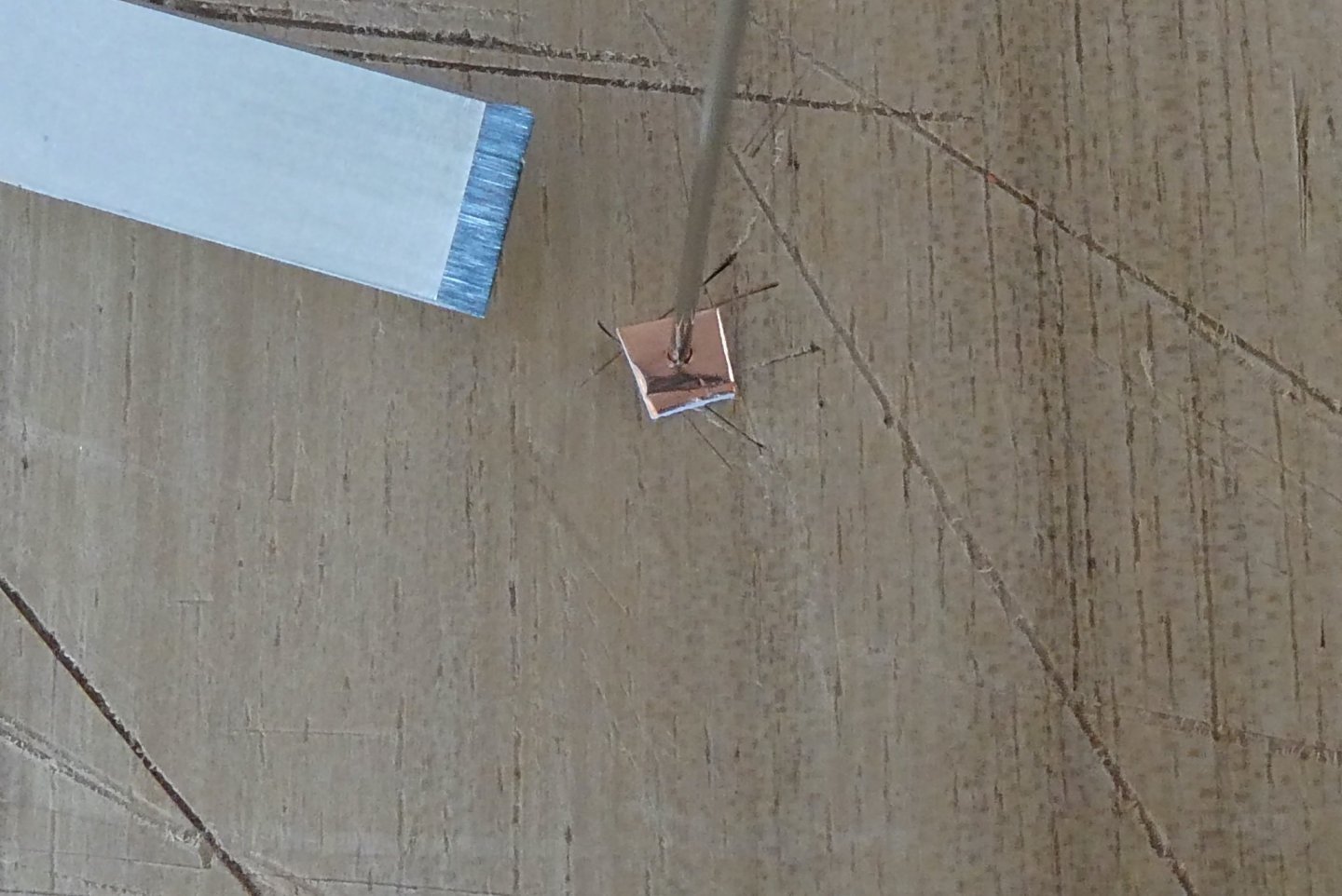
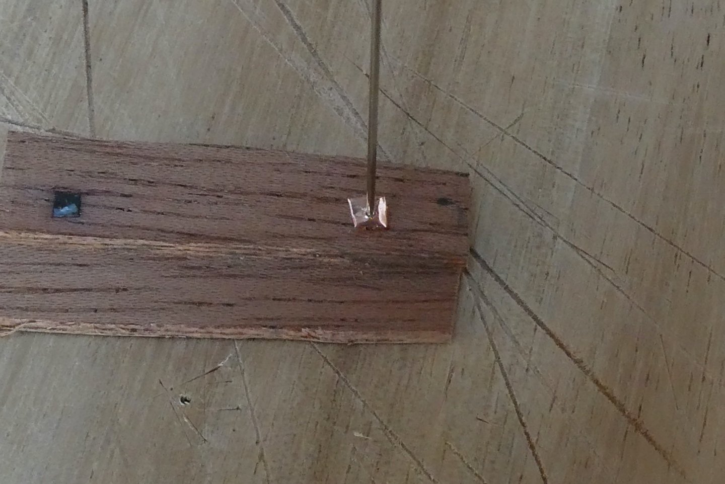
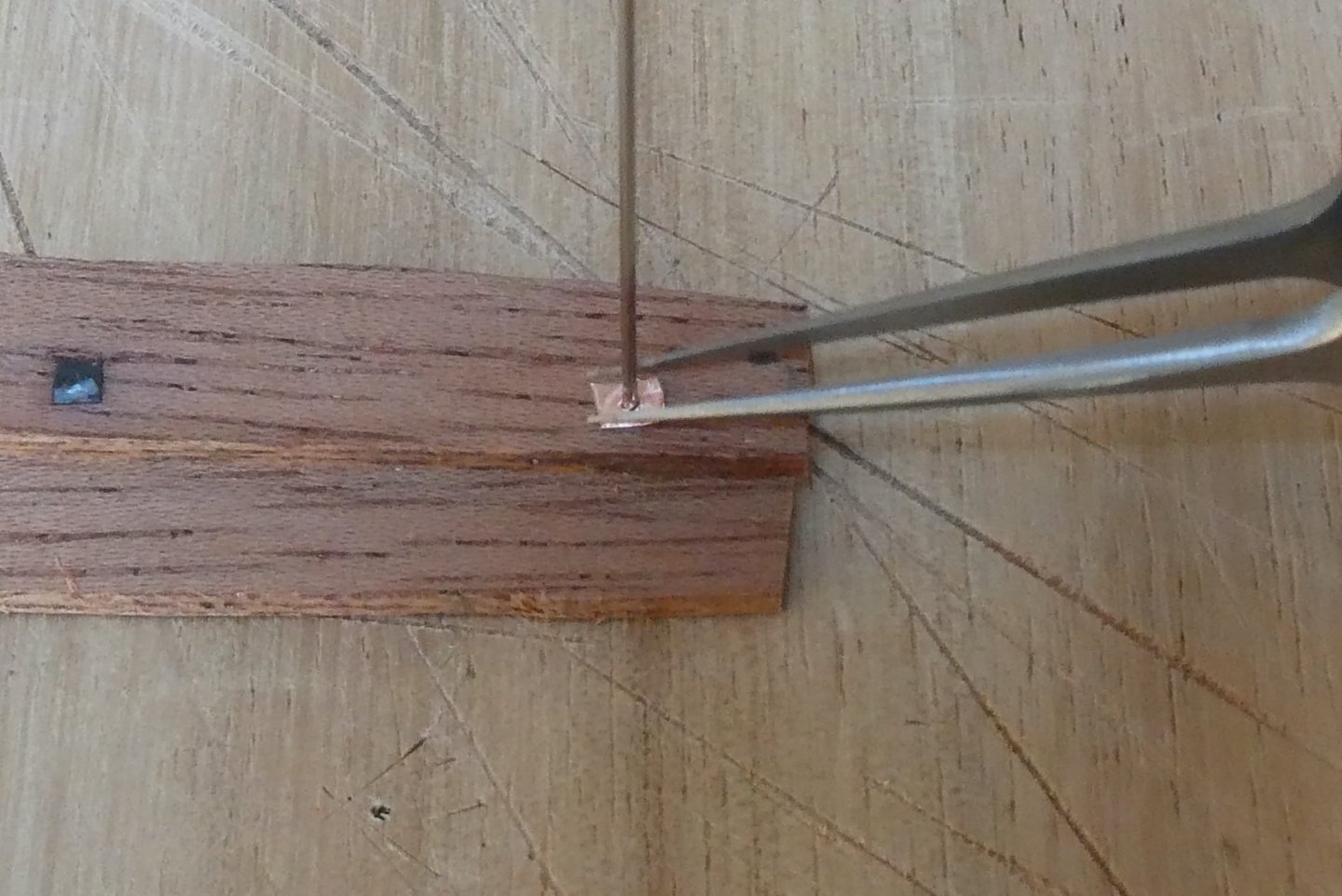
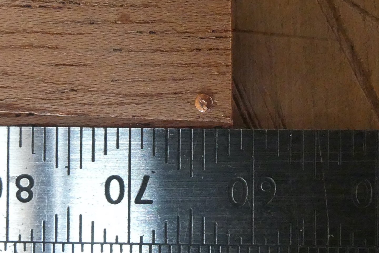
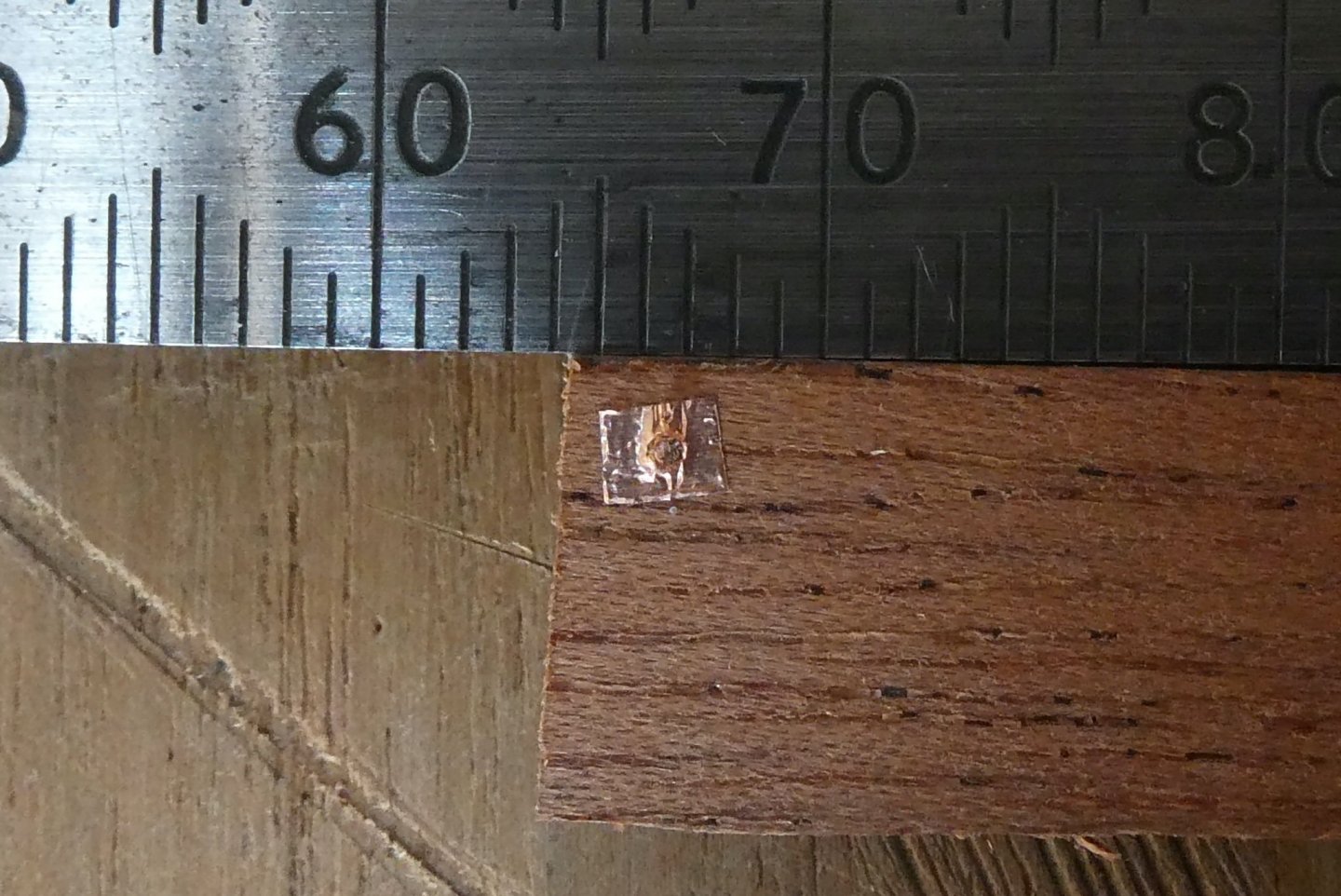
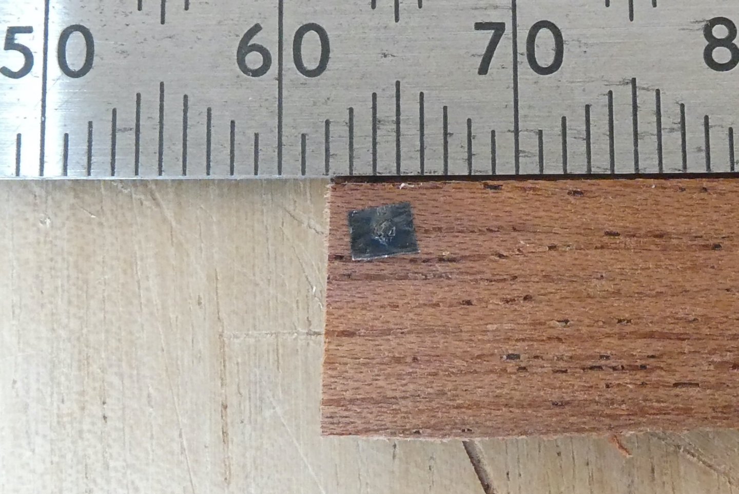
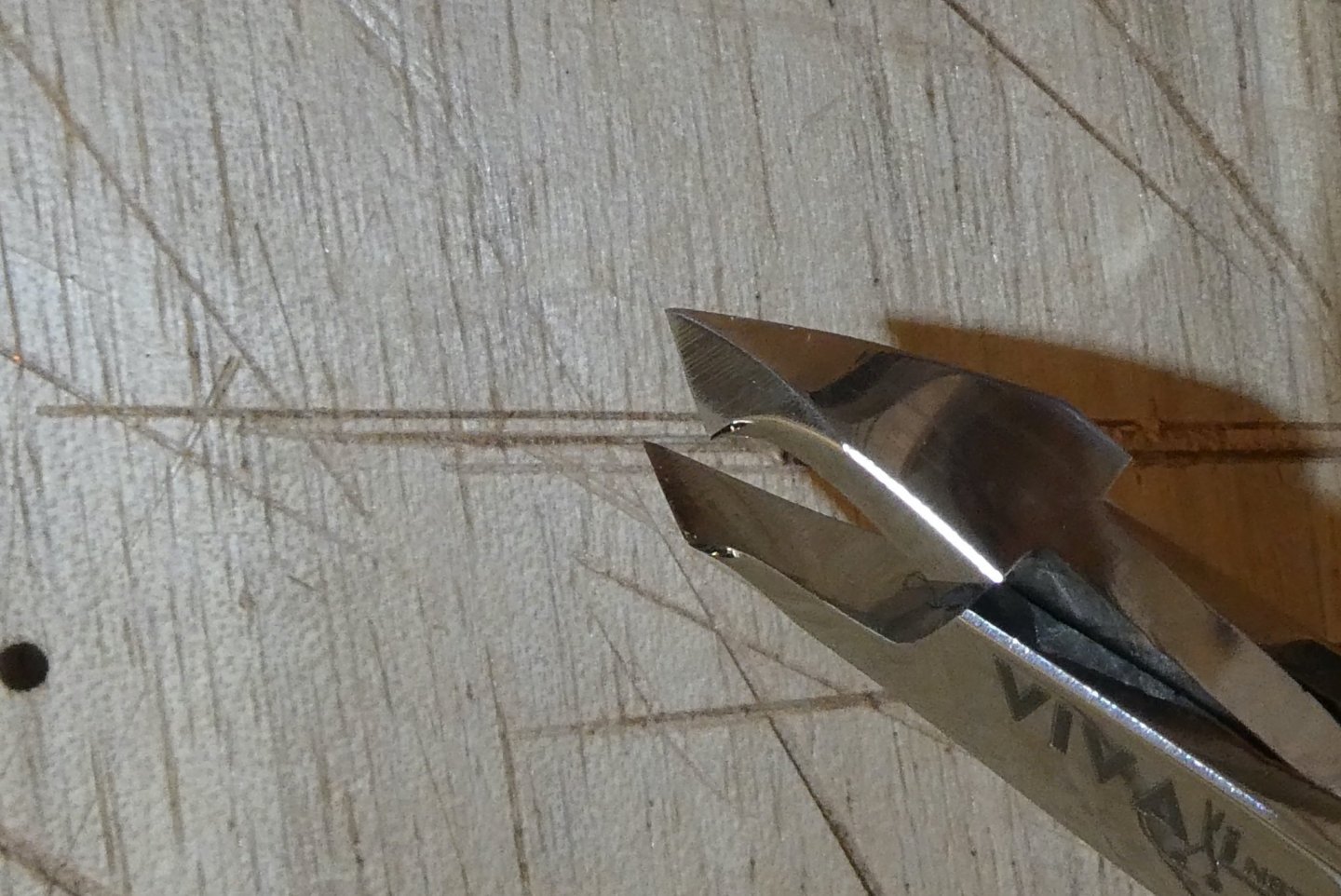
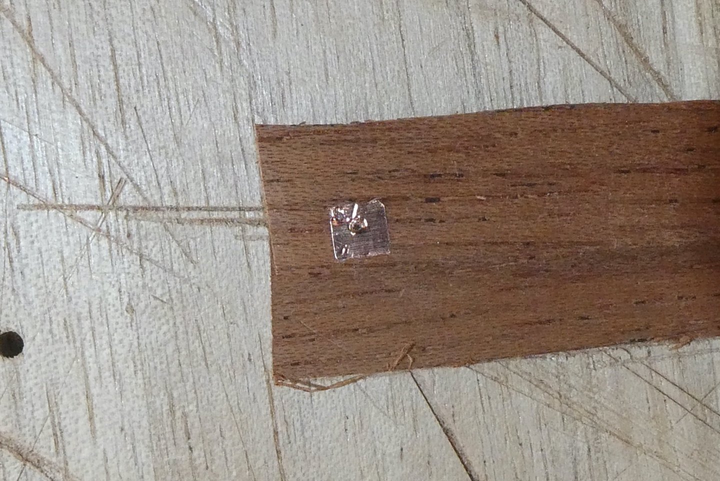
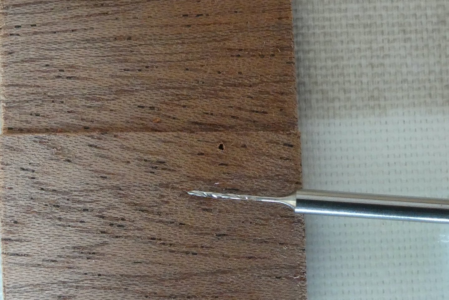
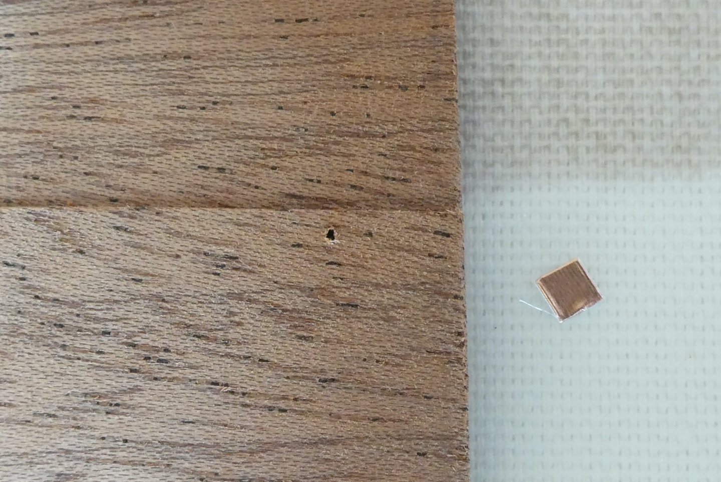
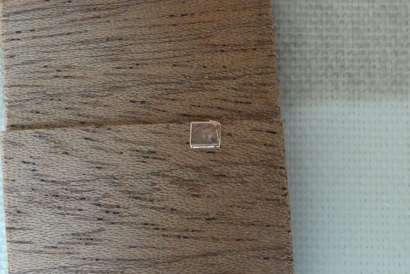
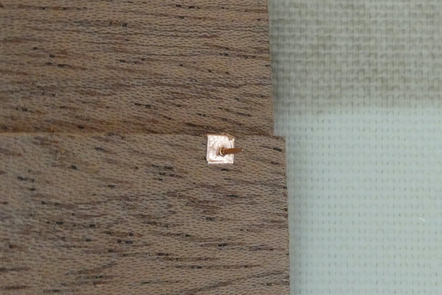
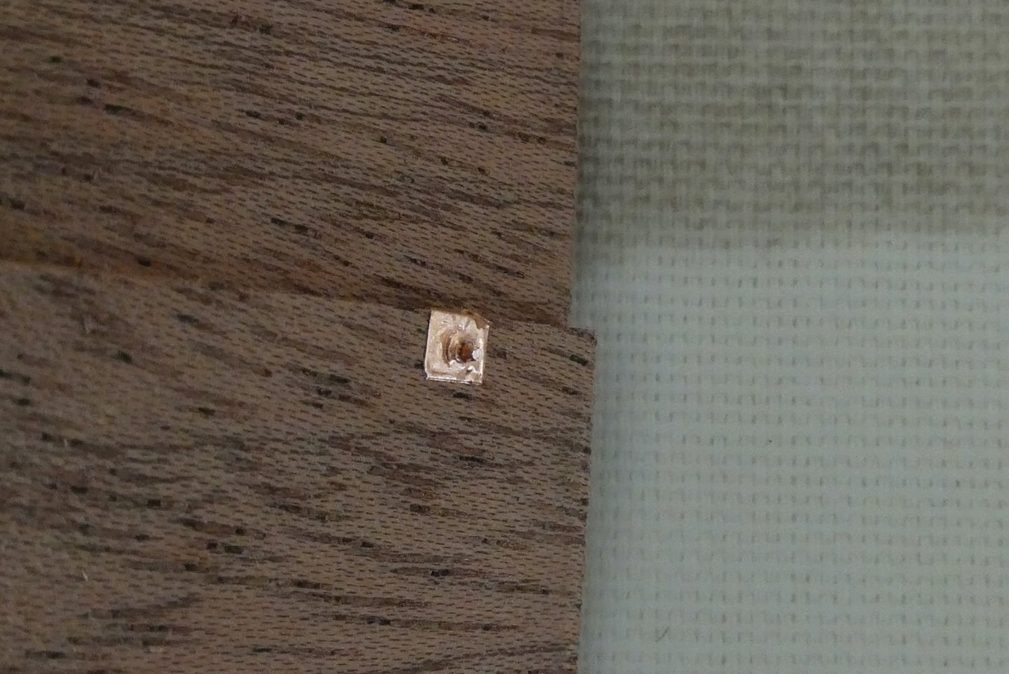
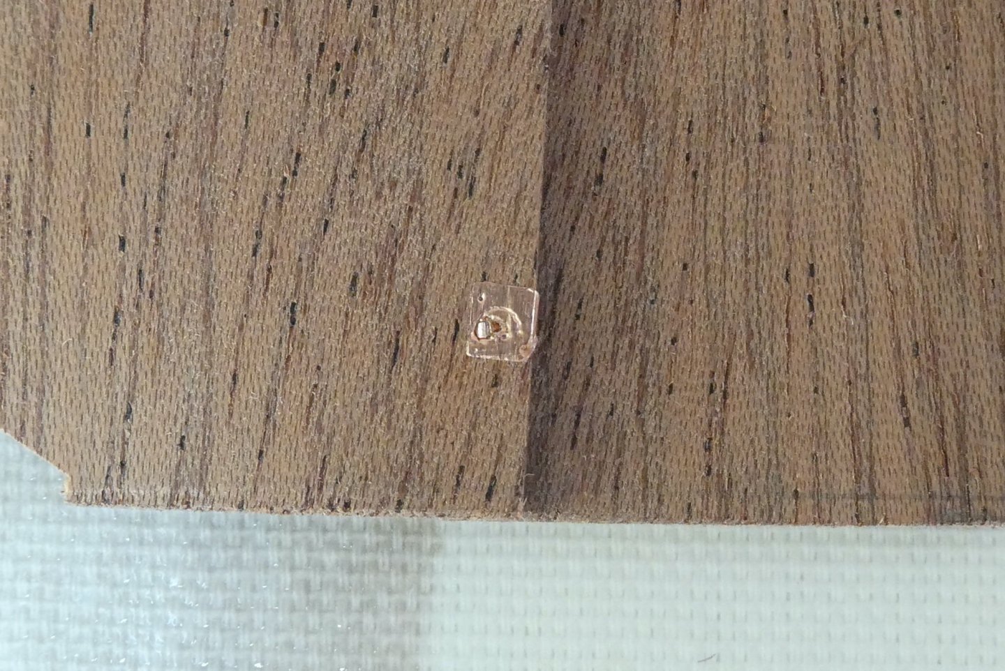
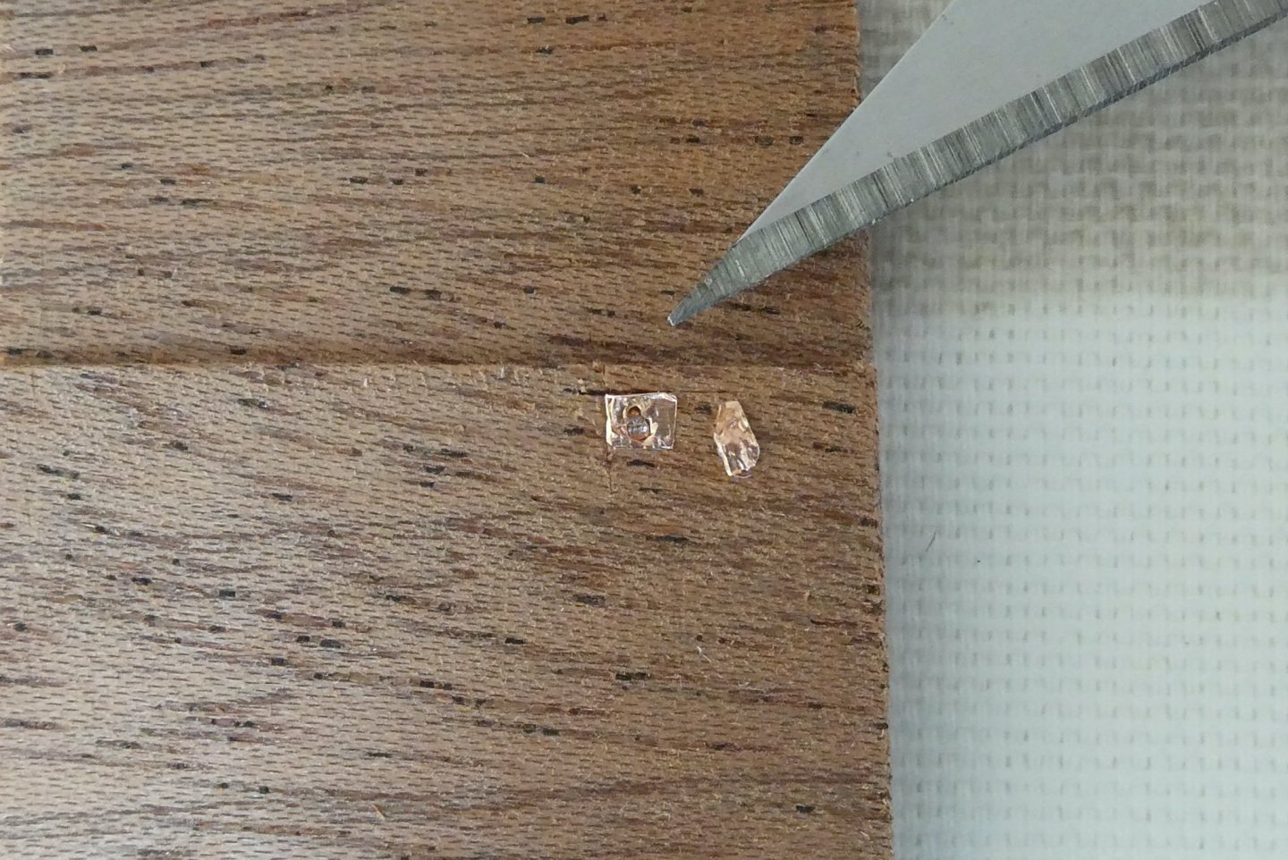
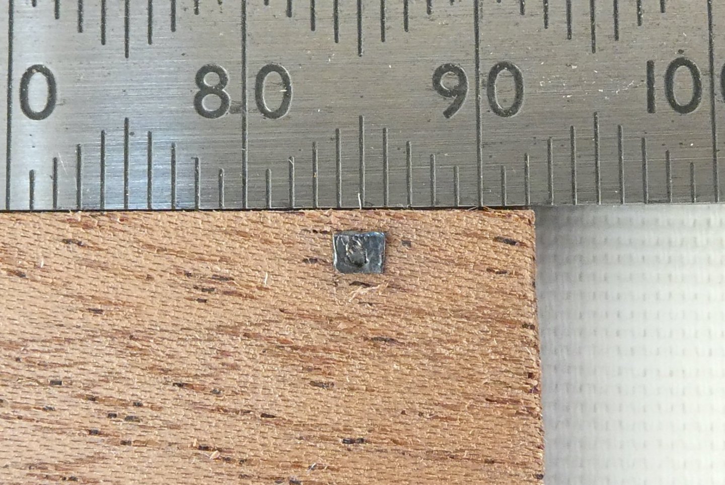
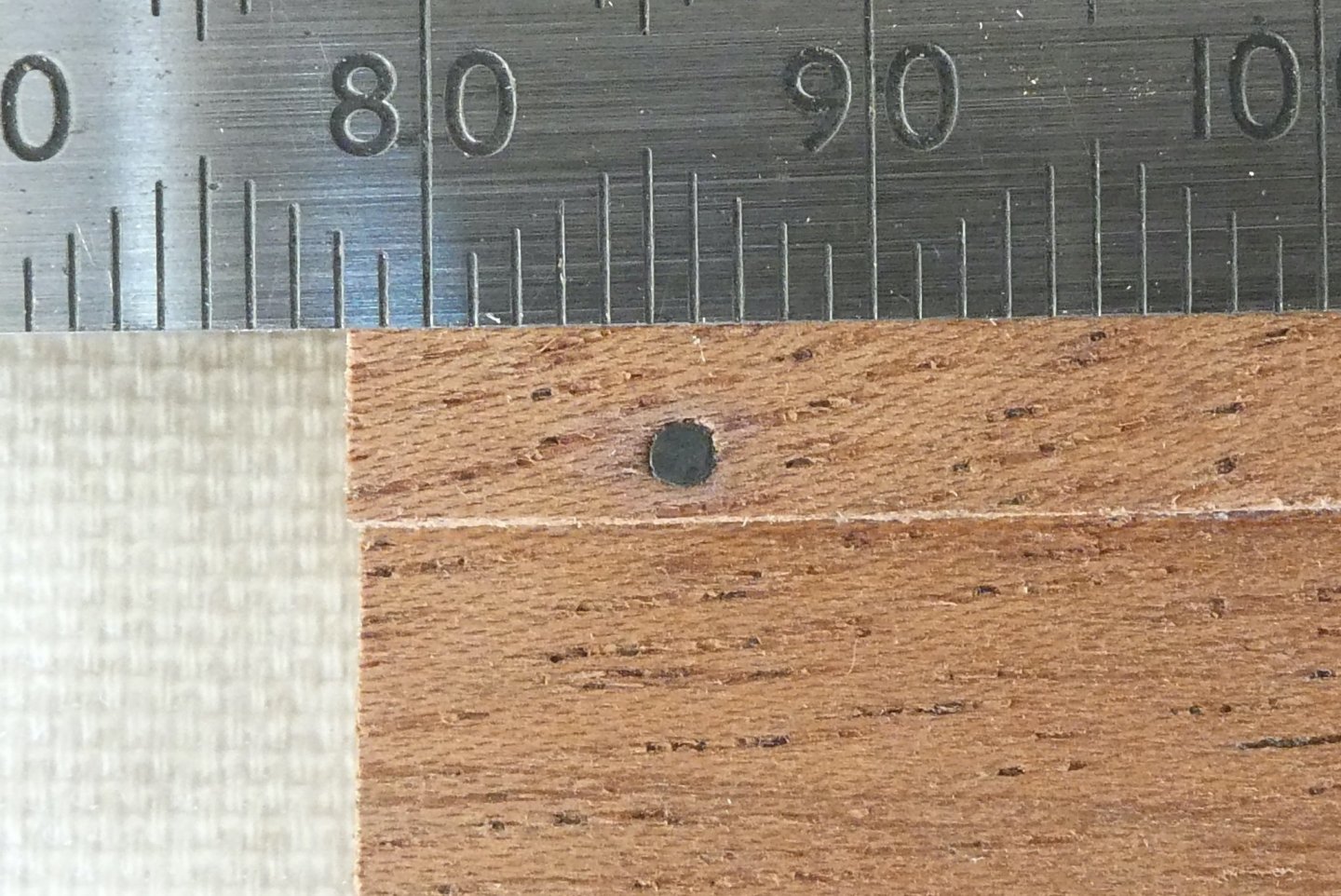
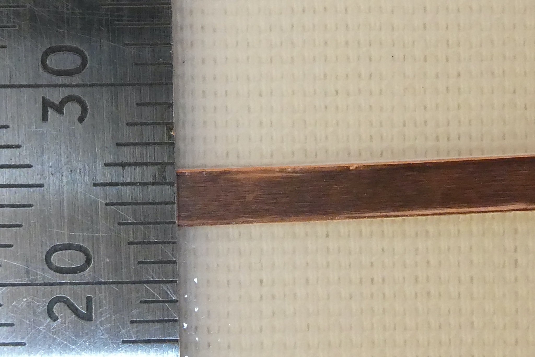
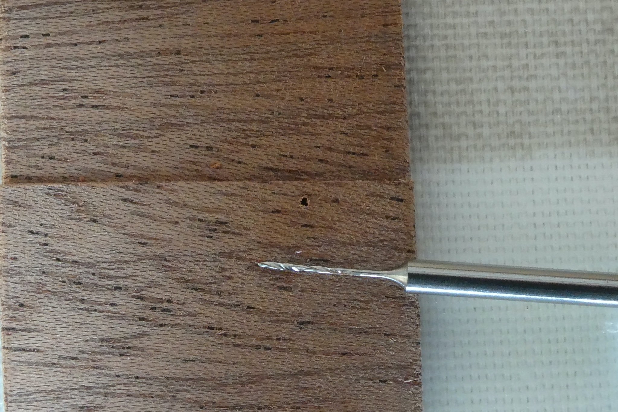
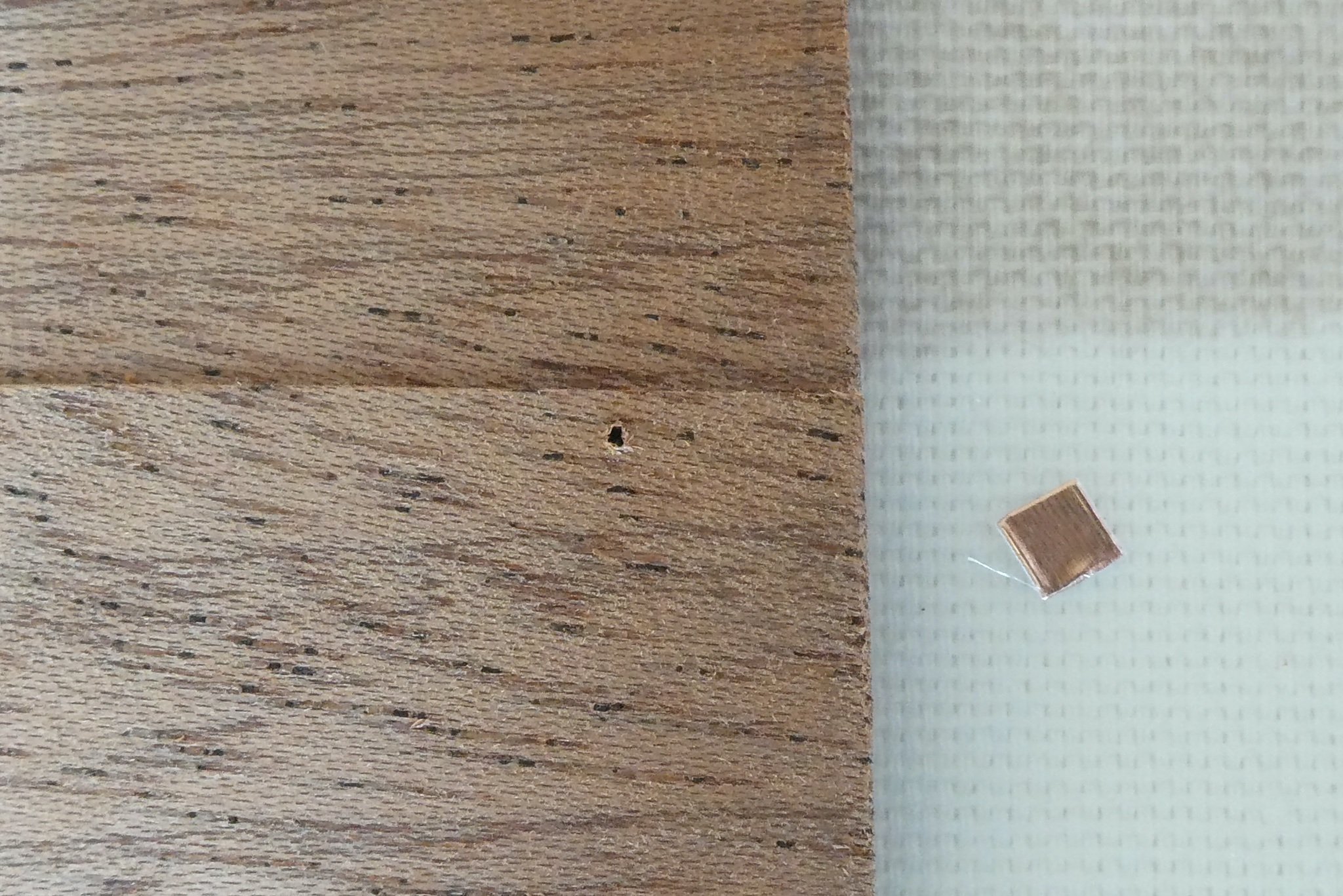
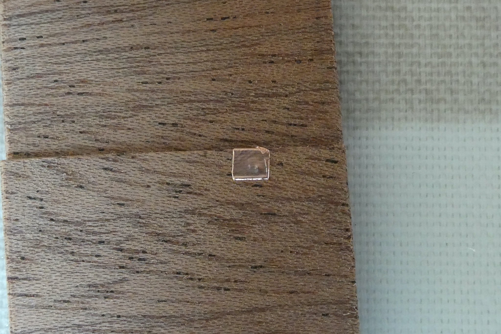
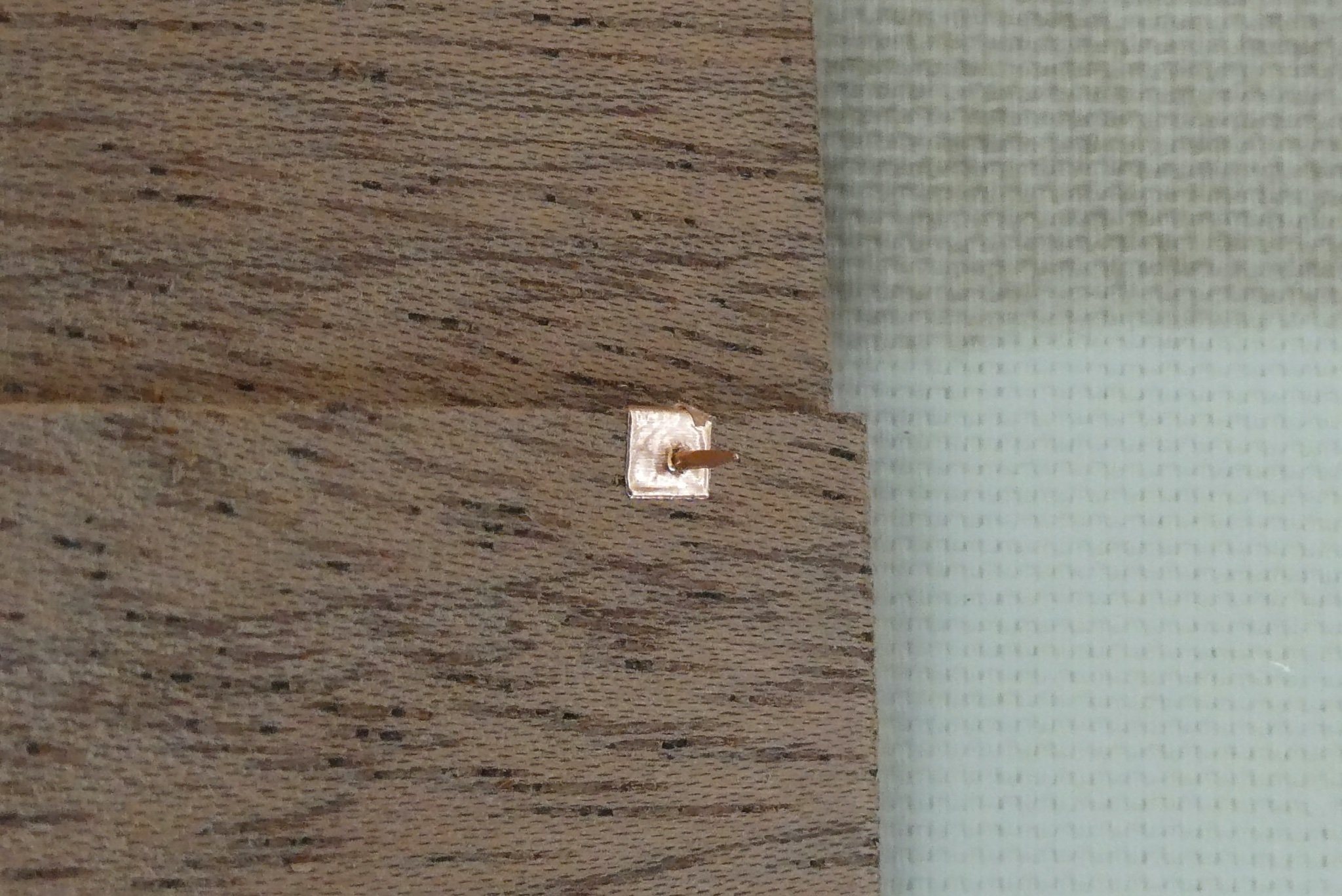
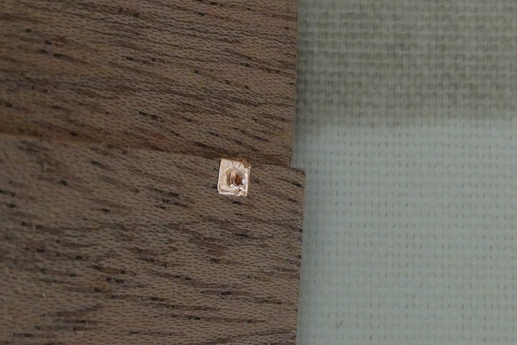
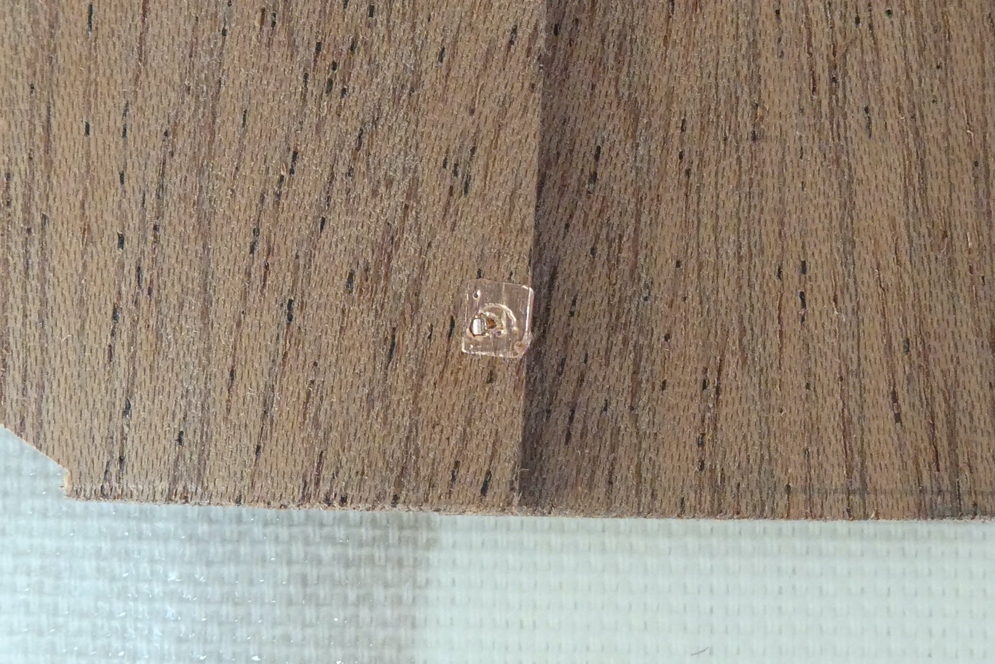
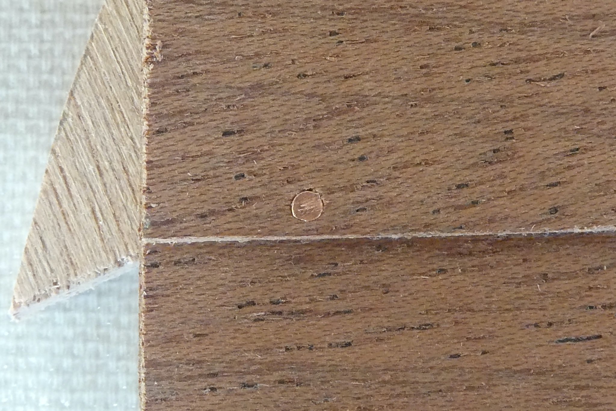
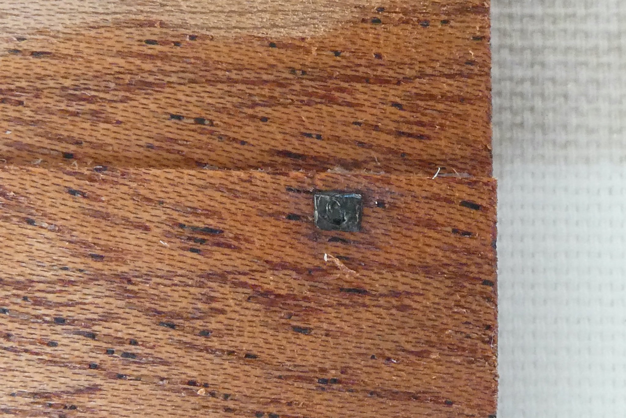
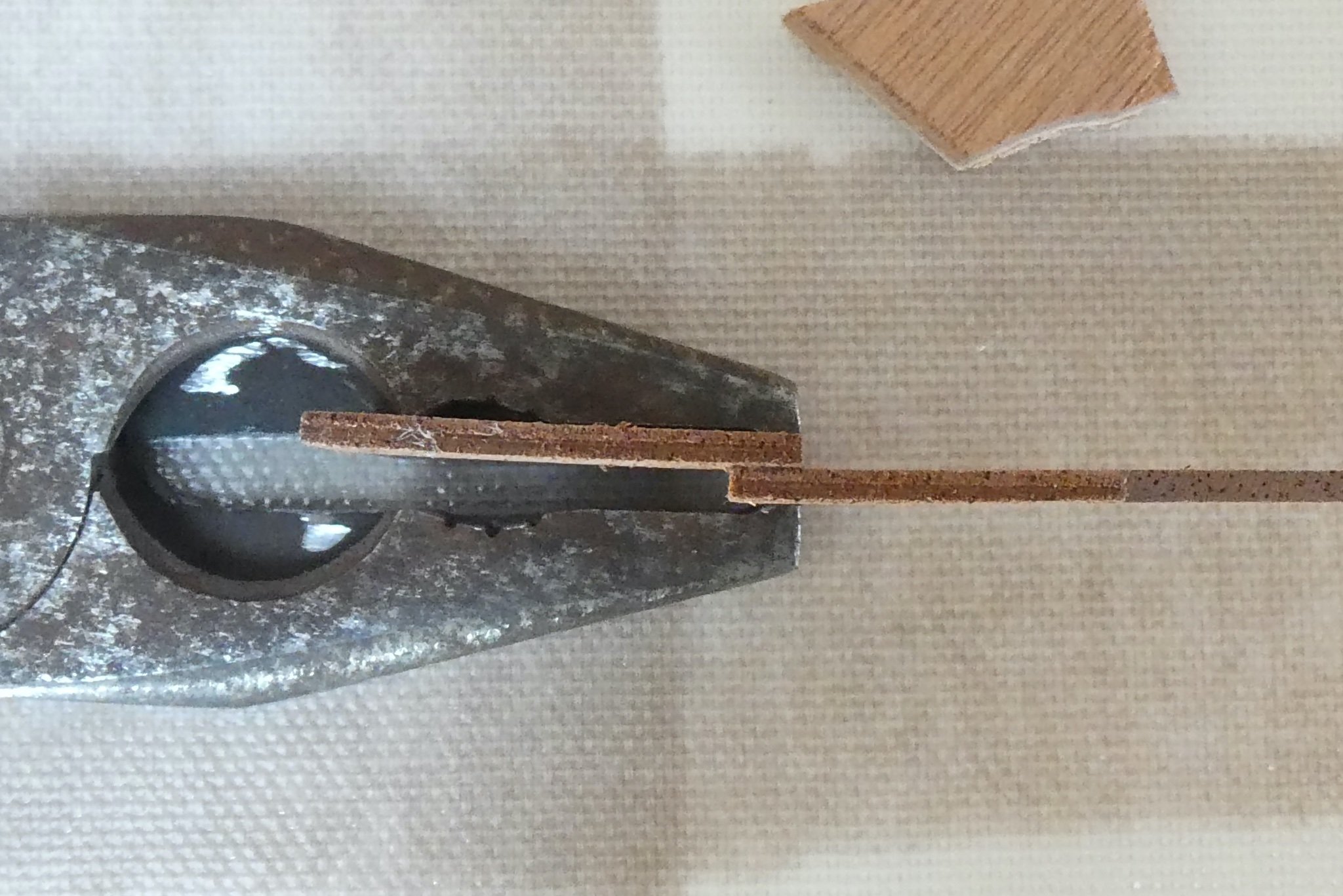
Riveting stuff! Sorry, I couldn't resist. So, back to the Vikings... Here is a run through the revised, revised version of my rivet-fixing process. The first set of photos are from yesterday morning, pre-Covid jab. I have not duplicated photos of steps shown in earlier posts. 1. Drill the hole for the rivet (as before). I toyed with the idea of putting the rove in place first, then drilling through from the inside but after a moment's thought discarded this idea since the crucial visual alignment has to be the external rivet heads. 2. Cut a small length of copper tape (as before). 3. Pin the rove to a cutting surface and then cut to size. I used a needle which was finer. I discovered two things at this stage. The good thing was that the cutting actually freed the backing paper making it much easier to separate but the cutting to size was actually easier to do before the pinning (the needle got in the way of the knife). 4. Put the needle with the 'skewered' rove into the predrilled hole and press into place. 5. Insert the copper nail into the hole, finishing off with what I now know is a rivet snap (as before) to dome the head (as before). 6. Cut off excess internal nail (as before) The next set of photos show the final result of the first complete one I did this morning: After patination This time I cut the rove before 'skewering' it. By this stage the rove is quite small so getting the needle in place (as central as possible) takes practice; it also reminded me why I started out by cutting the rove AFTER it was in place, although being able to cut onto a harder board than the strake made for a cleaner cut and avoided damage to the strake. As the pictures show the rove is still slightly bigger than it should be; the estimated size from the residual marks of iron on the excavated wreck is approximately 2x2.5 cm which would be 1x1.25mm at scale and this would leave hardly any copper around the needle. I'll see how small I can get. Lessons: This is fiddly work but a lot easier now than when I started, thanks to all your ideas and suggestions. Don't do this when tired (obvious) or within 18 hours of a Covid jab (my arm was really sore last night but now fine!). Magnifying spectacles would be really helpful (I've just ordered some). Doing the riveting this way (without any clenching) means the entire process could be done after the planking has been finished. This would means I could finish the smoothing, sanding and staining before any rivets and roves get in the way and are at risk of damage. Antony


-
That’s what I love about this site. Describe a process, ask for advice, and then laser-like come suggestions from members. Tomorrow morning the thrice-revised method will incorporate this brilliant suggestion (thanks Johnny) which should deal with the one bit I was really unhappy about, namely the cutting of the roves onto the wood of the strake. I should have time to try it out before going for my Covid booster jab. Will report back (on the roves, not the booster jab). Antony
-
Hi Christian, I think the discrepancy over the scale is a result of Billing Boats having produced 2 similar models. The first, the one I am building, is from their catalogue of 50+ years ago based on the original 1962 excavation report of Wreck 3 which was the only reference available when I first built the kit in the late 1960s. The full description of the Skuldelev finds was subsequently published in 2002 by The Viking Ship Museum, Roskilde, as Ships and Boats of the North Vol 4.1:The Skuldelev Ships I, Crumlin-Pedersen & Olaf Olsen (eds). In their figure 40, Torso-drawing of all preserved parts of the ship, the distance between upward projections of the prow and stern gives a distance of 13.9 m. On the kit plans this distance measures 670mm. The derived scale is 1/20.75 so I accept 1/20 is an approximation. A further confirmation comes from the 1/20 scale drawing of the excavated keelson (figure 28) which measures 185mm compared to a measurement on the Billing Boats plan of 184mm. Billing Boats current model is the Roar Ege which is based on the Roskilde Museum reconstruction of Wreck 3 rather than the original and so differs in some details but not size. This has an advertised scale of 1/25. At whatever scale I think it is an elegant craft! Antony
-
Steven, that’s an impressive piece of metalwork. Maybe a resurgence of hand-to-hand combat on the Sussex Downs will make people realise what they’ve lost! Did the Saxons do any better in the replay? Antony
-
Hi Steven. Thanks for that information. Just shows there’s nothing new under the sun, except my ignorance! Antony
-
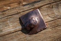
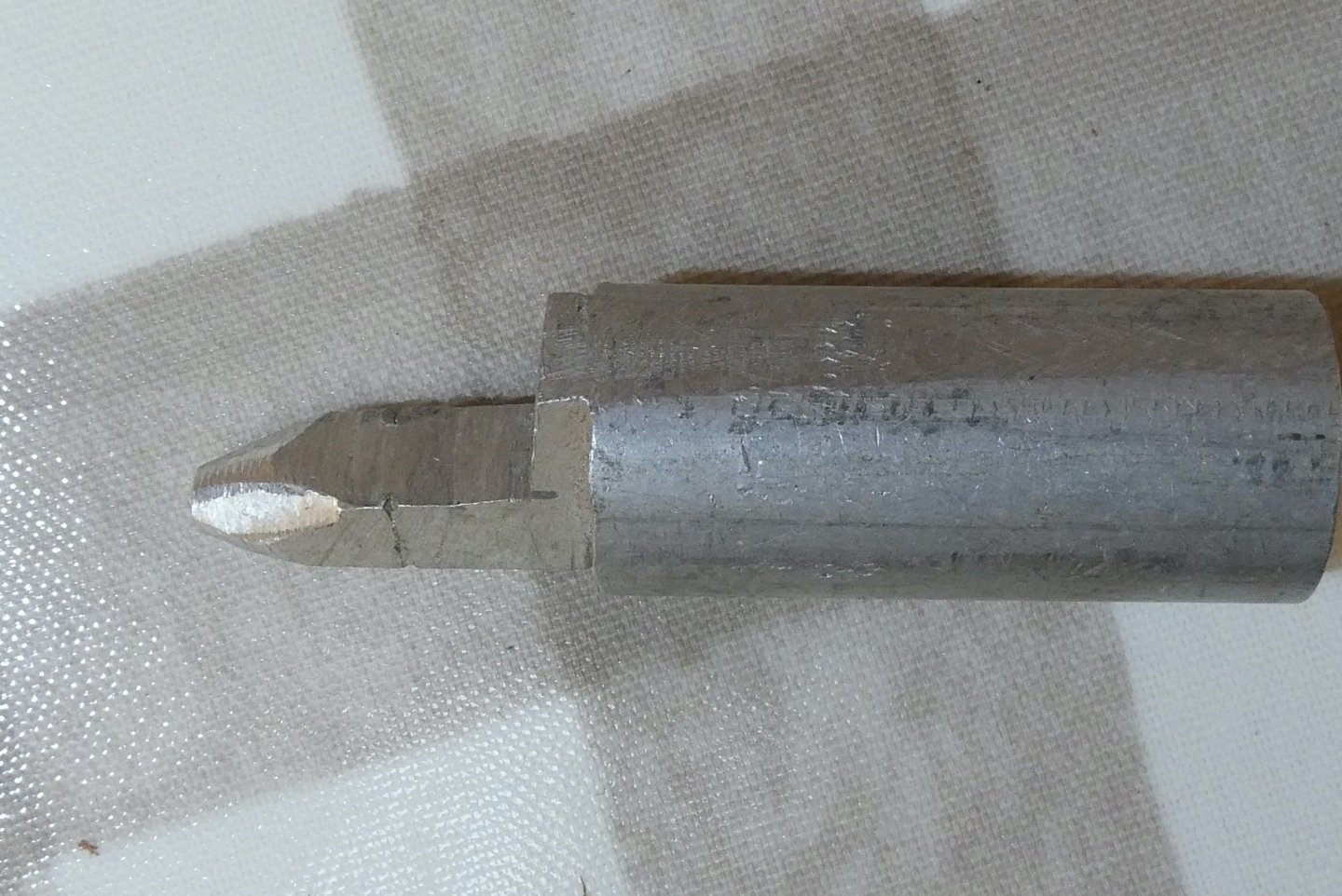
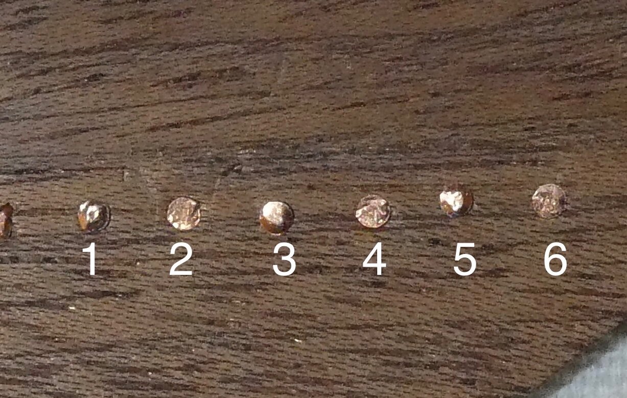
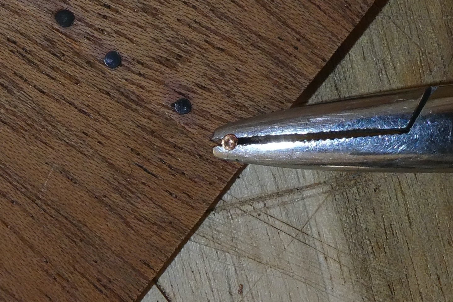
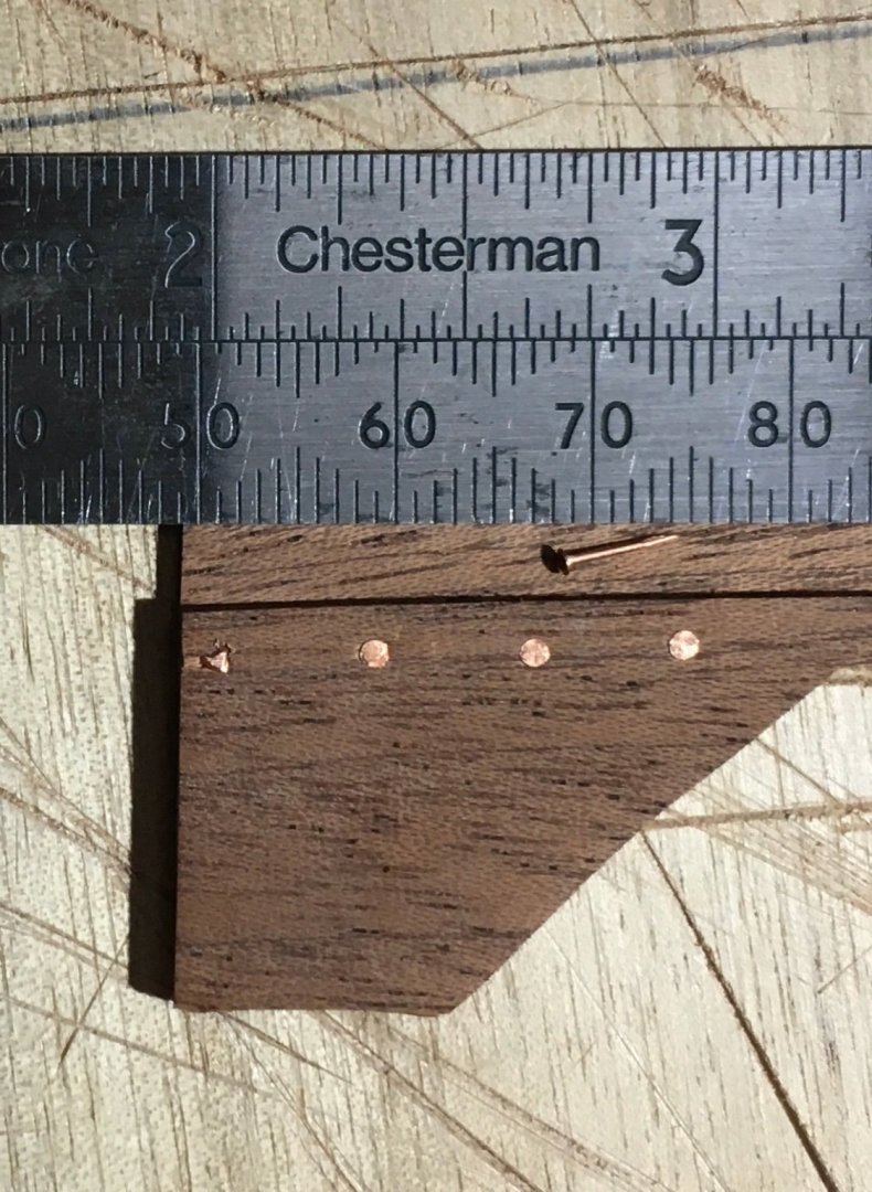
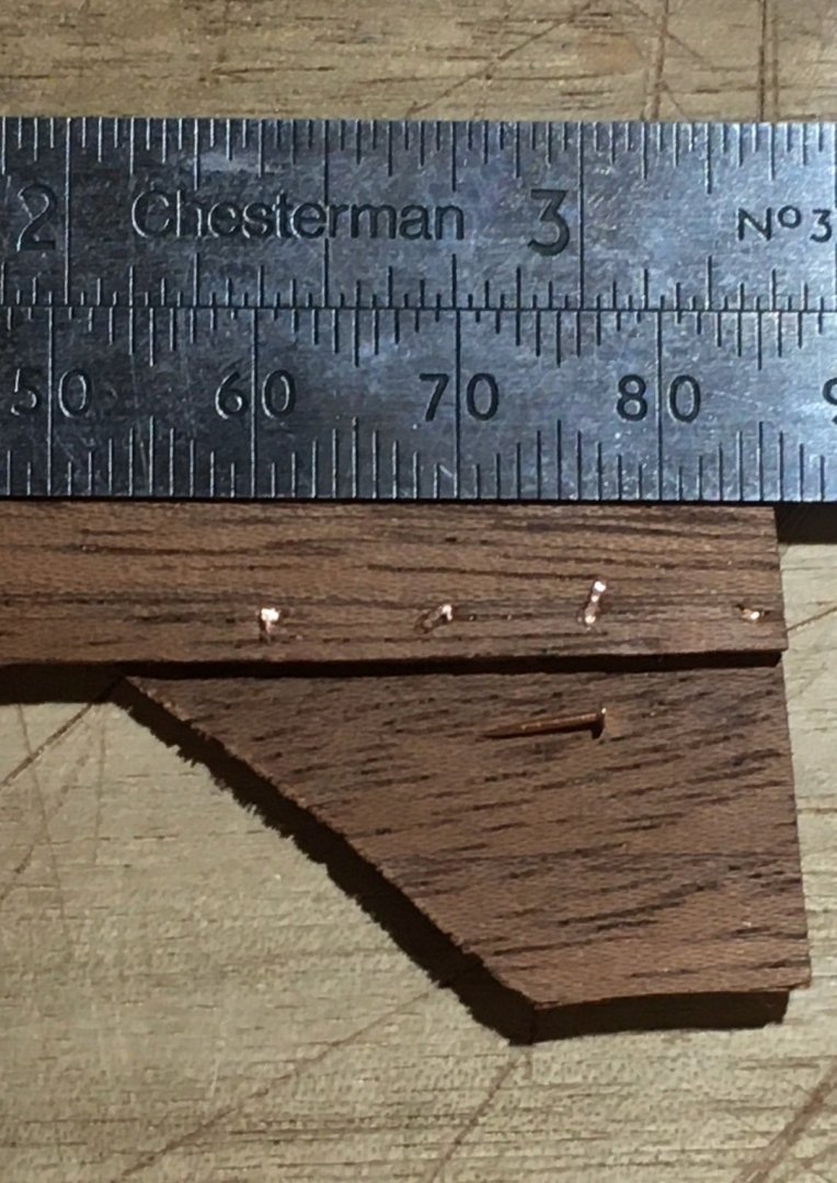
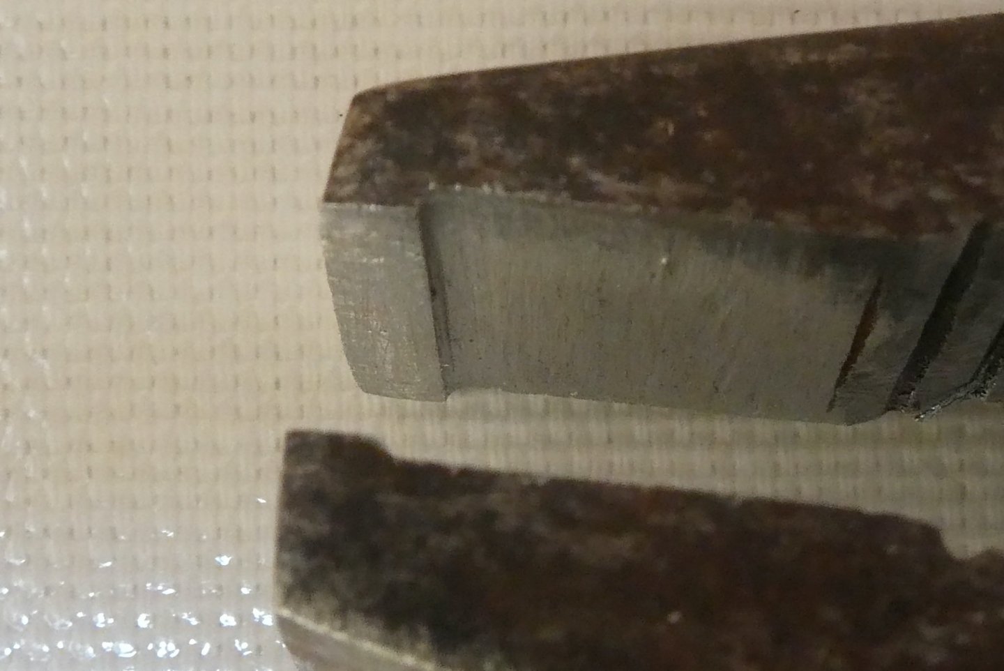
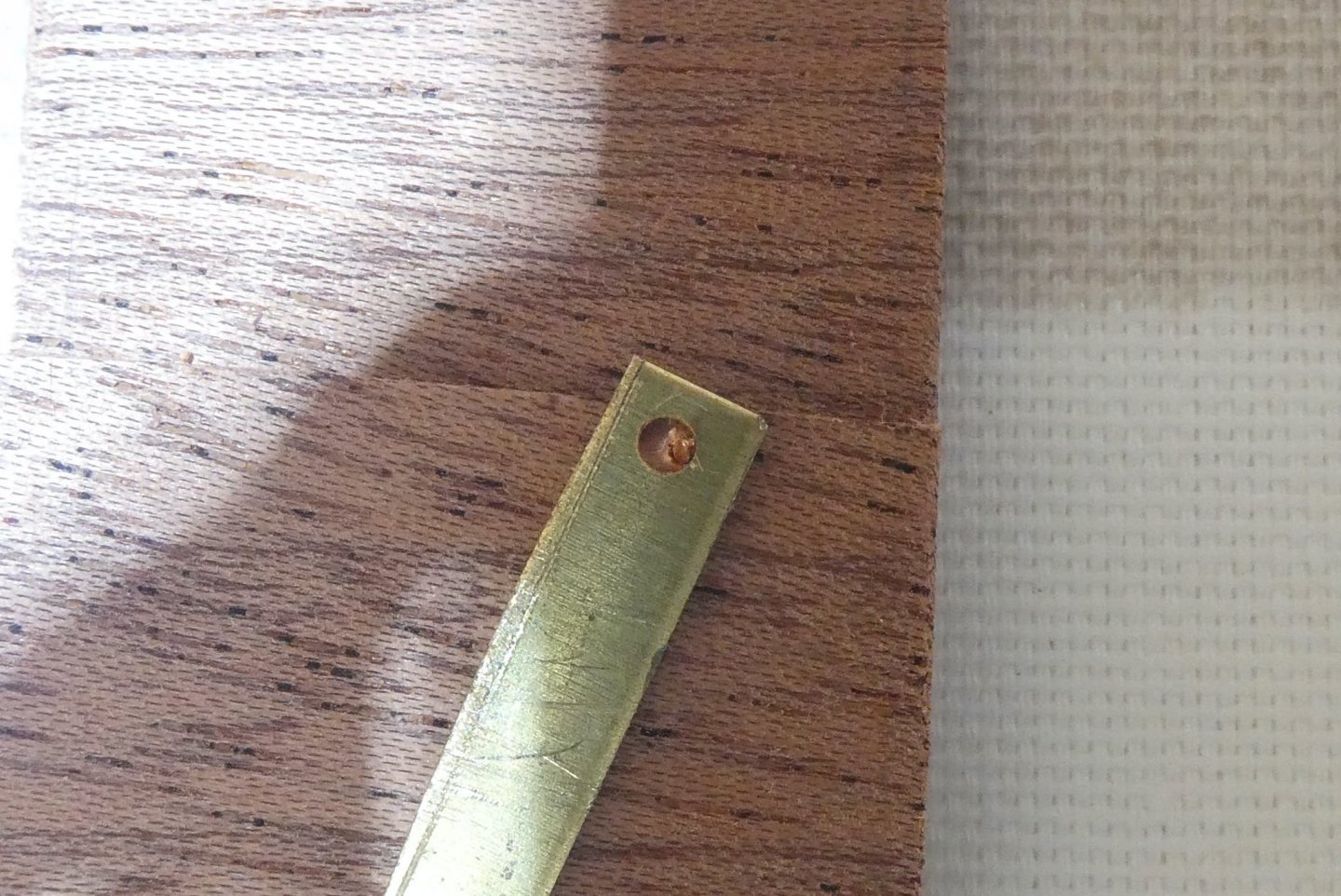
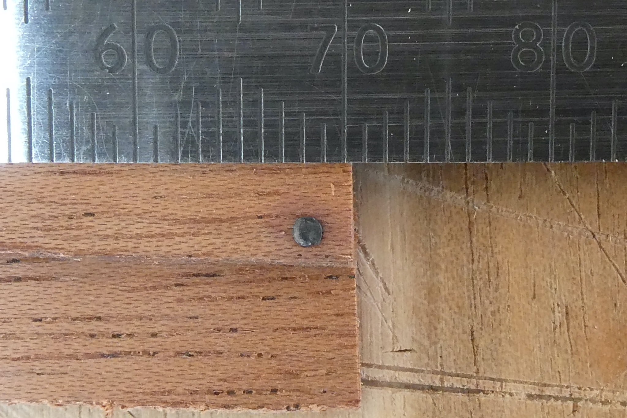
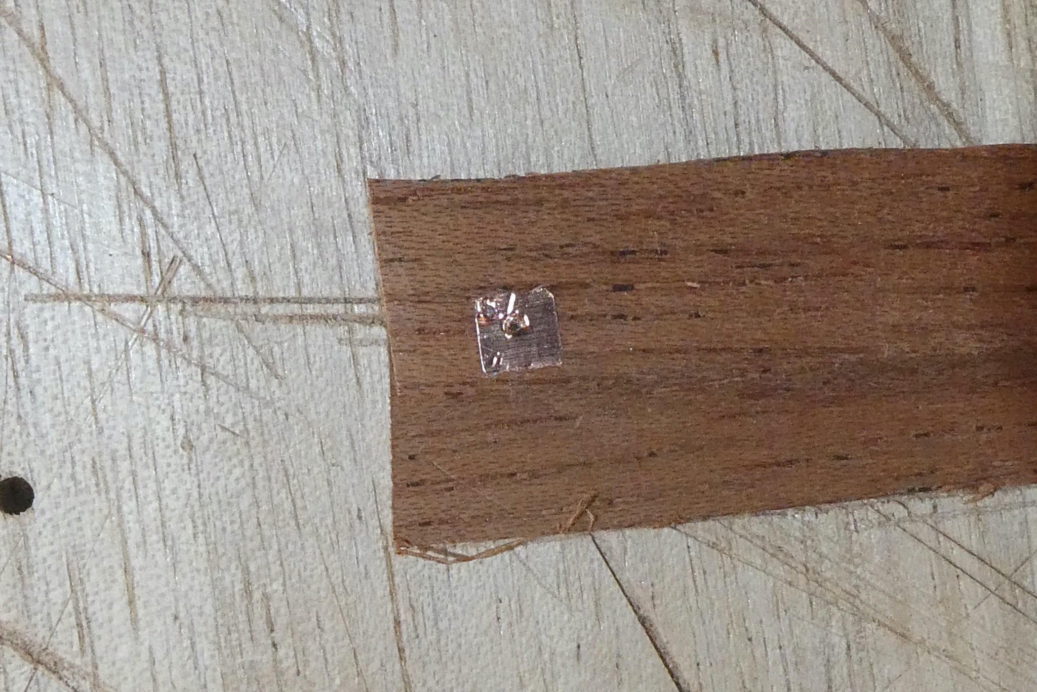
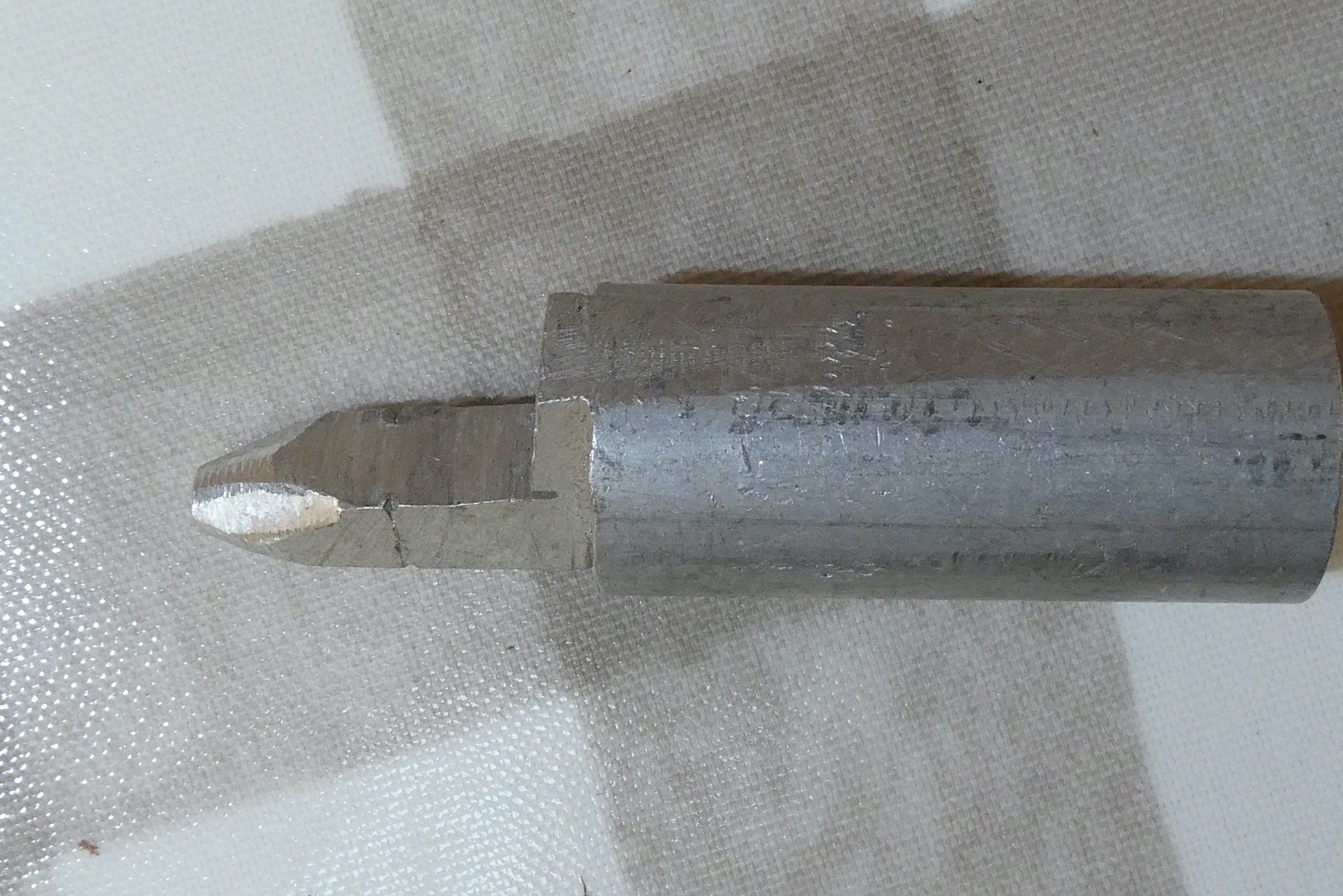
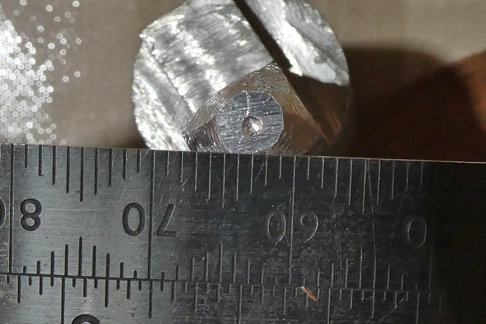
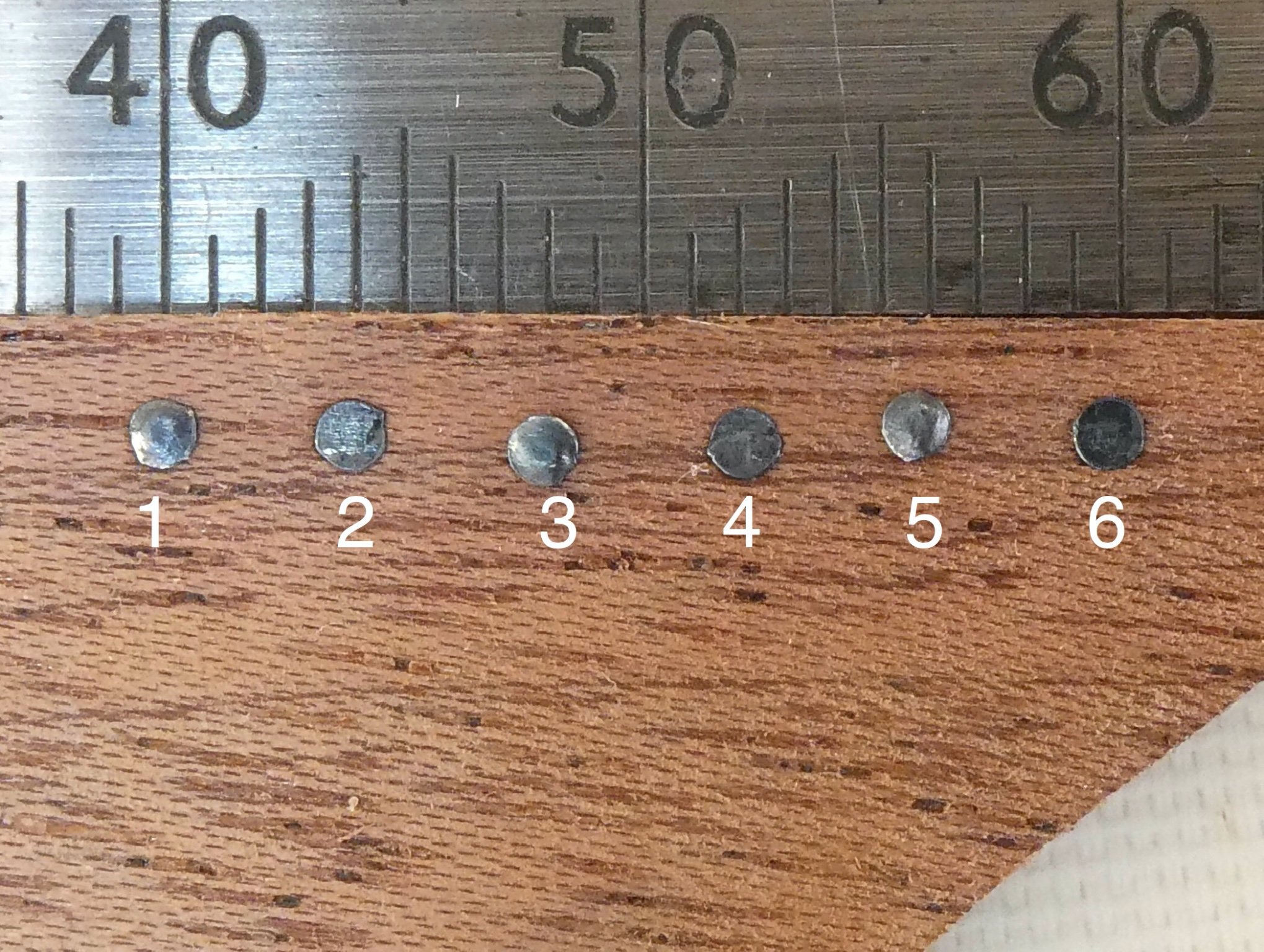
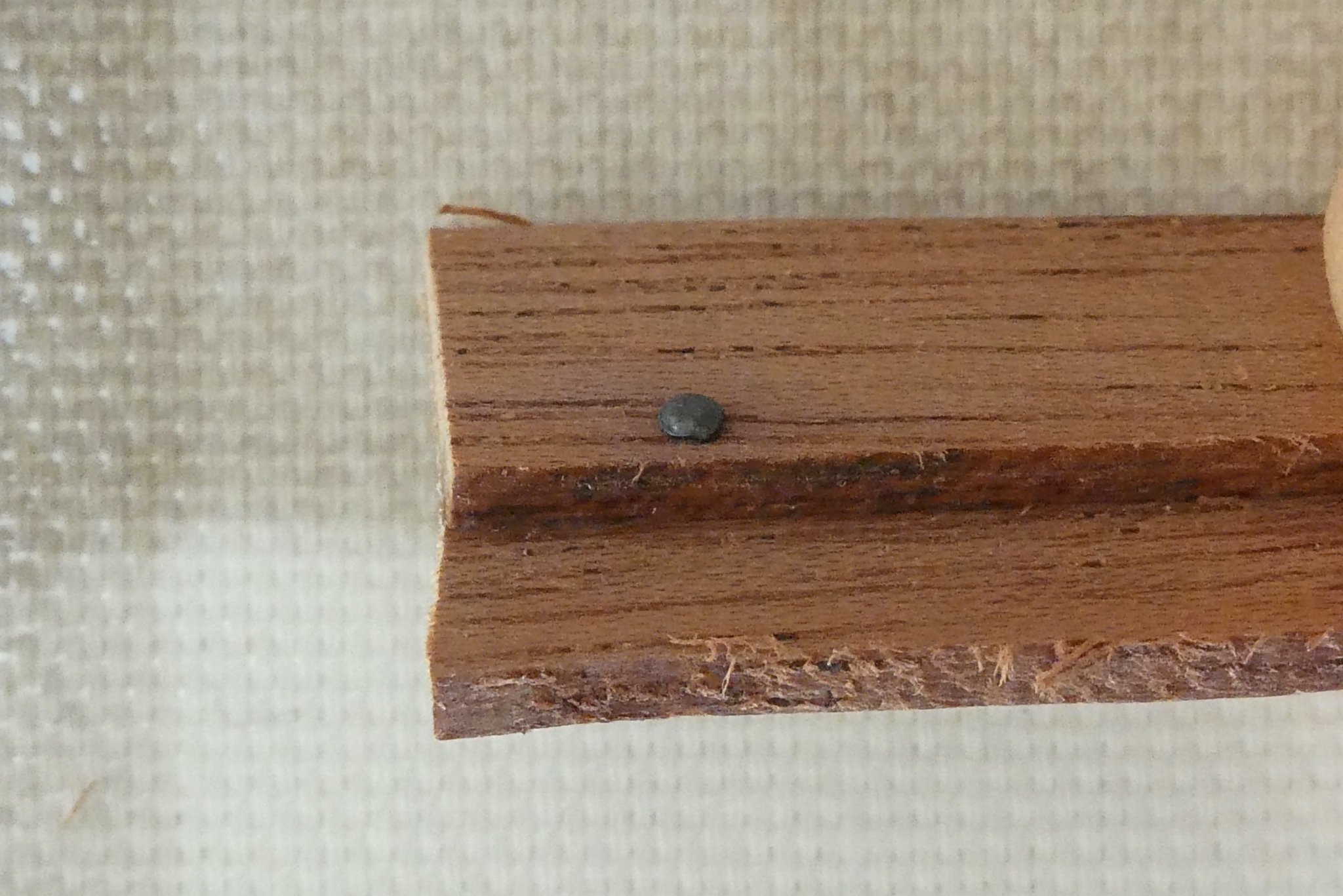
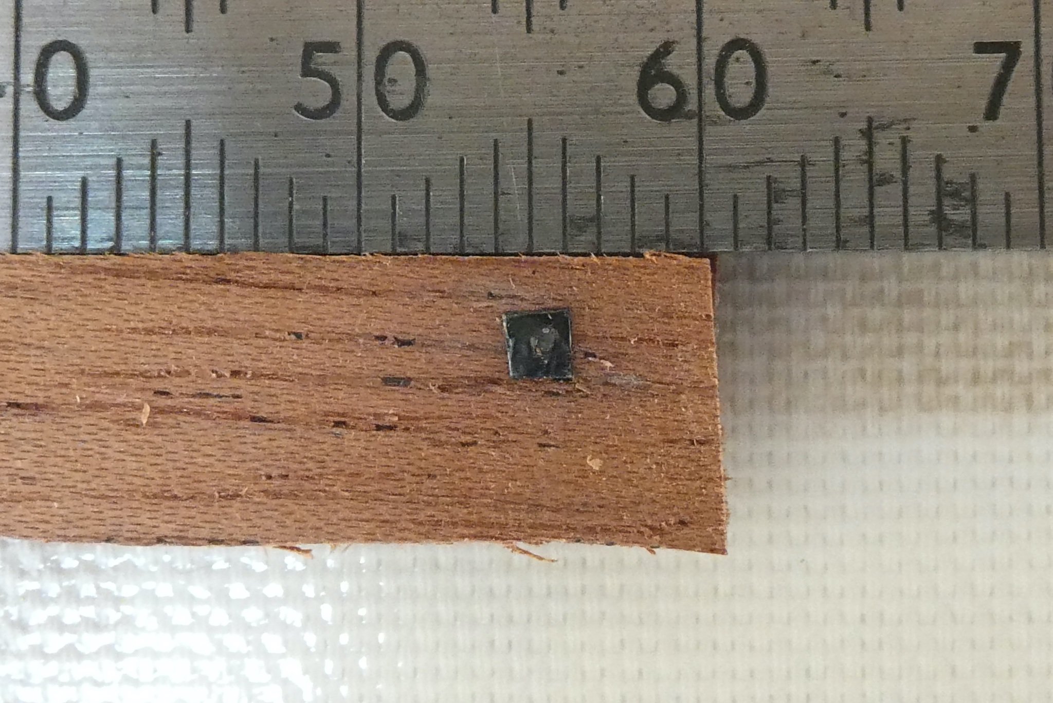
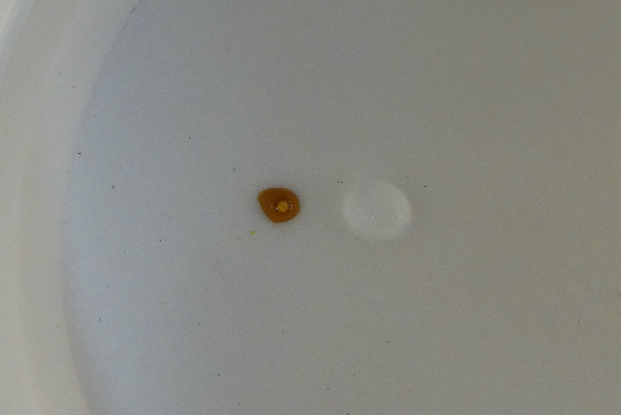
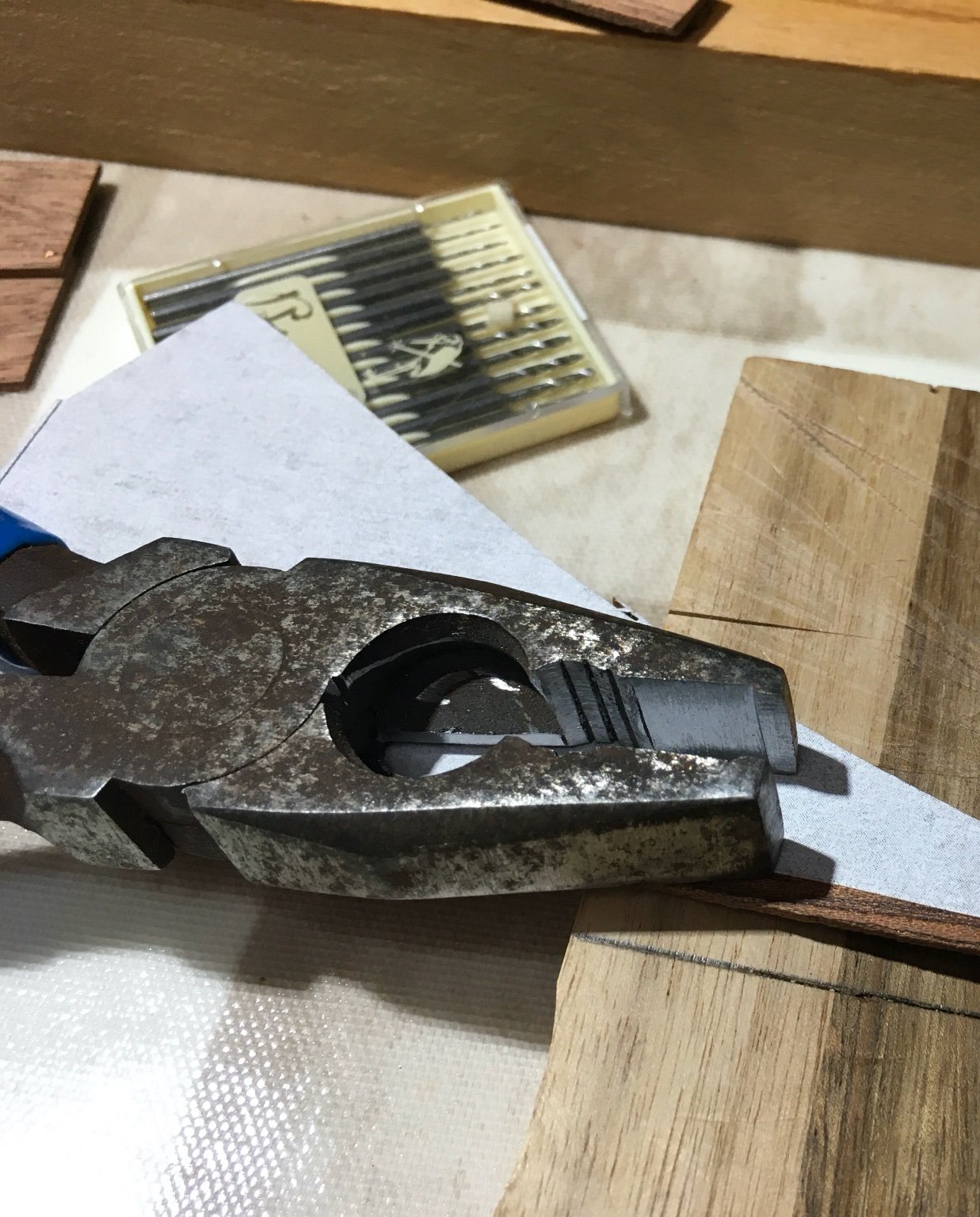
Thank you everyone who posted such useful and helpful comments and advice. It prompted me to examine the rationale of the way I was trying to achieve the effect I wanted. This is the effect I'm seeking: This image is from Roskilde Viking Ship Museum website describing the reconstruction of Wreck 3. https://www.vikingeskibsmuseet.dk/en/news/iron-in-the-viking-ships-rivets-and-roves They are using copper because of the problems with iron and sea water, as well as the properties of modern iron. Although I am using copper my intention remains to simulate iron. So, why did I start doing it the way I did? 1. The Vikings did it that way but they also worked outside in the open air with axes and had someone else inside holding the rivet, so maybe not a good argument. 2. I wanted to avoid using glue because of the lesson of 50 years ago and the effect unwanted glue had on any stain application; clenching seemed to proved a way of keeping the nail in place. An unwanted effect of clenching proved to be the unsatisfactory degree to which the nail head was flattened onto/into the strake. In my initial experiments I found that with a 0.5mm ø hole it was possible to unwittingly bend the nail as it was being pushed in and for that reason I changed to using a 0.6mm ø hole. The nail goes in easier and when pushed through the rove is gripped by it and by using a different type of cutter (a cuticle cutter rather than a nail clipper) the inner end of the cut nail is slightly flattened and spread and so held firmly in place. With this approach (no compression) the nail head could be left slightly proud, not ideal but at least less flush than before. These are the clippers and the internal cut end of the nail: BUT if the nail is soft enough for the shaft to be deformed so easily maybe the head alone can be rounded with a profiled 'pusher' as suggested by Johnny. Using an old piece of aluminium I fashioned a tool to use as a pusher with a dimple slightly smaller than the nail head diameter which I could use to 'dome' the nail head. This approach would require pushing against some resistance but to do this after inserting the nail would require an 'anvil', with the complication of working on both sides of the strake, or the use of a pair of further modified pliers. It would also be complicated by the need to apply just enough force to deform the head but not so much that the nail head pushed too far into the strake. I realised that the opposing force could be achieved by returning to the smaller tighter 0.5mm ø hole and rely on resistance from that. And so it proved. I found my 'pusher' was working against sufficient resistance to dome the head slightly (a twisting motion helped) before pushing it though the rove at which point the inner end could be cut off. This shows the comparison. 1, 3 & 5 have been domed with the 'pusher'. 2, 4 & 6 were inserted using my clenching pliers. I should say that the spacing is not what will be used on the ship and was done this way to make comparison easier. Before patination: After patination: To prevent any risk of bending the nail with the 'pusher' I use a surgical needle holder initially, then push the last bit in with the doming tool. This a complete rivet and rove assembly after patination. The rivet stands proud with a nice domed profile and the rove simulates the full size even though it is flatter than would have been the case in real life: I'm pretty pleased with the results! Whether I will still feel the same after doing 1300 remains to be seen. I benefited so much from everyone's earlier comments and I suspect there are still ways of doing this better (or easier) so all advice will be gratefully received. Antony


-
Thanks for that suggestion; I’ll take a look at the Medway instructions. I need to take a look at the potential space, especially near the stem and stern, to see if there is any chance of getting the pliers in. Of course since some of these spaces will be invisible under decking and I could always leave off the roves although somehow that feels a bit like cheating!
-
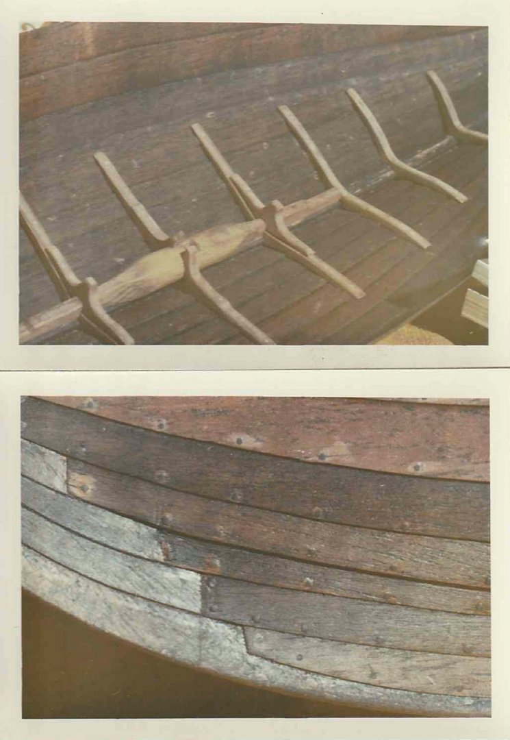
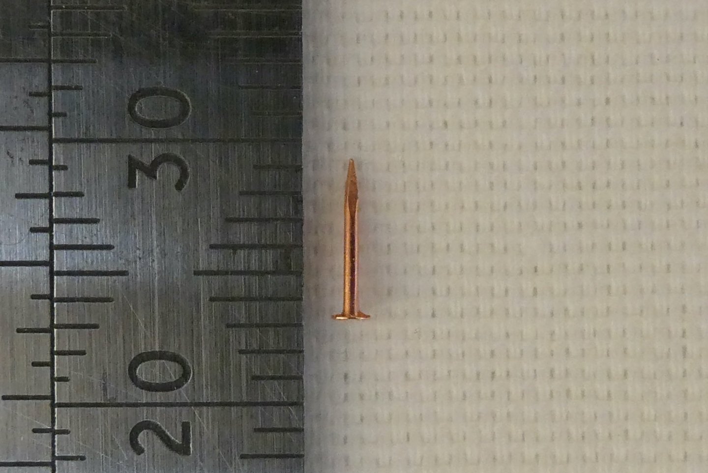
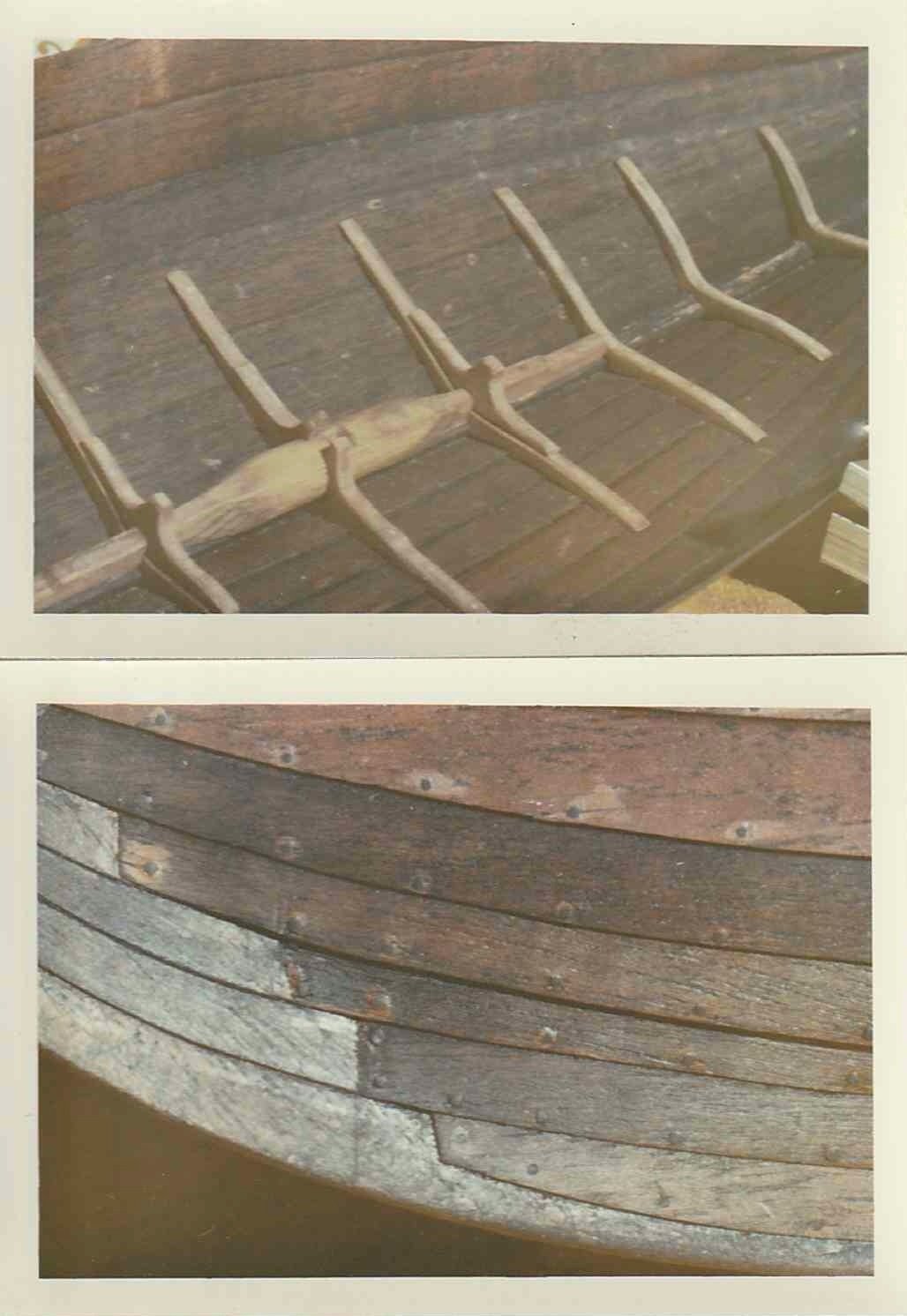
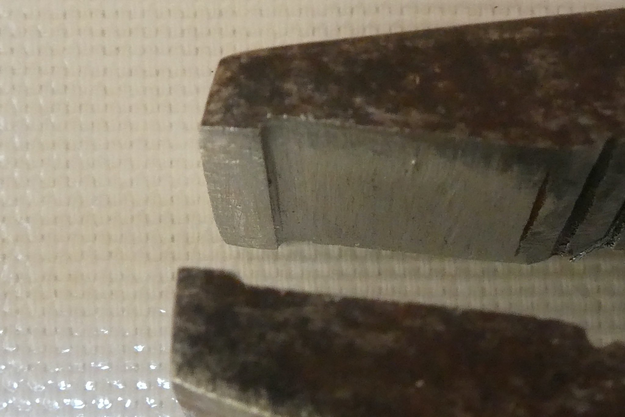
Rivets When I set out to build this kit again one of the things I was determined on was to make a better stab at the rivets holding the clinker built hull together. Sorting through some old photos at the weekend I came across three from 1970 of my first effort. I had forgotten even taking the photos but I do remember being inordinately pleased with the result; looking back over 50 years I conclude this was youthful enthusiasm rather than an objective assessment, although much of the problem relates to the effect of excess glue preventing proper staining of the wood. There were no internal roves. Inside view (Upper) and outside view at junction with stem piece (Lower) This time round I thought I would try to emulate the rivets by using the smallest copper nails I could find consistent with the 1/20 scale although the roves might prove to be a problem. Copper has the advantage of being soft enough to cut or clench easily and it can also be patinated to grey/black simulating the original iron. Copper Nail Initially I tried clenching which was easy using a regular pair of pliers but I then ground the jaw profile so that the jaws could reach over the strake and controllably apply pressure solely to the nail. Modified Pliers Unfortunately the results, although quite pleasing visually, were quite inappropriate for the period (mid-11C). External view of initial attempts Internal view showing clenched nails This left me with no option but to consider how to make the roves. I decided on 3mm (actually closer to 2.5 mm) wide adhesive copper foil. This was sold as slug deterrent to fix around flower pot rims. I have no idea of its efficacy but it proved to fill the need for model ship building. What follows is a run-though of a test undertaken on some scrap wood cut to emulate the size and thickness of the strakes. The 'strakes' were first fixed with PVA glue. 1. Drill a 0.5 mm ø hole 2. Cut a 2-3mm length (approx) of copper tape 3. Peel tape from backing and stick copper tape over hole pressing hard onto wood 4. Push nail through hole from outside and right through the copper tape 5. Trim nail internally using a brass template (for thickness) to leave 0.75 mm protruding 6. Clench internally protruding nail remnant using modified pliers Side view Internal view External view 7. Trim excess copper tape 8. Mix up liver of sulphur gel and water (for the test I used a single drop) and apply to clenched nail and head Wash off once desired patination is achieved Rove after patination and washing Rove after drying Rivet head after patination Comments The nail heads do not protrude as would have been the case with the original forged iron rivets, an effect which ironically was quite well achieved with the bamboo pins I used originally. I could probably reduce further the length of internally protruding nail before clenching although once patinated the effect is quite convincing. Although this method works technically and produces a quite acceptable (to me anyway) result it may prove a lot more difficult when done in the confined hull space once a strake is fixed. Although this method can only be used as each strake is fixed (with attendant demounting and remounting of the hull on the framing jig) it is conceivable that a 'long reach clencher' could be designed or even built. Before I embark on this as a solution (my initial estimate of 1300 rivets feels quite daunting) I would appreciate any thoughts, suggestions or criticism from all of you with far more experience than me. Antony


-
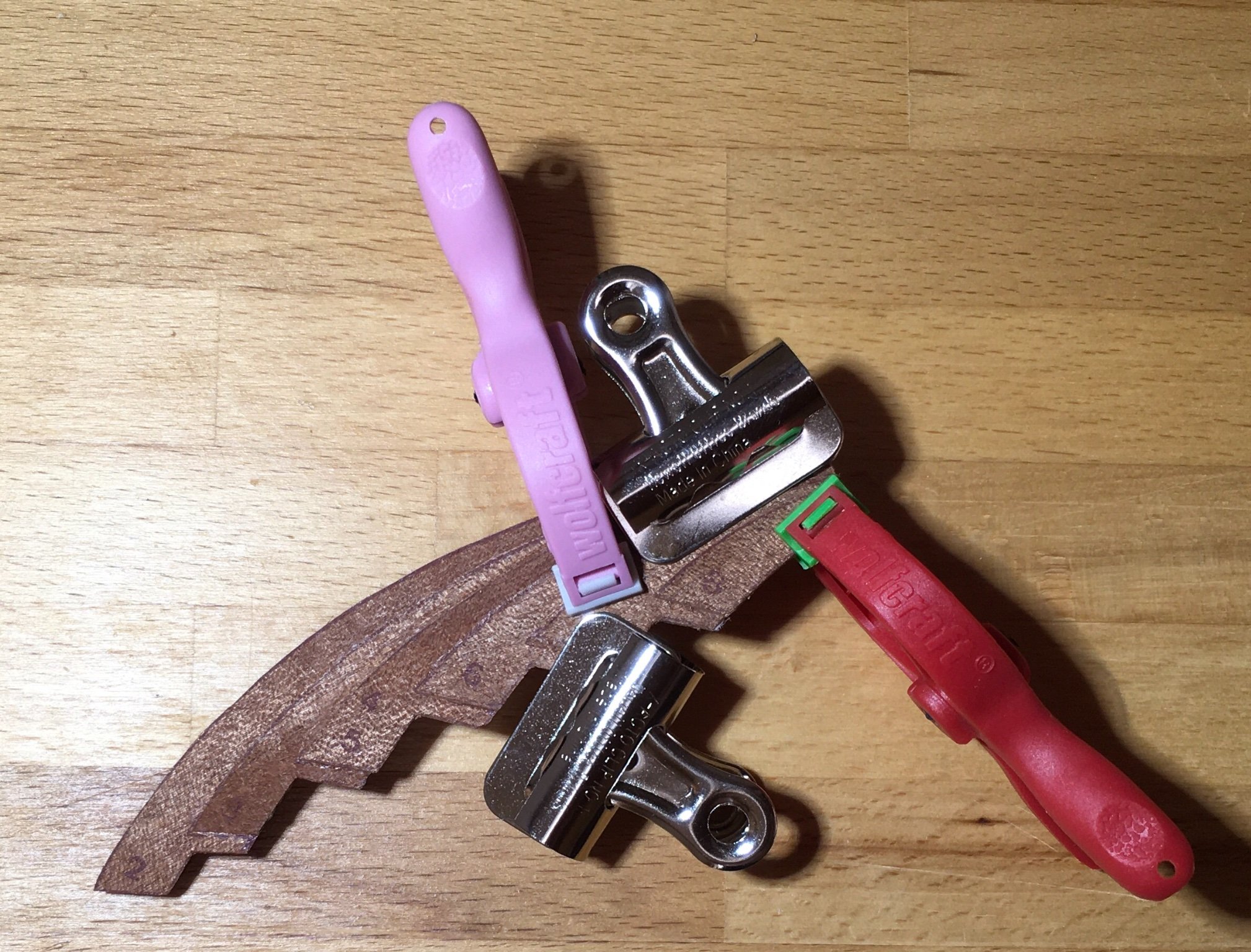
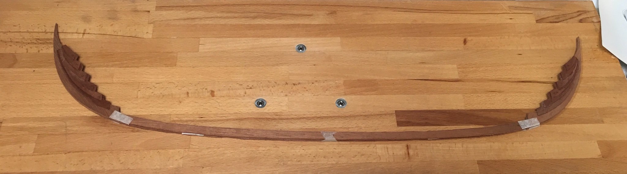
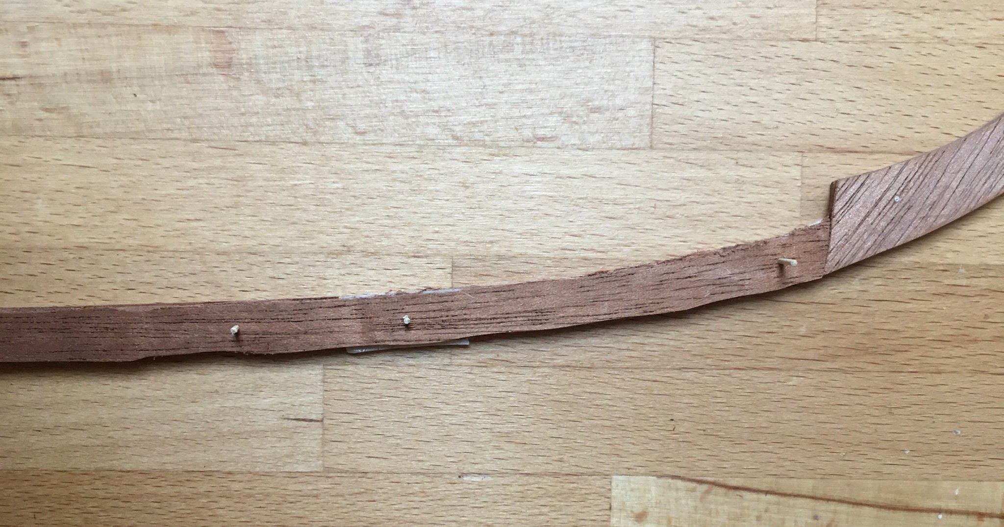
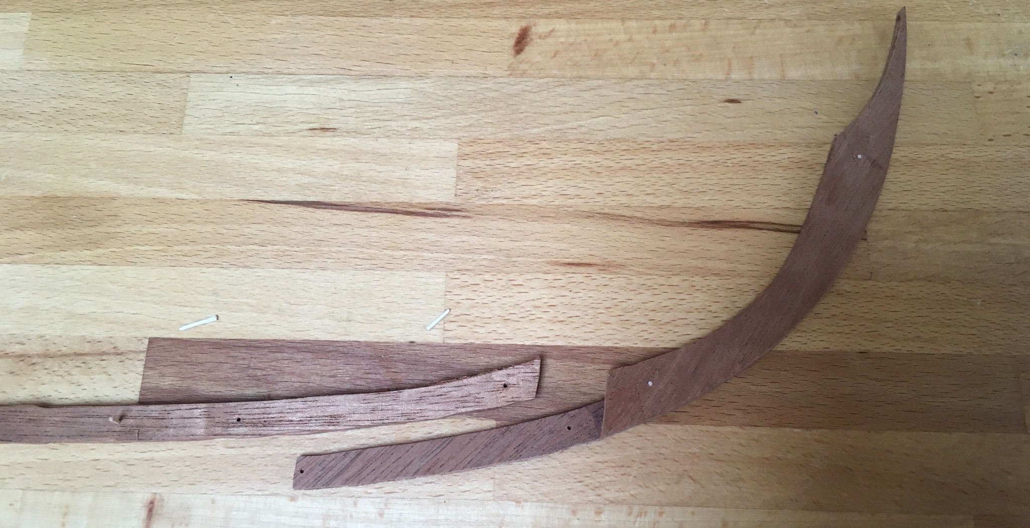
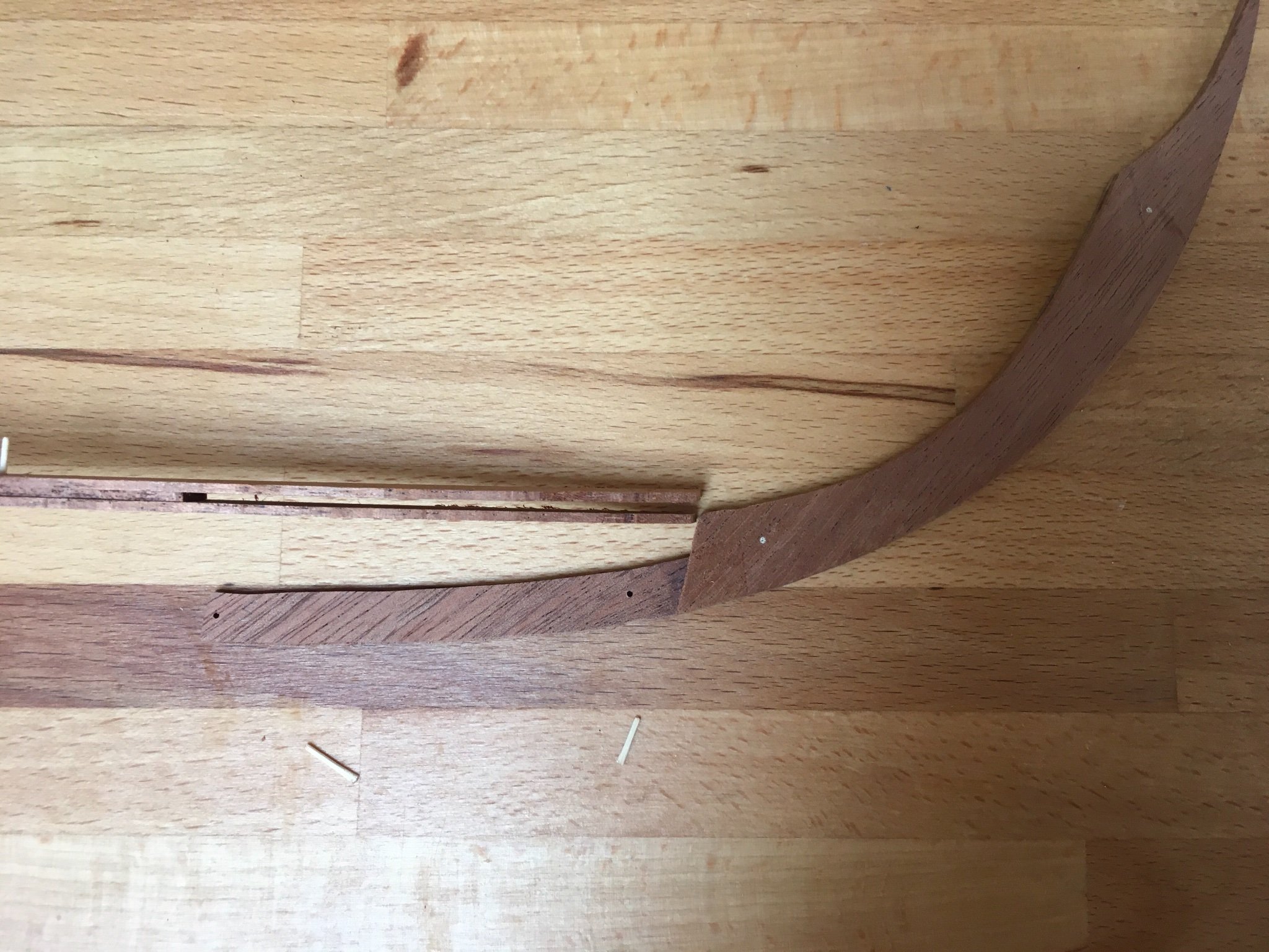
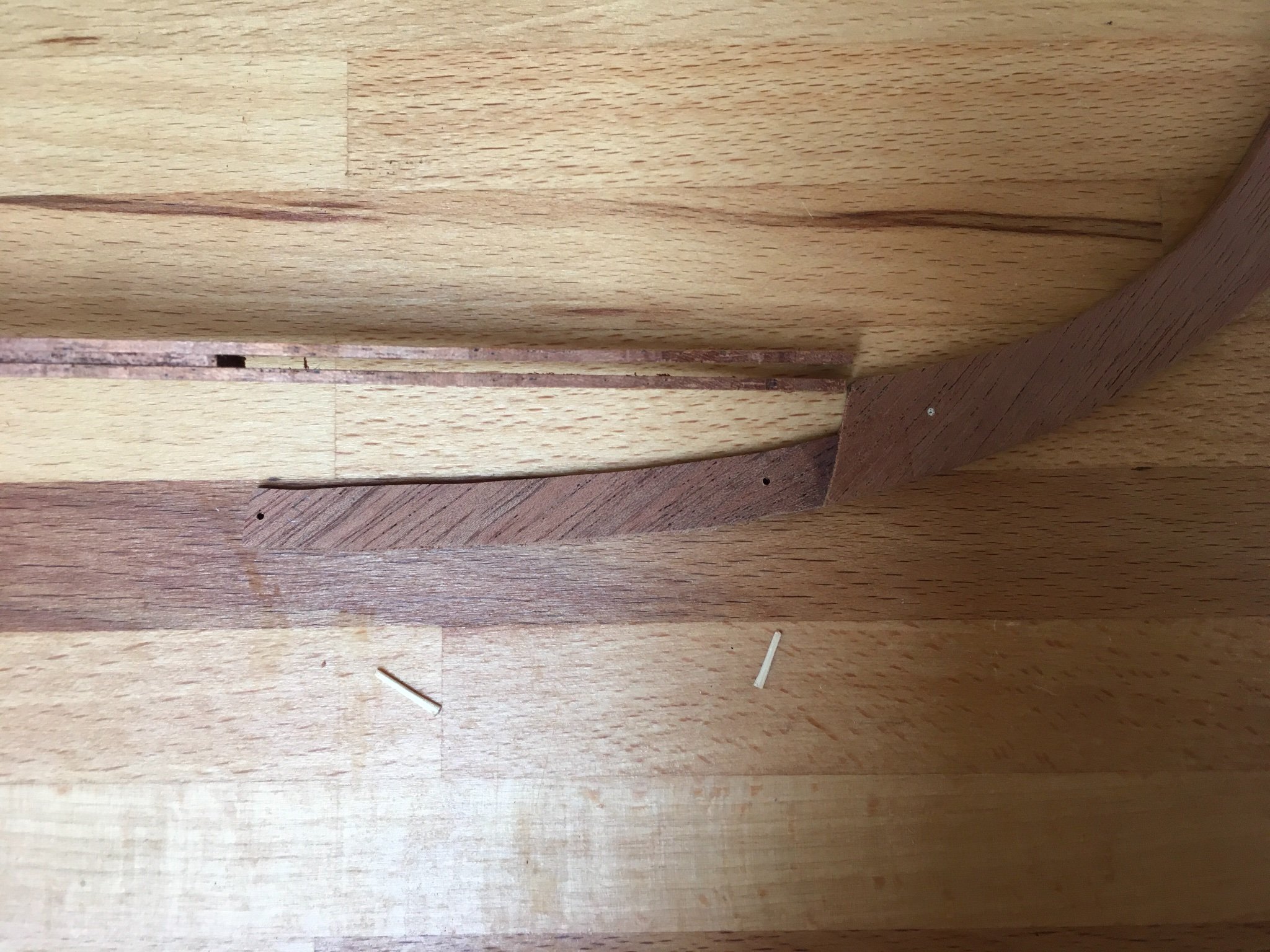
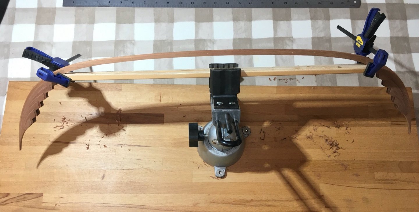
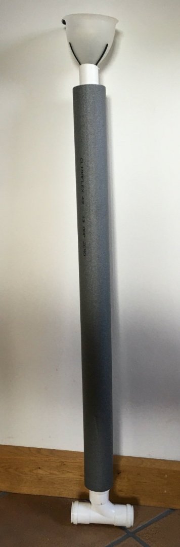
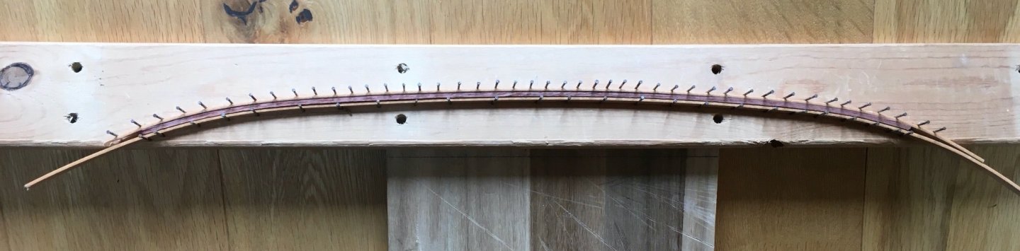
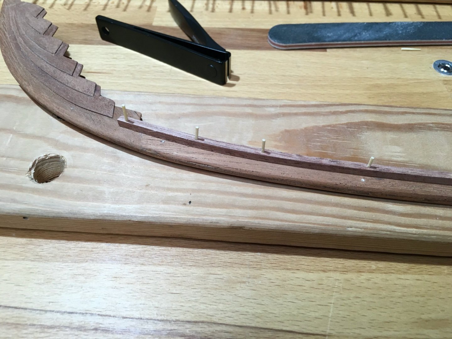
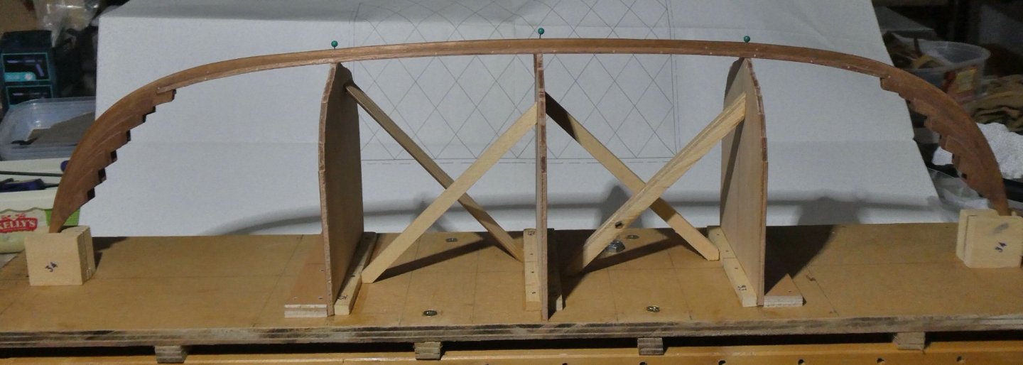
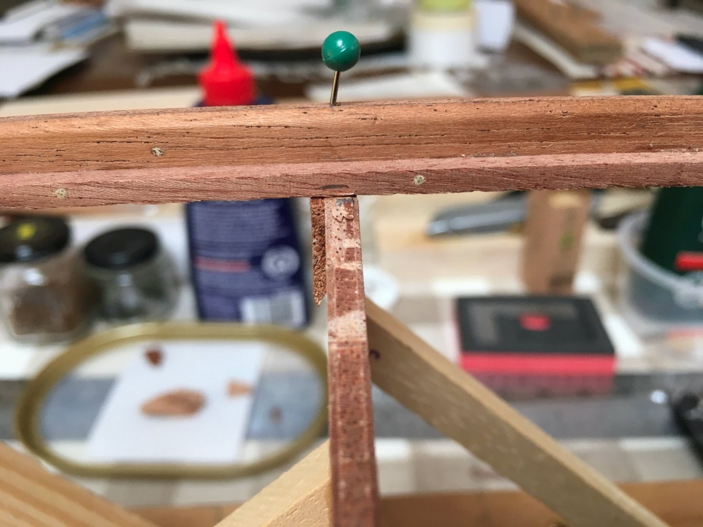
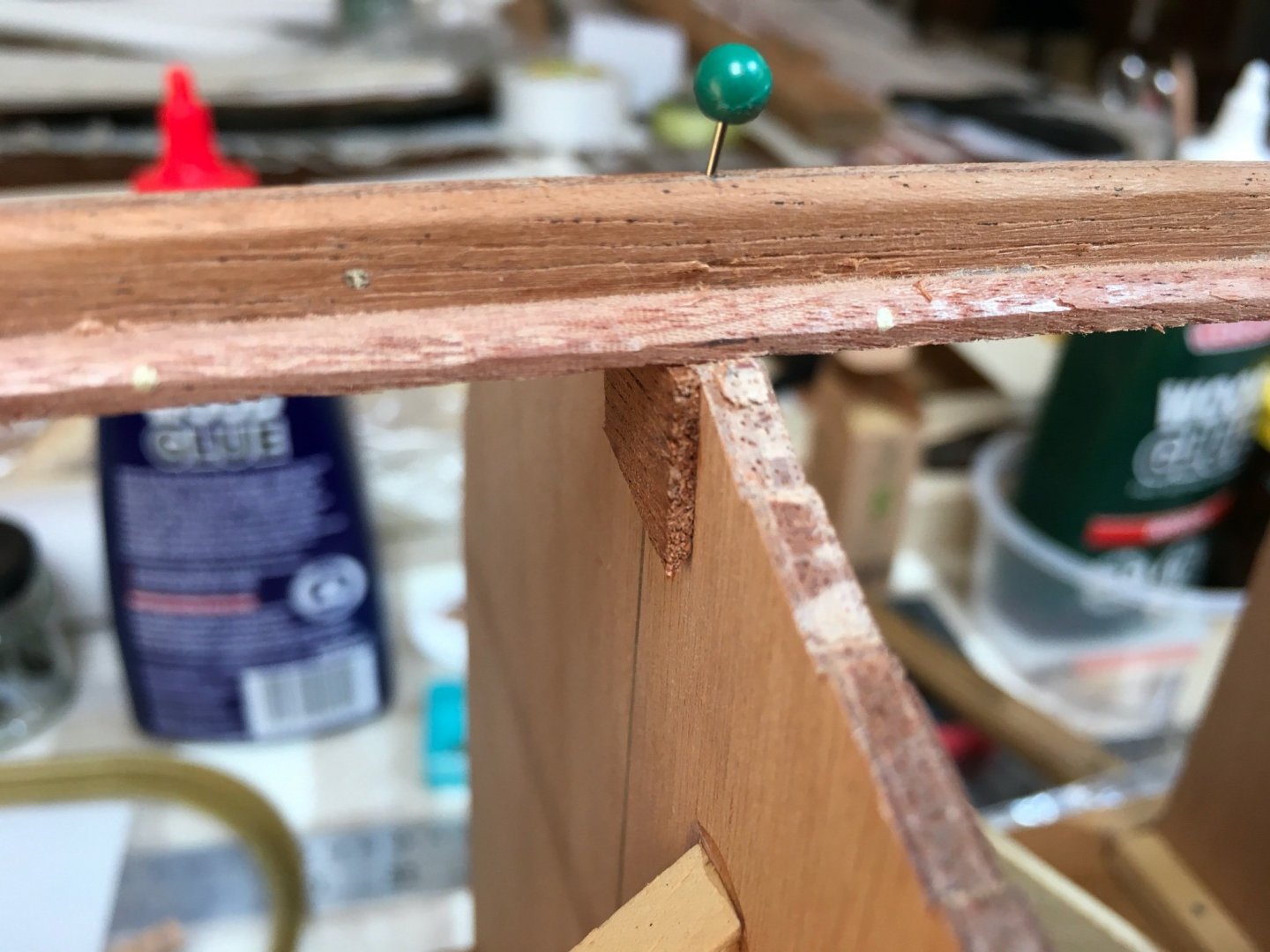
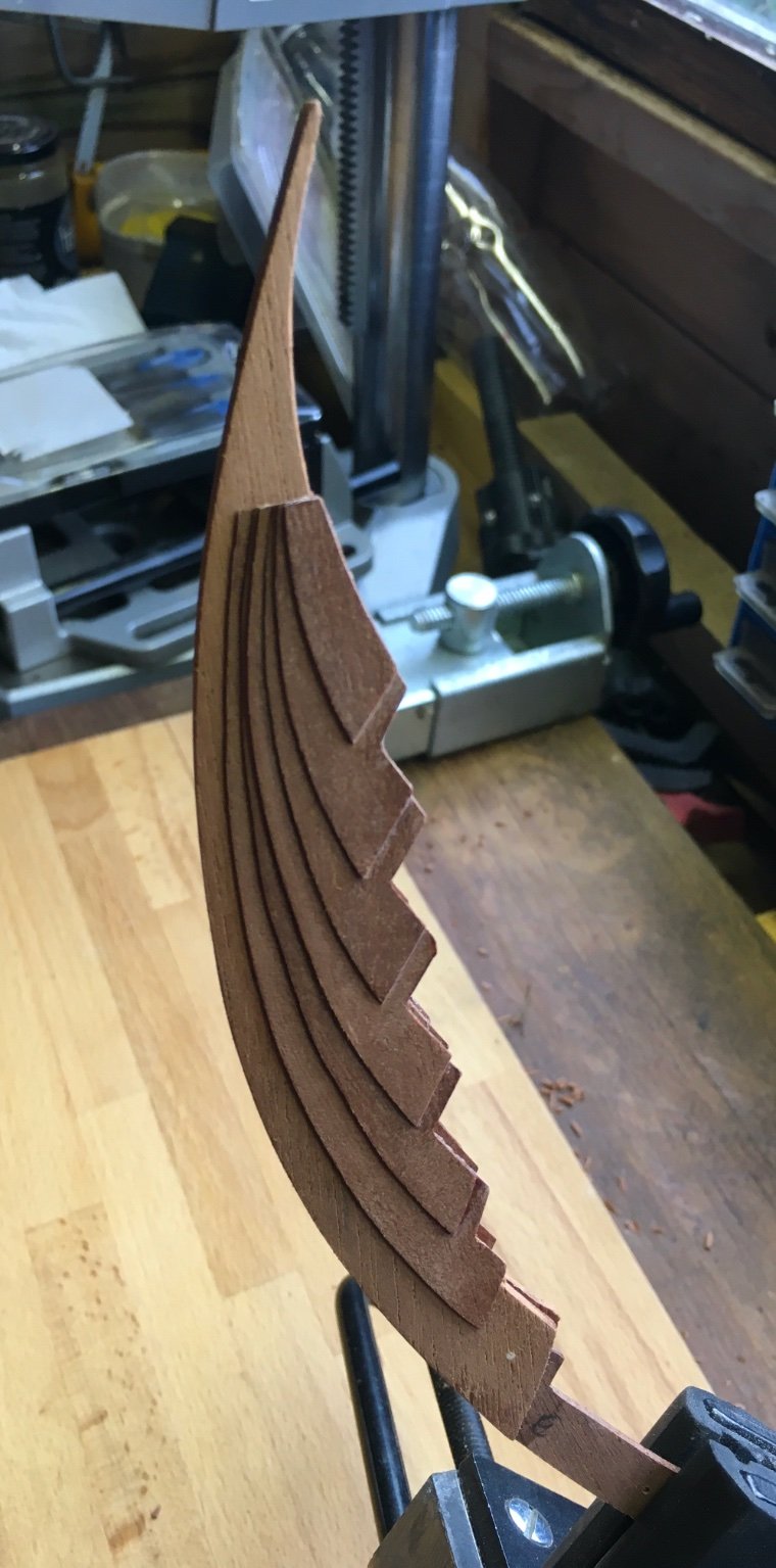
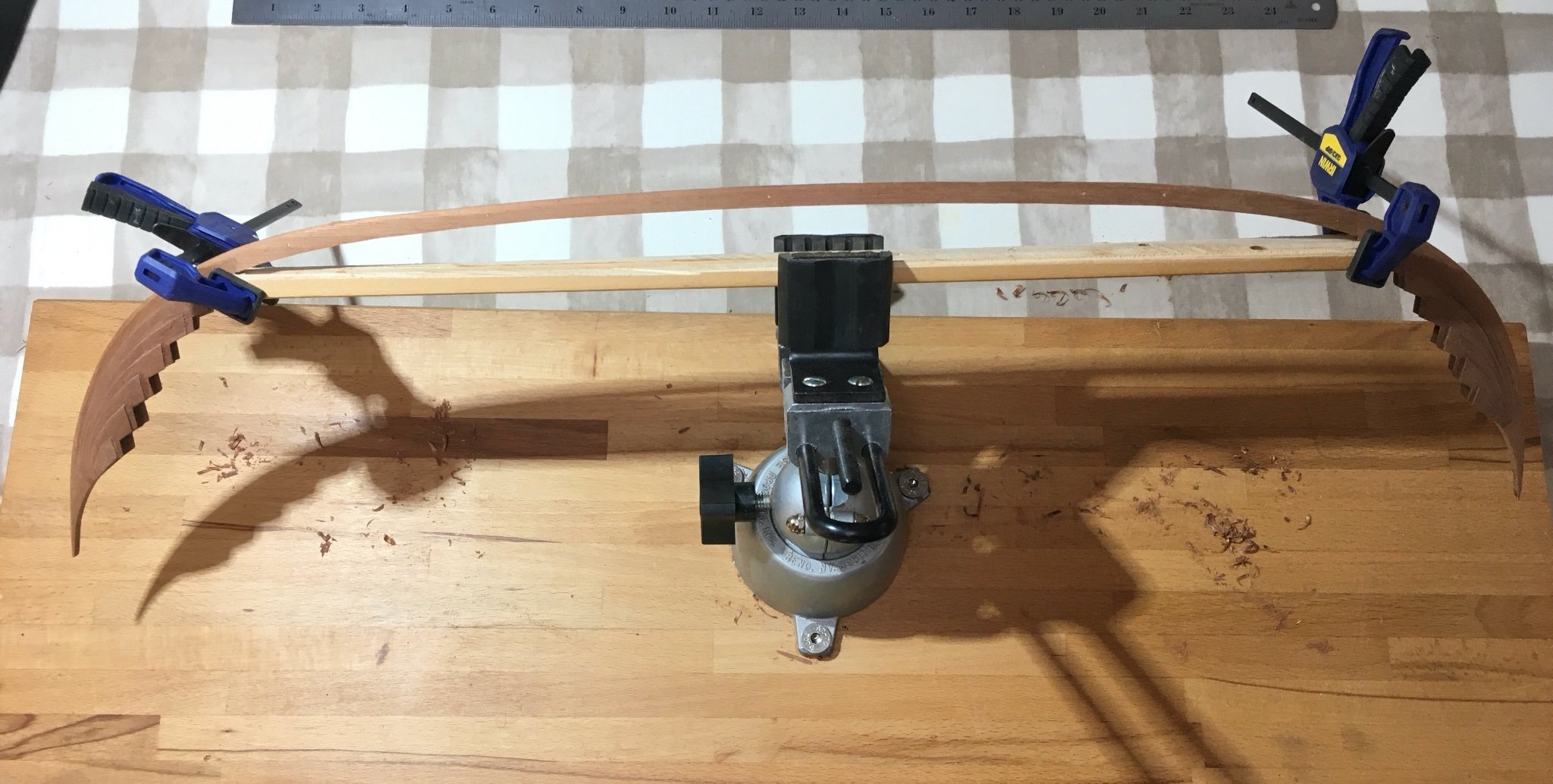
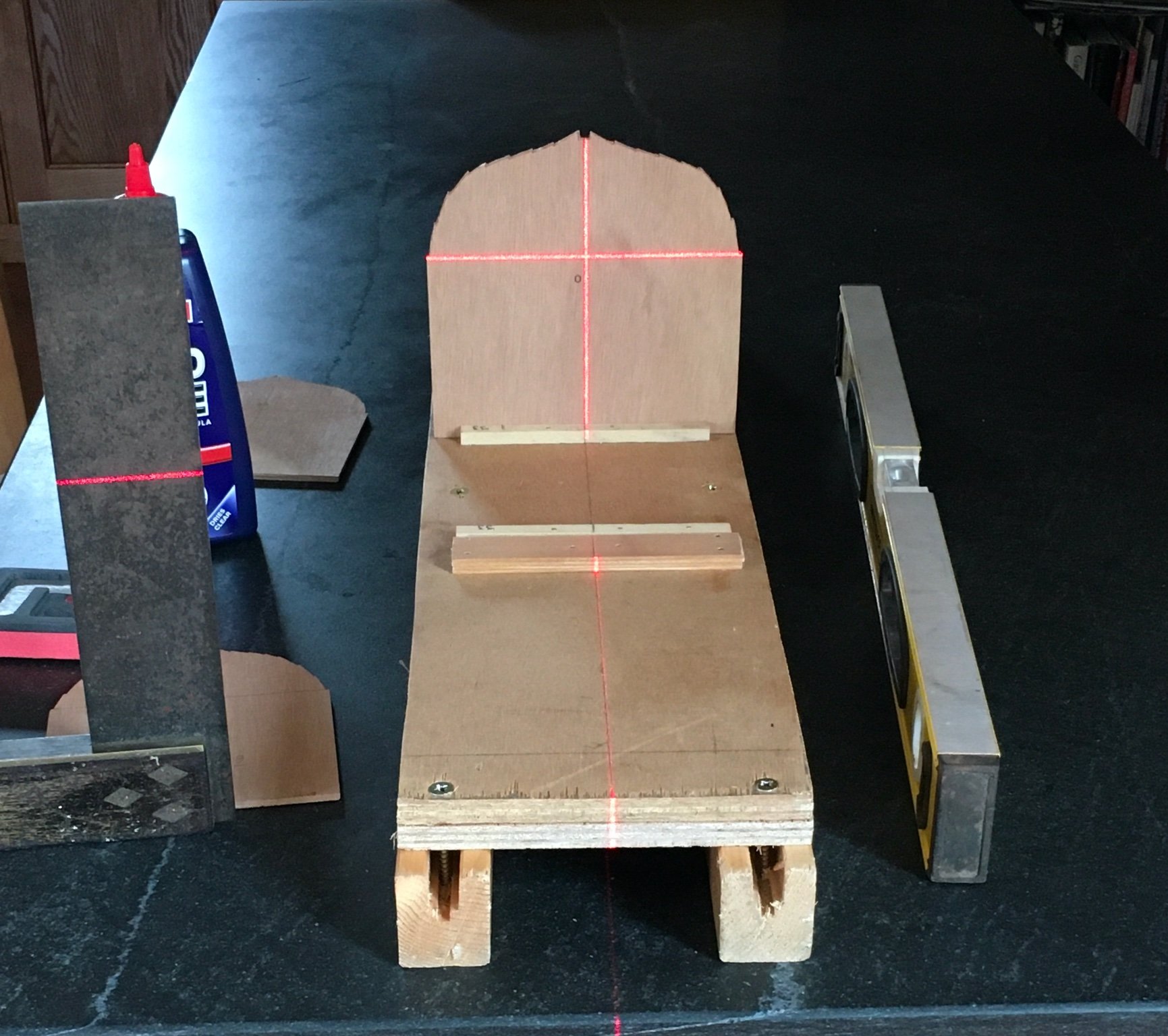
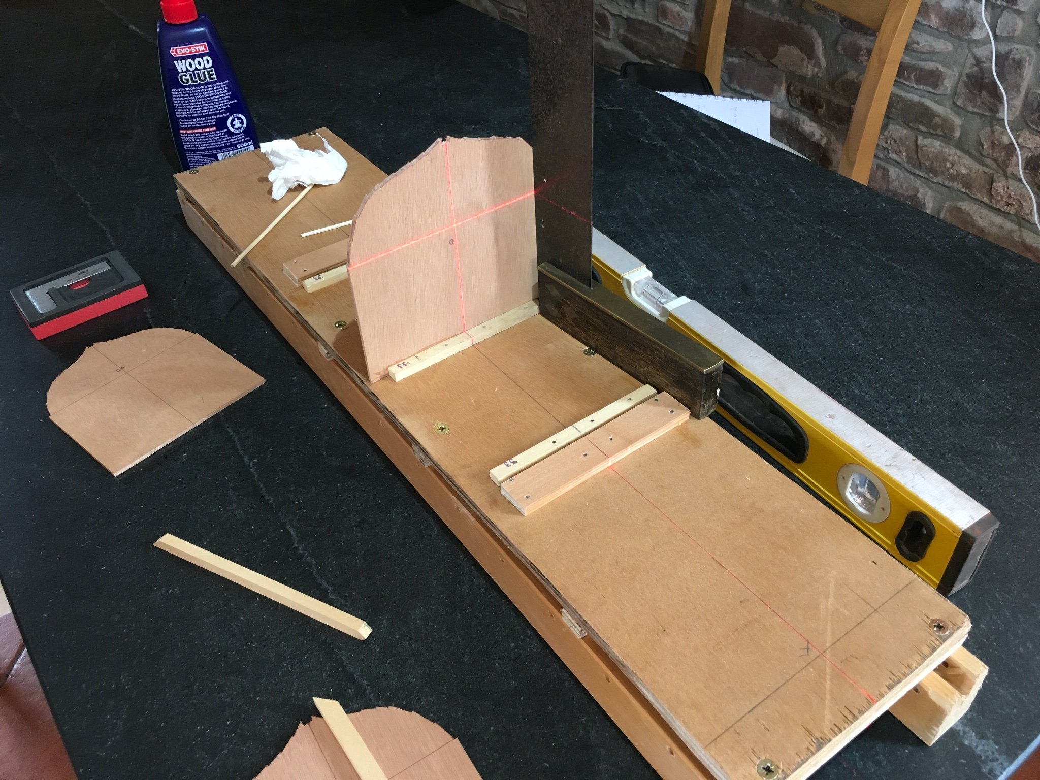
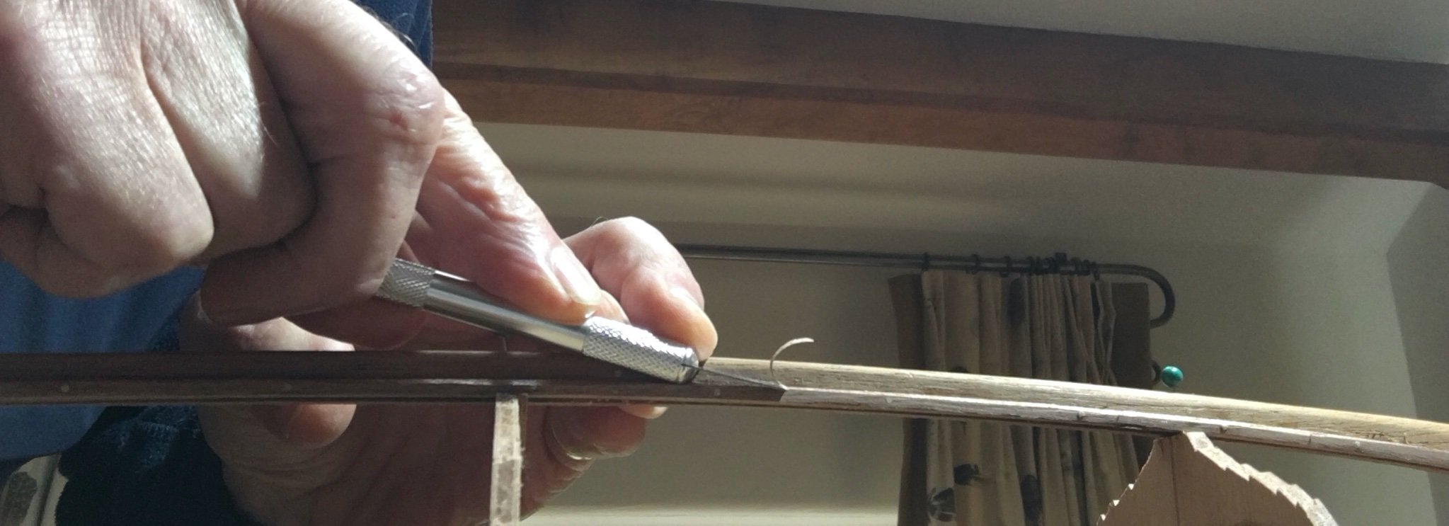
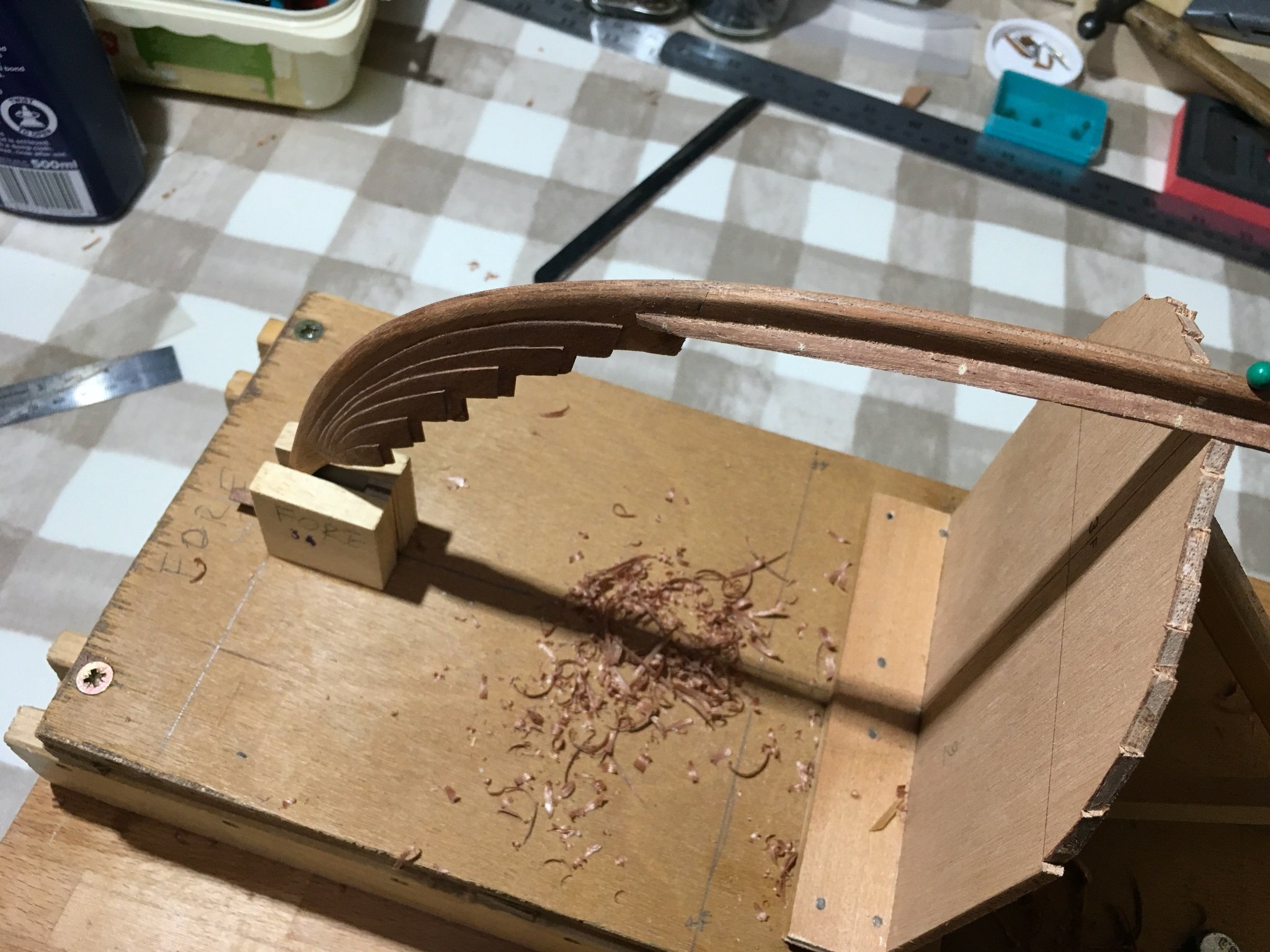
It's been a while since my last post. Having found time for small steps I never seemed to find time to keep this log up to date, hence this rather long 'catch-up'. The keel, stem and stern pieces The stem and stern and their composite side pieces were glued together and then the complete structures were carved and sanded to their final shape. Before After The shaped stem and stern were then reconnected to the keel, this time with glue as well as the previously drilled location pegs. Initial gluing (the masking tape on the Irwin clamp was being used to correct a minor degree of twist in the keel) Final setting under compression The entire assembly was then sanded and carved to give the final longitudinal profile of the ship and the cross-section profile of the keel. The entire structure wobbled horribly when being shaped so I rigged up a set of extended jaws which reduced the movement considerably and gave more rigidity (and confidence!). The keel and garboard rabbet The original keel was shaped from a single piece of oak to form a ledge onto which the garboard strake was fixed. The illustration below is from The Skuldelev Boats I, Crumlin-Pedersen & Olsen, 2002. The numbers and letters refer to the frame position at which the section was taken. I decided to reproduce this with a strip of 3x3mm mahogany pinned and glued about 4mm in from the lower keel edge, and to then profile this with abrasive sticks and chisels to approximate to the changing keel profile (in section). Before fitting the strip it had to be curved to match the curve of the keel. I decided the easiest way to do this was by immersion in boiling water but the length of the strips was larger than any basin I had and the bathtub uses too much water and cools very quickly. I constructed a container from some 40mm drainpipe and fittings I had left over from an earlier plumbing job. The strips were suspended on the end of a weighted length of cotton thread and the boiling water poured in and left for 10 minutes, then drained and repeated. The softened wood was then sandwiched between two thin laths and nailed in position on a length of wood on which I had previously drawn a profile of the keel. When removed from this extemporised jig the strips of wood held their curve and were then pinned to the side of the keel at a fixed height from the lowest edge of the keel. Once the position was confirmed as satisfactory the strip and pins were lifted, glue applied and then the structure left to set under pressure. The process was then repeated on the starboard side. This is an underside view of the keel assembly. Top layer is 3mm strip (at this stage just pinned), centre three layers are keel, and lowest layer 3mm strip, (pinned and glued). The planking jig This is relatively simple with only three formers set on the base with chocks to hold the down-curving stem and stern. Having set the base level I used a building laser to ensure the formers were set square as they were glued in position. They were given added rigidity with cross struts. Once the jig was built the complete keel assembly was aligned in it and, having checked the straightness of the keel, stem and stern, was pinned in place. The jig in turn was bolted to my work surface (using one of the inset M8 sockets) to give stability for the next operation. Having gone to the trouble of fixing the 3x3mm strips the next job was to remove much of them! I found a number 17 X-acto blade on a small handle the best way to achieve this. The work was done by eye against pencil marks which continued the line for the garboard strake from the planking jig. The work was slow but resulted in a satisfyingly Viking-like pile of shavings. The Vikings worked their keel by axe, as do those who have built the modern reconstructions of the Skuldelev wrecks. In passing the bamboo pins could be a nuisance since they constituted points of resistance in the timber (rather like knots). The nearly completed profile At this stage I need to think about my strategy for planking. I want to use 1.5mm sheet rather than the 0.8-1mm supplied so I plan to use the thinner sheet to cut and spline templates and then transfer those shapes to the thicker sheet. I know one issue I will have address is the mismatch between the plank thickness and the ‘rabbets’ at the stern and stem ends and I expect to have to thin the end sections, probably on the inside, to get a smooth transition. I will also experiment with plank to plank fixings, looking at the options for reproducing the rivets externally and roves internally. My initial calculations, based on the spacings recorded on the original wreck are that at least 1300 rivets were used! Both these topics have received a good airing in Louie da fly’s Winchelsea Nef Build Log which I belatedly, and now frequently, have consulted: https://modelshipworld.com/topic/29377-winchelsea-nef-1274-ad-175/ Antony
.thumb.jpg.a507df2aa80d33ca8b8396869526b529.jpg)
.thumb.jpg.0d7a866bf92c009d2880e4b9a7e8dbca.jpg)
.thumb.jpg.879dbf0d1f9e3e0b8ffea8c2ca65cbe1.jpg)

.thumb.jpg.d8c43208d3370c8692e655b2af497416.jpg)
.thumb.jpg.ae87858b29cae392e43e616512e28026.jpg)
.thumb.jpg.23612b7dbe66e02fee20fb4449bbbc08.jpg)
.thumb.jpg.71a5e209193227a73ac0796e72bea9d6.jpg)
.thumb.jpg.4efeab6a314b723ac71497f5554c986c.jpg)


.thumb.JPG.639997208556c9759bc0364f33da2b32.JPG)
.thumb.jpg.061fe55ecf34bceac7ca312b37d3fc89.jpg)
-
Hi Steven, Thanks for the supportive comments. I guess it’s a function of age but I seem to spend 45% of my time researching the next step (how was it done on the original), 50% of my time fretting about the next step (imagining everything which could go wrong), and then 5% of my time just getting on and doing it. The fact that generally the 5% goes OK suggests the other 95% is well spent! Antony
-
Hi Cathead, I still wonder if I should have tried carving the prow and stern from scratch! I’ve just been looking at your own Viking build; very impressive. Love the anchor; I’m already on the lookout for suitable stone and twigs. I’m fortunate in having access to the full archaeological reports of the Skuldelev finds so at least the wooden elements of wreck 3 (which is the best preserved) are available for reference. I’m undecided about rivets and will experiment but at the 1:20 scale using tiny (0.5mm diam, 6mm long) copper nails there is a chance it won’t look too much if patinated. Antony
-
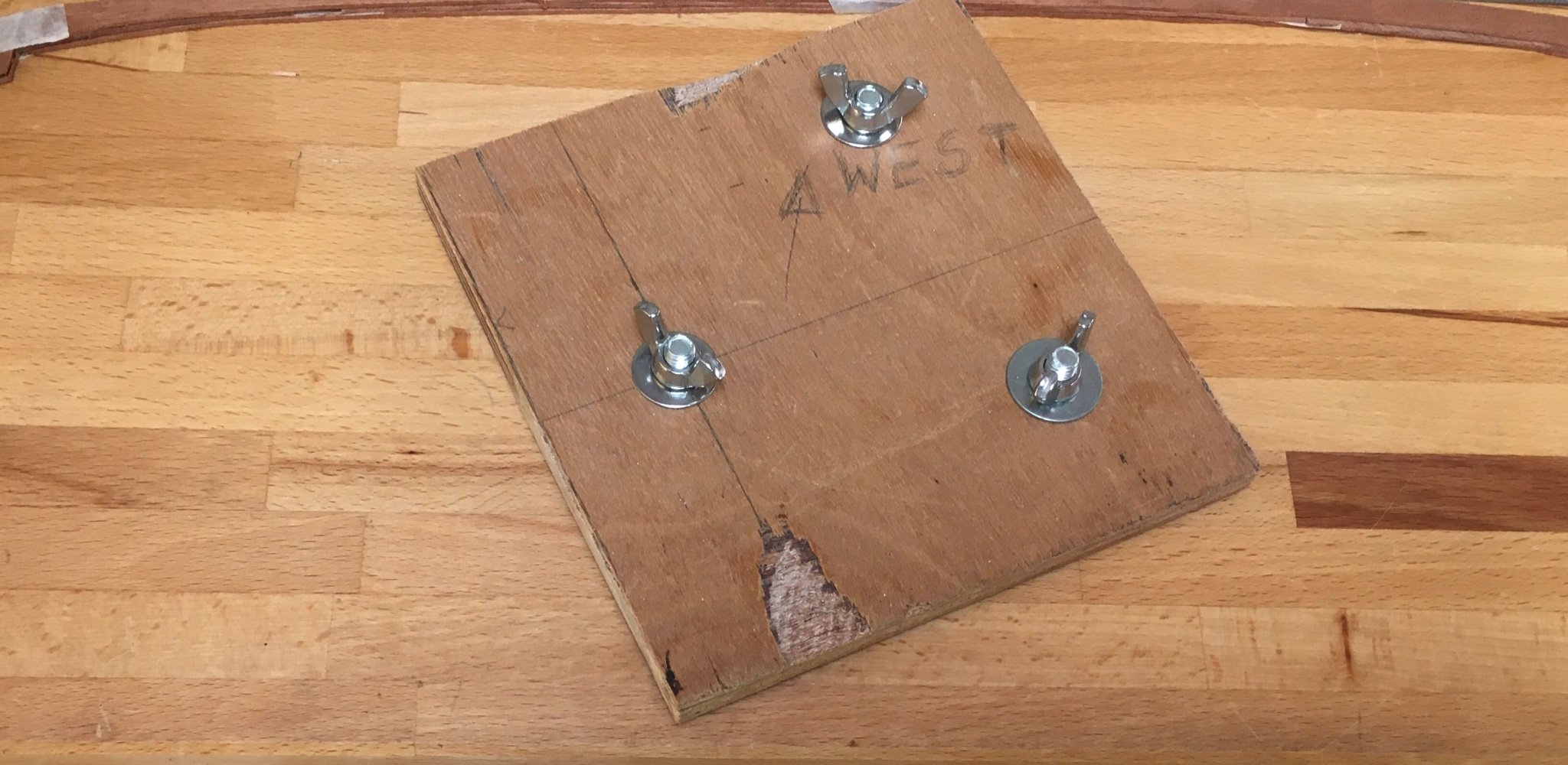
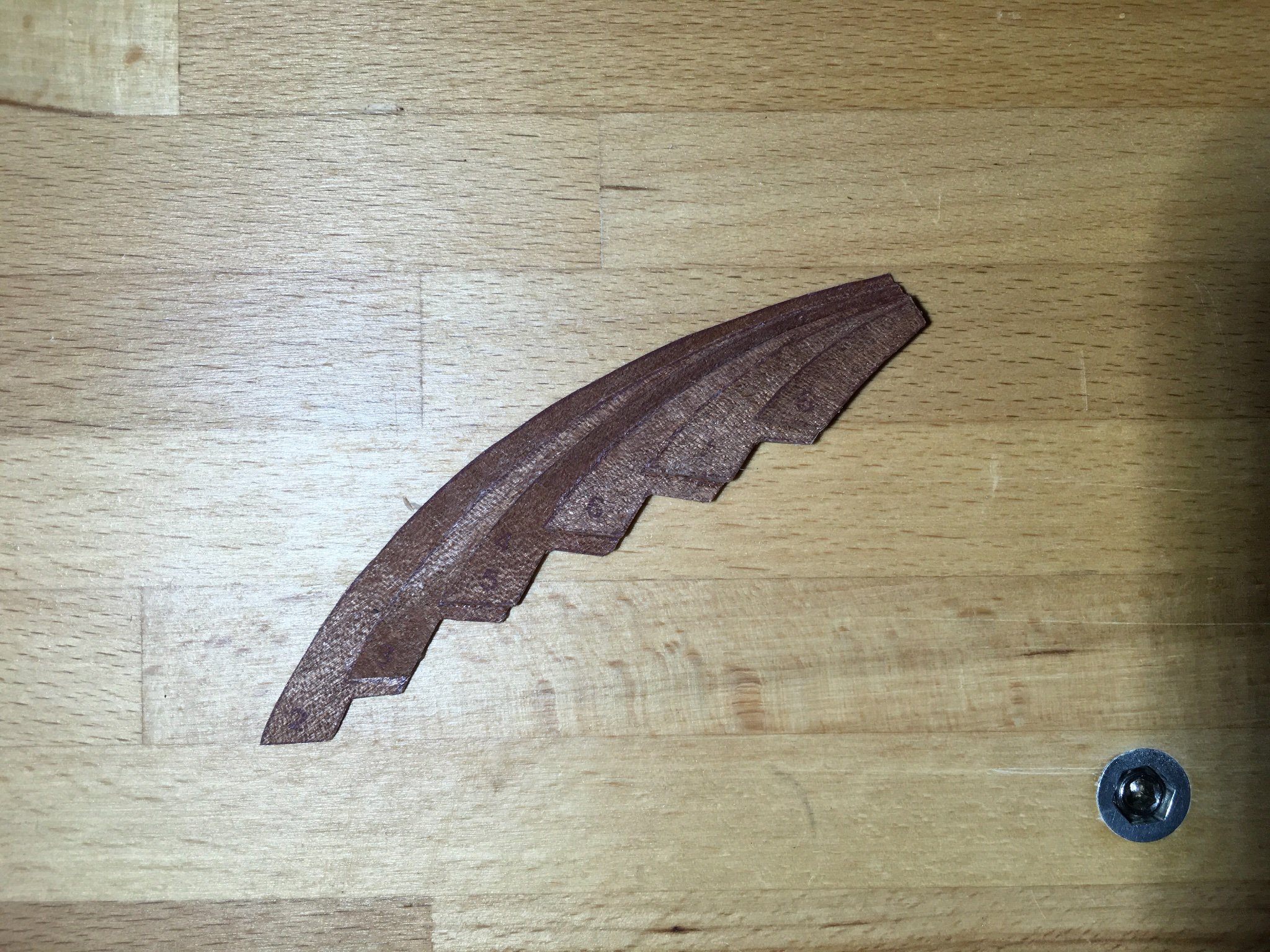
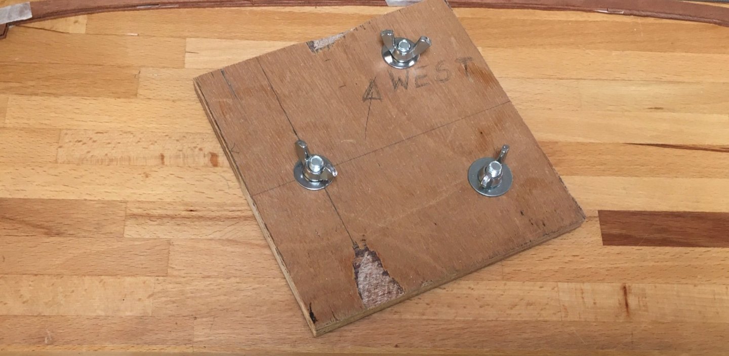
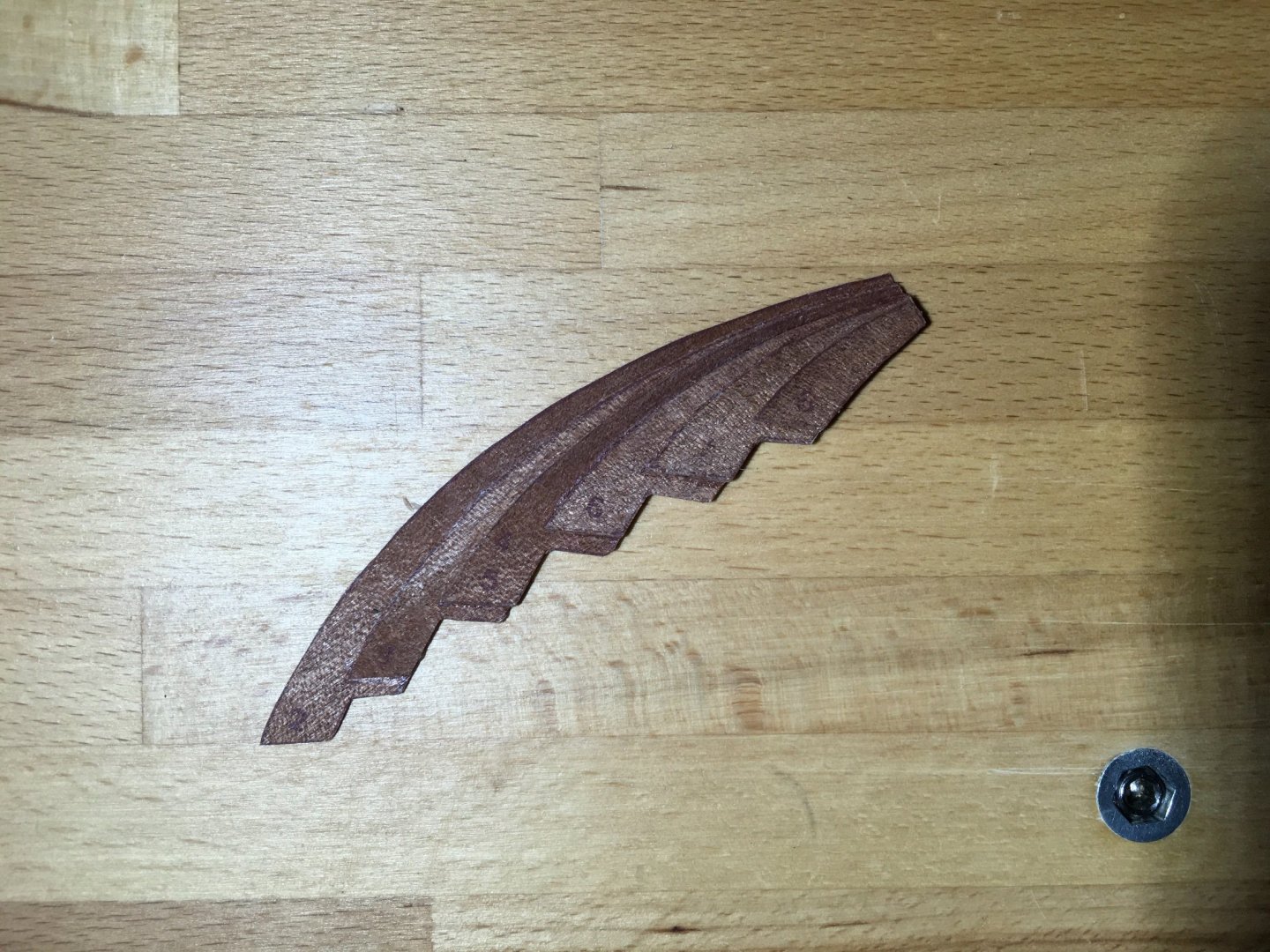
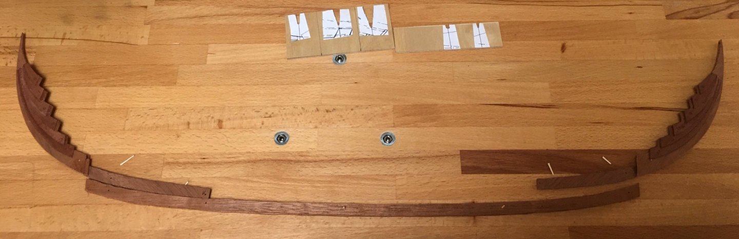
Feels like slow progress but such work as I’ve been able to do has been in ‘snatched’ moments from other tasks. The side pieces which give the ‘body’ to the stem and stern and also create the end rabbets for the strakes were built up with the layers sequentially glued in pairs (layer 1 with 2, 3 with 4 and 5 with 6 under compression). Working with ‘doublets’ in this way was easier than trying to align all 6 layers at once. The picture below shows one stage in a makeshift worktop clamp. The clamp is based on three M8 tapped inserts into which lengths of M8 screwed rod are inserted and the pressure applied by the wing nuts and washers. The inserts are normally filled by grub screws set level with the worktop surface to keep them free of dust. The pictures below show the final stack of 6 layers glued and clamped and then without clamps. The stepped construction will need sanding and carving to merge into the central element of both stem and stern. The core elements of the stem and stern were then fitted to the keel ‘sandwich’ and once correctly aligned at the joints held in place by tape then by bamboo pins. These were removable and their purpose was to ensure correct alignment when finally glued. I decided on this strategy since I figured that it would be quite cumbersome to carve the side pieces to the correct shape and profile, and to clean up the keel, if the entire stem/keel/stern assembly was glued and had to be handled as a single piece. The following pictures show the temporary assembly and then in its disassembled state. The sockets for the ‘bench clamp’ can also be seen. Viewed on edge the slot in the keel into which the tongue of the stem fits can be seen more easily. So now I have the main elements ready for gluing, shaping and connecting. The location pins should ensure the correct alignment when glued. In this picture the side pieces of the stem and stern are just laid in place, not glued. At the top are the templates I will use to ensure the prow and stern have the correct profiles in section when carved and sanded. Antony


.jpg.6347de87beb17ad0d064fa6a201ed487.jpg)
.jpg.9b16313a464e6982579bd793f54803e4.jpg)
.jpg.bf5d81c8f9bce3ff23c0ee1c56e0b6a1.jpg)
.jpg.6714ff60222801b1beb2bee551f44324.jpg)
.jpg.ef60ce243fda0a2c0a2147302af0b68a.jpg)
.jpg.3daafc22677ebebd66419666c212c284.jpg)


.jpg.660503d93b328c85ac86b8f2ff54d8c1.jpg)


.jpg.3c2dfd159566177069411062c0ef9348.jpg)


.JPG.97335226891b0d704d1a139cf7201f9c.JPG)
.jpg.93f35f2b7582149fee8c62e763620442.jpg)