ted99
-
Posts
234 -
Joined
-
Last visited
Content Type
Profiles
Forums
Gallery
Events
Everything posted by ted99
-
Fortunately, I was already using Measure 11 (because it was the colors I had on hand).
- 145 replies
-
- 2
-

-
- Enterprise
- Trumpeter
- (and 1 more)
-
So, Air Group 10 deployment 16 Oct 42 to 10 May 43 was the last to use F4F. Trumpeter provided F4F models, so I'll make it so.
- 145 replies
-
- 2
-
-
- Enterprise
- Trumpeter
- (and 1 more)
-
Stbd side "completed". Now going to turn the hull around on my workbench and start on Port side. Some touch up painting needed and going to paint the life rafts.

- 145 replies
-
- 6
-
-
- Enterprise
- Trumpeter
- (and 1 more)
-
Yes, those are the pictures I was going thru. They are very helpful. Thanks for the advice on color, as well.
- 145 replies
-
- 2
-
-
- Enterprise
- Trumpeter
- (and 1 more)
-
Yes, just the one grill above the forward bomb elevator. You can see on the earlier pictured piece of SS PE that two of these "grills" are provided in the MK1 kit. I also notice that the grill in the photo has a lot of "thickness", so I'm going to cut off the second provided grill and glue it to the top of the forward one to increase the thickness. Those pictures are very useful in finding out how the life rafts were deployed. The Trumpeter kit includes 16 of them, but there is no depiction of them in the plans. Most notably, it appears that the motor launch on the fantail platform, as shown in the Trumpeter plans, is removed and there are two stacks of life rafts in it's place. Other photos show them arrayed in various places on the sides of the Hanger deck. It looks like they were stuck wherever there was room. The photos are in B&W, so the raft color cannot be determined. Yellow? or Gray? Would they have been painted gray for wartime use?
- 145 replies
-
- 2
-
-
- Enterprise
- Trumpeter
- (and 1 more)
-
Aha--so those are bomb elevators. There are cutouts in the MK1 wooden deck for these elevators and two small pieces of decking to fit inside the U-shaped metal surrounds. The MK1photos show the forward PE part with a bend in the middle and the grilled part of the PE attached to the side of the Island. The grilled part was why I was calling them "vents". The MK1 photo does not show the after elevator having the grilled part on the Island, so I'll cut it off from the elevator hatch part. I see 6 "Barriers" marked as adjacent to arresting wire locations on the drawing, but only one piece of "wires" in the MK1 sheets. Plus, the kit wires are WAY longer than the width of the Flight Deck. The drawing seems to indicate that the barriers laid flat on the deck with the triangle-shaped pieces attached to the ends and were raised to a 90 deg position as needed. All in all, I think I'll just relegate those "wires" in the MK1 PE sheet to the "don't know" bin. I'll do this work after I've finished the detail work on the Stbd side of the Island and turn the model around on my bench to work on the Port side. This thing is so large that it's getting cumbersome to move it around.
- 145 replies
-
- 2
-
-
- Enterprise
- Trumpeter
- (and 1 more)
-
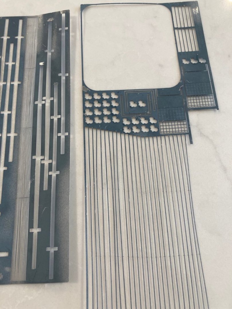
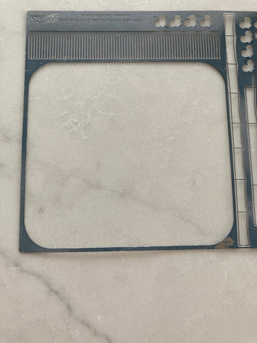
On the left sheet, the "wires" running lengthwise with 3 crossbars, but no bars at the ends. On the right sheet, the 2 "U"-shaped pieces in the middle. My calipers say they are the right size to be surrounds for the 2 vents to the right on the sheet. Problem is that the MK1 photos only show one of the the "vents" in place. It is on the forward, inboard side of the Island and is "folded" in the middle with the grill part flat on the island and the part with the "legs" flat on the flight deck. A small piece of wooden decking fits between the two legs--and there are 2 of these pieces of decking in the kit. There are also two cutouts in the flight deck wooden decking for both of these pieces, leading me to believe that there are supposed to be two of these vents; even though the kit photos only show one.
- 145 replies
-
- 1
-
-
- Enterprise
- Trumpeter
- (and 1 more)
-
I'm down to only two things I cannot find any photos for from MK1 PE in the SS "deck" details. One could be a catch barrier for a plane that didn't hook up and the other is a pair of "U"-shaped pieces. The catch barrier is way too wide to be deployed across the flight deck, without bends, plus I cannot find any means of attachment at the ends. I think the u-shaped pieces are edge detail for the gratings that fit next to the forward part of the Island/deck join. They are the right size for this, so I don't think they have anything to do with the catch barrier.
- 145 replies
-
- 2
-
-
- Enterprise
- Trumpeter
- (and 1 more)
-
Yes, that's the way it worked out. First wire just before aft elevator and last wire just before midships elevator. I was M-Division officer on Truxton, DLGN 35 (later CGN 35). We were mostly with Enterprise, except when we went North to be "North SAR". Since we didn't need to refuel, we ended up being plane guard for other Carriers, as well.
- 145 replies
-
- 1
-
-
- Enterprise
- Trumpeter
- (and 1 more)
-
Thanks for that. 9 sets of wires. Tabs used as I thought and the wires are reversed from the way I set them. Saw Gene at lunch and confirmed he was on the Ticonderoga and flew the F6F Hellcat. He describes how the Navy was desperate for pilots for all the new carriers that were to be commissioned and plucked him out of Princeton 4 months before graduation-- he had signed up for Naval Aviation and expected to be called up just after graduation. He completed training and a shake down cruise on another newly-commissioned carrier, but rotated out to Ticonderoga in time for the Okinawa invasion. Up until his 100th birthday, he was deadly on the putting green. Fantastic eye/hand co-ordination. I was on a ship that sometimes performed plane guard duty for carrier ops on my first Vietnam tour (ultimately did 3 more in-country). One of those times on Yankee Station we were with the Ticonderoga (lol). It had a half-assed angle deck, so that must have been a subsequent modification.
- 145 replies
-
- 1
-
-
- Enterprise
- Trumpeter
- (and 1 more)
-
So the 3 short dashes/crossbars are where the stand-offs go. I was postulating that the ears on the deck surrounds were part of the arresting mechanism mounts. That may be right, but the wires were on the other side of the ears than where I have them. Those crossbars/steel strips extend along the full length of the flight deck--standoffs on all of them? My error on F4F. He was on a sister ship to Enterprise, but I'm not going to ask him which one again. He was definitely flying a Hellcat.
-
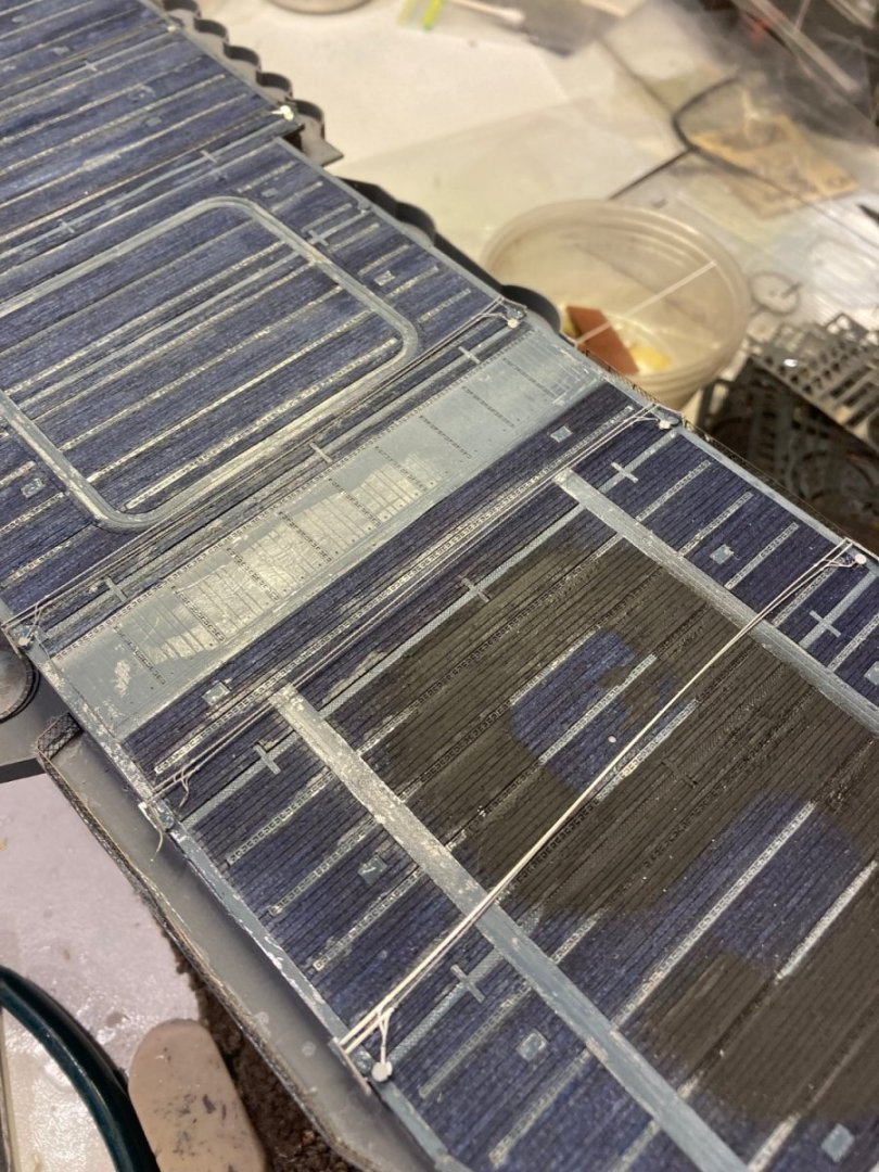
Checked with Gene and he confirmed that the arresting wires are fully at the stern. Makes sense that crash barriers would be around the Island. The Mk1 PE set has mesh as part of the PE set, but I have not yet found any pictures or diagram of how they are deployed. I asked Gene about the retractable hard barrier that is provided in the set and which is located just forward of the Island. He said it was always erected during flight operations. He told me a story about one time when he was waiting his turn for launch in his F4F and a landing plane got a wave-off. The pilot was slow to react and clipped the barrier with his landing gear crashing down on top of Gene's plane. Gene got out OK. Gene got the DFC for dropping a bomb straight down the stack of the then-largest BB in the IJN (Gene wasn't clear on the name, but this must have been after Musashi and Yamato were sunk), which resulted in it's sinking, in the Battle of Okinawa. Gene said that toward the end, when the air war was mostly confined to Kamakazi attacks, the F4F squadrons were repurposed to bombing and he did a lot of low-level runs skipping bombs into hillside caves. Picture shows the relocated arresting wires.

- 145 replies
-
- 4
-
-
- Enterprise
- Trumpeter
- (and 1 more)
-
Windows. They are 2.5X the length of the dashes. I was going through the "left over" pieces of deck (meaning the SS sheets) PE and found what is clearly the cover for the torpedo loading deck hatch. By "left over", I mean parts for which there were no pictures in the MK1 material and whose purpose is unclear. I've also been looking back at some of the small details for the flight deck on the instruction sheets and found things I missed the first time through--looking at the forest and missing some trees at the gross stage of construction. For instance, one small line on a drawing actually indicates the arresting wires are way up the deck starting just before the midships elevator and extending all alongside the Island, with one just after the "catch fence". That seems to be a lot more forward than I had imagined. I have a friend who was a WW II carrier pilot (he is 105) and I'll ask him about how things worked on WW II Carrier landings. This second look at the small insets on the plan pictures indicates that those pieces (described above) that I thought could have been the standoffs are really diagonal support posts for the "catch fence". It looks to me like there are no provided arresting wire standoffs--these would be VERY small details. I also finally saw a little inset of the torpedo loading hatch and the railing around it. You can see the railing still in the SS PE I pictured earlier--another mystery piece's location solved. I'm feeling really dumb.
- 145 replies
-
- 1
-
-
- Enterprise
- Trumpeter
- (and 1 more)
-
I'm afraid photo viewer is out of my wheelhouse. Looked through all of the PE sheets for the flight deck in the MK1 package and found only one set of "possibles" for the risers. There are "lots" of pieces of PE for which there are no pictures in the set and no idea where they fit. It's really an exercise of guessing.

- 145 replies
-
- 2
-
-
- Enterprise
- Trumpeter
- (and 1 more)
-
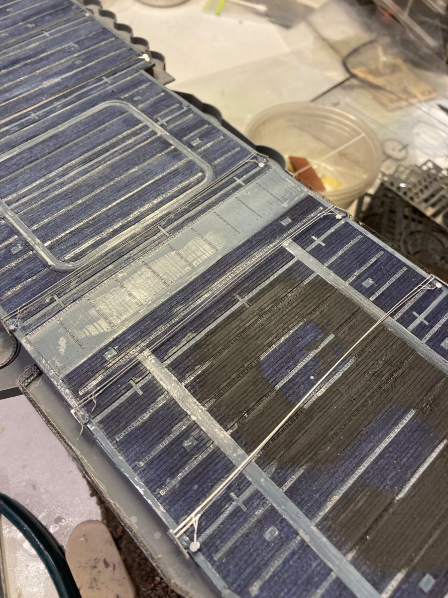
Well that was dumb. I was mounting the island and saw that I had put the wires on the foredeck, rather than aft. Gotta remove them and do it over. I've looked at the plans, but my eyes have not been able to make out the actual wire locations. Makes sense that there would be a riser in the middle to elevate the wires, but I haven't found what that would look like. The location of the wires, now that I see that they go at "the other end" from where I was fitting them, works a lot better as they are the correct length, now. But, it looks like one of the provided wires goes over the top of the aft elevator. I suppose there could have been one there that got broken down when the elevator was in use. I've inferred the locations of the wires from the location of the round fittings that look like they would have been part of the shock absorbing mechanism and "ears" on the deck surround plates. Never been on a carrier, so I have no experience of the mechanisms--just what I think would have been required while thinking as an engineer.
- 145 replies
-
- 3
-
-
- Enterprise
- Trumpeter
- (and 1 more)
-
The never-ending deck detail. Arresting wires. Guessed at them as no detail from MK1 and no on-line photos or drawings I could find. Probably in some book.
- 145 replies
-
- 6
-
-
- Enterprise
- Trumpeter
- (and 1 more)
-
Yes, but without a specific question to look for the answer, it's not as productive. What am I missing?
- 145 replies
-
- 2
-
-
- Enterprise
- Trumpeter
- (and 1 more)
-
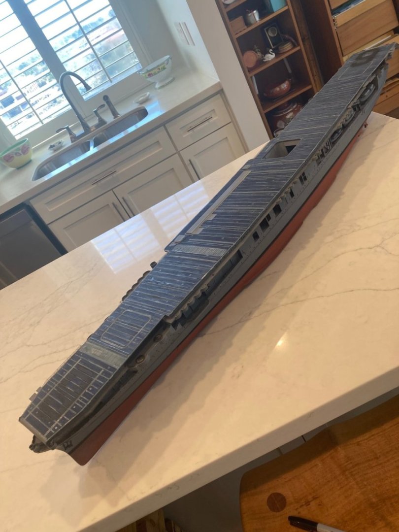
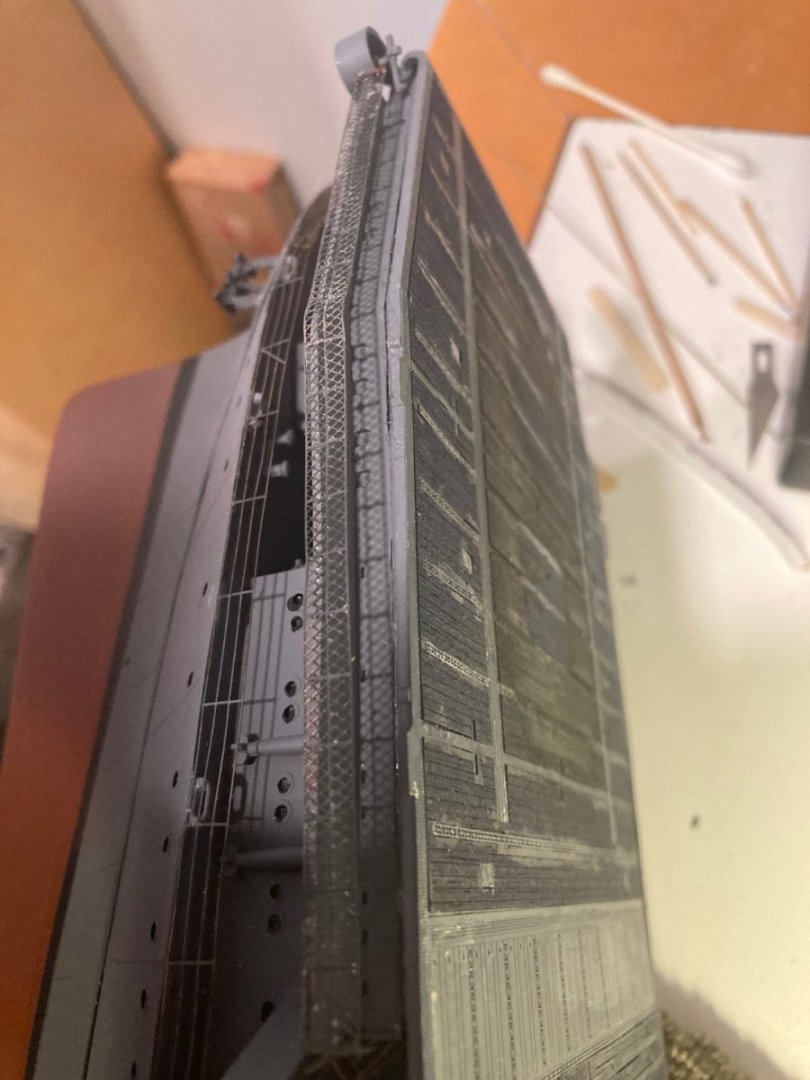
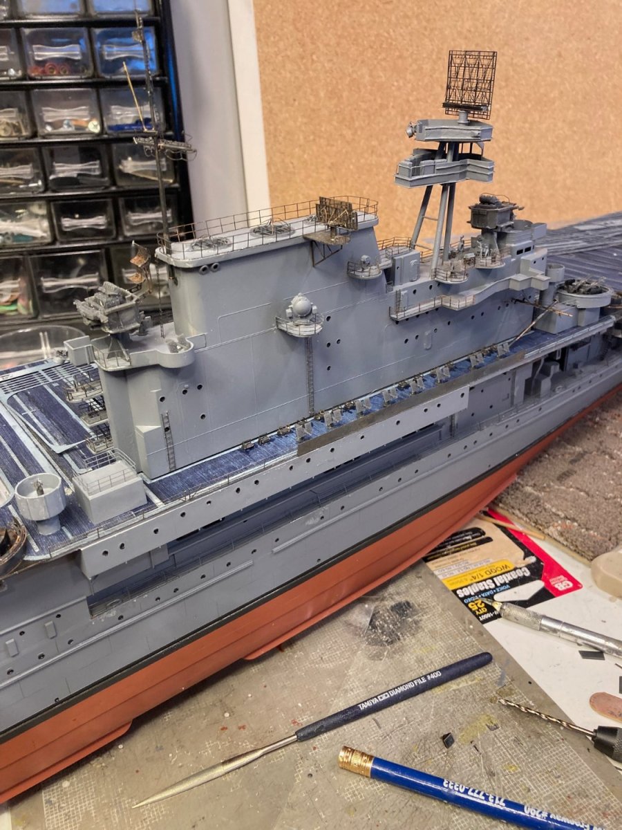
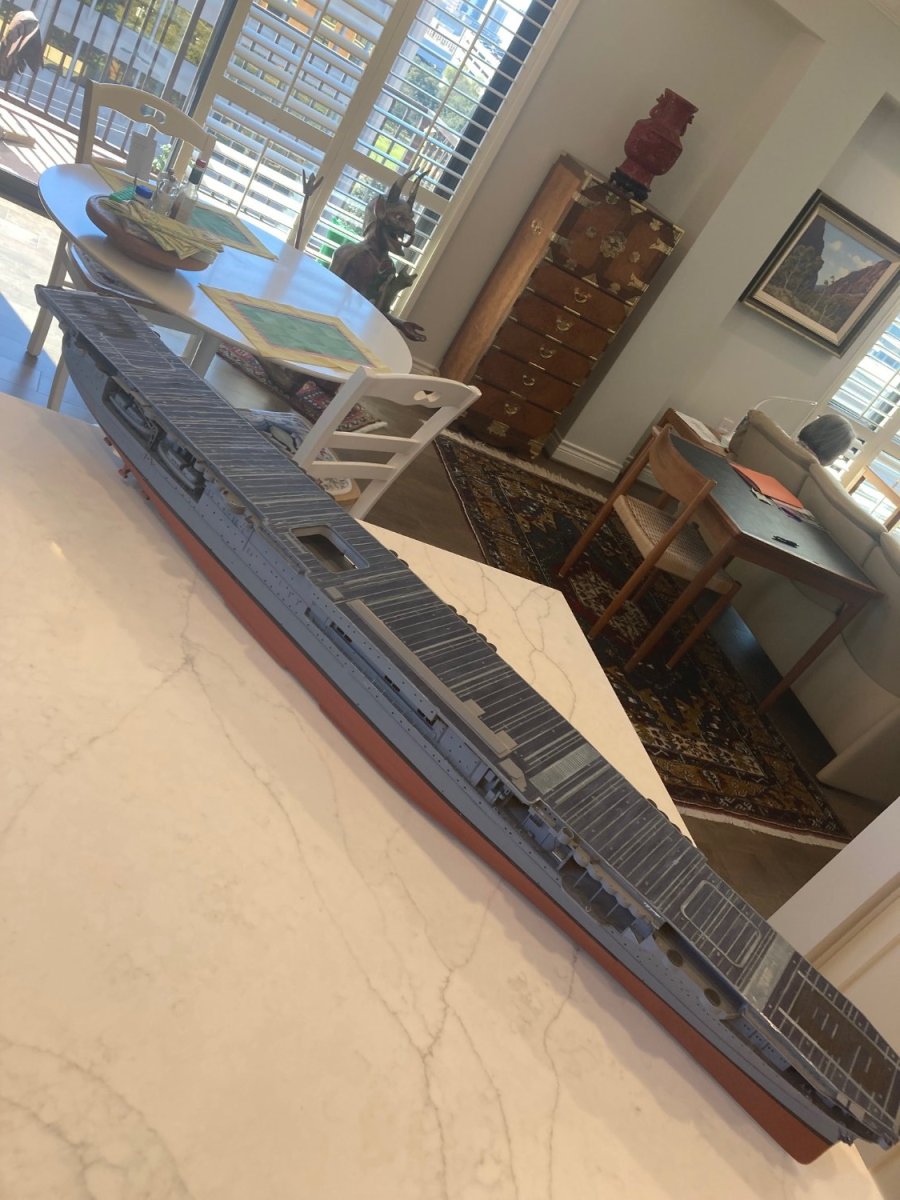
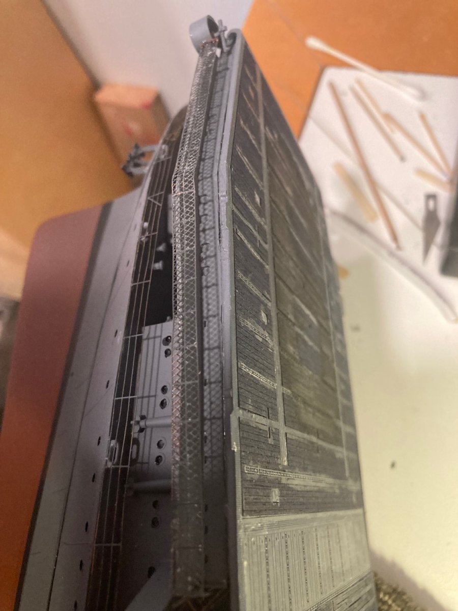
Hull deck join is completed, but not without a lot of difficulty. NOTE to future builders: The molded-in protrusions on the bottom of the flight deck do NOT line up with the relief points in the hull hanger deck sides. My recommendation is to dry fit the assembled flight deck to the assembled hull with hanger deck sides in place BEFORE doing any detail work on the hull or flight deck. 1. A LOT of the protrusions on the bottom of the flight deck and on the hanger deck sides will need to be trimmed to get a good join between the two. The good thing is that none of this trimming will be visible. It appears that there were mold changes as time went on and the two were not reconciled. If you do as I did and put on most of the detail before the hull and flight deck are joined, it will be a very delicate process to do all the trimming needed. You only need to dry fit the two until all of the interferences are found and then you can proceed to the details. Now that the two are joined, it appears that the details could be added after the join. It's just cumbersome to be moving the whole thing around on the bench. But, now that I've gotten to this stage, I think that if I were doing it again, I would complete the hull/deck join before doing the external details. Inside the hanger deck does need to be done first (lol). 2. There are two long platforms at the bow for AA guns and the plans have those platforms glued to the sides of the hanger deck. On my build, I could not get them to line up properly with the flight deck with them attached to the hanger deck sides, so I removed them and glued them to the flight deck, proper. I recommend that these parts not be glued to the hull until the dry fitting is done and you verify the fit of these AA gun platforms. 3. The flight deck will NOT fit properly if the kit-included plastic webbing is glued to the bottom of the elevators. These parts are way out of scale and are not visible, in any event, so I recommend that they not be glued on. The Pontos detail kit may have these in brass and may fit better, but they were not part of the MK1 detail set. It's time to place the Island and the other detail parts that I have held off until the join.

- 145 replies
-
- 7
-
-
- Enterprise
- Trumpeter
- (and 1 more)
-
I have suffered from my usual doldrums that appear when a project nears completion. The time has come to attach the flight deck and the hull, as I will need to invert the hull over the deck as part of the fitting and any additional details on the deck will prevent this. So far, the attachment has had it's share of difficulties. The molded-in reliefs in the interior hanger deck walls do not match up with the protrusions on the bottom of the flight deck. Lots of trial fitting, marking the interferences, and removing or cutting out the offending areas. Trial fit, find a new interference, remove and cut, retry. I've got them all now, so the gluing of the deck to the hull is starting. This also, will be an iterative process because of the need to weight each area of the deck as glue (E6000) sets, and this has to be a small section at a time. The good thing about this surgery is that it's all in areas that cannot be seen once the deck is attached. The kit has molded plastic girders beneath each elevator and ALL of them had to be removed to allow the deck to sit flush on the hanger deck walls. Unseen details, which were out of scale, in any event. I was afraid that I had erred in my assembly of the side walls, but the flight deck angles and reliefs line up perfectly with the angles in the walls, so it's a design error from Trumpeter at the mold stage.
- 145 replies
-
- 4
-
-
- Enterprise
- Trumpeter
- (and 1 more)
-
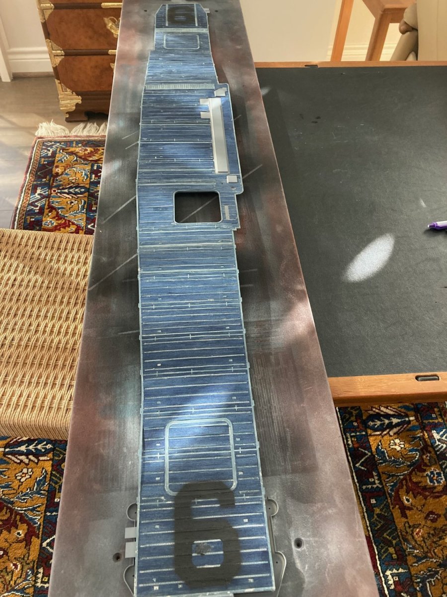
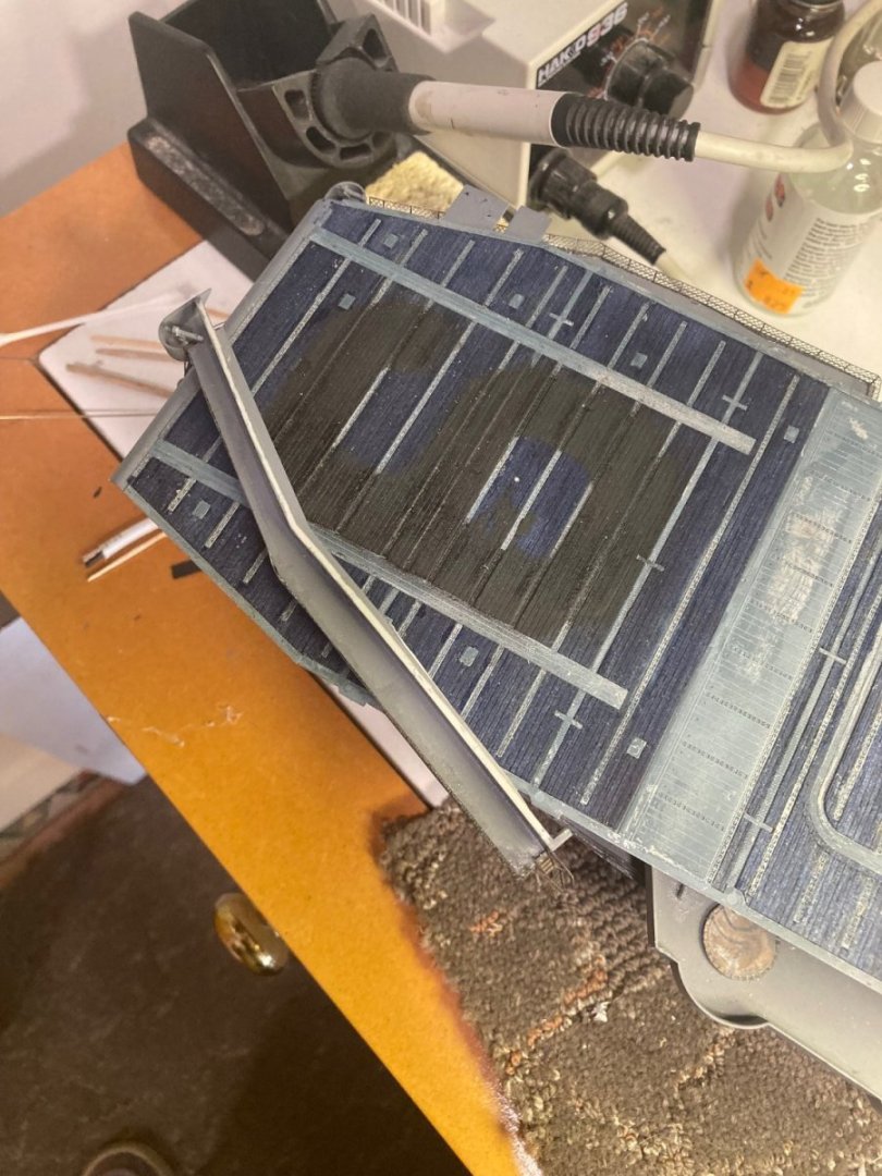
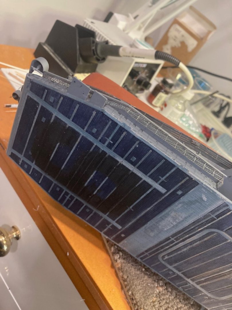
Back and mostly in the correct time zone. Time has come to put on the flight deck "6" numerals. Need to do this before adding all the arrestor wire details. Unfortunately, the Trumpeter decals are white, while all the pictures show black in wartime. No obvious sources of the correct size decals could be found, so it was stencil time. First applied one of the white decals to a piece of colored cardstock (to minimize water absorption and warping of the cardstock). Then cut out the white number and taped to the flight deck and did a flat black spray holding the can parallel to the flight deck to minimize fuzzy edges. If I had had any, a piece of paper with pressure contact adhesive would have been better. Results show that there is still a little fuzziness at the edges. The second number was better than the first by using multiple misting with dry time between, as compared to a single pass of the rattle can. Another suspension--travel to oldest son's for Holidays in CA. Thanks for the reading recommendations.

- 145 replies
-
- 10
-
-

-
- Enterprise
- Trumpeter
- (and 1 more)
-
^^^ Thanks. Reading your plans is the first thing I'm going to do when I get back.. I figured most, if not all, of my questions will be revealed there.
- 145 replies
-
- 2
-
-
- Enterprise
- Trumpeter
- (and 1 more)
-
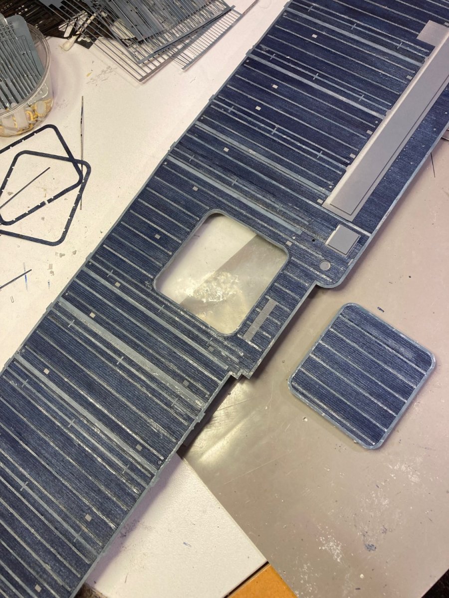
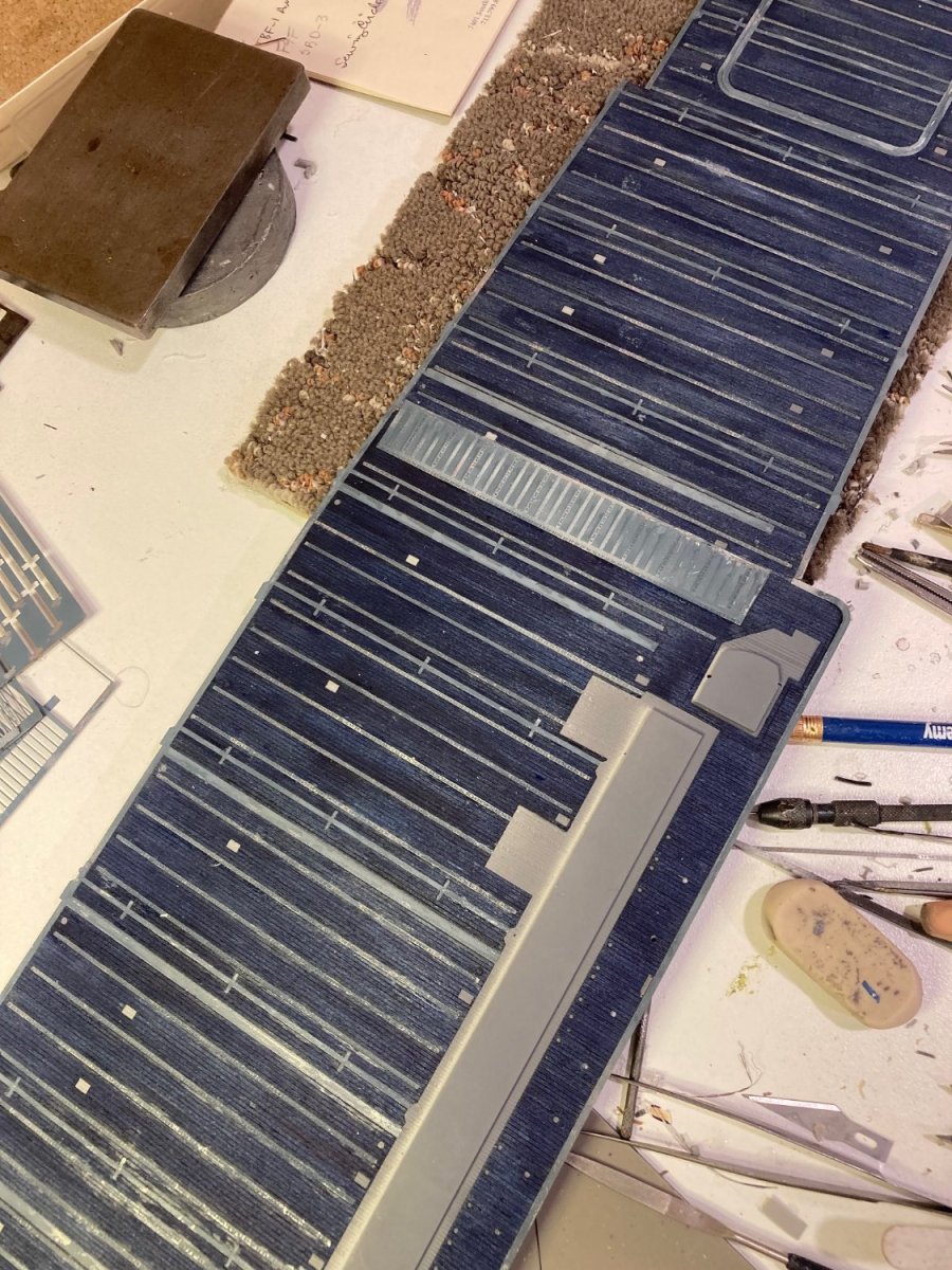
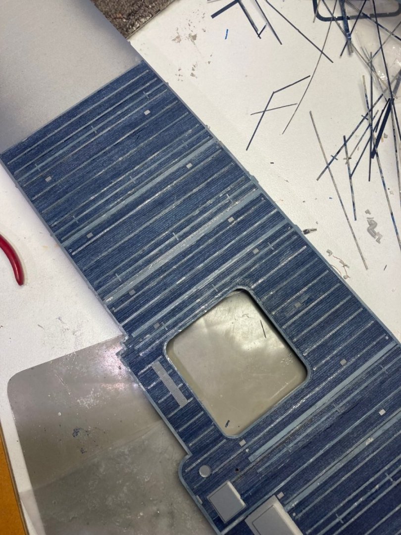
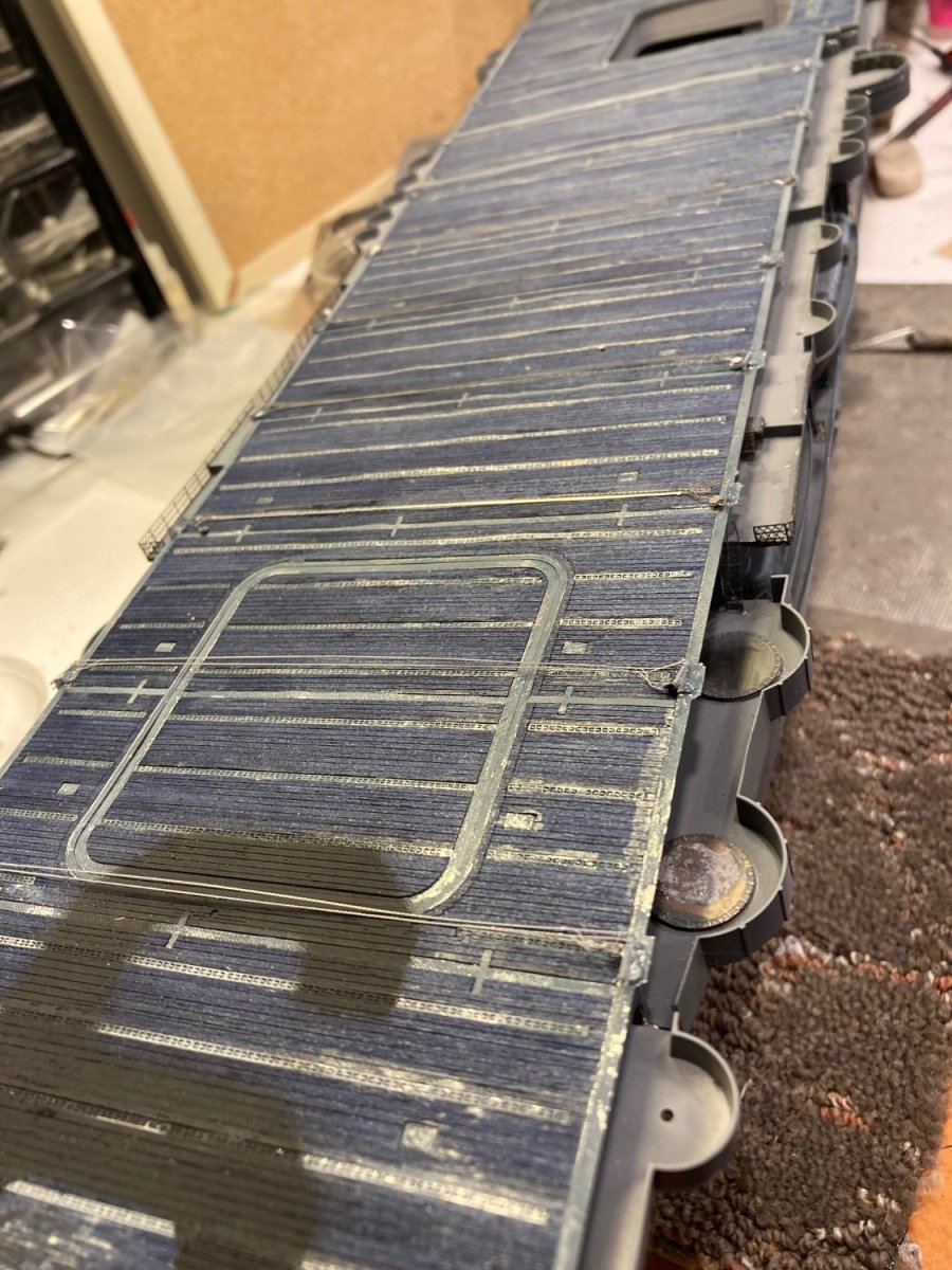
All of the decking now in place. The rectangular "windows" in the deck hold what appear to be hatches (unsure of this) which will be added next. Then I will try to figure out (from the VERY scanty detail provided by MK I) the anchors for the arresting wires. There is also a longer rectangular window in the decking adjacent to the mid elevator for which I cannot discover what goes there from the MK I "instructions" (and Trumpeter does not have it at all). It's looking like this kit cannot be completed without a lot of extra reference material--which I am loathe to acquire for a one-off purpose. From what I can see, so far, on the MidWest Models U-tube video of their CV-6 build; the Pontos detail set is vastly superior with vastly superior building instructions. Appears to be well worth the extra cost. I almost feel like waiting for that build to catch up with where I am so that I can see what some of these things actually are. In looking forward, I think I will need to attach the deck to the hull very shortly. It appears that the best way will be to place the deck upside down on a flat surface and put the hull in place (also upside down) and glue with medium CA. This means that I must have the deck surface all at the same level, so some details (like the arresting wires and catch nets) will be attached after getting the deck in place and putting the island in place. This model is so long that it's really cumbersome working on details near the forward or aft ends. About to leave for a 3-wk river boat "Christmas Markets" trip, so will be taking a break. I wish the MidWest Model CV-6 build had spent a little less time on painting and weathering so that it was closer to my progress. I really need to crib from it, despite the fact that he is using the Pontos detail set.


- 145 replies
-
- 6
-
-
- Enterprise
- Trumpeter
- (and 1 more)
-
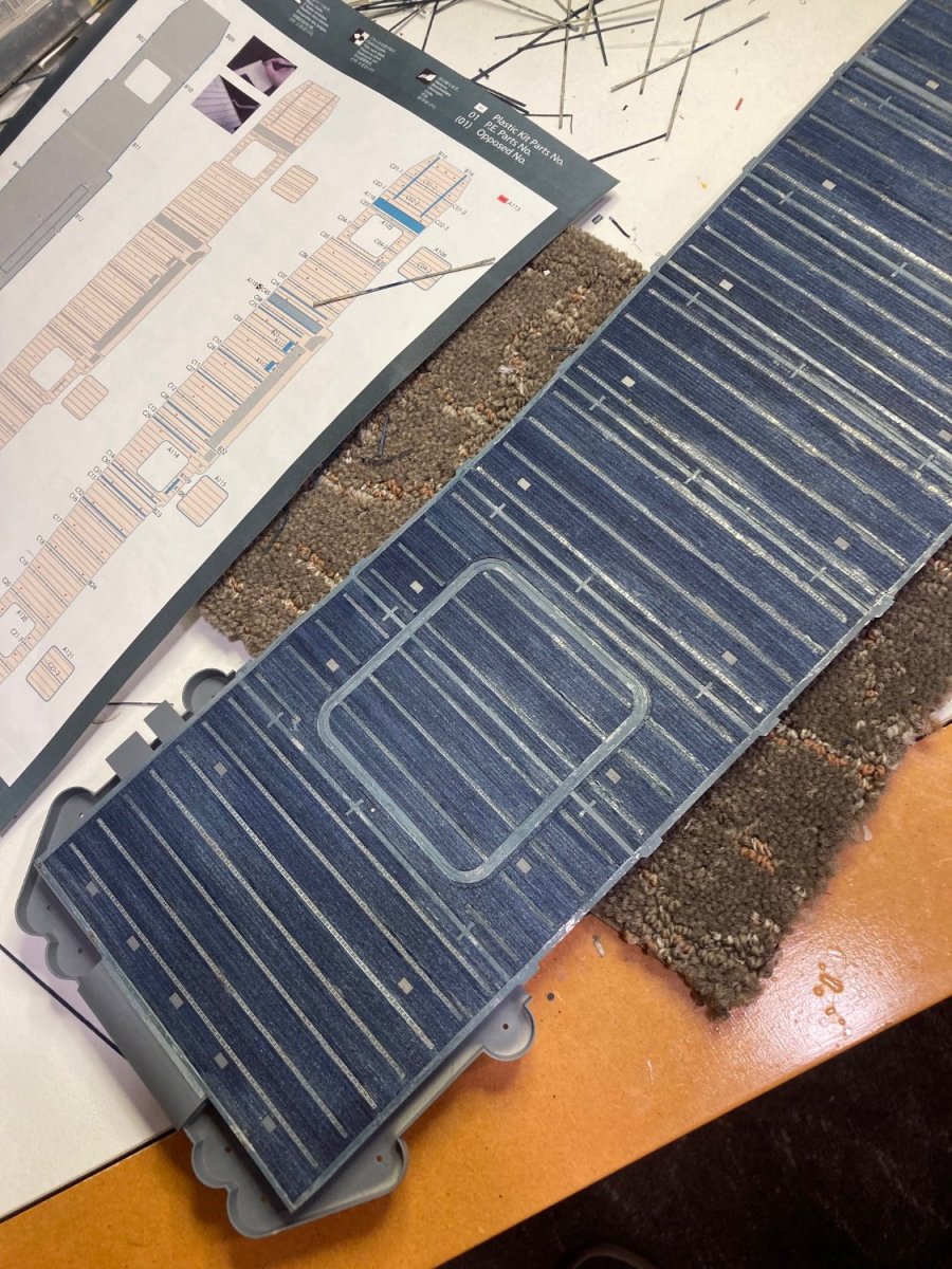
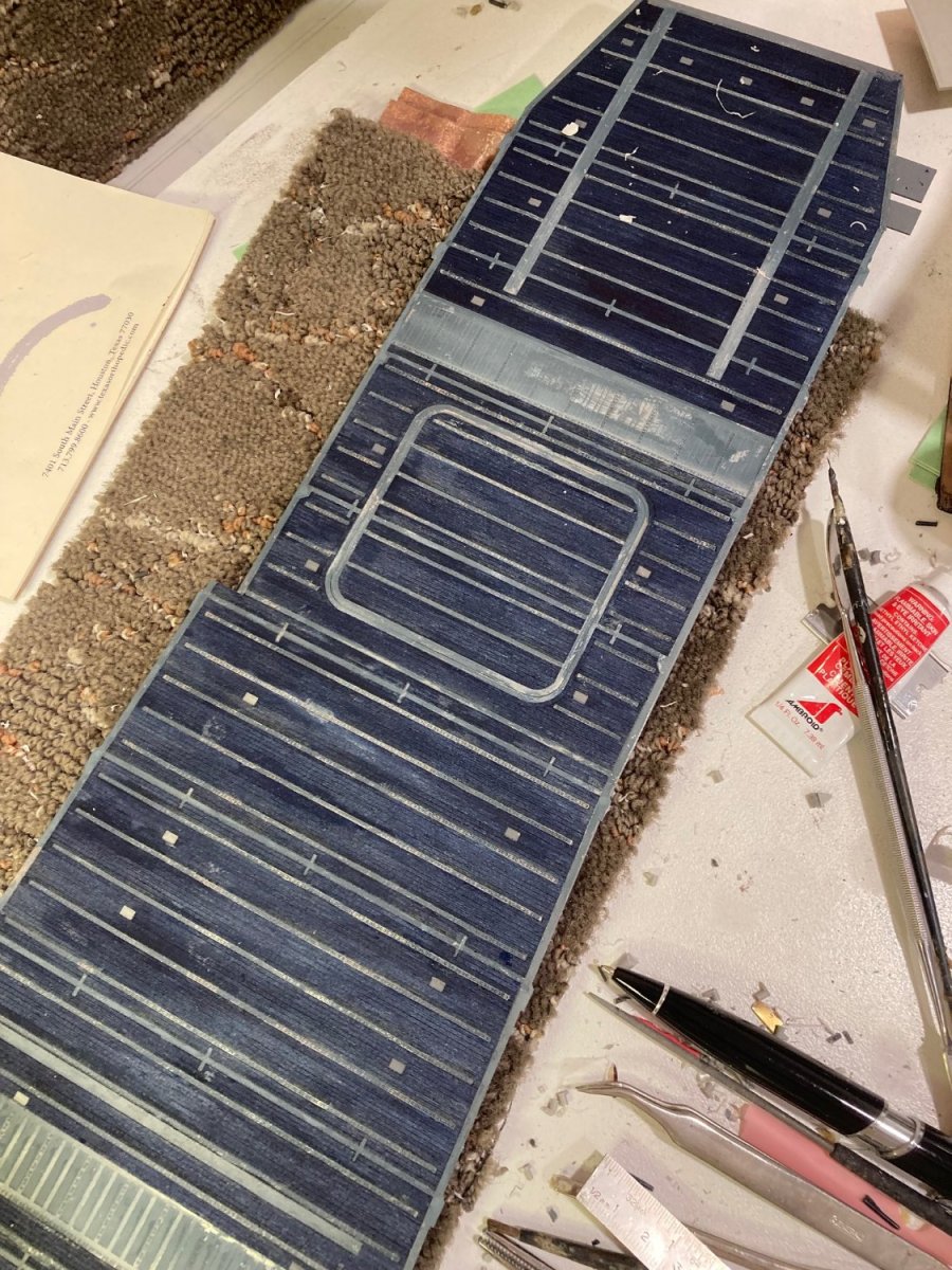
Next section aft of the island in place. Used the aft elevator as the "anchor" placement for the decking. As expected, I had to add a single board to make up for the board I had to take out of the first section forward of the island, because the place I had indexed to for the center section of decking was "one board" too far aft. This says to me that if I had started with either the midships elevator piece, or the aft elevator piece as the first piece of decking installed, all the subsequent deck pieces would have gone into place exactly as designed. I'm modeling with the midships elevator in the lowered position. Hence, the missing mid elevator platform. Construction techniques as before. So far, the PE pieces around the perimeter of the decking have gone into place as designed.
- 145 replies
-
- 7
-
-
- Enterprise
- Trumpeter
- (and 1 more)
-
^^^Is there a way to correct this? Haven't looked at the kit, except to verify that the wood deck fit.
- 145 replies
-
- 2
-
-
- Enterprise
- Trumpeter
- (and 1 more)


.jpg.9d59fa4e1dae1345528e24585fc9a1a2.jpg)