Andrew Egan
-
Posts
23 -
Joined
-
Last visited
Content Type
Profiles
Forums
Gallery
Events
Everything posted by Andrew Egan
-
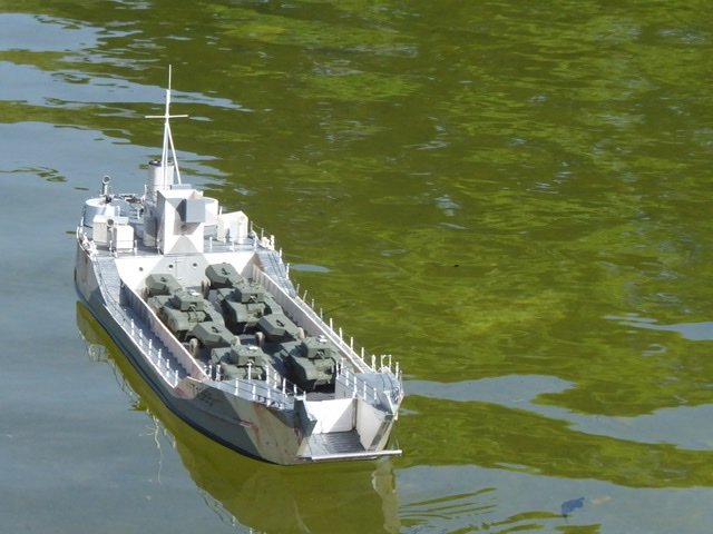
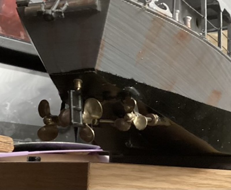
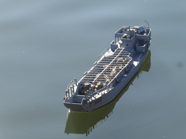
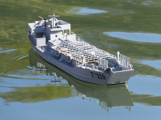
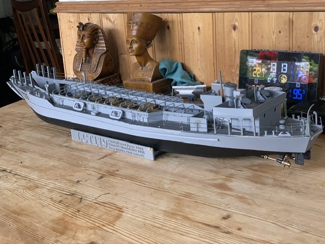
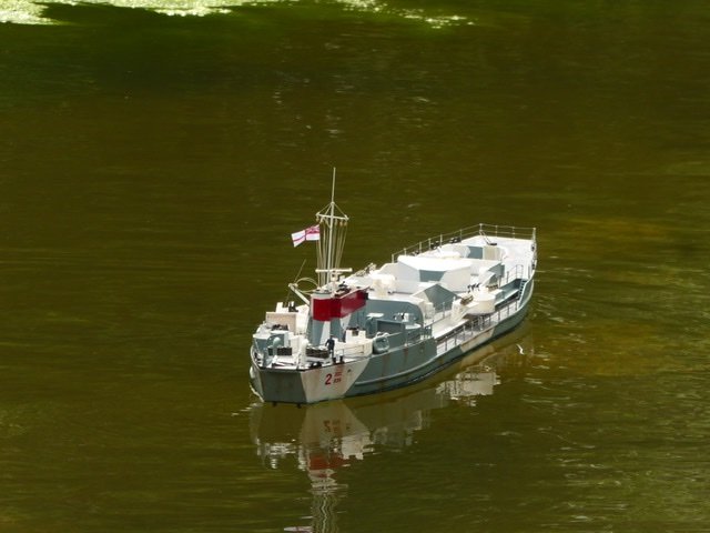
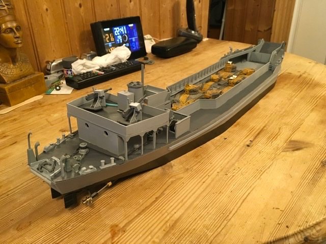
Not quite, a little weathering and minor touches to be done. Tanks are 2 Honeys (Stuarts), 2 Matildas, 3 Valentines. Then there is damage to repair from sailing and accidents. Now she has gained a few scars, and some parts need replacing. Added the bridge across the ramp entrance, damaged to bow so repairs, anchor davit knocked off so replacing. decided to alter drive an steering to be more realistic, single rudder and all three screws turning the same way
.JPG.686f78e560a09463a7a3540314cae505.JPG)
-
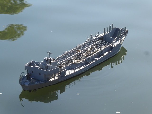
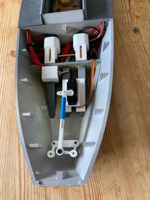
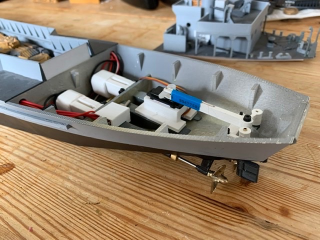
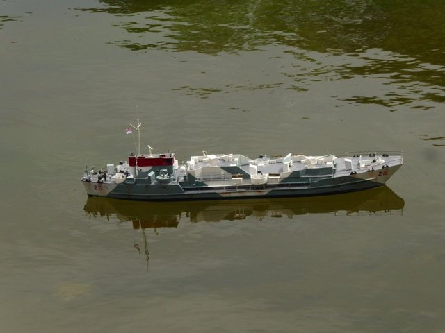
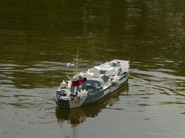
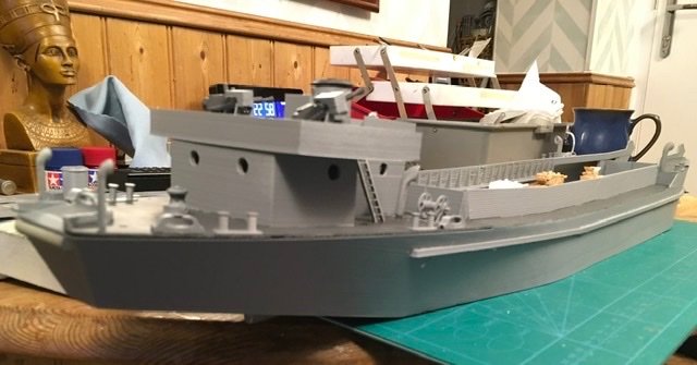
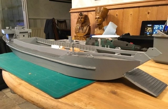
I lost this thread and only found it again recently. The story of LCT119 model has moved on quite a way. Her maiden voyage with two motors was not bad but she was under propped. A general change round of props between the landing craft found some that suited the motors better. The single motor mounts were scrapped, which created enough space to fit three motors which proved to be much better. Meanwhile I added detail, stanchions were bought from Dean Marine but all other detail was designed by me. Very recently I found a text that asserted LCT(2) only had one rudder, mine had two. Some work has now been done to give her a single rudder and to make all props turn the same way, like the original. The tarpaulin ribs are 3D printed with a 0.5mm cross section and really add something to this little boat

-
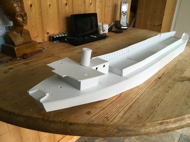
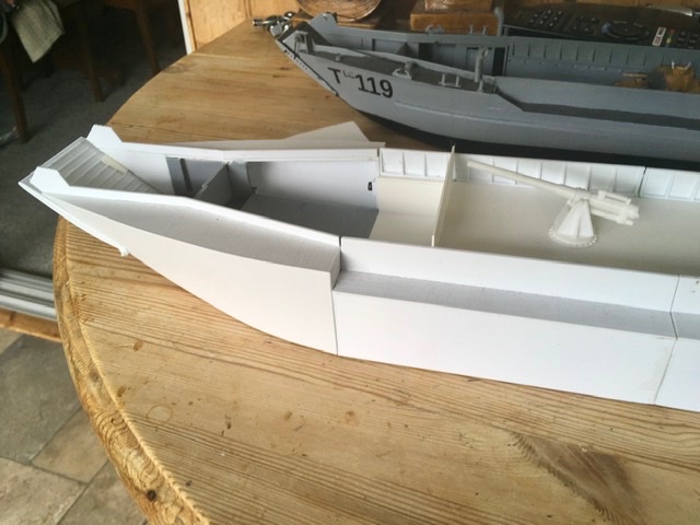
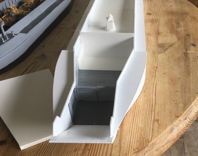
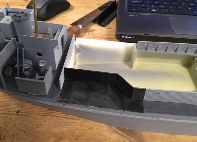
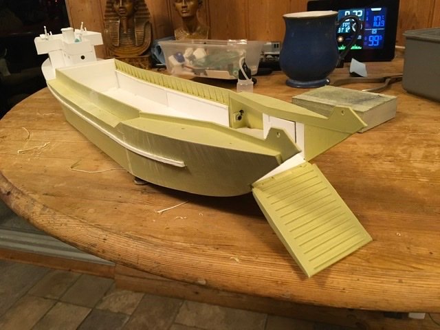
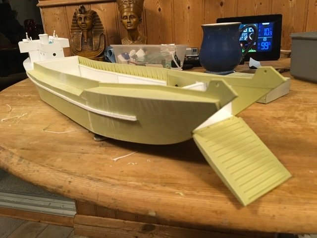
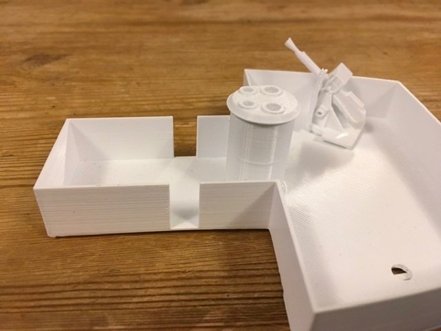
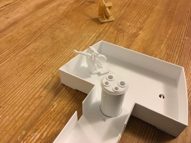
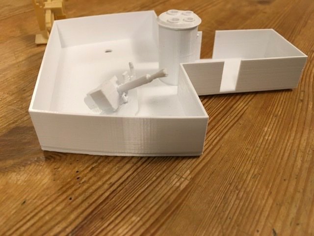
I have already posted pics of LCG939 (now tested and fully operational) but there was a previous series of LCG based on the LCT3 hull. These were hurriedly and cheaply converted in early 1943 to support Operation Husky, the invasion of Sicily. The conversion looked something like this, a huge open well forward of the gun deck. LCG15 and 16 sailed from Belfast via Holyhead, bound for Falmouth when a violent storm caught them at sea. Refused entry into Fishguard and Milford Haven, both ships were overwhelmed and sank with only three survivors. The remaining ships were decked right to the bow and gave good service. I think a short deck conversion would be an interesting project but it is far from certain where the forward bulkhead should be. Current evidence points to this location
- 34 replies
-
- 11
-

-
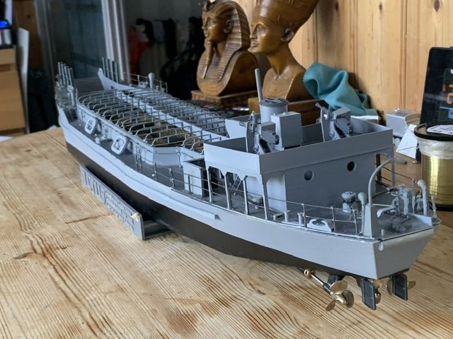
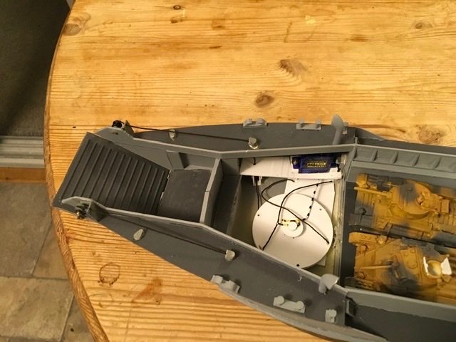
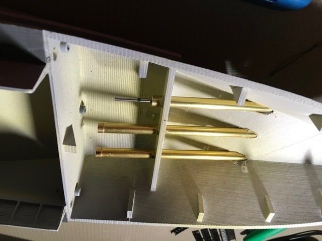
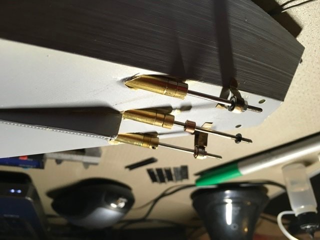
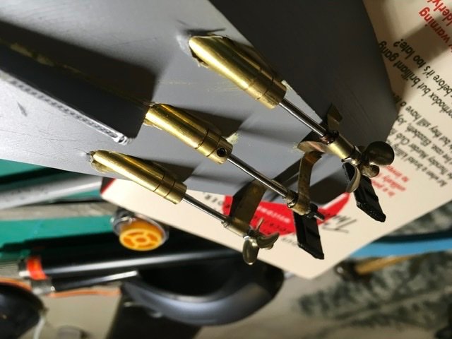
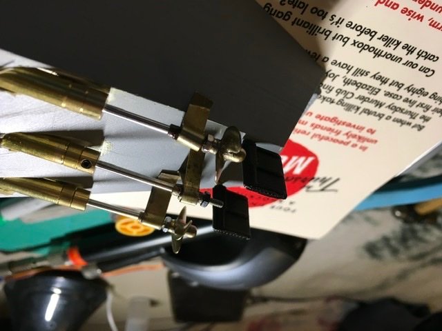
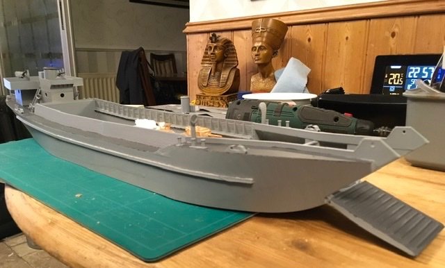
Not posted for a while, but deep in the throes of fitting out LCT119. Motor mounts and rudder gear all 3D printed of course are now fitted, however weight and space are tight so only 2 screws are powered. Screws are independently controlled. Ramp gear is fitted but the ramp still isn’t heavy enough to pull the rigging out. Currently making battery boxes for the two 18650 batteries going under the forward end of the tank deck. The quarterdeck has started to warp so I have added a subframe to keep it square.

-
The Thingiverse landing craft is an LCM, Landing craft Mechanised. These could carry a single medium to light tank, up to 20 tons. I always found them too boxy for my liking. The two LCT(4) derivatives are built from plastic sheet, with some 3D printed detail more in the case of the LCG. Francis MacNaughton has just had plans for a plasticard hull LCT(3)* to 1:72 scale published in Model Boats, April 2022. I have the stl files for LCT(2) and 3, working on a 1.
-
Current builds LCT119, LCG939 both 1/72 scale R/c
Previous builds, HMS Kent, 1/144, HMS Gorgon 1/72, HMS Scarab 1/48, SS Turret, HMS Bluebell, HMS Primula, HMS Morpeth Castle, HMST Resolve, LCT1365, LCT2477 all 1/72, all R/C
-
Very nice, I do like the Counties, such a stately ship. You model looks very impressive. Not all pointy ends are pointy, my 1/72 scale project is a landing craft, she has a blunt pointy end!
- 86 replies
-
- 5
-
-
- Australia II
- Radio control
- (and 2 more)
-
Peter Shankland wrote a book about this expedition called Phantom Flotilla, he painted Spicer-Simpson as a rather eccentric character (with some justification I believe). Worth a read. I didn’t know Deans did a Mimi. I will watch this with interest.
-
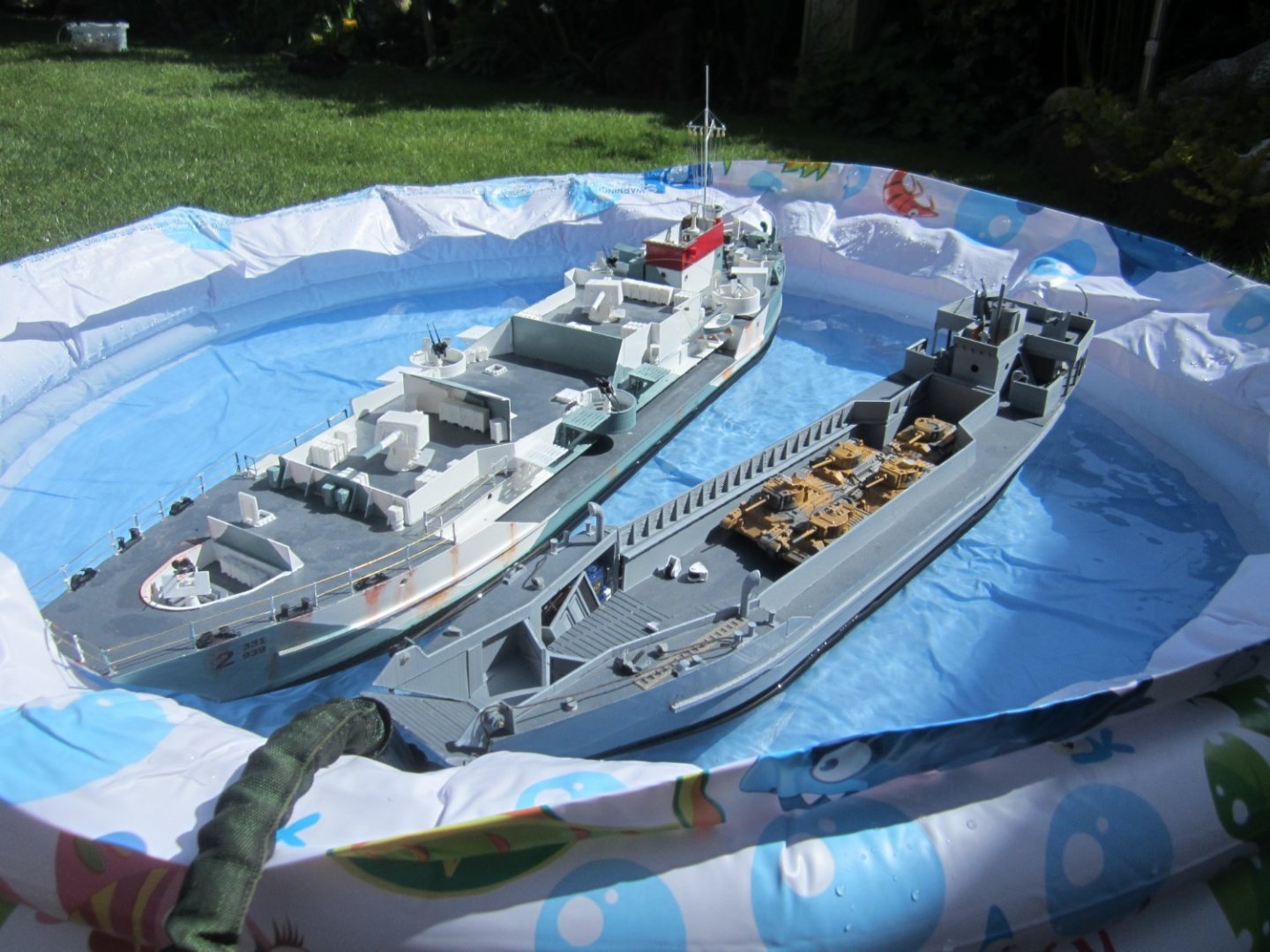
Been quiet, lots of 1:1 scale happenings and not much progress. I did get to the pond the other day to try to sail my other part completed boat LCG939 (probably the ugliest boat I have ever built). Unfortunately her motors were not up to the job and she barely made steerage way. The rudders did seem ok. Motor replacements selected and matched from my stock and fitted, couplings may need changing but ok for now. New trials next week
-
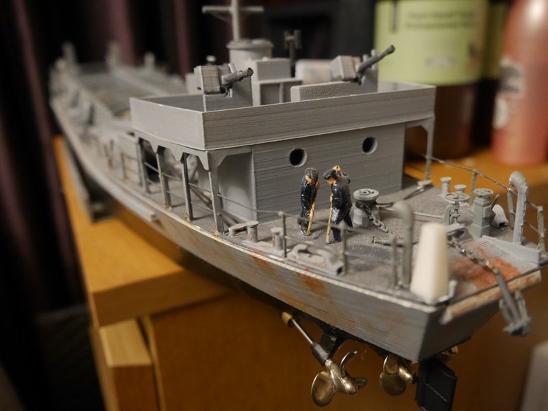
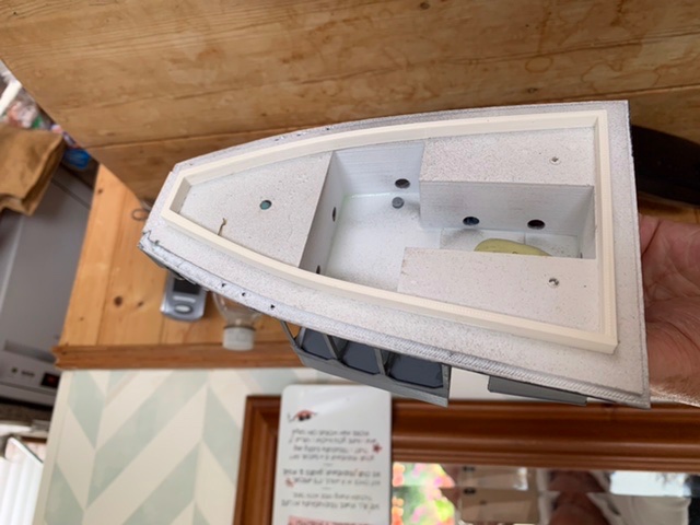
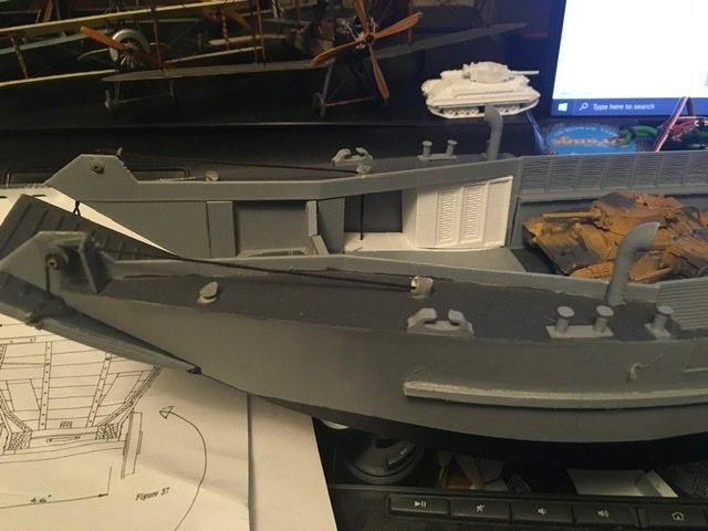
Detailing on the bow. The ramp servo needs to be hidden, but the reason it was placed there was the heads are placed in that corner of the forecastle. First print made to check fit and concept, then improved print with better louvres and gaps top and bottom of the doors. The foredeck was not good so this has been re-designed as a very thin print with the grips in, bonded to a sub-frame.
-
A bit more work, painting and making and fitting the ramp closing gear. This took several experiments before I went back to a similar gear to that in the LCT(4) at the head of this blog. The servo drive a large pulley that pulls the door shut. It opens under its own weight. The servo will be hidden by the head (toilet) doors.

-
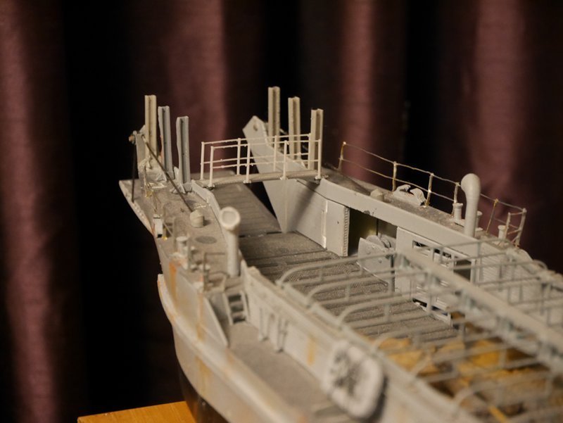
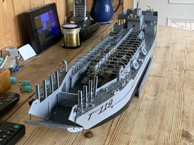
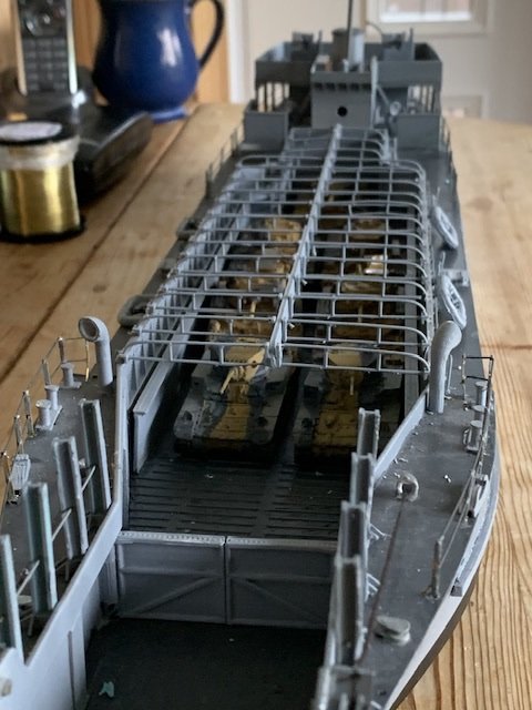
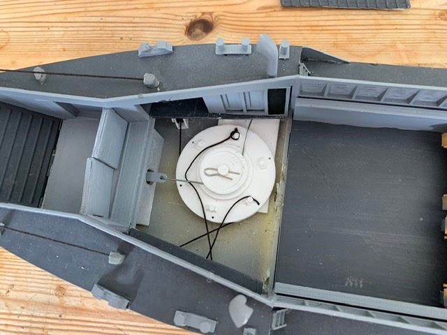
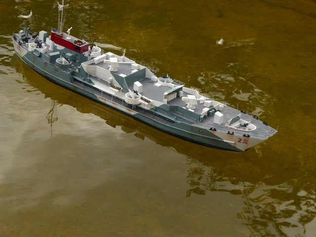
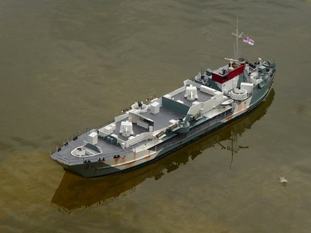
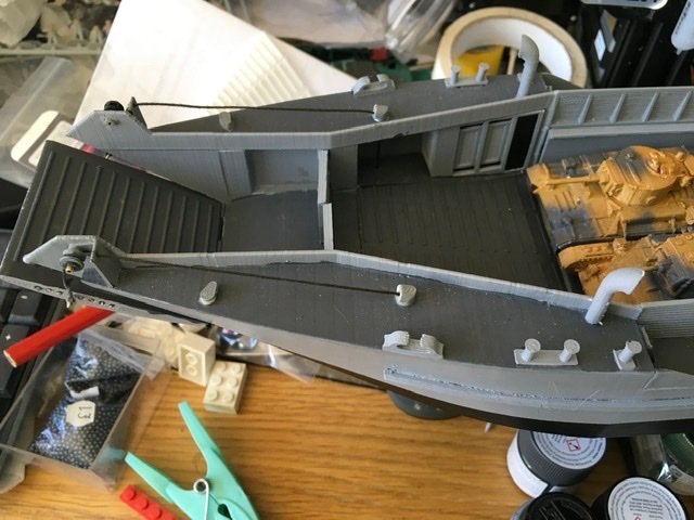
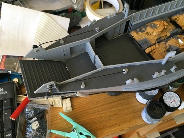
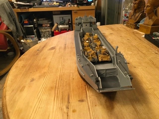
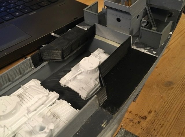
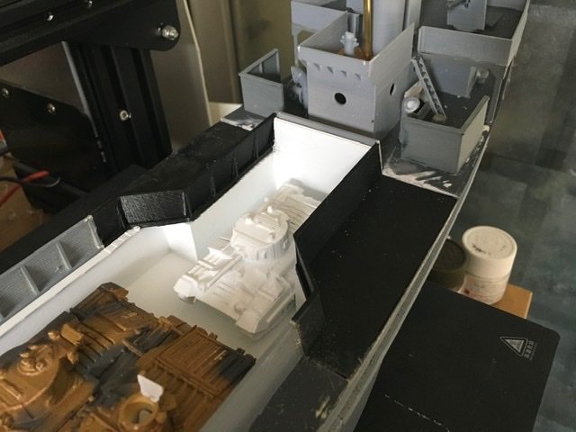
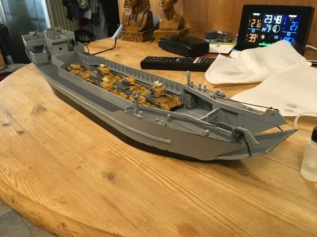
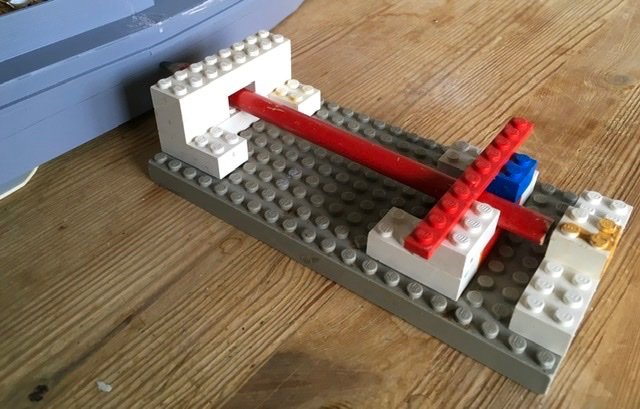
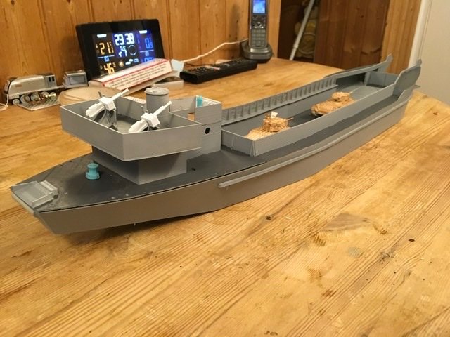
A lot happened this week on the LCT. First someone pointed me to a site that indicated the aft end of the tank deck was wrong. I had seen this before but wasn’t sure how widely is was applied. Well, to all three engined LCT(2) at least. Out came the saw and the last section of the tank deck was removed from the hull. An hour or so modifying drawings and press print. First side looked good so mirror it and print again. The tank deck also needed modification but that was fairly simple. photo numbers are inverted, I’ll get this right sometime. First photo, port side cut, starboard with new piece. 2. Both new decks fitted 3. New tank deck added. 4. Repainted, with full load of tanks (7). Started rigging the ramp 5. stern view, started rigging the ground tackle. 6. Marking the water line. Lego and pencil, you can’t beat it
-
A word about the genesis of LCTs. Churchill requested a vessel capable of landing or lifting tanks from a beach in June 1940 just after Dunkirk. TLC1 was completed by Hawthorn Leslie by November 1940. She was 152ft long, 28ft moulded beam, 5ft 9ins draught aft, 3ft forward and could land 3 of the heavy Churchill 40ton tanks on a 1:35 beach in 3ft 6ins of water. Power was 2 Hall-Scott Defender petrol engines driving twin screws for a top speed of 10 knots. Construction was in 4 parts that could be shipped as deck cargo and assembled at the port of use. Hull form was like a floating dock with tanks either side that could be flooded to balance off centre loads. The tank deck was below the waterline with a hump in the bow above the waterline to keep water out. The ramp was dropped by gravity and raised by 2 x 2 man hand winches. Armament was usually 2 x 2pdr Vickers Pom-poms and crew was 2 officers and 10 seamen. TLC1 handled quite badly at speed and had to be modified, but was otherwise successful. Thirty series 1 LCTs were built. It was quickly realised that by adding 2ft to the beam the number of tanks could be doubled, and this was the thinking behind the LCT(2). A shortage of Defender engines meant that a number of ex-aero engines of between 350 and 600hp were tried but 3 were needed. to maintain 10 knots. Dimensions were 160 ft x 30ft moulded beam x 5 ft 9ins draught. Load was up to 3 Churchill tanks,7 Valentines almost 200 tons on a displacement of 500 tons. Construction was similar to LCT(1) series. Around 75 LCT(2)s were built LCT(3) comes in May 1941 from desire to increase cargo again. The LCT(2) was built in 4 pieces, if they used 2 parallel midships sections instead of 1 the capacity could be increased. Trials indicated it worked and the resulting craft was actually slightly faster on the same power. By now the Paxman Diesel engine was available and 2 engines were used. LCT(3) was 192ft long x 30ft moulded beam and 5ft 9ins draught aft and could land 5 Churchill or 11 Valentines on a 1:45 beach in 2ft 6ins of water. Construction was similar to LCT(1) but in 5 sections. 235 LCT(3) were built, including 71 “Star” series with Sterling Admiral petrol engines. LCT(4) was the first series to break the mould. The drive for this was the need to beach on very flat beaches. First orders were placed in October 1941 for a craft 186ft long, 37ft 9ins moulded beam and 4ft 7ins draught aft, 3ft 6ins forward. The hull was completely changed being pre-fabricated in units that would fit into standard railway trucks and erected in riverside yards. The tank deck was moved above the waterline. Scantlings were cut to the minimum to keep draught as shallow as possible. Power was 2 Paxman diesels giving a nominal 10 knots. Load was 6 Churchills or 9 Shermans. LCT(4)s had a reputation for breaking their backs on rough beaches and several broke in half on sea voyages with at least 1 towing his bow into port with the stern! Later version were stiffened and made long ocean voyages but at the cost of deeper beaching draught. Around 800 of these were built. Armament was usually 2 20mm Oerlikons. LCT(5) were designed in US to British specification. The hull was short, 112ft long, moulded beam was 32 ft, draught 4ft 7ins aft, 2ft 11ish forward. Construction was in 3 pieces and they were all welded, the pieces were arranged so the vessel could be assembled afloat. The tank deck was above the waterline. Power came from 3 Diesel engines of 225hp each giving 8 knots. Capacity was 4 Churchills or 7 Shermans. I don’t have figures handy for numbers built but RN got over a hundred and the US Navy used them extensively.
-
3 screws. LCT(1) designed in May 1940 had 2 Hall-Scott Defender petrol engines of around 550hp each. These engines were also used for MLs and MGBs and were in short supply. The LCT(2) was designed in December 1940 and it was decided to try aero engines in place of the Defender but the engine available (Napier Lion) only produced about 450hp so it was decided that 3 should be used. This might give a little more speed but as the hull was very resistful, only 1 knot was expected for a max of 12knots. The Admiralty realised even then that hundreds of these ships would be needed and they could not afford to use more engines and running gear than necessary so the development of the 500hp Paxton Diesel engine was hurried up and some LCT(2) had 2 of these. Most LCT(3) and all LCT(4) had 2 Paxton diesels and were slightly slower but had longer range than the early petrol craft. The LCT(3*) had 2 Sterling Admiral petrol engines of about 850hp each but still couldn’t manage more than 12 knots. The US built LCT(5) had 3 ex-bus Diesel engines but these could only make about 8 knots. Speed on beaching isn’t needed, and in fact the anchor is fitted to the stern so that the craft can drop the anchor when approaching the beach and use it to kedge off after delivering their cargo. LCTs of series 1 to 4 did not operate from any mothership, they were loaded at the port of embarkation and unloaded directly onto the beach. LCTs of series 5 and 6 were designed to operate between ship and beach although in the initial assault on D-Day in Normandy they too carried their loads across the channel.
-
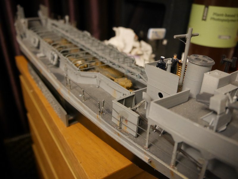
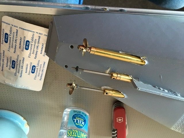
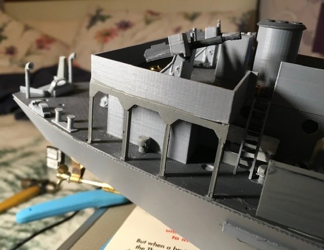
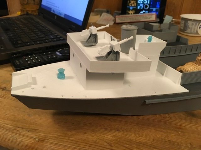
Now with outline of the ship complete, time to start on detail. Many items were common with my LCT(4) so ventilators, bitts, fairleads, all went quickly, some items needed redesigning, either to improve or to adapt for this ship, I am still printing mainly in FDM as resin is a bit offensive in the home, even using low odour resins. Ladders, hatches, engine room skylights, bridge supports, anchor davit, water tanks all done this way. Then the resin printed new designs, binnacle, capstan and capstan controls completed recently and showing clearly than this is the way forward for printing detail as they show up some of the FDM printed details. As this is an RC boat it needs it have shafts and rudders, I used M2 Caldercraft shafts which proved to be larger that I had allowed in the print, so the holes needed to be opened out to 6mm from 5, then because they didn’t look right with the shaft tube full length, it was reduced and brass shim and tube A-brackets made. Rudders are 3D printed and fitted on brass tube with the end flattened for grip. That brings us up to date apart from the next error in the build, which I found yesterday.


- 34 replies
-
- 11
-
-
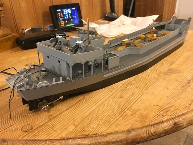
A distinctive feature of these craft is the rubbing strake along the sides. 3D printed this and result was as good,if not better than my previous styrene laminated ones. Quick rub down and two coats of filler primer, more rubbing and two coats of grey primer. Took this chance to print a Matilda tank from a file on Thingiverse to start the process of locating the ship in the Med. At this time I found from photos that the bridge of the LCT(2) was different from the 3 that I had plans for. Re-printed the bridge, one photo shows the two superstructures together. This brings us to Christmas 2021 and an addition to 3D printing capability, a resin printer, a Halot One for those that need to know. The first print off that was the capstan shown in some photos on the quarterdeck.


-
Steamboats and other rivercraft - general discussion
Andrew Egan replied to Cathead's topic in Nautical/Naval History
One type of River boat I haven’t yet seen. The Insect class gunboats were designed for a projected assault up the Danube in 1915. Most ended up on either the Yangtze or Yalu Rivers in the 1920s and 1930s. Some were used during WW2 for coastal bombardment in the Mediterranean. This model is HMS Scarab as she looked in 1931 on the Yangste River.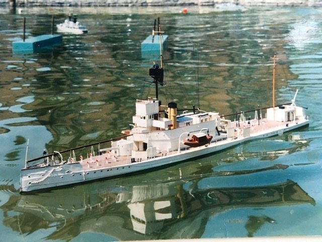
- 269 replies
-
- 4
-
-
- Steamboats
- riverboats
- (and 3 more)
-
Exploring FreeCAD for ship modeling
Andrew Egan replied to TonyM's topic in CAD and 3D Modelling/Drafting Plans with Software
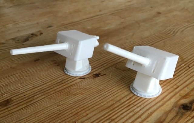
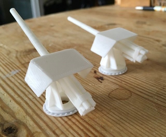
Some very thought provoking stuff on here, I too use FreeCad, I am making RC models. I started in January 2021 designing and 3D printing at first for a styrene LCT model at 1/72 scale that I built about 20 years ago but didn’t quite finish. Then moved on to an LCG as I had built 2 hulls. The LCG had stalled on the armament, I drew the single 4.7” gun mounts in FreeCad. Took a couple of false starts but even the first efforts were good, printed on my Ender printer they were instantly better than I expected. Have to say I am a complete FreeCad addict now, drew up a D-class Fairmile hull and LCT2 and 3 hulls and detail. The LCTs are very simple until you get to the bow which was tricky. Key items for me are the loft and b-spline tools, thickness can be useful as well. Recently I have been designing for resin printing which really shows FDM up, but FreeCad has been excellent. The hand wheels on the capstan controls are 0.5mm thick. Couldn’t do that in FDM, in FreeCad I could even draw the rivets on the capstan brake band, and they are visible on the print.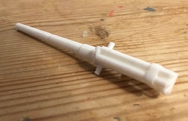

-
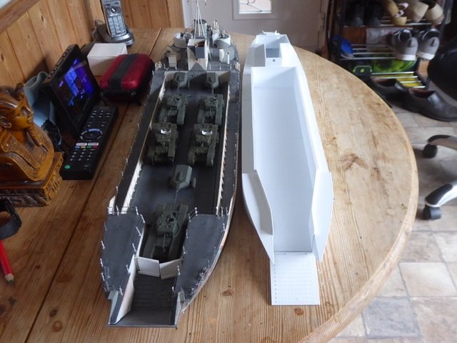
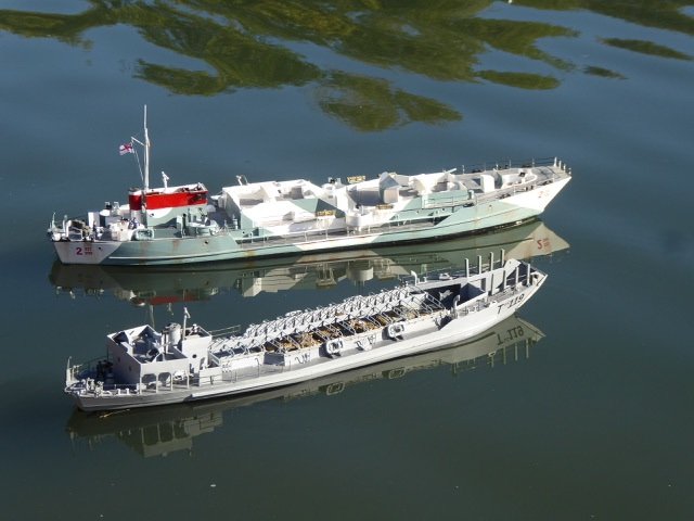
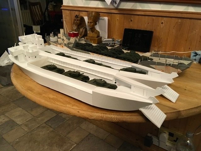
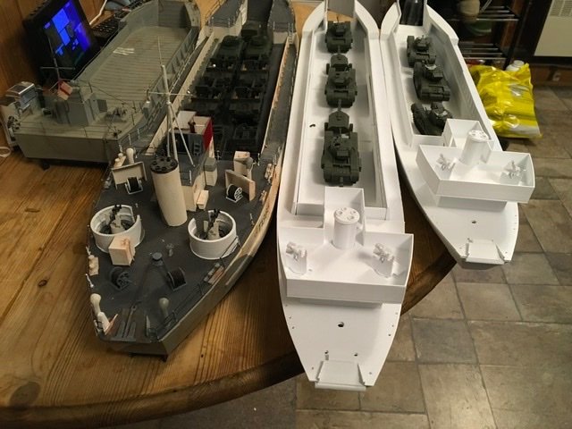
While not faultless, these parts were good enough to build into a ship model, I had enough parts to make either an LCT(2) or 3 but decided I wanted a 2, representing the very first ships of the class, many of which were sent to the Mediterranean to support the Eighth Army. The sections were glued together using Milliput as a filler and bolted using M3 screws and nuts. Surplus Milliput was removed before it was dry. Side decks were fitted using Uhu glue (cyano also works well). Meanwhile, the LCT(3) sections were glued together using Uhu and bolted to test different joints. Meanwhile, while the big sections were printing I needed a change, so the bridge deck, funnel and 2 pdr guns were designed and fitted into the print schedule, happy with those immediately. One of the differences between the 2 series and the 3 was the number of engines, the 2 was given 3 engines in a bid for more speed, the 3 series reverted to 2 engines. This meant that the 2 series stern is different to the 3 series and that funnel had to be remade with three main exhausts in. Two of the photos below show the 2,3,4 and 5 series LCTs together.
-
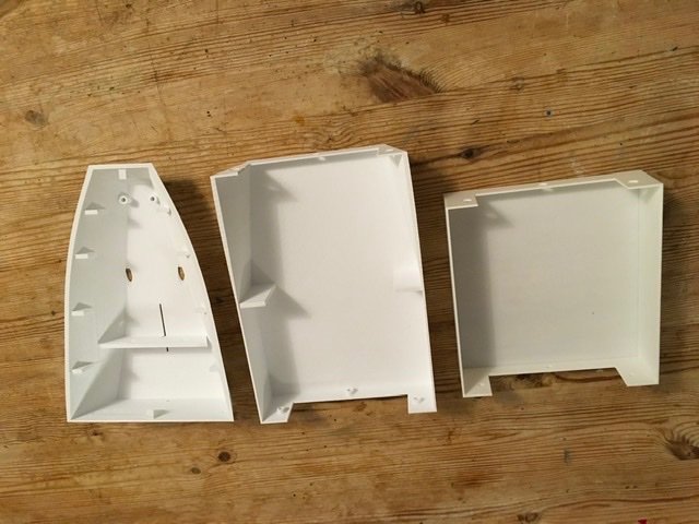
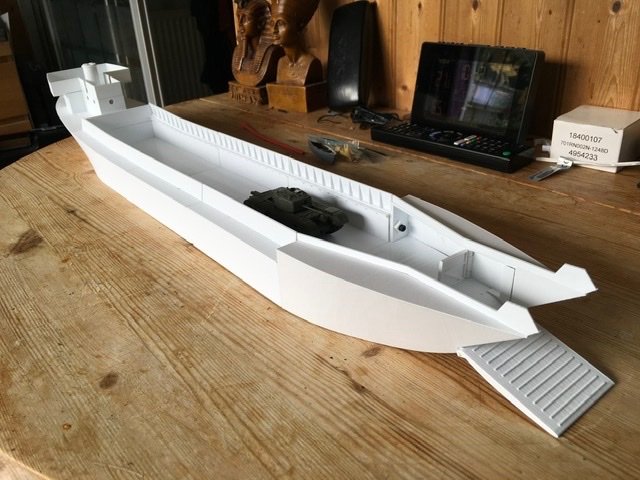
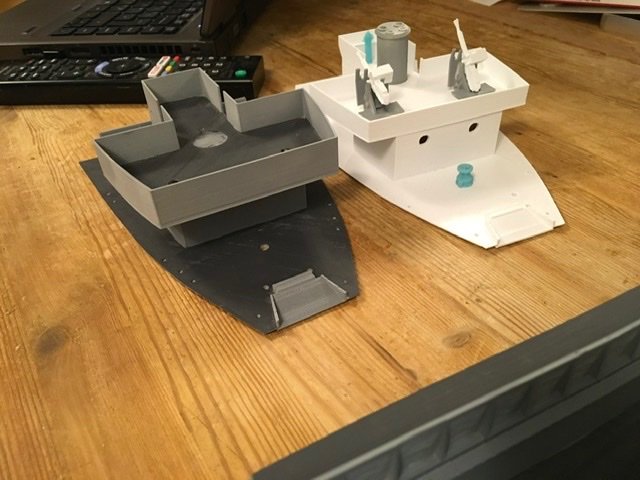
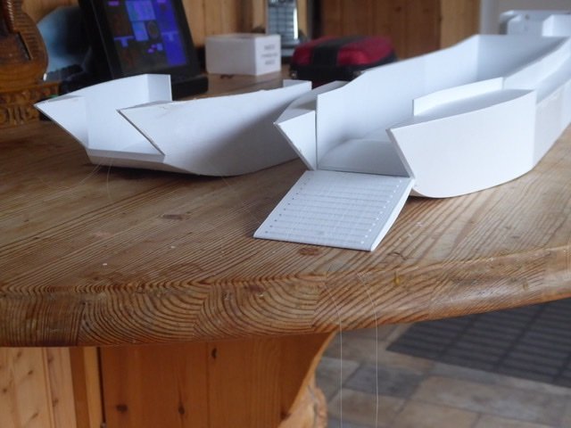
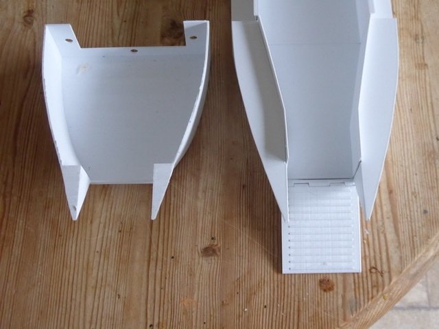
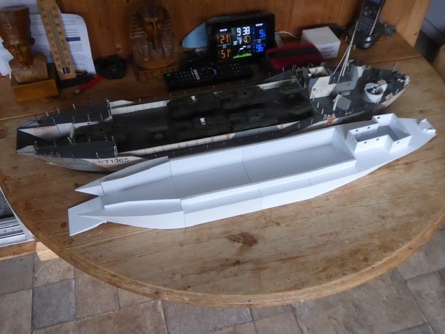
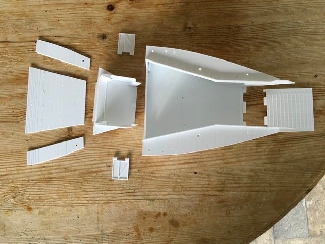
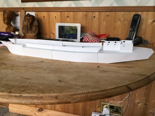
Then I went to Portsmouth to look at LCT7074, one of the few preserved LCTs. Suffice to say I came back and scrapped the lot. The bow was wrongly drawn, side decks were wrong, stern needed small changes. I use FreeCad so most of the drawings could be corrected but not the printed components. New hull parts and decks were printed. The quarterdeck had been drawn but the opportunity was taken to tidy it up and integrate the base superstructure into it. The bow of an LCT is actually quite complex and I wanted to fit a working ramp so design work started on this as well. The first attempt was just not good enough, it was impossible to put together so was redesigned and was very successful. The new bow worked as well, the new design could be printed in one piece including decks. Pic 1 and 2 show the new and old bows, old on the left in each pic. Pic 3 shows the new pieces dry assembled as an LCT(2). Pic 4 compares the LCT (4) with the LCT(2) right. Another consequence of this stage was I found inaccuracies in the calibration of the printer that need thinking about before any more large prints. Pic 5 shows the assembled final bow, pic 6 the bits needed to make it


-
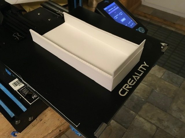
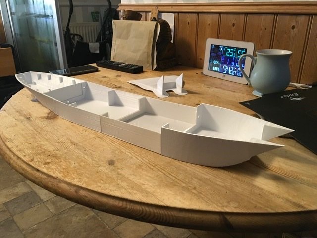
This is ship modelling I hear you say, not plastic shoeboxes, well, first, LCTs varied from 300 to 550tons and varied between 160 and 192ft long, definitely big enough to be a ship, second, they made voyages from UK to Alexandria on their own bottoms, definitely the job of a ship. The drawings I had at the beginning would not allow a super accurate model and the process of 3D printing on an FDM printer gives a finish not good enough for super plating detail. The last hull piece drawn and printed was the bow, in design the most complex. Side decks on the midship sections had been designed separately to minimise printing supports and these when glued on really stiffened the hull sections. The tank deck sections were to be removable and were printed separately again. The first picture shows the assembled hull pieces for an LCT(2), the second has the side decks and quarterdeck added. So far, all pretty straightforward, and it is the middle of October 2021.
-
After a twenty year break from ship modelling COVID got me looking for something to do. Just before I had stopped building I had started 2 LCT(4) hulls in styrene sheet. One of these was only a hull but the other was well advanced and had actually sailed as an RC model. I did some detail work on this, modernised the radio and sailed it. First picture. The second hull has also progressed but is not yet complete, could be the subject of another build log. For Christmas 2020 I got a 3D printer and after a while started to wonder whether I could make a printed hull. An LCT hull seemed to be a good place to start as they are relatively simple. I already had a LCT(4) and an LCT(5) so I thought an LCT(2) or (3) was a good option. These two variants used the same basic hull but the 3 was longer by 32ft. This choice was confirmed when a friend sent me a builders plan for an LCT(3). Drawing started in August 2021with a midships section, the easiest, as everything is nearly square. Second picture is the aft midship section on the printer, the third, the stern, aft midship and midship sections