Yorky1
-
Posts
21 -
Joined
-
Last visited
Content Type
Profiles
Forums
Gallery
Events
Everything posted by Yorky1
-
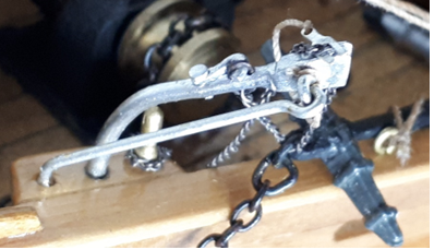
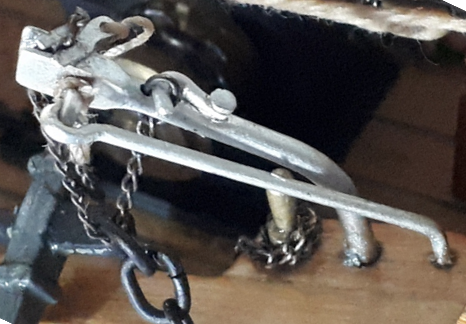
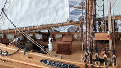
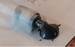
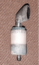
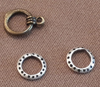
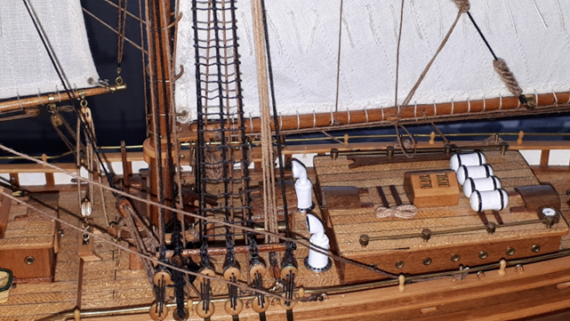
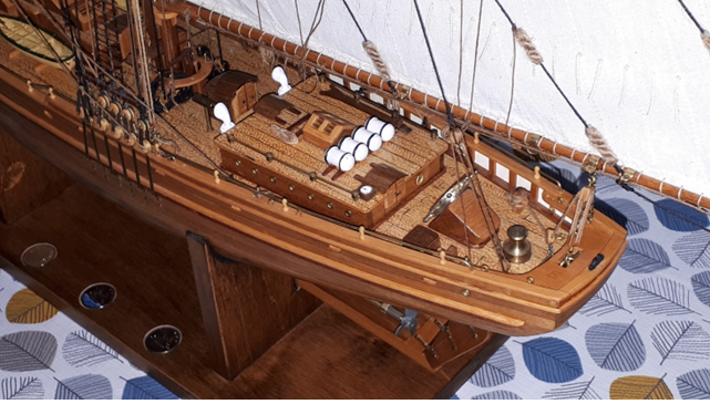
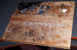
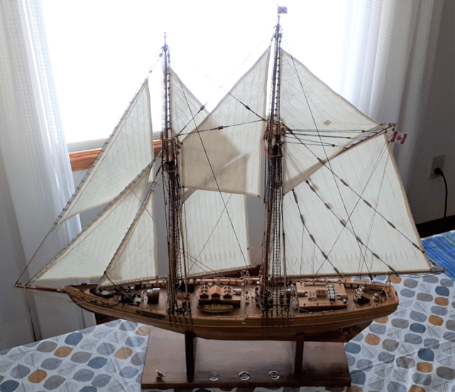
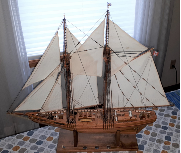
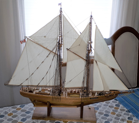
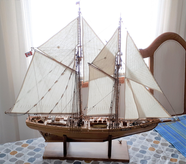
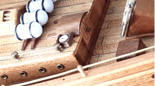
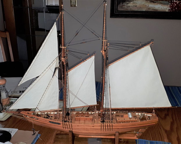
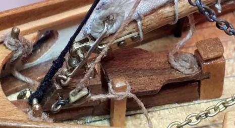
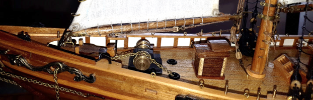
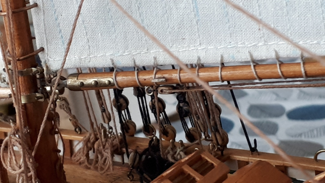
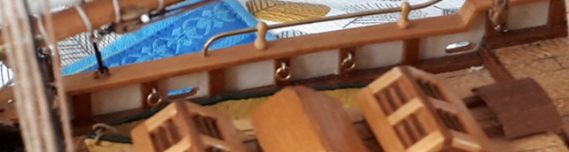
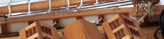
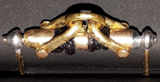
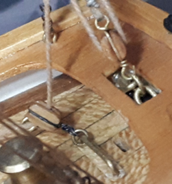
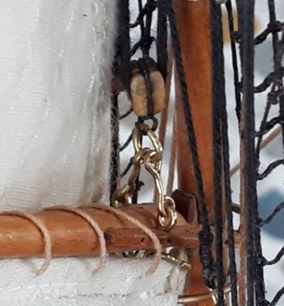
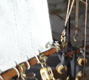
 Here, a finished cathead, sprayed with light coat of dull silver. The chain retainer plates have lanyards attached. Installed; port cathead Once positioned for height and rotation, I added a drop of cyano glue.... and stbd cathead installed... You can see the fine chain that threads through the anchor shackle, the chain retainer plate on top, the chain-end loop and the latch holding it. The remaining length of fine chain is simply belayed on a pin to keep it form getting in the crew's way. End of July 2023. Finished! Oh, except I forgot the air vents/funnels. I had removed those for access while refitting, so now I looked at them and couldn’t bear to fit those horrible items from the kit after all the work I had done. SO… for the forward vent, I cut a thin-wall brass tube (old telescopic antenna tube) for the height and a few thin rings from the same tube to solder around. I epoxied the assembly to one of the kit vents and left overnight. Then I laid the item horizontally on paper and built up epoxy around the funnel top, so that it dropped down to the paper and formed a ‘cone-sort-of-shape’. I left it overnight. Above, I had just filed to shape , hollowing the funnel mouth slightly and painting; compare with the original item. This is now close to the correct funnel as shown in Jenson’s book. Much better. The brass tube etc. was a lot of work and the aft air-vents are wider cylinders, so I tried wrapping paper around another original vent and holding with cyano-acrylate dripped into the coils Above is the paper-wrapped vent next to the remaining original vent and after filing the cylinder-top down to the required step. Below, the next step – held down horizontally with the steel epoxy formed into a cone and curing. After epoxy cured and filed down to shape. The inside was carefully recessed with a Dremel and burr cutter, the hole refined with a twist drill and painted black inside. The real aft vents in Jenson’s drawing have a wider flange with many bolts securing it to the deck. My wife provided some unused plated jewellery rings for this. I nipped and twisted off the thick section, filed the ends flat and squeezed the ends together- ahhh - just the right size to fit the cylinders. Then I filed the tops and bottoms flat and the outer edges too. Then chamfered the top edges and used a pin-vice with a tiny drill to make small indentations as bolts. I dipped the end of an even tinier drill in black paint and dabbed it into each hole. The aft air vents, painted and installed.... Note, I had to make new holes in the deck for all those vents because the kit plans had made me put holes much too close to the buildings. The new vents simply would not fit so close to the buildings and nor should they. Jenson’s book shows quite clearly that the vents are sited clear of the deck structures. The view above also shows the helm compass in the main cabin rear wall. I added that at the last moment. Now, if I could just have moved that winch back to the correct place, and…and…. ** I finally declare my Bluenose II complete and ready to entertain all who see her! ** ** 1986 to 2023 ** The old, trusty building board I made up in 1986 has been thrown out and the table cleared of all tools and supplies. The building board gradually became a place to mix glue and paint and file parts! So here it is. Three, slightly different, Canadian 10c coins, featuring the Bluenose II are set into the base. The centre coin being a special mint with a blue ocean. That's wit backlit sails, and below with front flash exposure.. Finally, below, are stbd side -with front flash exposure... ...and below, backlit sails. A long process but well worth it. Thanks again to those who helped.
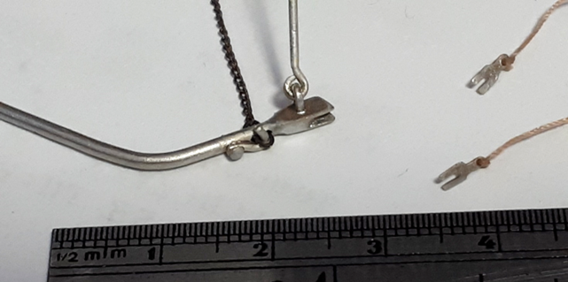

- 15 replies
-
- 2
-

-
- Bluenose II
- Artesania Latina
- (and 1 more)
-
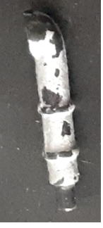
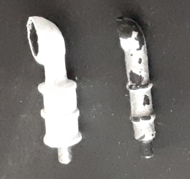
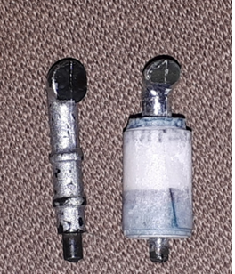
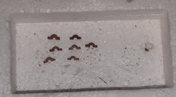
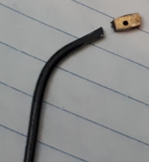
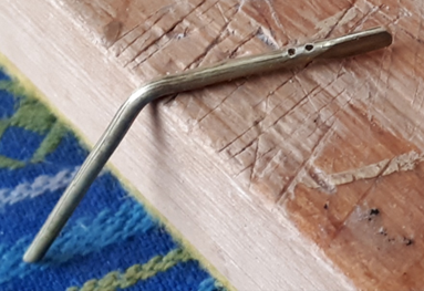
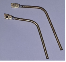
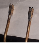
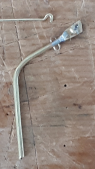
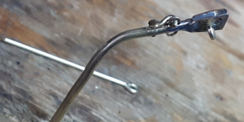
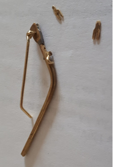
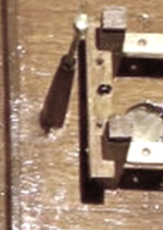
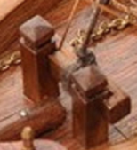
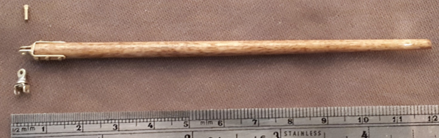
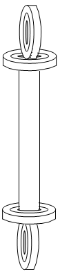
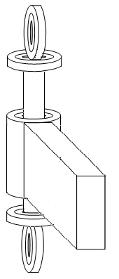
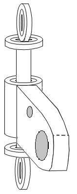
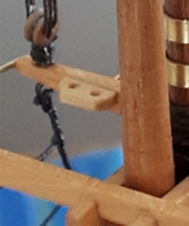
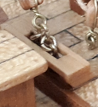
At the end of April this year (2023) I made a small compass in its box, for the main cabin roof. I used some leftover outer planking strips from the kit to make the walls, with thin strips glued in the corners, like the full size shown in the Jenson book. I glued another couple of pieces of plank material to the base then sanded and varnished. I used a leftover piece of dowel as the compass body, cut to size and sanded down. I glued two tiny, rounded pieces of wood to the sides to represent the gimbals and painted the face white. I drew a needle and some marks with pencil and spot glued the compass inside the box. I glued this in place to left of the rear hatch. The cabin’s brass rails from the AL kit were originally curved around at front and rear ends. The real Bluenose II seems never to have had these; they were, and are, wooden rails; but too late to change now. However, I did clip the curved ends off, to allow the compass box to sit there. May 2023 Only a few small items in rigging to finish. First the ensign halyard, laced through the small block I had attached to the main gaff end. I formed two small loops for the flag and joined the line into a continuous loop, then belayed it on the boom cleat, as the Jenson book specified. The two lines would not lay nicely; they kinked left and right as they flowed down. So, I rubbed wax into them and then pulled both together through my fingers. Now they sit together and can be formed into a smooth curve, as if the weight of the rope makes them hang properly. Next, the lazy jacks. The Jenson book points out only two lazy jacks each side, on the forward topping lifts, whereas the online pictures show at least two variations with more lazy jacks. However, the ship definitely has changed through the years since Jensen made the drawings, so what to go with? Well, the two in Jenson’s book are almost unnoticeable so I decided to add 2 each side to the mid topping lifts, as they appear in a 1978 picture on the internet; Jenson’s book was done around then, so the extra lazy jacks in the 1978 picture are quite typical for that time. I then made the tiny wooden eyes for the boom, to retain the lazy jacks. These are from the thicker walnut strips that were leftover in the kit. They are almost the right size; maybe slightly too large but I couldn’t work on anything smaller. As it was, some of the tiny pieces of wood flicked off the tweezers and disappeared forever and some split the wrong way with the knife. So, after cutting and sanding these I had seven wooden eyes to attach. Picture shows the eyes in one of the kit’s foam box recesses. They are very small! I fixed them to the boom sides, over the lazy jacks, with cyano glue. Why seven? Well, when I located the lazy jacks according to the pictures, relative to the baggy wrinkles, one ended up exactly where I have a cleat. So, I simply left the eye off that side. Then the main gaff downhauls. I already had the short piece of rope in the gaff end and small eyes formed in them, so I joined two long pieces of line and belayed them as per Jenson’s description, on the aft lazy jack wooden eye (another reason I needed the wooden eyes!). Finally, the anchor catheads. The ship is mostly complete now, so I must do these. The original items were cast metal as shown here. I actually couldn’t find these after a few years, so bought some brass ones at a hobby shop in the USA one year. Later, I found the originals again so fitted them. Unfortunately, they are not accurate enough for me, so I tried to modify one. I twisted until the glue broke free and then pulled it out. I glued brass plates to the sides. Then I tried to drill a tiny hole through the cathead’s shaft, just behind the plates, and that resulted in the metal breaking! So, I will now use those new brass catheads that I bought. I can solder to those and drill them, so they are much better. I started by proving that I could drill holes. Yes, two tiny holes on the first one. These will represent the slot for the small chain’s end-link to attach. June 2023 I soldered two brass plates to the sides of each end (the last remaining pieces of brass strip from the kit). I sawed the slot between the plates to ensure it was clear for the chain, then filed the outside to get the final shape Next, to drill a hole in the side for an eye, plus clear out one tiny hole in the top that was covered by solder. This, below, shows the loop I made for the small chain, plus the beginnings of a hook to latch the chain loop. …and below, with eye and latch installed. Behind is the start of a ‘prop’ rod. Now, the second cathead and chain retainer plates... next, installing the catheads.
-
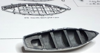
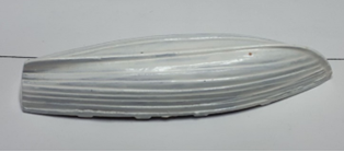
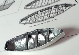
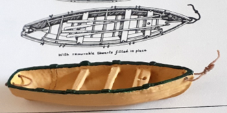
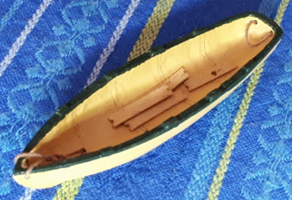
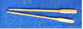
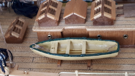
Dory Modifications The AL kit dories were simple cast items with solid metal throughout the bow, stern and seats. AL said to simply paint the hull white and glue onto the deck, upside down. Yuk. They are also the wrong shape but I couldn’t alter that. However, I could make a big difference. I used a Dremel tool with a round cutter bit to remove the solid metal blocks at the bow and stern and under each seat. I drilled four holes for the ropes (painters?) in the bow and stern and a hole in the front seat for the dory mast. Then I painted the inside and out with acrylic yellow ochre and a dark green around the top rail. and rigged those ropes shown in the drawings. For the second dory of the kit, I removed everything and made wooden seat boards. I painted these and dropped them into the hull. I had just finished making some tiny oars and dropped those into the boats... Those were VERY delicate. I touched the fine grit sandpapaer very gently to them while shaping! Next.. The end of April and a few extras.
-
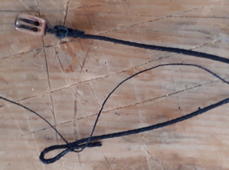
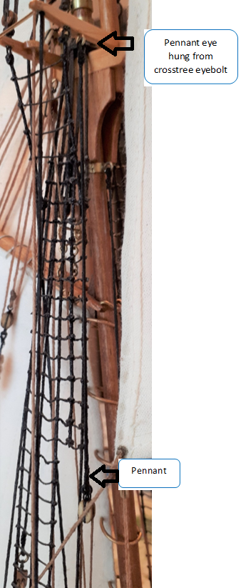
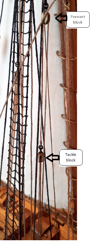
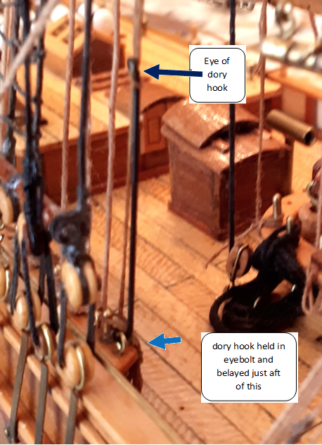
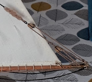
This is where I began the long Refit! Now the mobile back stays for the top masts. I had just fitted these, as to the kit’s plans and instructions, back in 2021 when I realised the Jenson book did not agree at all with the kit’s design. That was where I had begun my refit. So, finally, I am fitting the backstays in the correct locations. Here, the double block for the purchase is ‘shackled’ to the lower end of a backstay and the mast eye is being prepared. According to Jenson, the foremast backstay should go to “a ringbolt on deck at the main shrouds”, although it doesn’t show where, and there is no available ringbolt there, either on my ship or in the drawings. I studied the drawings some more and corrected the foresail halyard purchase belaying locations, moving the deck block, belaying again and coiling the spare line under the rails again. Dory Hoists I studied the dory hooks and hoist rigging in the Jenson book then looked in photos on the internet. Unfortunately, none of the internet pictures show the entire dory hook rigging from crosstrees to deck in high resolution, so I cannot zoom in to see the details of where the top pennants come down to and exactly where the lines belay. Also, the internet photos are of the new Bluenose II so the dory hook securing method is different to the Jenson book. My pin rails are by now a bit of a compromise anyway, due to building them to the AL plans then drilling for extra eyebolts and pins as to the Jenson drawings, so I picked the closest and most suitable eyebolts for securing the dory hooks and used the nearest pins to belay the line. I made the hooks from brass rod and blackened it. Then I jury rigged one pennant and hoist with sewing cotton and tried raising the hook to the highest point and the lowest point. I discovered that: 11. With the top pennant too long, the block on its lower end prevented the hoist from traveling enough. 22. With the dory hook looped to the line at the wrong point, that also prevented the full range of hoist travel. I progressively shortened the pennant until the hoist had enough range, then moved the hook along the line until it would lower the dory well into the water and raise it well clear of the rails. I then made the required eyes and ‘shackles’ (brass rings, blackened) and assembled the hoist, pulling the belayed line just enough to keep the whole hoist in tension .. and below is the next, lower section... ... and the lower part, with hook secured to eyebolt and line belayed... Next: Dory Modifications.
-
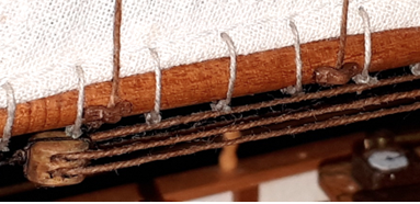
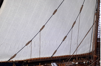
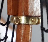
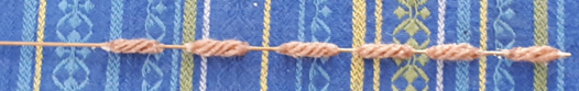
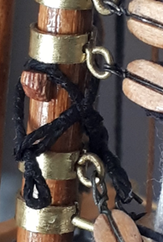
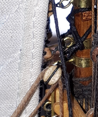
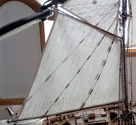
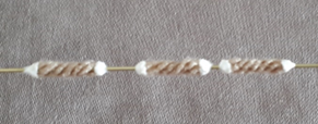
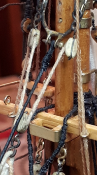
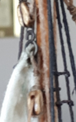
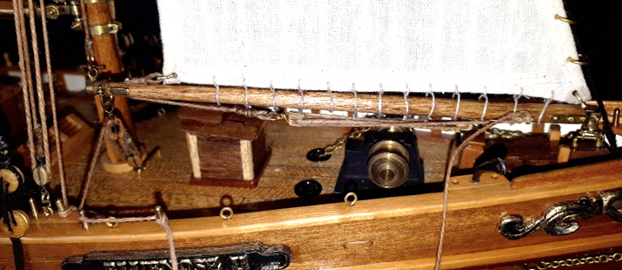
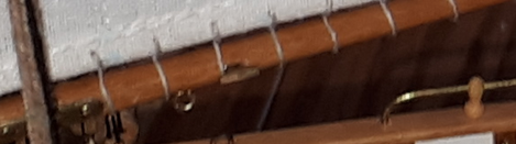
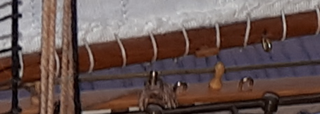
By this stage I was keen to go that bit further and I elected to stitch the upper mast rings to the top sails. So for the top sails, I was then able to open up all of the rings, slide them onto the mast all in one go and close them back up. (For the lower mast sails I had simply pierced the sail cloth with the rings). Below is an overall view of the ship before the top sails were mounted. The somewhat complex fore boom end-lifts are visible if you look closely. Although my futtock shrouds were done to the AL plans, using ratlines, and I couldn’t face redoing all of that, I did make futtock stay bands out of brass strip, as per the Jenson book and real Bluenose II, and secured these in the correct positions, near the top of the lower masts. I found this necessary because the foresail and jumbo-jib boom end-lift pennants are suspended from these bands. Here you see one of the futtock stay bands with eyebolt for the end-lift pennant. 2023 March. I just HAD to have baggy wrinkles to look good. I found a way to make baggy wrinkles that don’t look too bad at this scale (1:75) when you stand off a bit. I found a small sized multi-strand wool and used tacky, white pva glue on the ends to hold the fibres. My end lift and topping lifts are thick black thread, the same size as the shrouds, rubbed with a thin cabinet-makers wax and with a drop of superglue here and there, to stiffen the thread just a bit, more like the wire cable it represents. I tried to thread this with a needle through the wool section but the first version was not very good. My final method was to use a brass rod, large enough to allow the thick black thread to pass through. I smeared Vaseline thinly onto the rod then slid the wool ‘tubes’ onto this. Then I applied the tacky pva around the ends of the threads, ensuring it stuck down to the rod as well. Once dry, the glue had contracted a bit and turned almost clear. The Vaseline worked as a release agent, allowing me to slide the ‘baggy wrinkles’ off then I trimmed the excess glue off each end. The hole left in the glue was just right for the black thread and needle to go through. I seized an eye at one end of the thick thread, attaching to a block’s strop-ring as I did so. I then threaded the baggy wrinkles on before seizing an eye at the other end. For the boom’s end lift, I attached one eye to an eyebolt on the mast cap. The lower end is attached as shown in the Jenson drawings, by two blocks to the boom end eye and then through two pulleys in the boom and forward, through eyebolts (representing the fairlead tubes) to the fixed belaying pin on the boom’s jaw. (My foot ropes are seen here, too. Same thread as the main boom lifts and attached with small brass rings as shackles) For the forward topping lifts, I already had double blocks attached to the rear of the trestletrees... ... so I reeved those and the lift-cable single blocks with natural rope-coloured thread and led the lines down to the shrouds’ pin rails, where I belayed them. The lower ends attach by eye to the boom’s bent shackles. For the aft topping lifts, I made two cable beckets and wound them around the mast, where I had glued tiny wooden blocks, using real pictures of the ship’s mast as a guide Above is port side view with no block yet on the becket. Above now is the stbd side with block on the becket. 2023 April 2nd The last main boom topping lift just went in, with baggy wrinkles. At first, the tackle at the top of each lift looked bad because the thread was slack and baggy. This is because the black thread of my cables is not heavy enough to put tension on the tackle’s line like the real steel cables are. I thought about this and pulled the tackle’s line taught then dripped superglue along it, holding for about 1 minute. The result was a straight, stiff set of lines between the blocks! This allowed me to have the black ‘steel’ lift cable a bit slack, like the pictures I have seen of the real ship, and the tackle remains straight (under ‘tension’ of the ‘steel’ cable). Looks much better. Above shows the stbd side. Notice also the reef points in the main sail. I added some in the fore sail too. ..Next.. I am back to the point where I began the Refit!
- 15 replies
-
- 1
-
-
- Bluenose II
- Artesania Latina
- (and 1 more)
-
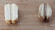
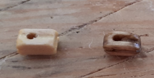
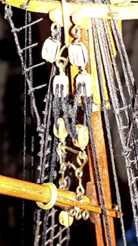
Fife Rail I carefully and slowly cut the incorrect front bar from the fife rail, trying not to damage all the finished deck, structures and rigging that were in the way. I made a new, larger cross-bar from two walnut strips, butt-glued together, cutting out two square holes to slide down over the bitts. Then I cut out a rectangular slot for the fore boom crutch to slide through. I added two fillets under the fife rail, up against the bitts, as in the Jenson book and shown in photos of the current Bluenose II ship Here the foresail sheet is belayed on the bitt, as it should be. The huge bilge pump from the kit was well glued in some years ago as well, so I couldn’t alter that without damaging a lot. Lines and Threads The kit had enough larger thread for shrouds and stays (although they were brown so I had to black them) and the kit’s smaller sized, white thread worked for lashing sails to booms and gaffs, but I needed much more thread to make all the lines. I found two main sizes for the running rigging and dyed them in tea to get a fairly realistic rope colour. For ratlines I needed more medium black thread so used a medium-thin black cotton thread and used a thin black cotton for some seizing. I found a pink thread just right for the deadeye lanyards, so had to black those with a permanent marker pen. I tried beeswax on the threads but found it was rock hard and even when I melted it, it began setting as soon as I began dragging thread through it. Much better was Burts Bees Lip Balm. That soaked in nicely and both damped the fibres down and stiffened the lines a bit. Later I used an old tin of Craftsman furniture scratch remover wax. It did a reasonable job of making the thread more like rope. Running Rigging I followed the Jenson book and began making up blocks and lines and shackles and sister-hooks. Each block from AL required sanding to a more scale profile; some smaller blocks reducing to a round shape and others to an oval shape. All needed the holes drilling slightly larger and pulley slots carved, before staining, weathering and varnishing, plus stropping with either black steel wire or blackened brass (where hooks were required). Here you see an AL block before modifying, then the carved, drilled, sanded, dirtied and varnished item. Sisterhooks are nigh-on impossible at 1:75 scale so I made brass figure-eight links as sisterhooks, bending them open to attach, then bending closed again. I used these everywhere they were specified in the Jenson book. I started with plain brass but later I began blackening them as I made them. Here shows the corrected rigging of the jib sail halyard; the 'sisterhooks' on the bale here are some of those I blackened, while the lower 'sisterhooks' you can just see are natural brass. The mix of finishes in different places is quite pleasing. For attaching to top-sails, I made one half of the 'sisterhooks' at a bit larger radius to get its ring through the sail grommet. Here, the clew line block and its lanyard is attached to the sisterhooks, as Captain Watson informed me they find this easy to attach or detach during the season. I rigged the fore and main halyards before attaching the lower sails, adjusting these so that the gaffs followed the top line of the lower sails as I held the sails up to the masts and booms. To follow the correct rigging shown in the Jenson book, I added all the required extra blocks and lines for the sails, plus the chains on two of the jib sails. I removed all the AL kit brass rings I had put on the booms and gaffs and lashed the lower sails to them as they should be. I needed those brass rings for the fore stay sails and I also added many more rings because the AL plans did not show nearly enough. I also had to get more of the large brass rings for the mast than the plans showed, to agree with the Jenson book. The jumbo jib and fore stay sails went on next. I asked my wife to remake a few top sails because they were the wrong size or shape from the plans. I elected to have the bolt rope inside the edge hem so she laid it in as she folded the edge then sewed the edge down. I find this much neater looking at this scale than trying to stitch a bolt rope around the edge. The first sails were made to the AL plan with a loop of bolt rope protruding from each corner to attach the lines. However, that attachment method didn’t look good, so, I tried folding the loops back over themselves to form a grommet, which I glued down with cyano and held flat between pliers as it set. Much better than the AL idea, although when I needed to remake the top three sails to fit better, I asked my wife to make these with no bolt rope loops. I simply made a hole in each corner with fine tweezers and opened it up enough to get the lines through, then soaked the hole area with cyano. I also used a fine tip gold paint pen to outline the holes, to look like a grommet. So I have learned and improved all the way along. Top sails, particularly, needed correcting to achieve the fit to gaff and mast and to tuck down below the gaff near the mast, as seen on the real ship pictures. I added a small square of sail cloth to the middle of both top sails, glued and edge-stitched, to which I sewed a blackened brass ring for the clew line. The Jenson book does not show the topsail clew line block attachments in sufficient clarity to see how they should be attached, but upon advice from Captain Watson of the current Bluenose II, I made up a single block on a lanyard that attaches to the ‘sisterhooks’ at the topsail peak and the clew line downhaul runs from the clew, through the ring in the sail centre and up over the clew block, then down through the crosstree fairlead to the deck where it belays on a pin rail. Captain Watson also offered some advice on the topsail halyard blocks. The Jenson book does not show this clearly, but in fact the crew has learned to mount the topsail halyard’s upper double block so it lies flat against the mast with the hauling end leading from the forward, starboard sheave. In this manner, when the halyard is pulled from the mast they get the fairest possible lead to the deck. If the block lies with sheaves fore and aft, the halyard tends to lick up more Vaseline from the mast. Next: More on the Upper Sails..
- 15 replies
-
- 1
-
-
- Bluenose II
- Artesania Latina
- (and 1 more)
-
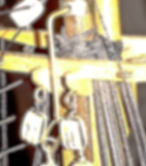
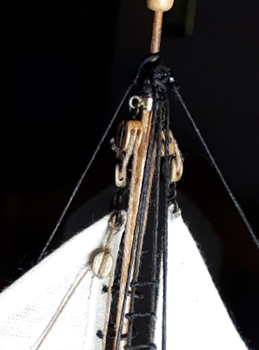
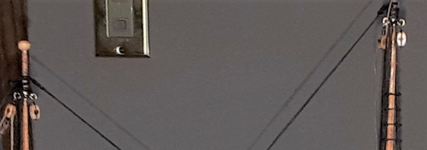
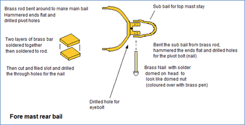
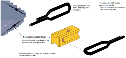
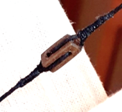
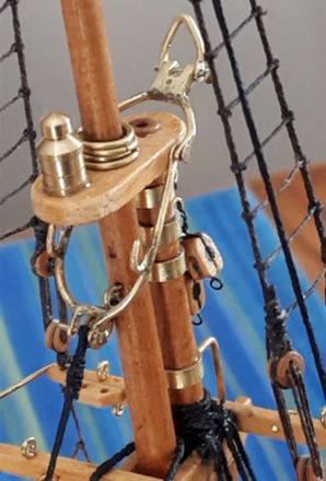
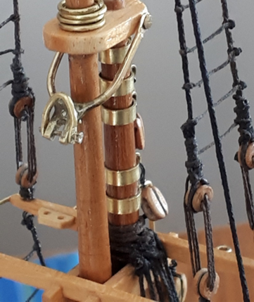
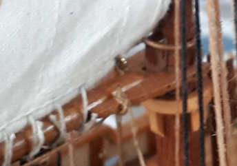
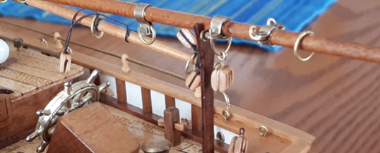
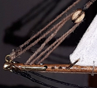
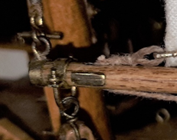
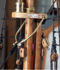
Top Shrouds and Stays I had to redo the top shrouds and stays, to get more like the Jenson book, so removed the tops and the ‘wired-on’ blocks at the top of the mast, with their eyebolts. I made wyes from brass bands and eyebolts and moved these down a bit, to look more like the real ship locations, then remade and attached the blocks. By April I was making special brass bales for the upper masts, to attach the triatic stays and forestays. After asking Captain Watson of the Bluenose II about the blocks on the triatic stays, I learned that they were ceramic insulator blocks. I simulated those from spare walnut in the kit. Very fiddly at this scale – I broke the first one. I then remade my ‘first-attempt’ two-piece jib-stay bail because it was flimsy and I needed the new rear bail adding, plus hooks for the jib-sail halyard blocks. This is the foremast top, after bails and new fittings were done …and the main mast bail assembly... The resulting action of having the triatic stays connected by these bails is quite interesting. With only fixed threads connecting the masts, I had found that when I pulled or pushed against one mast slightly, most of the stays went slack. With this arrangement of bails, fore/aft pressure on a mast seems to move all stays and bails at once; self-adjusting and maintaining tension! * I made bulwark deadeye fairleads from small glass/plastic beads with holes large enough to take the running rigging. I bent brass rod into the required shape and soldered the ends together after ensuring the bead fitted snugly into each one. Then glued the beads in with cyano. You can just see one on a starboard stanchion here, near the bow. This one is ready for the jib-sail starboard sheet. Bowsprit Bitts I went back and cut out the incorrect bowsprit bitts and crosspiece of AL design, I made a specially shaped aft section for the bowsprit, to extend it rearwards, closer to scale, and made the correct bitts and cover plate around this. I made the bowsprit’s boom horse saddle to mount the jumbo boom, plus added eyebolts for downhaul block and tack hook. The tack hook shown here is as specified in the Jenson book. I also made the brass bale over the bowsprit for the jumbo jib stay. instead of the AL idea of a simple eyebolt for attaching the stay. Jumbo Boom I made the jumbo boom completely (the kit wasn’t designed for this, so did not include it). The swivel joint was tricky and required delicate soldering and filing of the brass items I made. It allows the boom to swing up and down, swivel to port and starboard, and the whole joint slides fore and aft along a flat bar mounted on the boom horse block on the bowsprit. The 'flat bar' is actually a round rod I had installed earlier but squashed flat enough to hold the 'flattish' slot I made in the base of the sliding joint (two holes drilled then opened out into one slot). Full view shown here. I do wish I could have moved that winch back and improved it, but it was well stuck down to the deck with ‘cyano’ so I had to accept it. Below is the starboard view. My jumbo jib sheet is only temporarily belayed to a pin here and the clew tackle line is belayed to its cleat. My added ‘horse band’ for the jumbo jib sheet block is visible here too, just forward of the mast. Next, I revisited the Fife rail.
-
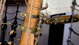
I cut and sanded several, tiny, wooden cleats for the booms, drilled for a tiny brass pin as reinforcement, then glued these into their holes that I drilled into the booms. It took a few attempts because the wood kept breaking when I was close to finishing each one! More Eyebolts, rings etc. I followed the Jenson book to add all the missing U bolts and eyebolts along the cap rails, pin rails and on deck (brass rod), ready for rigging correctly. I cut off the foremast crab-jaws and converted the boom to the gooseneck joint. New brass strip was required to add the mast bands and the foremast gooseneck, plus more bands for the booms and gaffs. I studied the real goose-neck fitting on the internet pictures and planned a method of fabrication. Since I only had thin walled brass tube, I used two sizes of brass tube that fit one inside the other. I fluxed and soldered the end of the tubes to fuse them together and maker a thick-walled tube. I cut thin discs from that , using a Dremel and cut-off disc. After filing smooth, I had several of these discs to make the ends that secure to the mast. soldering one to a second at 90° produced an 'end-cap' that supports the pivot rod and attaches to the mast bands. Two of these with a rod between make up the mast-side part. Then a long section of the twin-walled tubing to slide up and down the rod, with a piece of flat brass bar soldered on, vertically. Filing the brass flat bar round at the rear produced the desired shape for the forward part of the hinge. Soldering the tiny pieces of the gooseneck assembly was very tricky and when the first attempt resulted in misaligned parts, my attempt at heating and adjusting it resulted in solder flowing right through the moving parts and seizing them together, so ruining it. I started again and managed to finally get the parts aligned correctly on version two. With the brass end-cap made and fitted to the fore boom end, the final item slides up and down on the pin and pivots side to side, and the boom tilts up and down. I drilled a hole in the joint for the sail shackle. I had to cut off a wood ring and some tiny fillets from the foremast and fit the bands I made for the gooseneck attachment, and made brass ‘bolts’ (pins, actually, because they are not threaded) to join the bands on the mast. I flattened the end of each pin to look like the actual bolts on thew ship. I also required new brass rod and wire to make many more eyebolts, small and medium, for masts, booms, gaffs, deck and bulwarks. The crosstrees alone required a lot more eyebolts for blocks, lines etc. Also had to make tiny brass rings as miniature shackles on rigging. I glued on small, wooden fairlead blocks to the front edge of the rear cross trees, for the top sail lines (again, not in the kit/plans). I made small brass rings to hang from eyebolts that I made and fitted on the bulwarks, representing the cargo tie-down rings. Drilling tiny holes in stanchions for the eyebolts was difficult at this stage because of all the structures and rigging already in place. Port Stbd Next...Top Shrouds and stays.


-
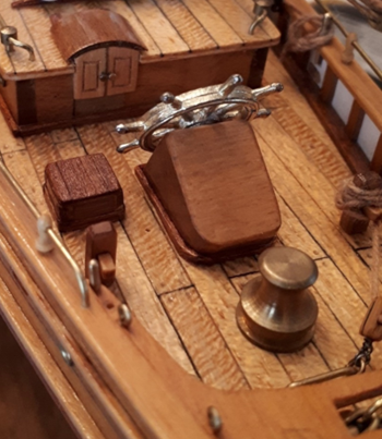
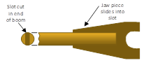
Next, Boom Buffers. Of course the AL kit had no such thing but I just had to ad them. I made up the two (missing) boom buffers from brass rod and tube and wound thick black thread around (super-glued) to look like rubber rings. I made up brass bails and pinned these into the sliding tubes using clipped down brass nails from the kit and I linked the bails together in one ring where the block attaches. I drilled two holes in the front of the after-deck and glued the buffer there, then made up the fore boom-buffer cover. I made a mounting board for the aft buffer, which then slipped under the rear deck cover and glued in place, pitched up at the rear, representing the sloping transom of the real ship. The rings protrude from the slots in the covers and a block attaches easily by hook. Much better than the plan’s simple twisted wire reaching through from a deck eyebolt through that slot to a block. Also, I made up the sheet block travellers (horses?) on the deck, from brass rod (yet another omission from the kit/plans). One here and one for the jumbo jib-sail sheet-block. I carefully removed the kit’s boom supports (they were totally incorrect for the ship) and carefully carved out slots in the deck for the fore boom and main boom crutches. This was very dangerous with all the rigging and structures in the way, so I worked slowly, taking hours, using an Xacto knife with #11 blade. I made the boom crutches from left-over walnut strip, two pieces glued together to make them wider at the top, then sanded to shape. Booms and Gaffs Next, I removed the booms and gaffs, one by one, and remade them properly. I cut slots into the crab-jaws and made clappers to fit. Drilled tiny holes into the sides of the jaws to fit brass rods as hinges for the clappers and to represent the securing holes in the real ship’s booms and gaffs. I removed from the booms the badly placed eyebolts that I had installed when following the kit’s instructions and plans, then put eyebolts in the correct locations, adding a thin brass strip as reinforcement across two of the jaw eyebolts, as per the Jenson drawings. I made the tiny ‘dog-bone’ links on the booms and the 'heart-shaped iron' and 'spectacle-iron' from thin brass rod. I had discovered by now, after poring over hundreds of online pictures, that the sail front corners are held to the booms by shackles to eyebolts. had wondered about that, so I planned ahead and added small eyebolts near the jaws, for the sail cringles. Main boom Jaws Fore Gaff jaws I had tried to use up all existing leftover brass strips of the kit for fittings, but by now they had all been used up, so I had to buy new strips and rods. That was my first experience on this forum, where good members explained why it was so difficult to get brass strip at the time and they gave some suggestions as to where to look. (Thanks again). I finally found some brass material and used new brass rod and strip to make special hooped bales for the boom sheet blocks to ride on. I made boom clamps and rings for hooking the boom tackles and made clamp-bands for the boom lift attachments, adding bent brass rings into the clamp joints to simulate the bent shackles for boom topping lifts. I cut and glued two blocks together then carved and sanded to make a triple block for the main sheet instead of the double that AL made me put on. Also made one for the foremast throat halyard. I drilled holes then carved slots to represent the pulleys inside the booms. I made tiny, thin, brass cover plates to glue on the sides of the booms where the pulleys would be contained. main boom end Jumbo boom I added downhaul ropes through gaff end holes and corrected the badly designed clew line pulley attachments for the kit’s gaffs. I made the blocks on the gaff smaller, in keeping with the real ship. I also added small eyebolts along the main boom, to represent the fairleads for the end lift line, then added brass pins to the boom jaws, to belay the end lift line. I drilled the booms for end lifts where required continued...
-
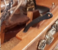
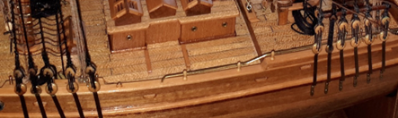
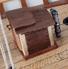
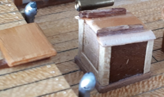
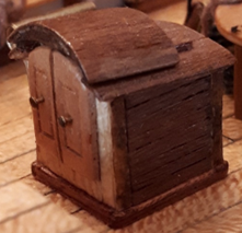
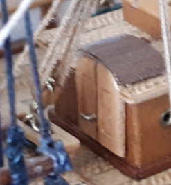
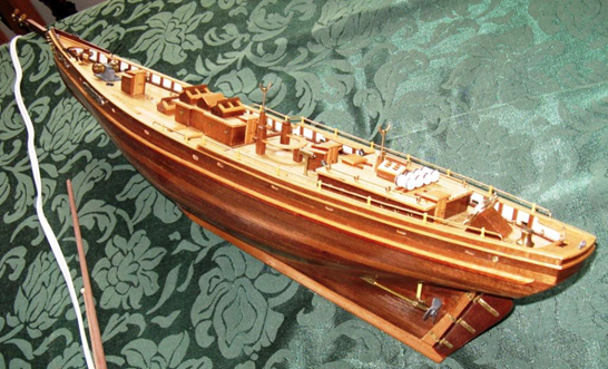
REFIT Ratlines The first task in the refit was to correct the shrouds and ratlines. The AL plans showed all of the shrouds covered in ratlines, which is incorrect, so I had to cut and remake the ratlines several times and modify the shrouds. I compromised on the main mast, to achieve a better scale-like appearance of the ratlines while trying not to remove the entire sets of shrouds, ratlines etc. However, I was frustrated because I discovered that the plans also had shroud lines going to the wrong places, with the spreader shrouds all wrong, and even the deadeyes were in the wrong locations (too far aft). I cut off and remade ratlines several times and remade the deadeye reeving, making the shrouds taught this time, but while trying to cut off the super-glued ratline knots, I accidentally cut some foremast shrouds. There was no way to fix that so I had to start again on those! I cut off the foremast shrouds completely and those ‘mobile backstays’ that I had just made up, because they were wrong. I knew by now that the deadeyes and shrouds were in the wrong places and too far to the rear, but I couldn’t remove the chainplates without damaging the hull, so I just bent all of the chainplates with deadeyes forward, to bring them much closer to the correct locations, starting just forward of the masts. Unfortunately, I couldn’t really move the nicely finished pin rails to match the new shroud locations, so that was a compromise. Then I made new shrouds in the correct positions, ignoring the plans, and tried to make them more taught this time, pulling the mast tops over with one side then pulling them back vertical with the other side. I finally arrived at a repeatable method for the deadeye lanyards. I cut 20 to 21 cm of lanyard to allow reeving and tying. Blackened the pink thread with sharpie permanent marker. Knotted one end and put a dab of cyano to secure the knot. Waxed only 10 to 11 cm from the knot so the line had a clean end for tying and gluing. I substituted small deadeyes for the second deadeyes from the front, as per the Jenson book and ran the topmast spreader-shrouds down to these. I kept these outside the other shrouds and not tied to the rod like the other shrouds. I ran the remaining shrouds to the correct locations too. By the time I reached the last few deadeyes on the foremast I even tried tapering the upper deadeyes to look like the pear-shaped real versions rather than the kit’s round items. I then made the correct ratlines on the new foremast shrouds. The main mast shrouds were an acceptable compromise after some modifications, so I did not remake those completely. The ’futtock’ shrouds of the kit were wrong (there should be metal futtock rods) but that was too much to change after all the work I had done so far; I couldn’t bear it. I made some brass rods into my first attempt at a bail for the foremast, to attach the new jibstay instead of it simply looping around the mast! I flattened the ends and drilled holes for the pivot pins (brass nails from the kit) and for the front ‘bolt’, representing a shackle. The wooden mast bands from the kit were rectangular, unlike the curved shape of the real ship, so I sanded them to a curved shape then re-varnished them. Here you can see where I had removed the eyebolt for the jib sail halyard block and positioned it lower, several times, trying to align the block with the stay sail now that I had the fore stay held to a bail. (Later, I removed it altogether because the real ship simply does not have a block attached there!) Deck structures The kit’s simple, square, flat companionways were just not good enough; nothing like the Jenson book’s drawings. Oddly, the kit’s box-top photo shows curved roofs on the companionways yet the instructions and plans show flat roofs; simple plywood plates from the kit. So, starting at the front companionway, I cut off the doors and hatch and built up the companionway roof into a hump with several layers of the thin, walnut planks that were left over in the kit for outer planking of the hull I cut the planks to fit around the hatch rails. Sanded the planks down to produce a curved roof. Then I converted the flat, plywood hatch to a curved hatch, building up layers of the thin, walnut planks. Carved out the inside of the hatch to clear the companionway roof and carved rail recesses. Then glued the hatch to the rails. Then I made new doors from a single piece of smooth, thin plywood, again left over from the kit. I made the new doors shorter, because the kit had flat ply doors right down to the deck whereas the real ship has short doors, mounted well above the deck to prevent seawater running down the companionway! I curved the top of the door panel to match the new hatch and cut a rebate down the centre of the door panel, where I inlaid a thin strip of walnut to indicate the join of the two doors. Then I made parallel cuts around the outline of each door and carefully removed the wood between the lines. I ran the curved edge of my small tweezers around the resulting slots to round out one edge of the slots. This gave the appearance of a carved door panel recess. Varnished the door to finish it. I used more thin plank material to fit vertical edge strips on the companionway corners, then glued thin planks of walnut around the walls, between the corner pieces. Finally, I glued the new doors. Then I made tiny deck coaming strips and glued these around the base of the companionway. Varnished it all. It looked completely different and much more scale like. I later stained the corner edges. I continued aft, doing this to all companionways, doors and hatches. The doors and hatches became better with practice, as I worked rearwards. For one door set, the Jenson book shows a lever, so I made brass rod into a lever handle instead of the simple nail head of the kit. Here is the rear companionway, just ahead of the main cabin doors, midway through the refit Note the old, flat hatch on the main cabin roof to the left, and the coaming now around the companionway, plus vertical corner strips going on, before the solid walnut cube is covered with tiny planks Then here it is completed, with curved, planked hatch, carved door panels and each set of doors has its own type of handles, like the Jenson drawings show. I realised the kit’s aft deck and main cabin were too short and its vertical transom was wrong but there was nothing I could do for those now. However, I did make up the square hatch cover/seat to the port side of the helm and made up the two quarter bitts, ready for the main sheet to belay. I also made and fitted coaming around all other deck buildings and the helm’s steering gear box. I also twisted out all of the brass deck cleats and eyebolt/rings that AL made me put in; those were all incorrect. I cut/sanded down the protruding wooden top rails of the skylights and re-varnished them. The AL kit had instructed to glue these rails on top and they stood up above the skylight panels like pronounced ridges. The actual ship has no such thing; its skylight roof panels meet at the top; no ridge!
-
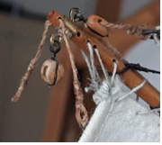
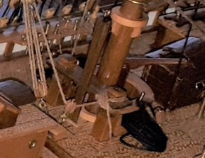
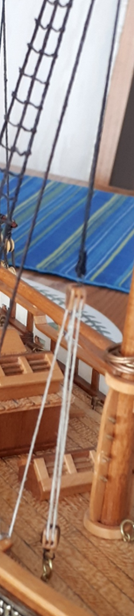
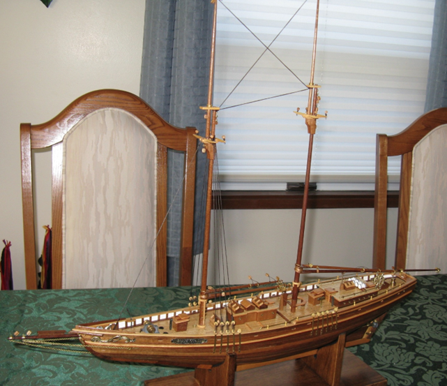
2011. I worked on the booms and gaffs, then standing rigging – shrouds, most of the ratlines according to plans and instructions. The ratlines were proving tedious with so many tiny knots to make. The booms and gaffs on this kit were made by tapering the wood dowels (the kit plans show too much taper, but I didn’t know it was wrong). The jaws were of thin plywood and I had to cut a slot in the end of each boom and gaff then gradually make it wider until the jaws slid inside nicely, then glue it. The jaws were held around the masts by brass wire bent into rings with right-angle bends at the ends, to fit down into the holes in the jaws. The ratlines were driving me crazy, so I put the ship on top of our TV/ entertainment centre, near the end of 2011. I was quite pleased with what I had accomplished. The ship sat there for some years- attractive to look at but begging to be finished. Refit and running rigging Dec 2021 Covid had shut down the work I was doing so I was suddenly retired. I recommenced work on the ship, after it had sat since 2011. I thought I had only to finish the top ratlines and do the sails and running rigging After finishing the ratlines to the plans, I figured out how the sails were to be done according to the plans. As the AL instructions said, “Now at this point, if you are lucky enough to have some friendly female assistance at hand with a sewing machine, so much the better”. I got a very unimpressed look when I read that out to my wife! However, after laughing, she did plan and then began sewing up the sails for me — a great job too! I then began the rigging, starting with the ‘mobile backstays’ as the AL instructions described them. (See picture here; the tackle with white thread!) When I finished these, the positions didn’t make sense to me for a working sailing ship and the white line provided in the kit didn’t look right. Also, the top mast stays from mast top downwards through the spreaders seemed to be in the wrong position (They were!). That was when I began asking questions about the logic of the AL rigging and I began looking through the new Jenson book that my wife had bought for me a few years before. Alarmed at how different (and wrong) the AL plans were, I looked on the internet for pictures and also found the Bluenose II website with its virtual tour. Most of this material did not exist when I began making this model. In fact, the internet was only in its infancy back then and most people didn’t have it, including me, so I was surprised as to what was there on the web now. It was apparent that the AL plans and kit were very much simplified and totally incorrect if you wanted to make a scale-like Bluenose II. I was not happy, so I explored the impact of possible changes. It was already too late to change the hull and deck, or the bulk of the deck fittings, as I could not detach the super-glued winch and buildings. I would have liked to have improved the winch and moved it back towards the companionway, as it is shown in the Jenson book; also, I would have liked to have had the proper sloping stern all the way up past the deck, instead of the flat, vertical transom in the kit. The bulwarks probably should have been a bit taller as well, and there should have been a continuous sub-rail under the top rail on the aft deck, with the pin rail built into that, instead of the top rail as AL made be build. Also, AL’s kit had too few stanchions and only a few scuppers. Oh well, for the rest I believed I could do better, and I just couldn’t leave it as it was, so a refit commenced! see following post.
-
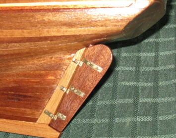
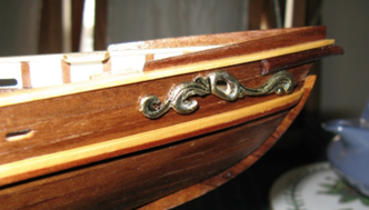
After fitting the stanchions, I then began work on the rudder/hinges. I worked carefully to keep the fit tight but free moving and kepp all hinges in alignment. By June I was on the cap rails, pin racks etc., following the plans. The front ‘trail boards’ then went on, followed by the ‘bulwark rails’, ‘pin racks’, ‘taffrails’, ‘topgallant and stern topgallant’ rails then the ‘wales’ and the ‘prow reinforcements’ (AL terminology). I then varnished the entire ship; that brought out the lovely colours of the different woods. I had already decided to keep the ship in natural wood finish to see the beauty of the ship, rather than paint my hull. I cut the scuppers according to the plans and with the bottom of the holes just at the waterway height. With the hull already varnished it was a tougher material, so less worry about splitting as I drilled and cut the scuppers. My x-acto tool kit was very valuable throughout all of this. I now know that the real ship has far more scuppers than this, but in 2008 I just followed the plans, which showed these few holes. I made a rudder shaft stub and added this to the rudder, to protrude into hull, then I made a hole in the hull for this. This looks much better than the original kit's loose rudder hanging there with no connection through the hull. Then came the cast scrollwork piece at the bow. I must say this was nicely made by AL. By 2009 I had the deck structures that I had built all glued on with cyano. At that time, I was still following the plans/instructions. For the window bars on the skylights, I cut and filed some of the provided brass rod to size. I made tiny holes for the bars in the frame sides then I inserted one end of a rod into a hole, pushing it in until the other end would fit into the frame then slid the bar back into that second hole. When all bars were in, I added a drop of cyano glue to each one. The plans showed the bars horizontal, which is incorrect, but I didn’t know at that time and it’s too late to change it now. The brass safety rails and their stanchions also went on, and the propellers with their mounts. Those propeller shafts were tricky to establish the correct angles on the brass plates and the correct locations for the holes in the hull. The bowsprit parts went on too. By mid 2010 I had put on the masts and also made a proper stand/cradle and stained it. Next post is at 2011.
- 15 replies
-
- 1
-
-
- Bluenose II
- Artesania Latina
- (and 1 more)
-
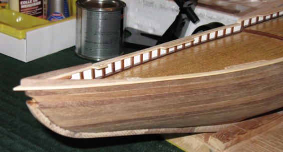
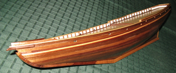
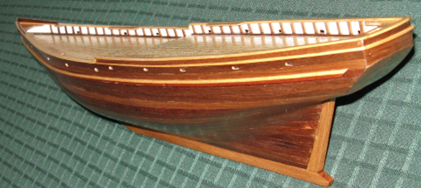
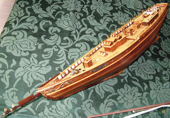
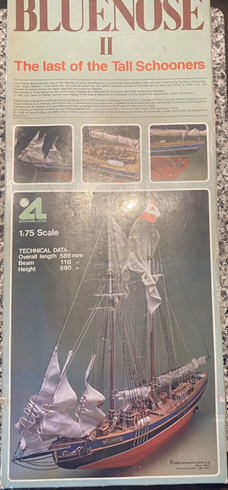
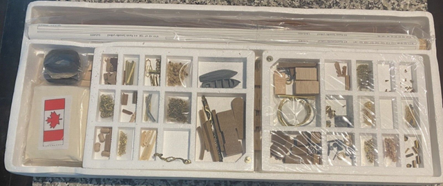
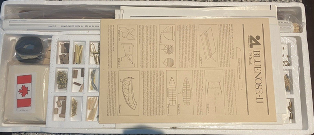
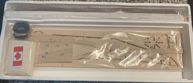
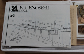
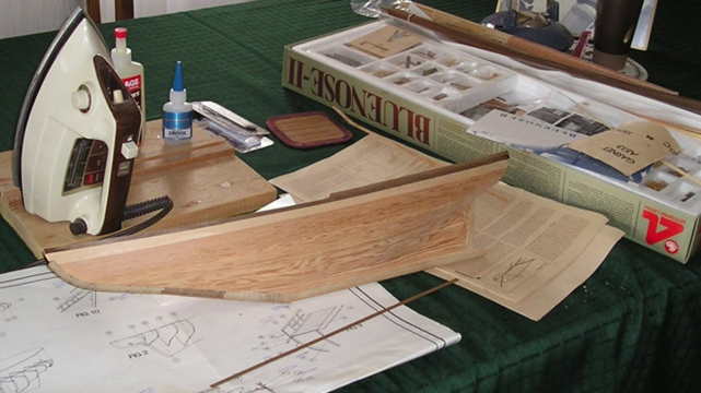
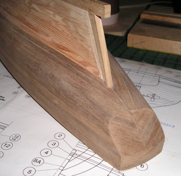
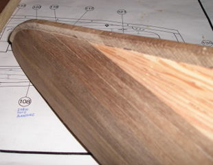
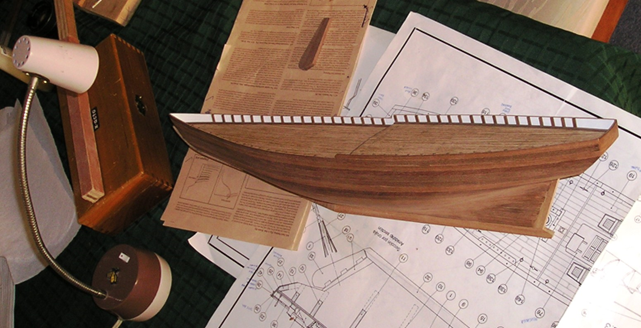
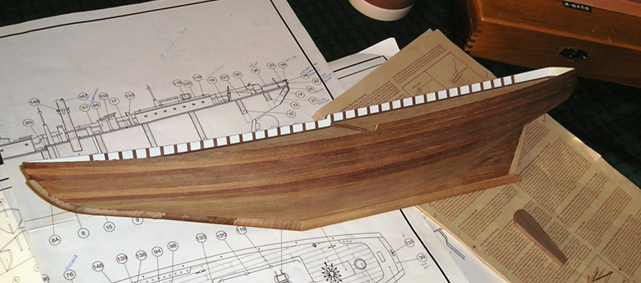
This has been a long term build. I had never built one before. I hesitated to post this build log because I am nearly finished but I have received help from other members here, so I thought my experiences may be of help to others. I tried to document my progress to an extent through the years it took and will post it here as I am nearing completion. Artesania Latina # 20500 Bluenose-II This kit was bought around 1986 from Hobbycraft Canada of Toronto. It was a gift from my wife to her Dad but was left untouched by her Dad until given to me in the summer of 1996. It was like this…. ... and under those trays... A glimpse of one plan sheet is shown here, too. I started looking at the kit and its VHS video cassette (“You Take the Helm”) in November 17th 1996 -. I began construction the following week. The VHS video was by Model Expo and shows model-maker Frank Mastini building the kit. His kit does not have the foam boxes though; rather it has the parts in plastic bags attached to paper sheets. Some of the advice in the video was useful in the beginning but as time went on and my experience grew, I ignored it and followed my own ideas. December 1996: With the hull frames assembled, adjusted, glued and trimmed to plans, I pinned the deck plywood onto the frames, using a tiny hammer for the brass nails. Then I started cutting planks for the deck. I laid black cotton between each plank and their ends to simulate caulking; the cotton set into the white glue nicely. I drilled 'nail holes' at each end then put a dab of glue into the holes and gently sanded over, to fill the holes and represent the wooden plugs of the real ship. 1997 Jan: Deck planks were finished; I began the first layer planking of the hull but by March 30th had to leave it for everyday life issues and by 1998 I had started night computer courses, to retrain. 2000 January 18th; my journal says I started again; heating & bending hull planks, using our old laundry flat iron. I finished the first planking by the 30th and had it all sanded nice and smooth, then couldn’t see how to fit the bulwarks. They seemed to be not long enough or tall enough so wouldn’t join at the front and I didn’t know how they should line up at the back. I rang a model shop about it then began doing the deck structures. By March I had fitted the bulwarks then transom, but then summer garden work took all my time. Then life became busier again with my night school studies. I had bought a computer by now to use for the studies and these carried on all the way through to 2005 to get a software development diploma. Feb 17 2008. I started the ship again, doing the second planking with walnut veneer planks. This picture shows two rows of walnut planks, starting at the caprail position, as per the AL instructions. I had a digital camera by then! March 2008: In the following picture, the walnut outer planking is on, down to where the planks wrap around under the hull, and the stern badge and transom are also planked. You can see where I had sanded the first planking and false keel down towards the stern post, to ensure the second planks will lie flush with the post. At the prow, with the planks cut to fit tightly against the keel. Finished them by the end of March. April- I bent the waterways to shape by wetting and steaming with an iron, then cut to final length and glued onto the deck around the bulwarks. Then I cut the stanchions and fitted them to the bulwarks (now painted white inside) by May. Next post I will continue with the rudder.
- 15 replies
-
- 1
-
-
- Bluenose II
- Artesania Latina
- (and 1 more)
-
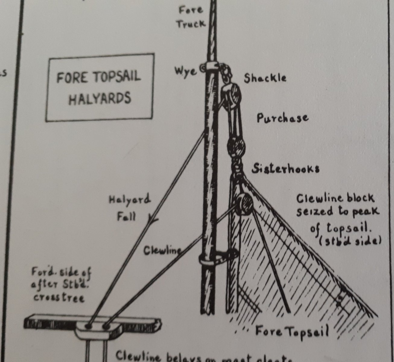
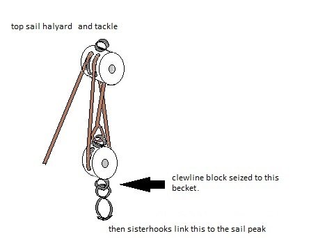
Thanks wefalck. That's what I was thinking. I also just received a reply from Captain Watson of the current Bluenose II and he says that rigging has changed a bit through the years and he explains this is currently how the Bluenose II is rigged: "The clew line block is simply seized with small line to the starboard side, on the becket on the lower portion of the single halyard block at the head of the sail. This is where the sister hooks attach the sail to the halyard. The clew line leads from deck through a fairlead attached to the middle of the forward side, of the aft spreader, through the clew line block (leading forward aft), through a grommet in the middle of the sail and then to the clew. When the clew line is pulled, the clew is pulled to the sail grommet, then both to the head and all of it is pulled to the head of the lower mast where the hoops on the topmast come to rest when the sail is in the lowered condition. This means that the head, the mid sail grommet and the clew are all together at the lower mast cap. It should be noted that the grommet arrangement has changed over the years and on different schooners. The single grommet in the middle of the sail is what we use now. " * So it seems the Bluenose II crew now seize the block to the lower becket of the halyard's single block, so the clew line load is taken up directly through the tackle to the mast, rather than pull on the sail's peak grommet. See attached drawing. With this in mind, looking at the Jensen drawing again, it now looks to me like the block's strop/eye may have been taken to the sister hooks at that time when the book was created; again the load would have been taken directly up to the mast and not through the sail's grommet. It is also possible that the Jensen drawing is depicting the very same method that you describe. It's a pity that Jensen did not write the exact method or draw it in close-up . I think I will amalgamate all this information and form an eye then attach it to the sister hooks. I doubt anyone will ever notice the detail but me. Thanks to all who contributed here!
-
Thanks, Allanyed. Hmm, I'm curious about this. I might just email the Bluenose II team and ask the captain about it. They are quite helpful there. I'll let you know.
-
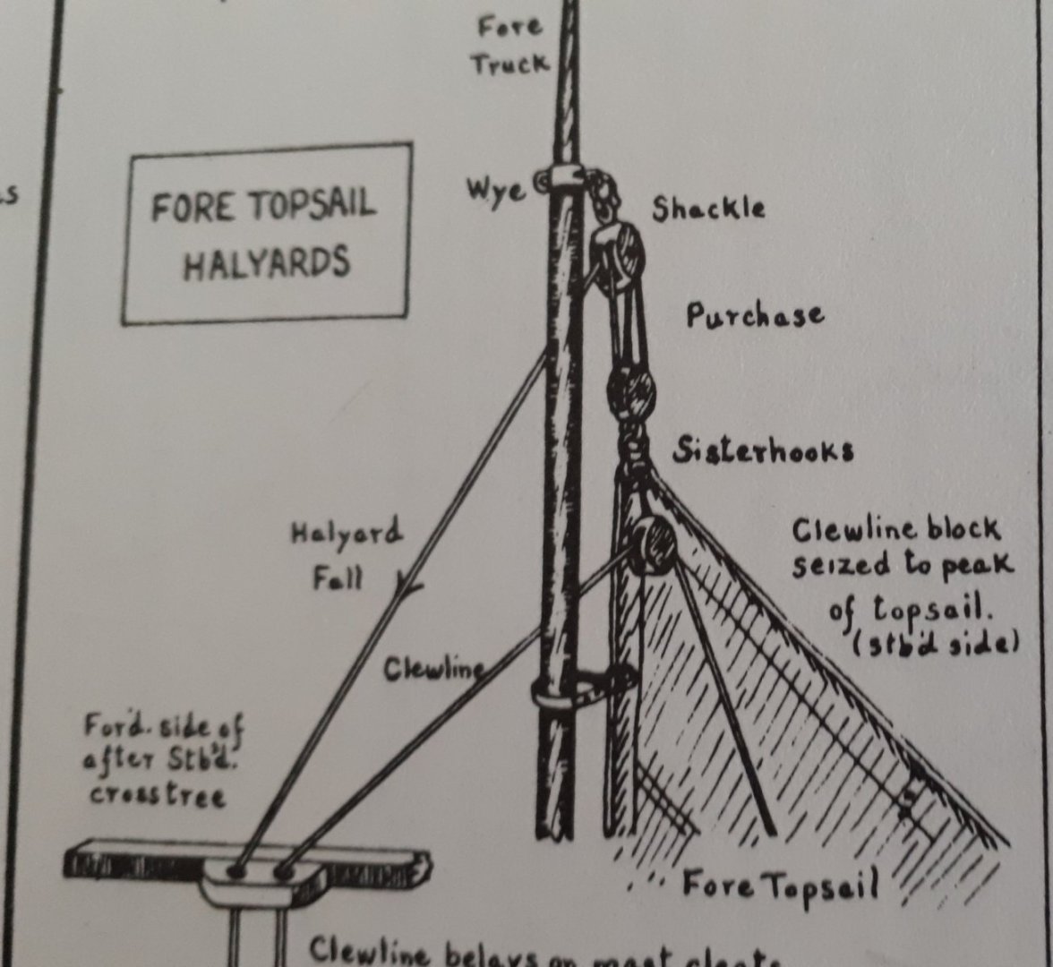
I'm rigging a Bluenose 2 from an old Artesania Latina kit. I'm following the Jensen book for my rigging and the top sail page says the clew line block is seized to the peak of the sail. The drawing looks like the block hangs from the centre of the peak cringle, but I can't see enough detail. See attached snippet from the Jensen book. I have a block stropped with line, but do I simply feed the line through the peak cringle and bring it around the edge of the sail then seize the end to the line, as when I make a simulated 'spliced eye'? That is what I did with the down-hauls on the jib sails, because Jensen said the top of the down-hauls were spliced eyes through the peaks. Or do I bring that line around and tie it (doesn't seem right). Or am I supposed to sew the line onto the sail, just next to the peak grommet? I am tending to the first option, but I cannot find any reference and drawing on the internet.
-
Can't Find Thin Brass Strips
Yorky1 replied to mikiek's topic in Metal Work, Soldering and Metal Fittings
Hi Marcus, Thanks, your experience of this method is the best proof 🙂. If it works for you then this is a good idea for me to try next time. Cheers. -
Can't Find Thin Brass Strips
Yorky1 replied to mikiek's topic in Metal Work, Soldering and Metal Fittings
Well, I ended up getting K&S brass strip and rods from Great Hobbies.com. I got 1/64 x 3/32 strips ( a bit thicker than I thought- I wanted similar strip to the AL Bluenose II kit, but it works- just harder to wrap around into bands etc.) Also got .025" x 1/4 and .032 x 1/4- I made several parts from this, including some parts for the fore boom goose-neck joint. Also got brass rod - .032" (0.81mm) and 1mm. So all those are in stock at Great Hobbies right now. I now have finished my refit/upgrade of the AL Bluenose II kit. Made all the extra eye-bolts required and mast bands, jumbo boom articulated joint, fore boom joint and mast mounting bands, boom buffers and many rings. Now this kit is more like a real ship and feels satisfying. Ready for sails! -
Can't Find Thin Brass Strips
Yorky1 replied to mikiek's topic in Metal Work, Soldering and Metal Fittings
Right, hobbylinc.com: has both sizes listed but out of stock; I asked to be emailed when in stock. onlinemetals.com: only goes down to 1/4" wide and I have no way of cutting strip cleanly. All I can do is to bend a piece of strip back and forth until it breaks there, to get the right length for a part. zoro.com: no results on their search for brass flat bar or brass strip (or flat stock). micromark.com: they call it flat stock, but all too wide (most of their stock is to thick as well). A sku search for K & S 1/64 x 3/32 gave a business called Gwartzman's.com which has it but their shipping makes it about $20 for a couple of dollars of material. Ouch. Mind you the scarcity of this stuff (as mtaylor pointed out) suggests that I should just go ahead and order this. No sign of the 1/8" wide being in stock anywhere but at least the 3/32 will be a reasonable close-to-scale size for most bands I want to make. The table saw looks really nice but I can't justify the cost right now. Thanks again to all of you. -
Can't Find Thin Brass Strips
Yorky1 replied to mikiek's topic in Metal Work, Soldering and Metal Fittings
Thanks for your help chaps! I'll try these ideas and let you know. -
Can't Find Thin Brass Strips
Yorky1 replied to mikiek's topic in Metal Work, Soldering and Metal Fittings
Hello! An old thread I know, but I just registered here and this is exactly what I need to know too. I checked the sites advised in this thread but I found Special Shapes has gone - its web domain is for sale - and the other suggestions either do not have these sizes or some of the links just do not open for me here in Canada. A web search shows me that most places sell only 1/4" strip at the smallest, same for my local hobby store, yet I need both 3mm wide and 2mm wide at about 0.39mm thick. That's what the AL kit (Bluenose II) had originally and I was able to use the spare lengths of those pieces up to now, but now I have run out. These seem to be about the same as the 3/32x1/64 that the original poster needed. I did find these two sizes at a hobby site, by K & S but they say "out of stock" for both sizes. Strangely, I could not find these sizes on K &S's web site. So where can I get these small sizes today? Thanks.