Steve Anderson
-
Posts
51 -
Joined
-
Last visited
1 Follower

Recent Profile Visitors
241 profile views


-
 dafi reacted to a post in a topic:
HMS Victory circa 1765-1791 by Steve Anderson - 1:64 scale
dafi reacted to a post in a topic:
HMS Victory circa 1765-1791 by Steve Anderson - 1:64 scale
-
marsalv reacted to a post in a topic:
HMS Victory circa 1765-1791 by Steve Anderson - 1:64 scale
-
marsalv reacted to a post in a topic:
HMS Victory circa 1765-1791 by Steve Anderson - 1:64 scale
-
garyshipwright reacted to a post in a topic:
HMS Victory circa 1765-1791 by Steve Anderson - 1:64 scale
-
CiscoH reacted to a post in a topic:
HMS Victory circa 1765-1791 by Steve Anderson - 1:64 scale
-
Martes reacted to a post in a topic:
HMS Victory circa 1765-1791 by Steve Anderson - 1:64 scale
-
druxey reacted to a post in a topic:
HMS Victory circa 1765-1791 by Steve Anderson - 1:64 scale
-
BLACK VIKING reacted to a post in a topic:
HMS Victory circa 1765-1791 by Steve Anderson - 1:64 scale
-
 ccoyle reacted to a post in a topic:
HMS Victory circa 1765-1791 by Steve Anderson - 1:64 scale
ccoyle reacted to a post in a topic:
HMS Victory circa 1765-1791 by Steve Anderson - 1:64 scale
-
GrandpaPhil reacted to a post in a topic:
HMS Victory circa 1765-1791 by Steve Anderson - 1:64 scale
-
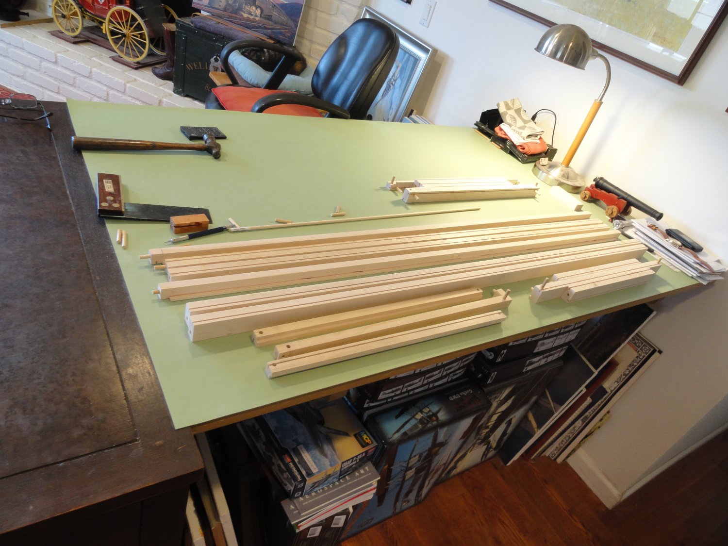
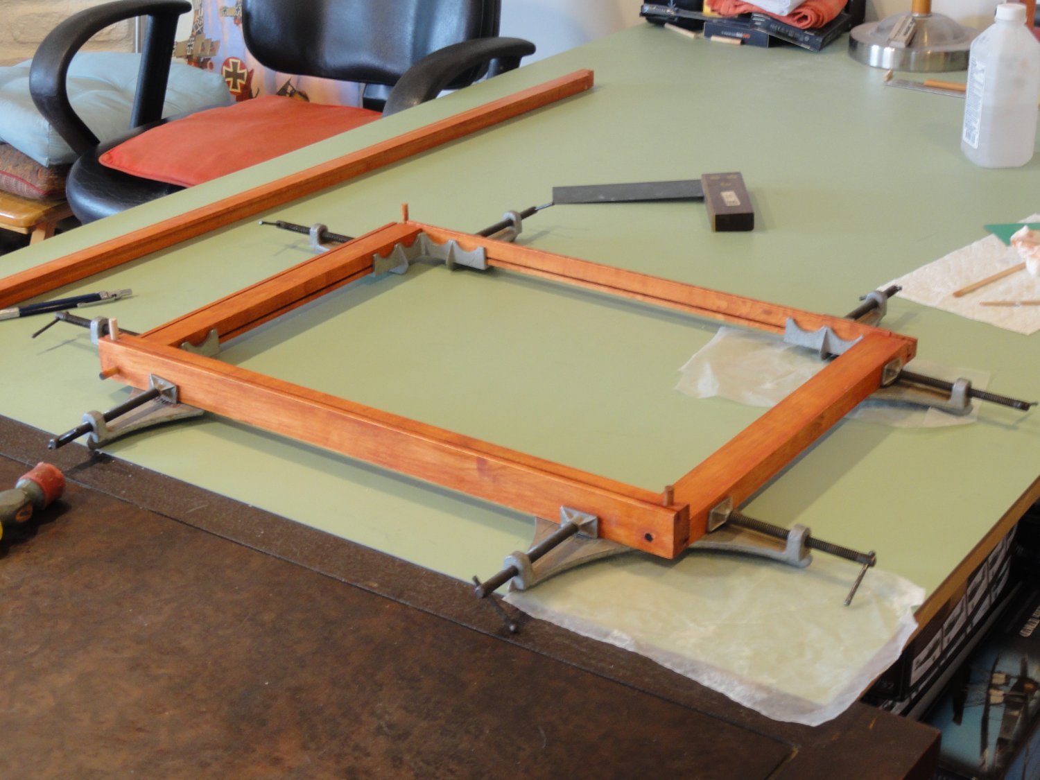
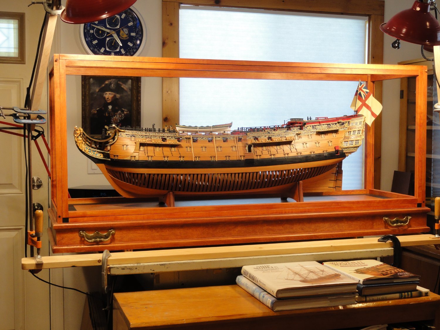
 Part 12 The Case of the Case In the latter part of October, 2022, I drew up plans for the display case that would protect Victory from dust, cats, and the few individuals that can't resist touching something. I did this "Old School", something I really enjoy, with drafting tools and a mechanical pencil on my drafting table. Dimentions of the base are 54 1/2" L x 17 5/8" W x 3 1/2" T. The case frame for the plex is 53" L x 16" x 21" T. I chose Maple for the material and Minwax "Gunstock" for the stain. I've built smaller cases before and a few furniture pieces. I estimated about a month to do this. Then the rains came through the Central Coast of California. To be continued.


-
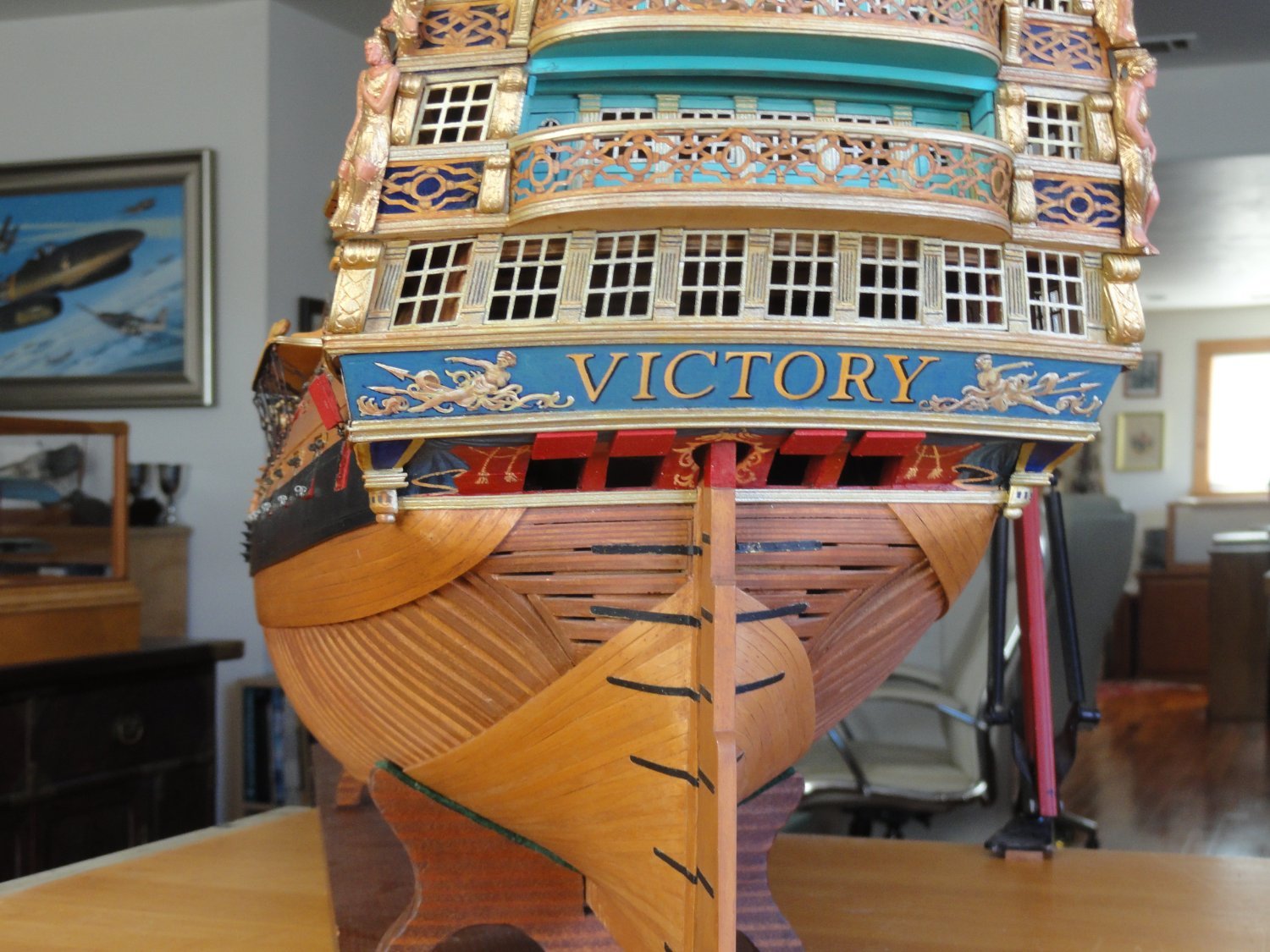
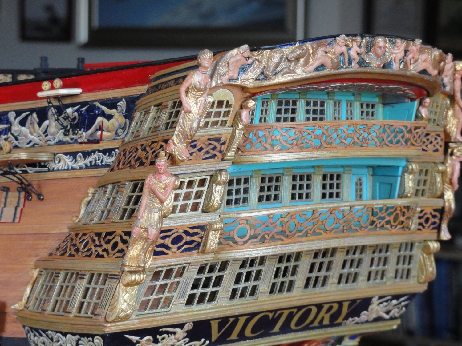
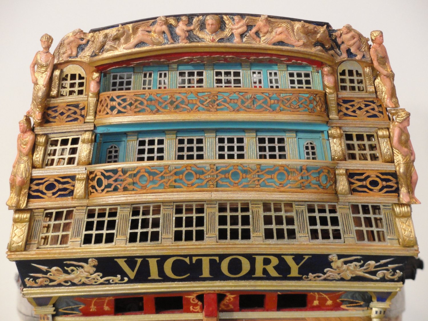
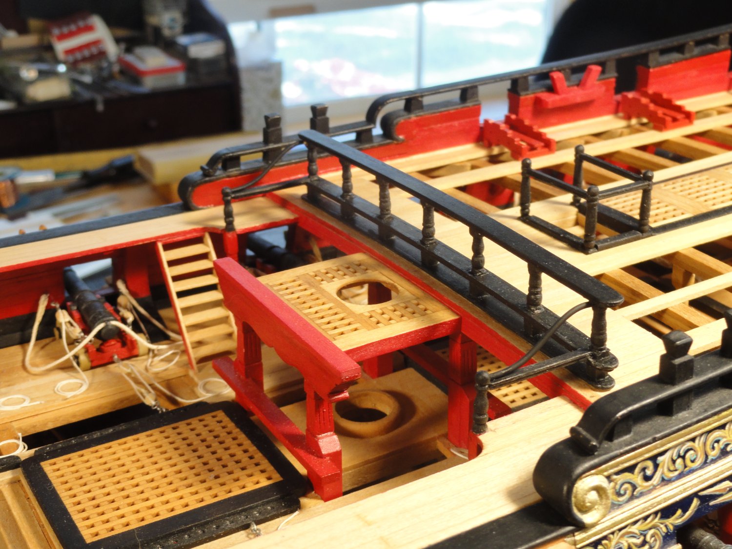
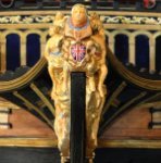
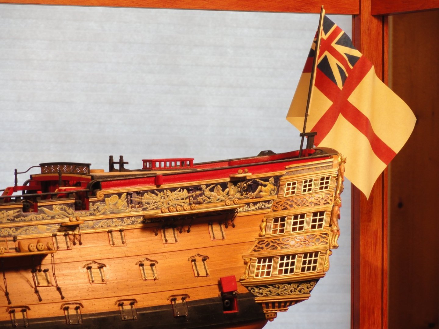
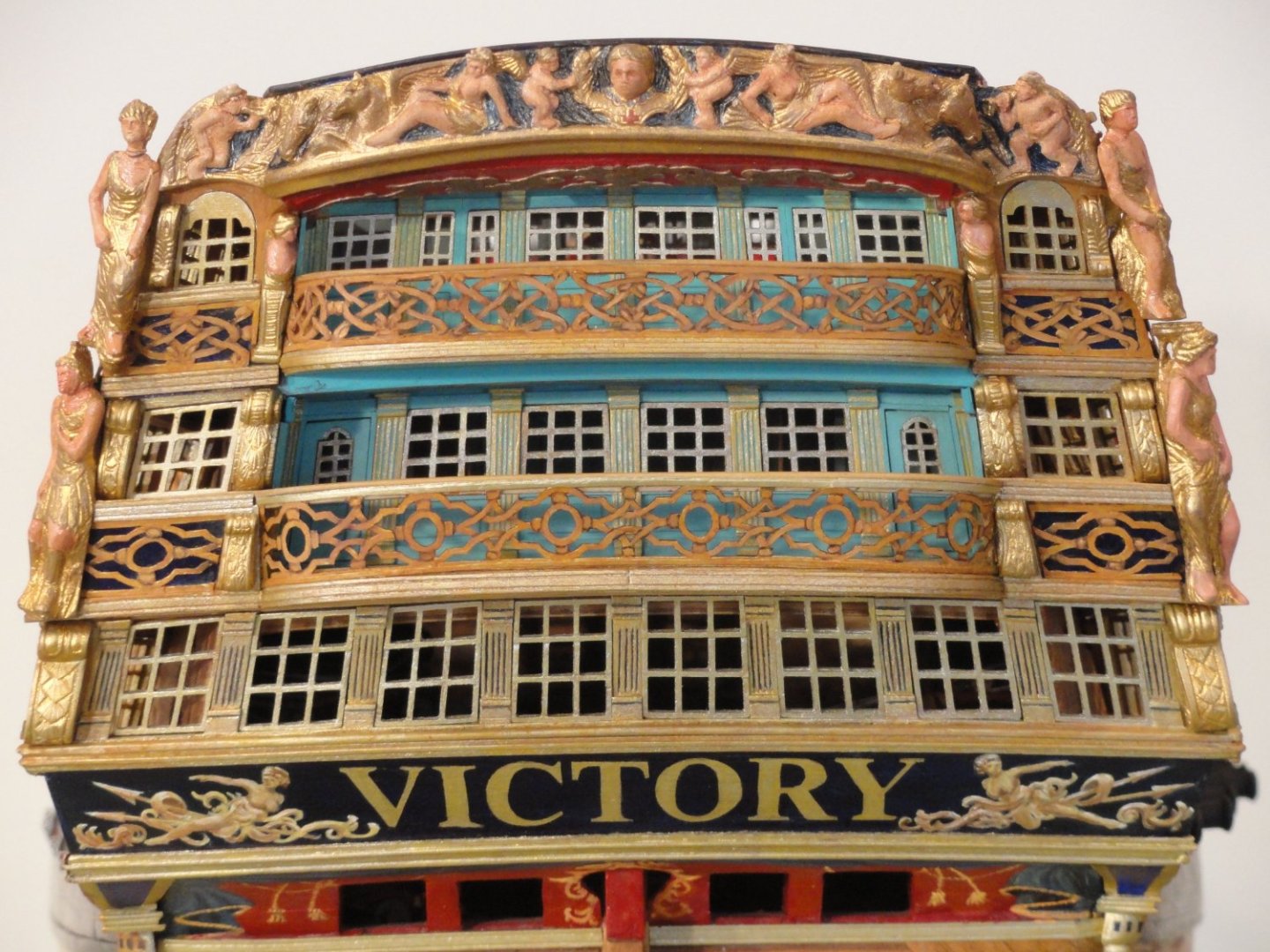
The cap rail installed on the gangway railing. Druxey kindly pointed out to me that I had used New Times Bold type face for the VICTORY letters. This reqired a repainting of the counter, which I'm much happier with. So, along comes a unexpected fun detail that adds so much. While fabricating the ensign fixture and staff I decided to make the ensign. I did this using Photoshop. Just adds an extra magesty to the ship. One of the last extra finishing touches was I went over the hand cut balistrades airbrushed in gold leaf and with a small brush over painted, glazed burnt umber washes to give a 3D woven look that is seen in the 1765 model. Tedious but was all done in a day. Victory was now finished to where I wanted it to be my the end of October, 2022. She was now ready for a museum quality case. Next in Part 12 The Case of the Case


-
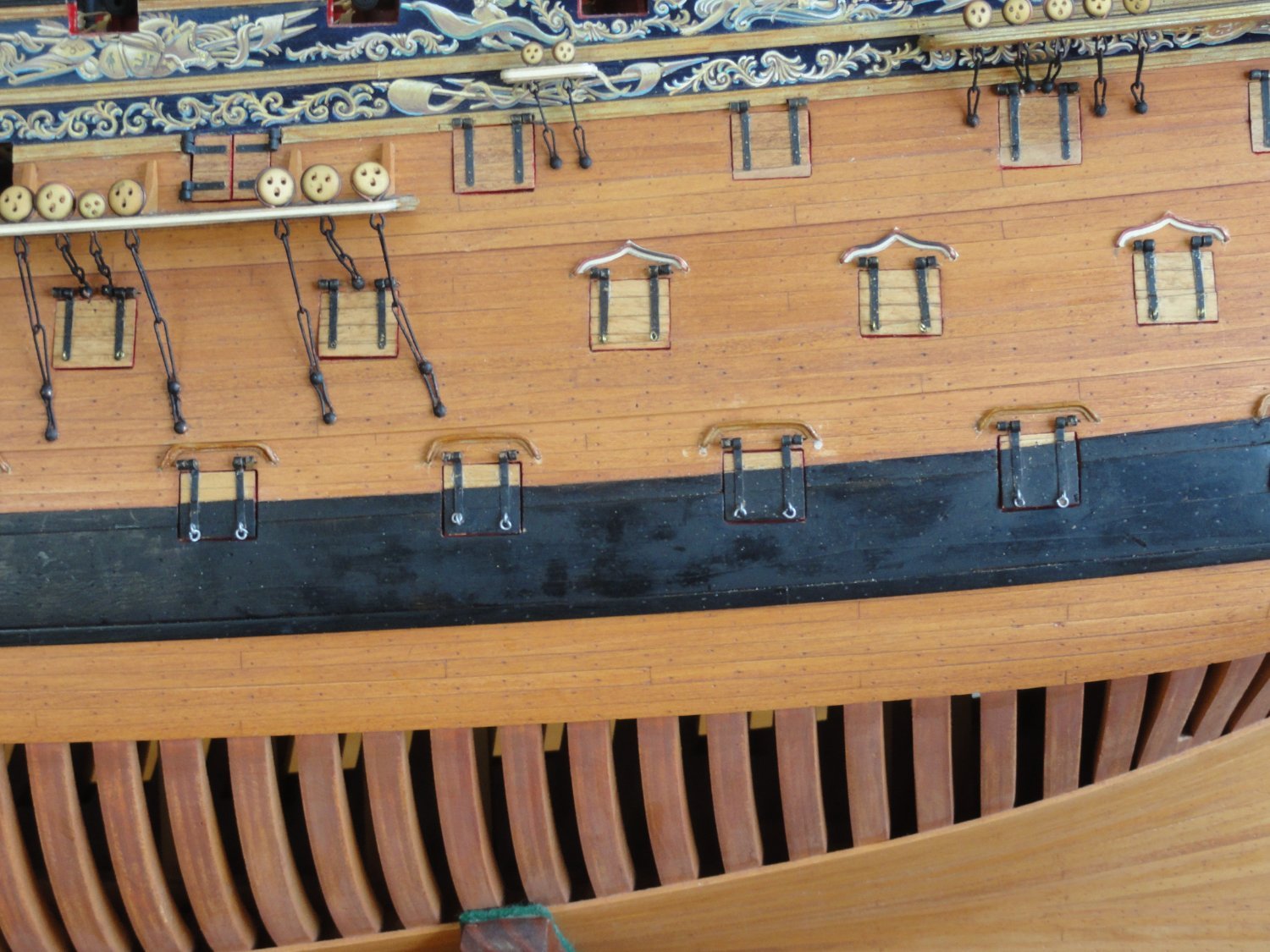
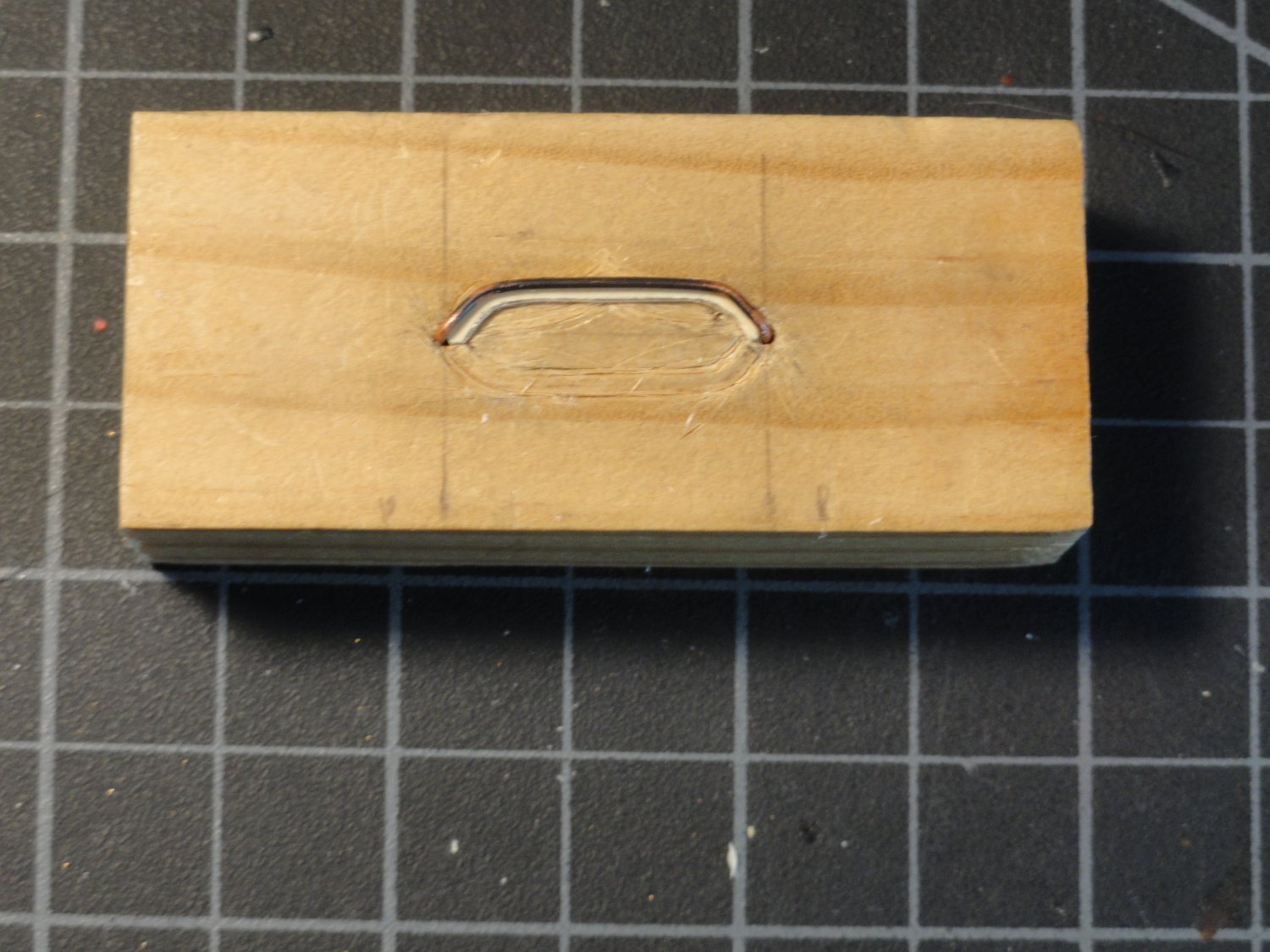
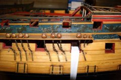
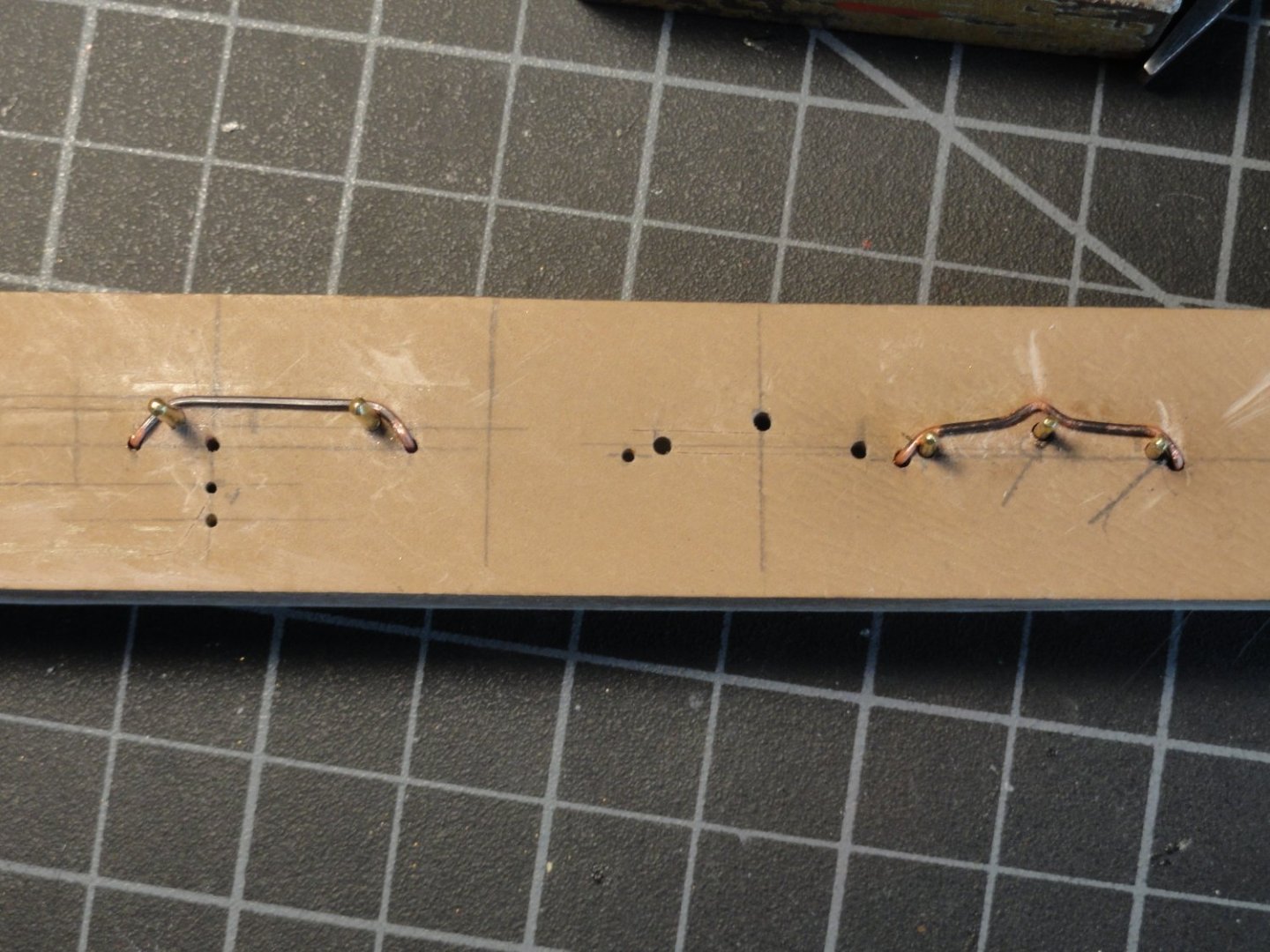
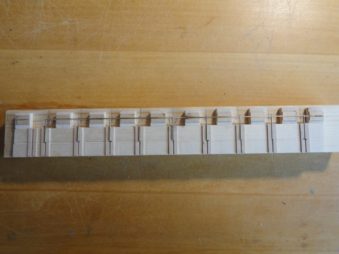
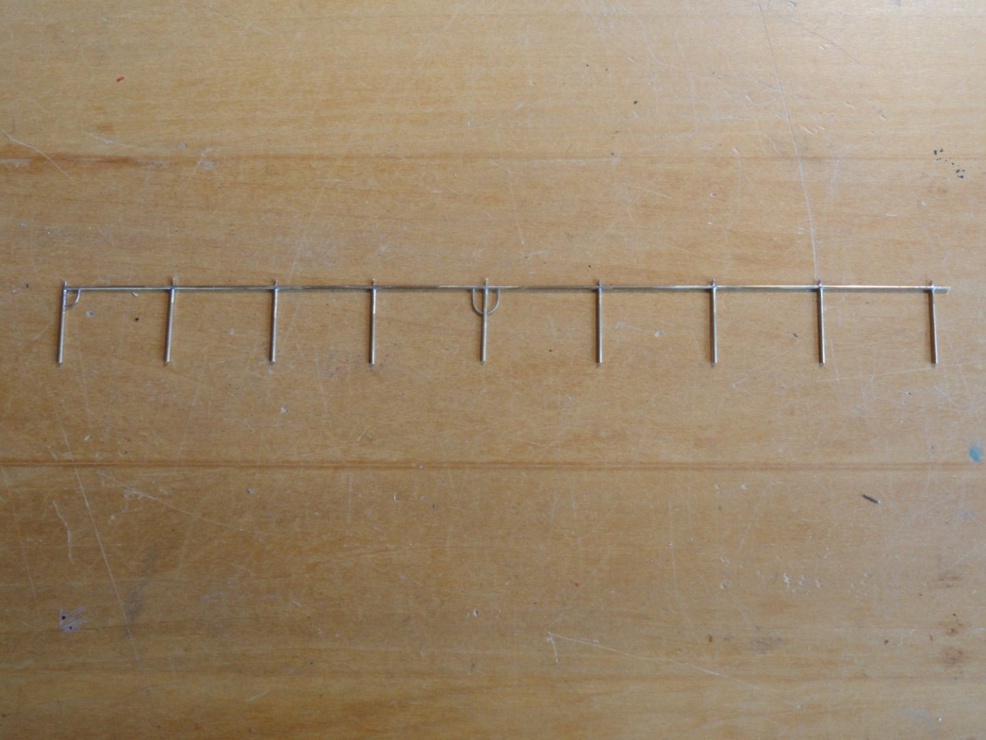
Part 11 Road to completion It has been a long, long road. After a two year break (October 2020 to October 2022) from painting to finish Victory. Here's the last few details. Another one of those mini projects that was set aside was how to make rigols. Using 20 guage copper wire, anealed over the gas stove, I drilled holes in a wood block to install brass pins for shaping. Small pieces of manela file folder stock were glued underneath and cut to shape useing an X-acto knife. Drilled holes in the hull to press fit the finished rigol. Bingo. Problem solved. Next came the gangway rails. Photos explain.


-
Really nicely done Dave. Very informative. I have a 40 year old J Class fiberglass hull on one of my work tables. 36" LOA, 1:43 scale. Given to me a few weeks ago by my best friend. He just discovered he had it a couple of months ago. While we all think we have too much stuff, he has two cargo containers on his property for the overflow.
- 31 replies
-
- 1
-
-
- Shamrock V
- Amati
- (and 2 more)
-
Steve Anderson reacted to a post in a topic:
Shamrock V by David Lester - FINISHED - Amati - 1:80 - J Class Yacht
-
Christian... Thank you very much. "A model of one of of the most famous ships in her original (as far as we know today) appearance." Pretty good summation. Albert...Thanks. Allan...Thank you for kind compliments and the Bloomfield/Armstrong question. I could go with Johnny's answer above, "Hmmmm, 78 ... 87 ... could be lysdexia. (dyslexia 😉 )", but I won't. In Brian Lavery's book, " Nelson's Navy", both types, page 82, are discussed. Frankly I chose the Bloomfield pattern due its cleaner design and the button loop. The loop ensures the breaching rope will never flip off the button for however many decades the ship will last. In the '90s there was next to nothing available on the 1765 -1800 version of Victory. All I was able to find for Bloomfield was "late 18th Century", which fit the window. I think I'm going to have to stretch my span of years in the title. Thanks for the info. Cheers, Steve
-
 Steve Anderson reacted to a post in a topic:
HMS Victory circa 1765-1791 by Steve Anderson - 1:64 scale
Steve Anderson reacted to a post in a topic:
HMS Victory circa 1765-1791 by Steve Anderson - 1:64 scale
-
Steve Anderson reacted to a post in a topic:
HMS Victory circa 1765-1791 by Steve Anderson - 1:64 scale
-
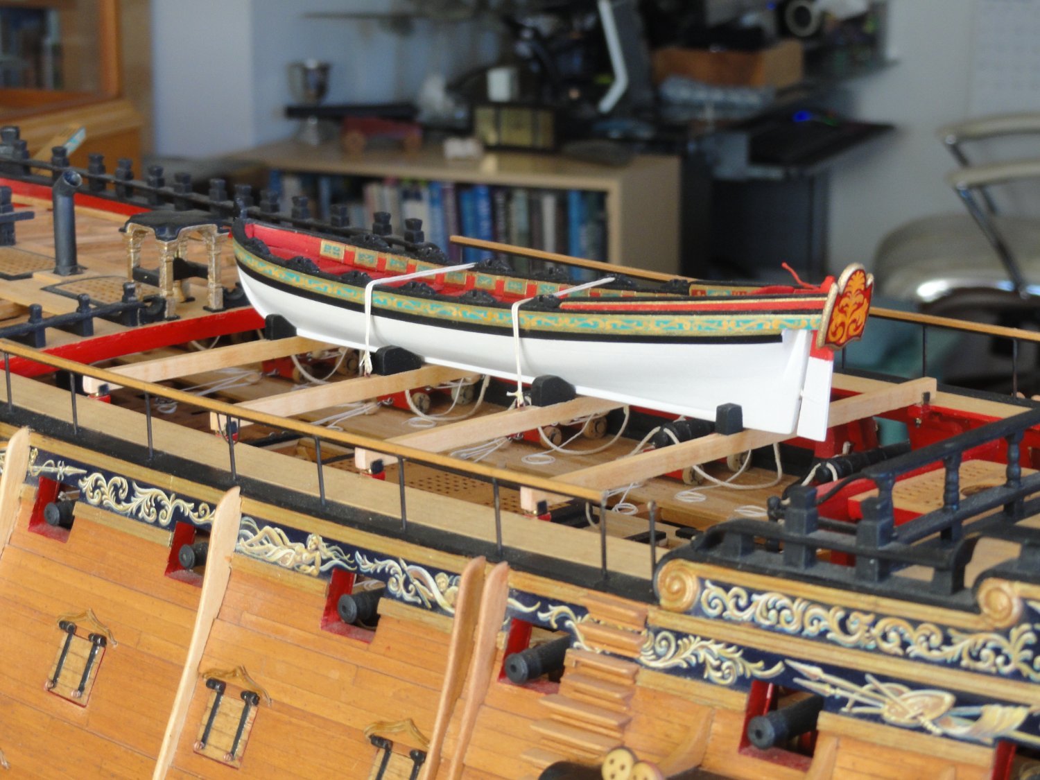
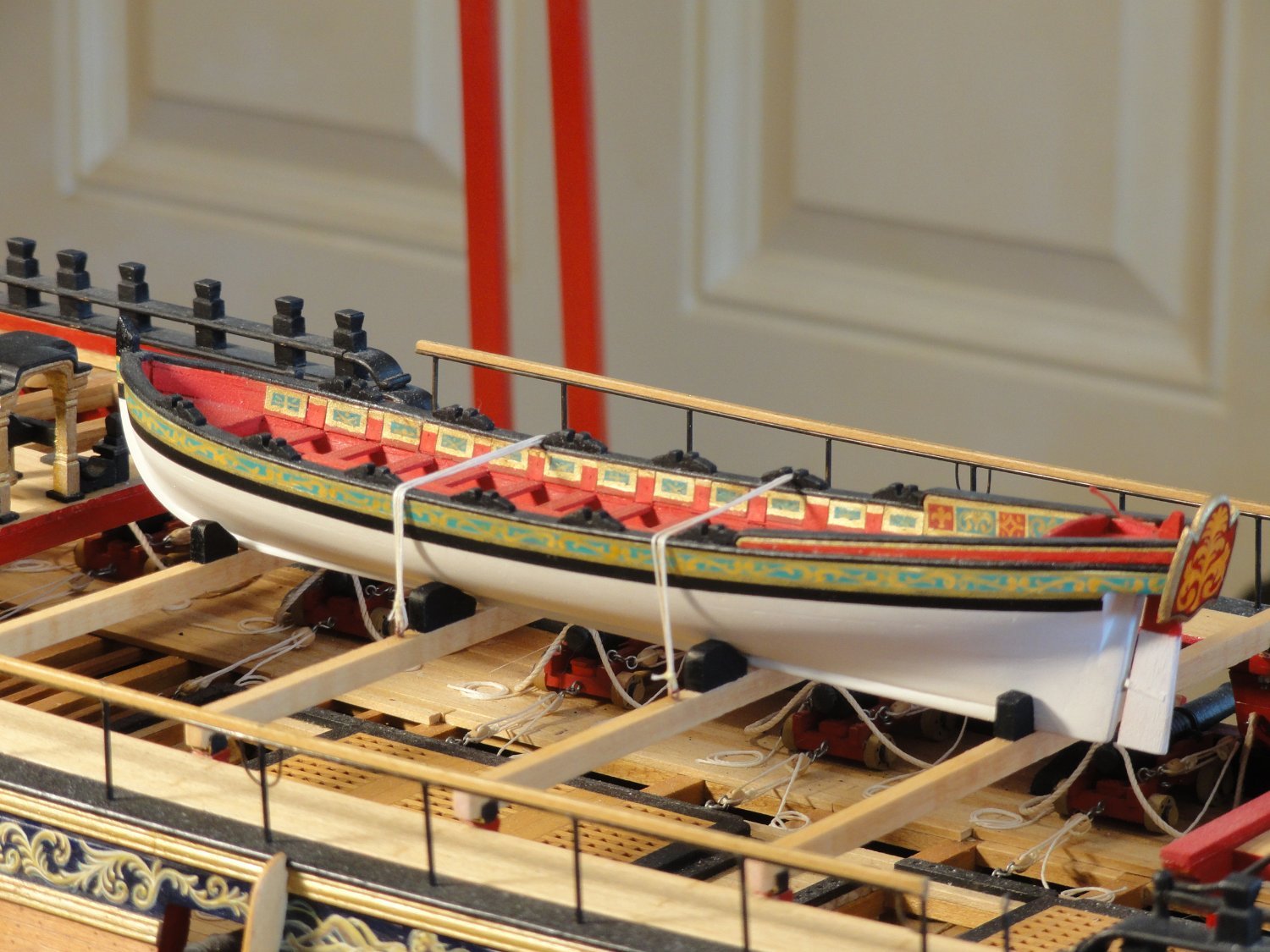
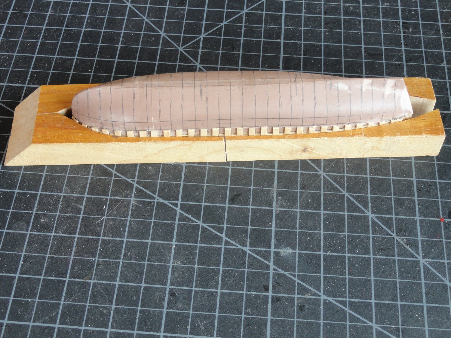
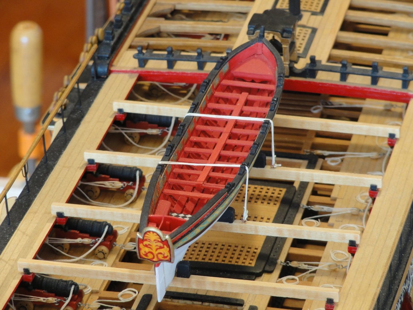
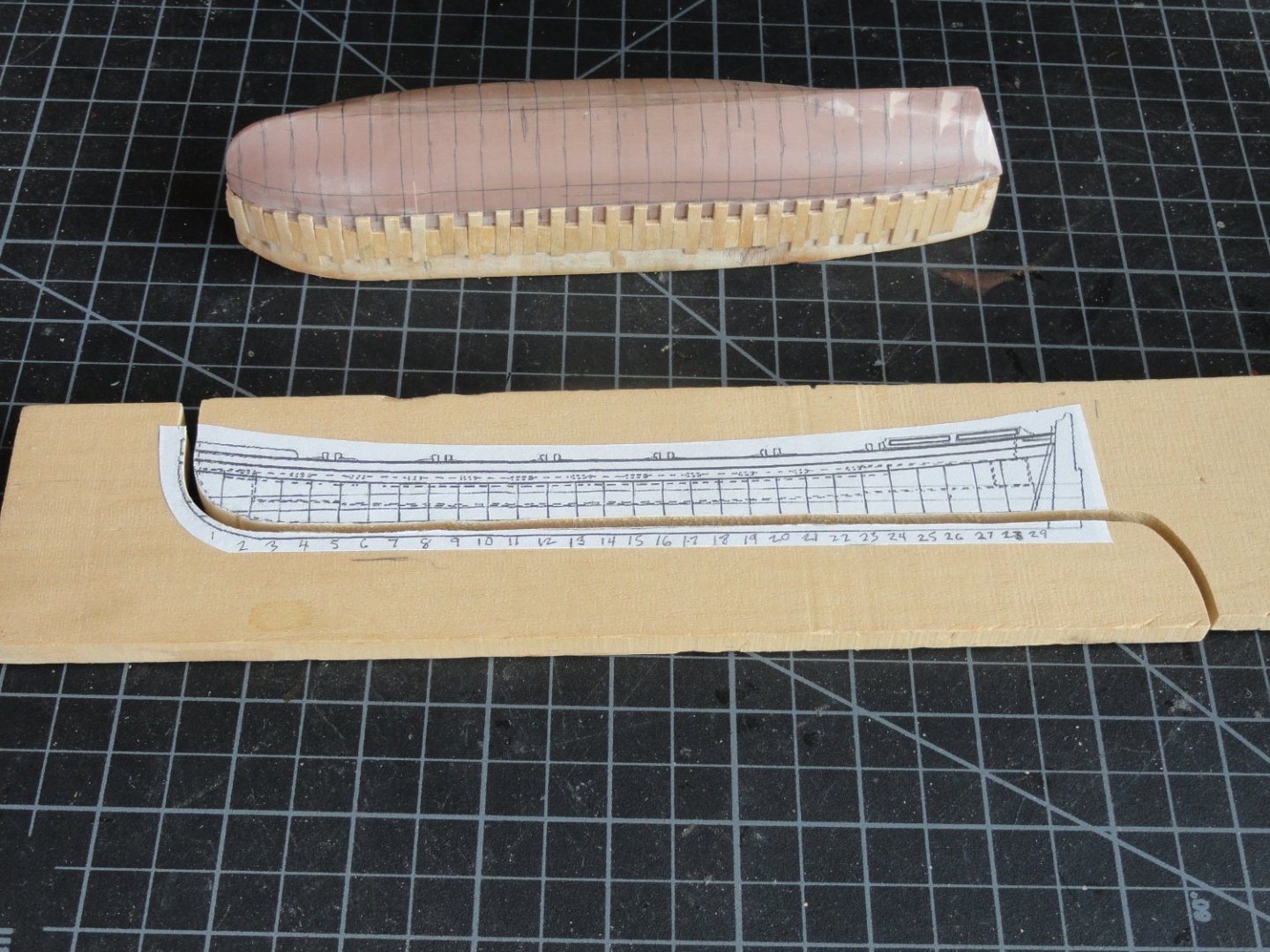
When all blocks were cut out they were aligned upside down on a flat surface covered with wax paper and glued together. Shaping was done with sanding blocks to match the frame lines. I traced the outline that would be the top of the boat on a scrap piece of maple, cut that with the band saw and glued the boat hull plug to that. I then discovered that by saving the cut off sections I could use those as clamps during the framing process. Next, the keel clamps. The whole hull construction is 1/8" wide thin strips of Basswood. The keel was laminated to the proper thickness, When dry both sides were carefully block sanded. On the upper side where the keel meets the hull wood 1/8" spacer blocks attached. The plug was sprayed with a couple of coats of clear lacquer then waxed so nothing would stick. Assembly was pretty straight forward. I centered the keel and taped it down fore and aft. Starting from the center thin strips, extra long were soaked in water for about 30 seconds. I did some pre-forming around a 1" wood dowel. I inserted the piece between the keel spacers with a small drop of glue and with smaller dowels rolled pressed to the hull and keel then attached the ends on both sides with a couple dabs of glue. Taped it in place with some blue tape, fit up the outer clamps, added another 1/8" spacer on each side of the frame. Repeated same until complete. Planking was done in the usual manner. Cutting hull loose along the sheer line established by the upper strake was pretty easy with a sharp No.11 Xacto blade. More sanding, primer, painting was next. I mixed a warm white with a touch of yellow and deck tan for the hull. Pure white is too bright for a scale model. As in a painting white should be reserved for that super white sparkle reflected by the Sun.


-
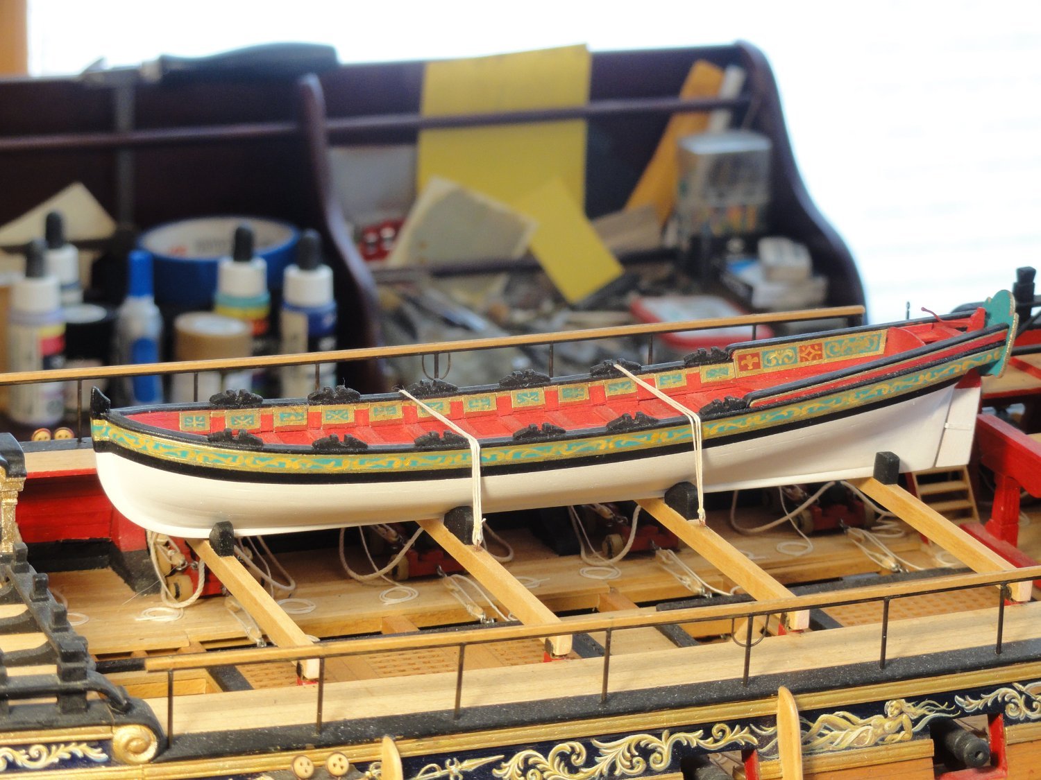
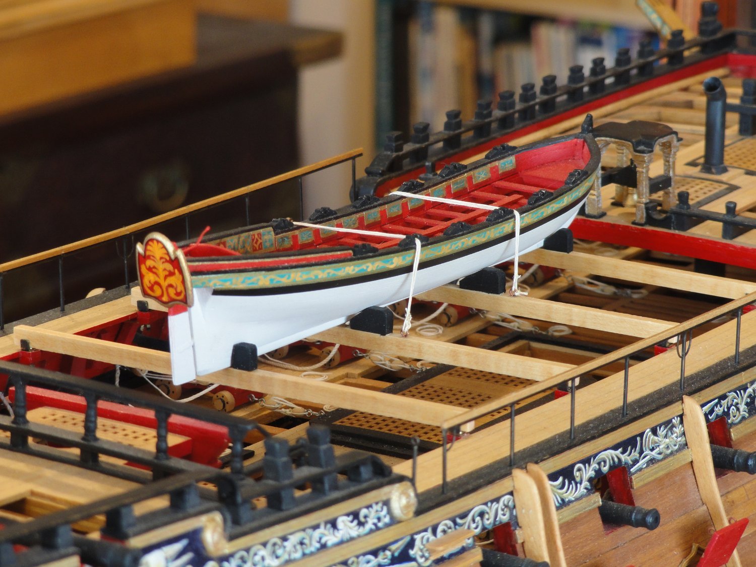
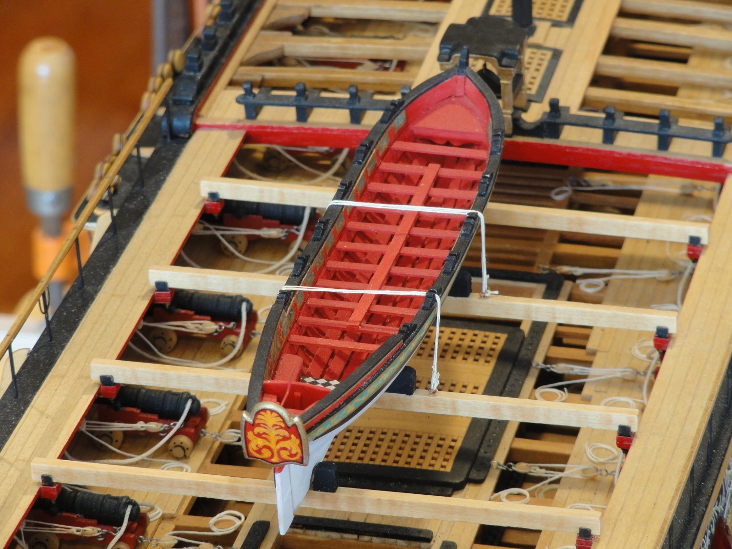
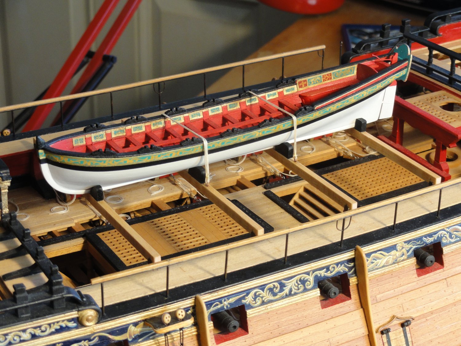
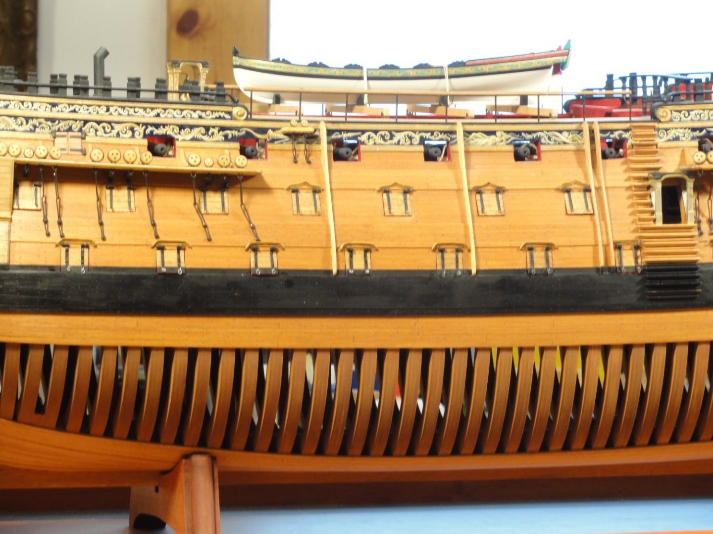
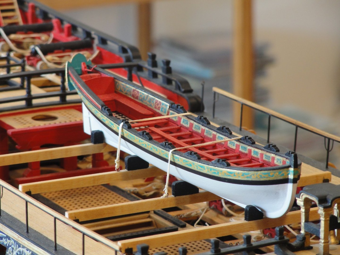
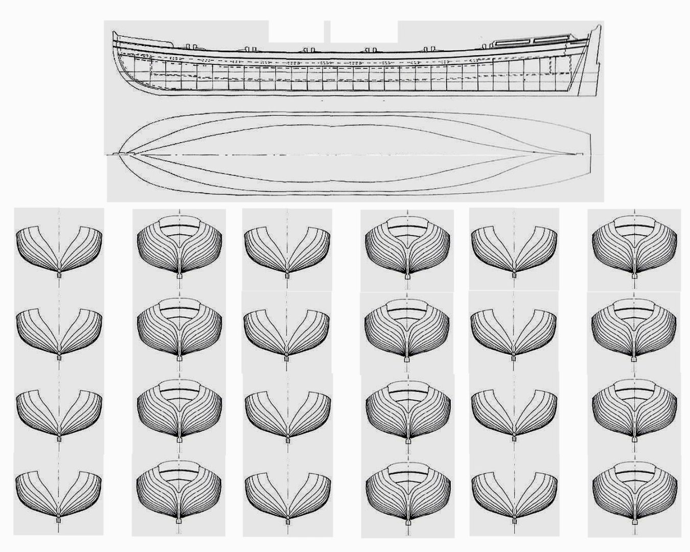
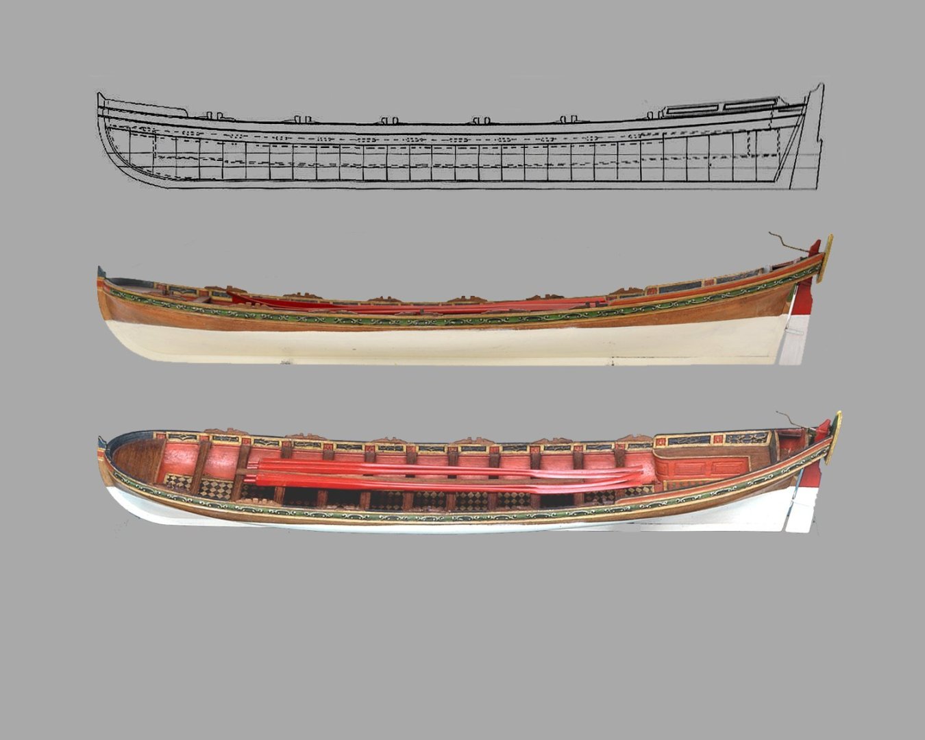
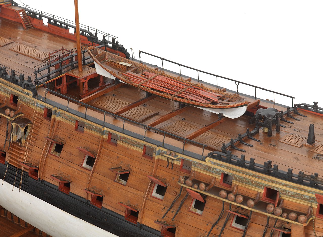
After completion of the quarter deck and poop deck it was time for a side excursion of a one off small project... the Admiral's barge. The design I chose was a carvel planked Pinnace single bank rowing platform. The oarsmen were staggered fore and aft with longer sweeps for speed. The crew was twelve at the oars plus the coxswain at the tiller. These boats were long and narrow. The barge on 1765 model of Victory scales out close to 40 feet. Using Photoshop I elongated the the profile by adding two extra rowing stations amidships then made multiple copies of the frame stations to paste on the Renshape blocks for cutting on the jigsaw.

-
Thanks, Albert. Thank you, Kevin. Tamiya Red X-7 acrylic paint. Thanks, Druxey. To paraphrase Longridge, "I can sleep at night, rest assured, that the job has been done properly." Thanks, Jason.
-
Thanks for your interests and "Likes" everyone. Some more shots from 5-22.

-
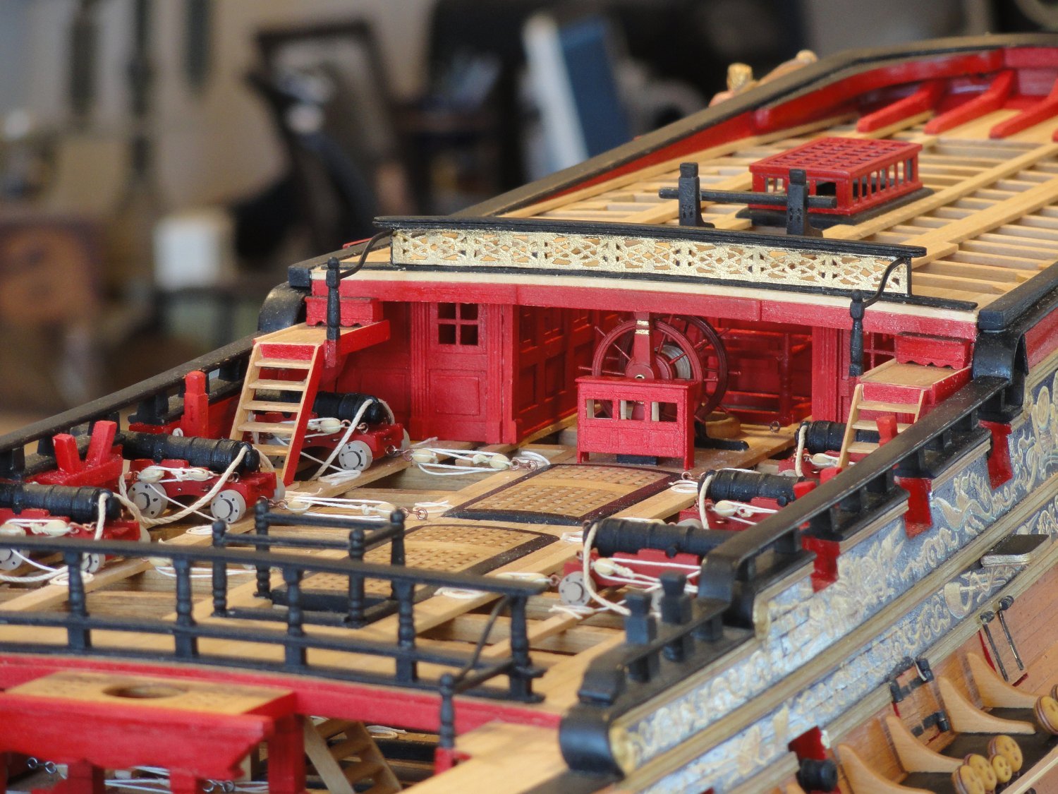
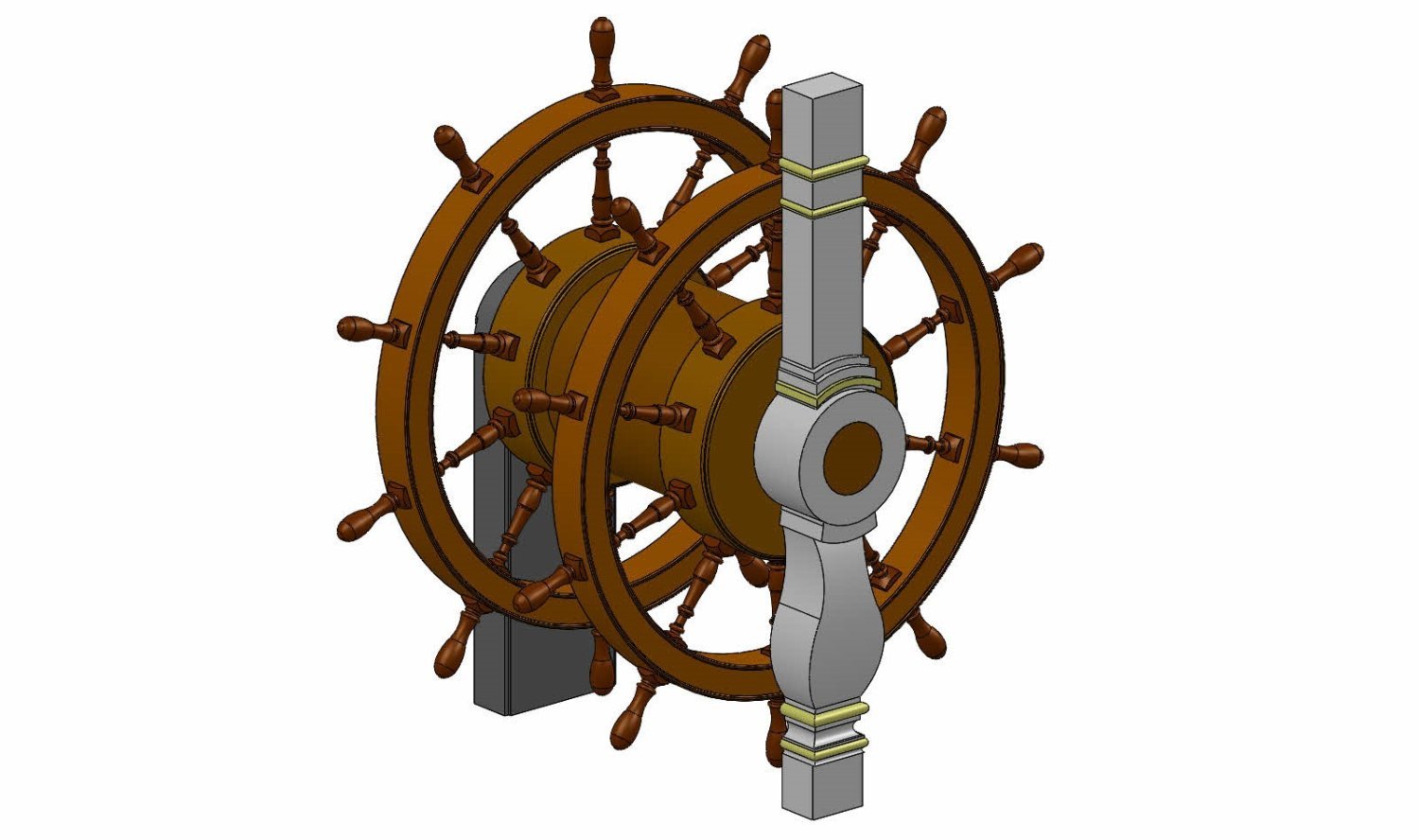
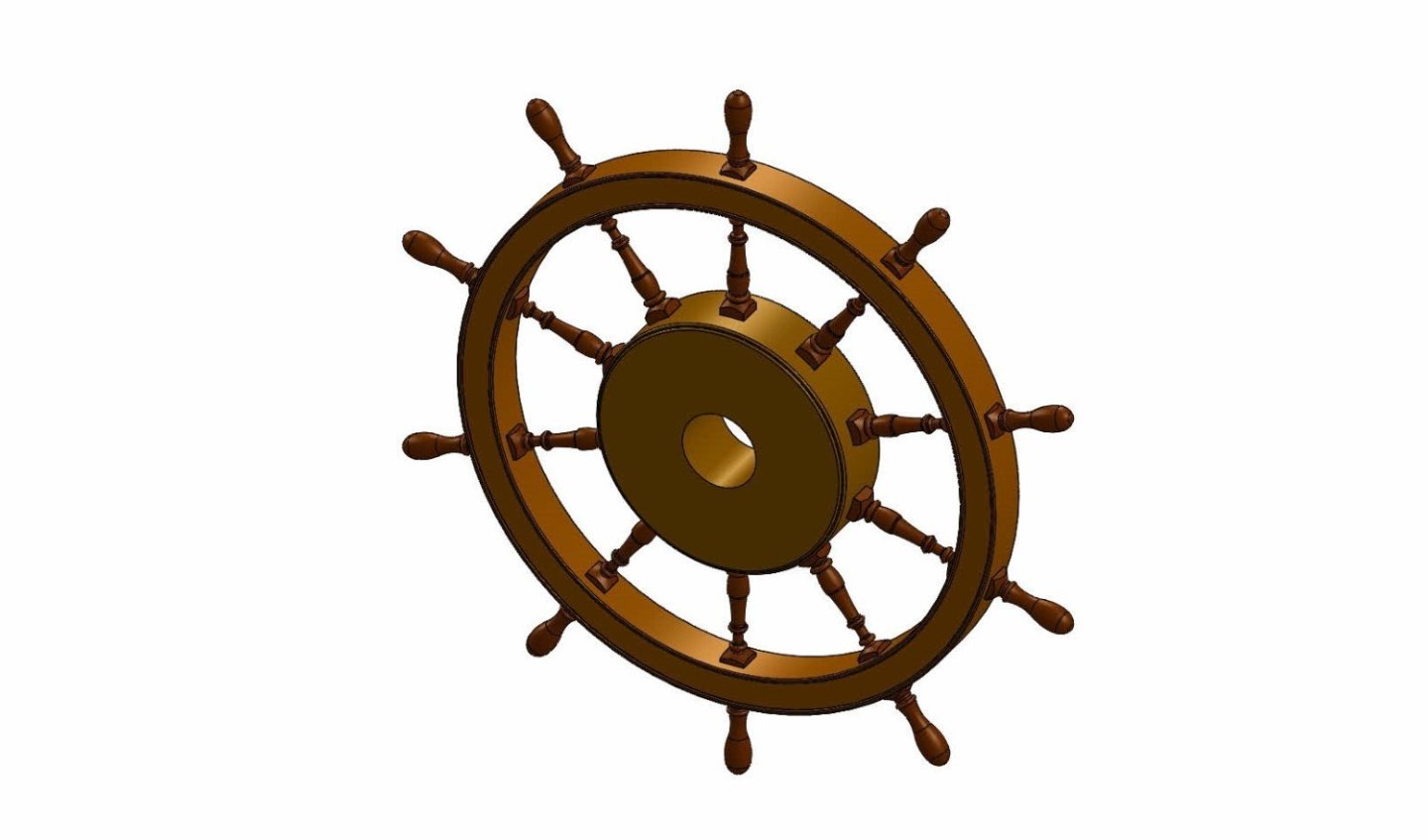
The ship's wheel. About 20 years ago, after the lower deck was completed, it was time to fabricate the rudder. The steering gear assembly, consisting of the tiller, tiller sweep, and tackle, resides just below the middle deck framing. It was built to be fully operational. Over the years, deck by deck, I made sure the tiller ropes were passed up through the structure. With so many mini-projects which are the sum of the whole involving ship building, the wheel was on the back burner of my mind. How and the heck was I going to build it? As an artist, if I don't have a solution, I bypass it and work on other parts of the task at hand. The elephant in the room will tell me when it's ready. Finally I was approaching the point where I had to come up with the solution. My long time friend, Simon, suggested 3-D printing. I gave him the scaled drawings (McKay) and photos of Victory's helm. In "Solid Works" he reproduced the wheel with all the numbers crunched for printing. This was sent off and when it came I knew it would not withstand the sands of time. Too fragile. It broke just trying handle an installation. The spokes were the problem. The time and energy to try a method which failed was not wasted. It was the catalyst that lit the light bulb of a successful solution. In my studio is a large cabinet full of 1:32 models of WWI airplanes. I use Albion Alloys Ltd. Nickle tubing for turnbuckles for tensioning the rigging. 0.7mm o.d. x 0.5mm i.d tubing telescoped over .05mm tubing would look perfect. I turned the wheels, hubs, and barrel on my lathe. I built a fixture, that I can't seem to find, to center everything. The tubing is cut to proper lengths by rolling sharp #11 Xacto blade over it. I twist the tip of the blade inside the tubing to remove burrs and file the outside edges to round them off. After a couple layers of paint they appear to be lathe turned. The whole assembly is very strong. After installation I gathered the tiller ropes, clamped the rudder to one side, did seven wraps around the barrel, and spliced the ropes. Once the rudder was centered, the splice disappeared below decks. I had a working ship's wheel that turned the rudder. After showing my wife and a few friends how it worked, I came down from cloud nine and decided to stop doing that. I came to the realization that I don't have a miniature boatswain to fix it if something wears out.

-
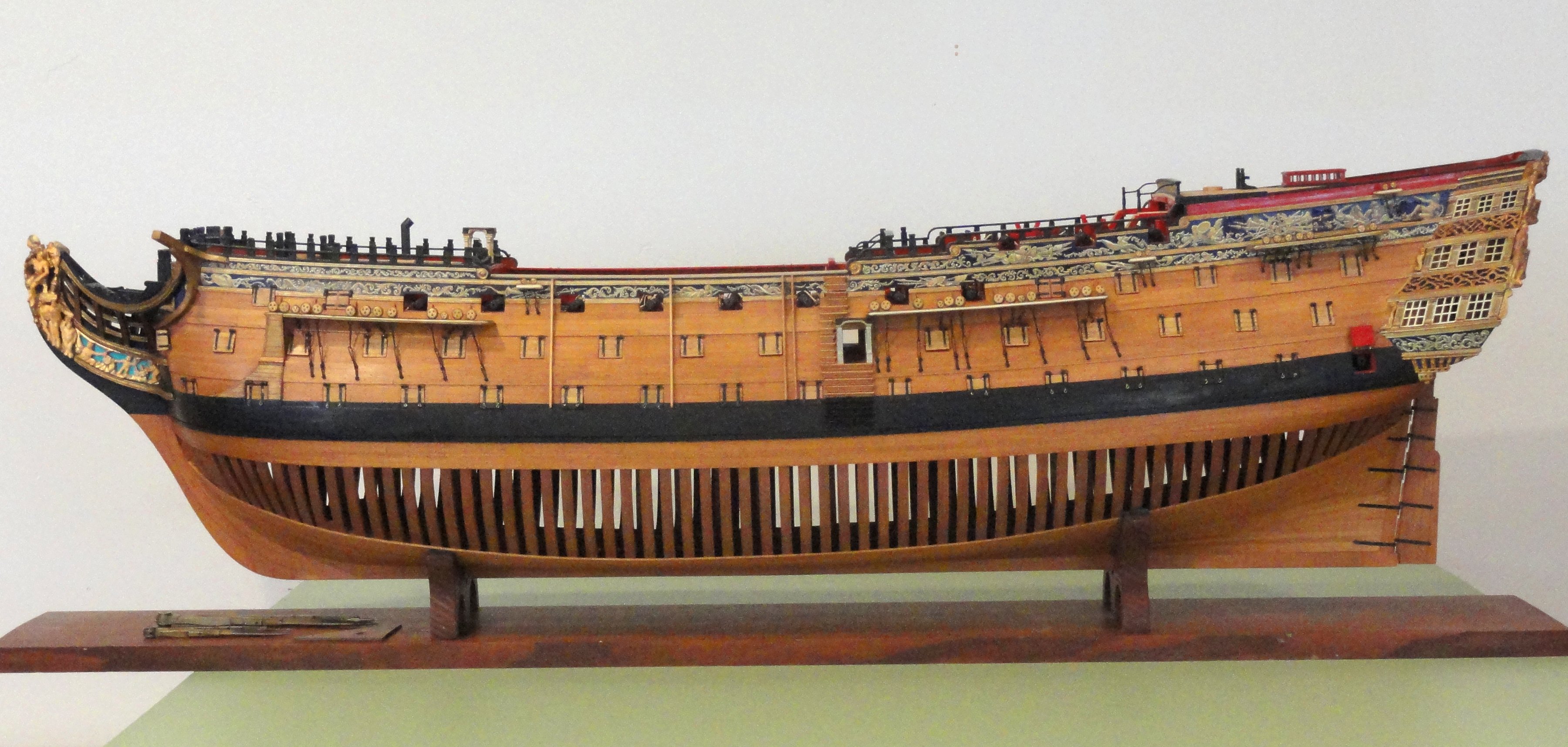
Hi Lieste, I am fully aware of what you say. Earlier in my build log I explained that I am building a modern hybrid version Victory, Not an exact copy of the 1765 version. More accurately she should be bread and butter construction, as in the contemporary models of the time, not plank on frame. Further she will not be displayed on the ways when finished. That was just the building board. So you're not a party pooper after all. Steve
-
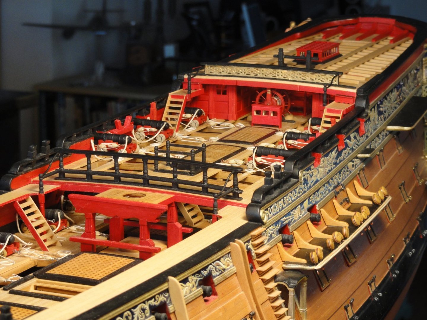
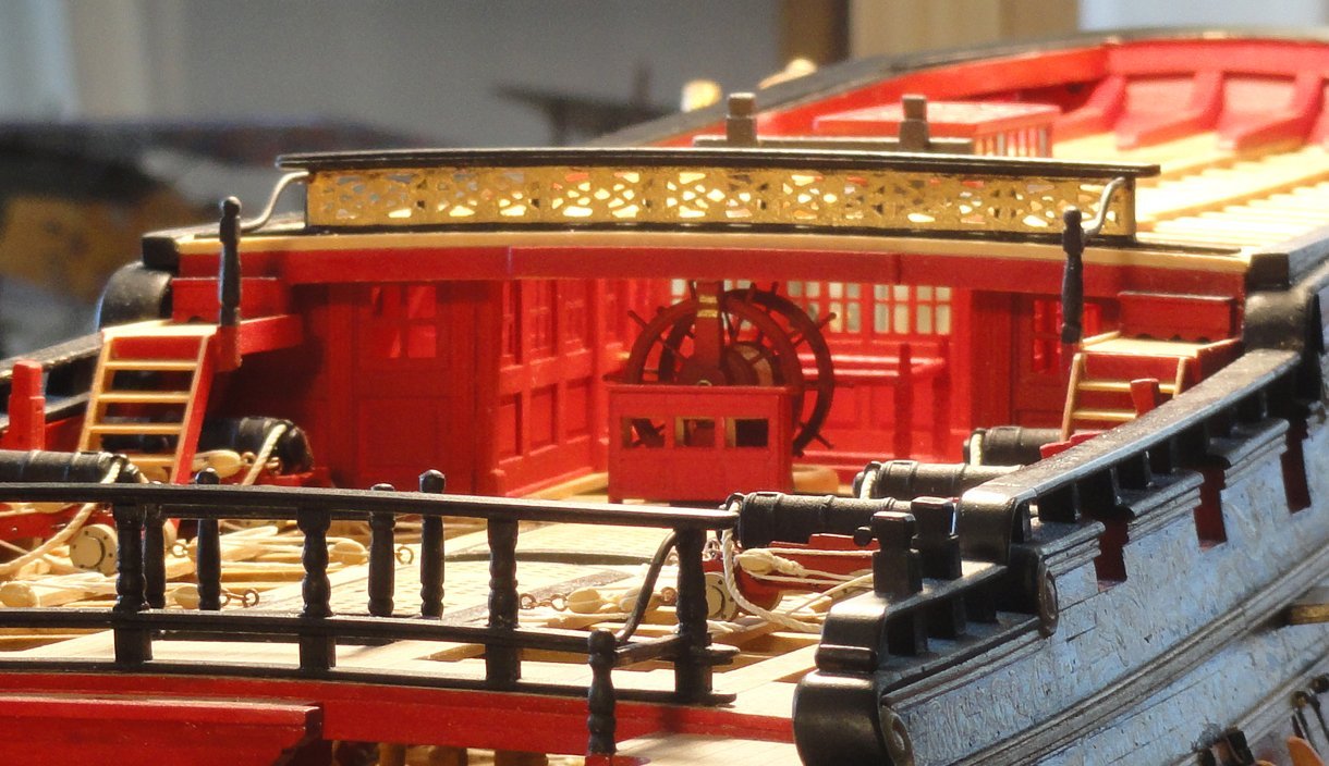
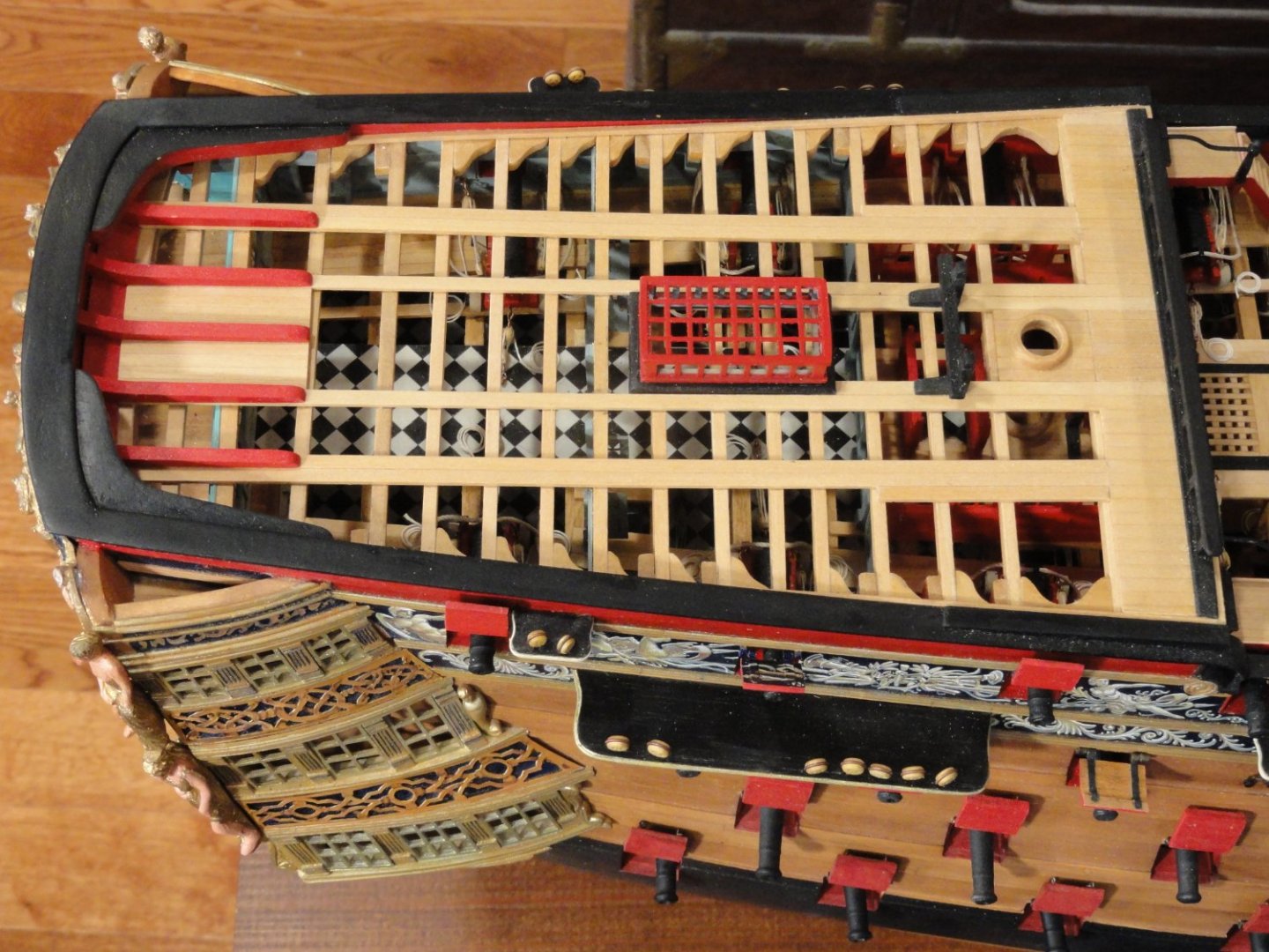
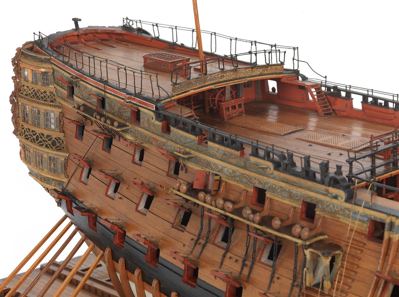
We might as well get a view of the Captain's quarters through the framing of the poop deck. The Master's cabin can be seen on the larboard side just under the poop deck break and the Secretary's cabin on the starboard side. Aft with the checkered flooring is the Captains' dining and day cabins opening on to the balcony. What a magnificent view it must have been.
-
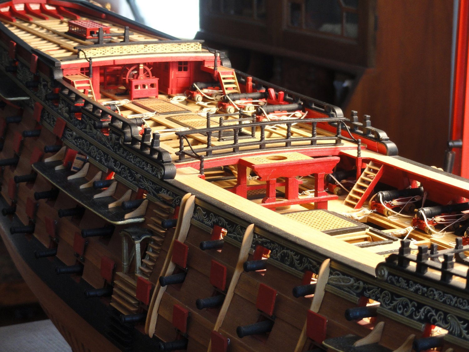
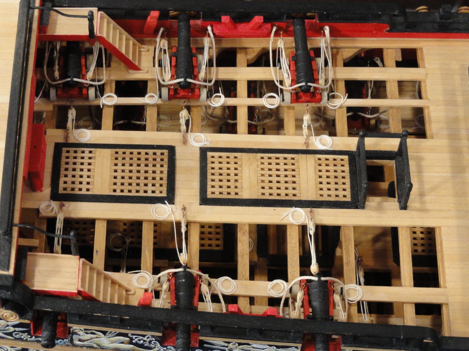
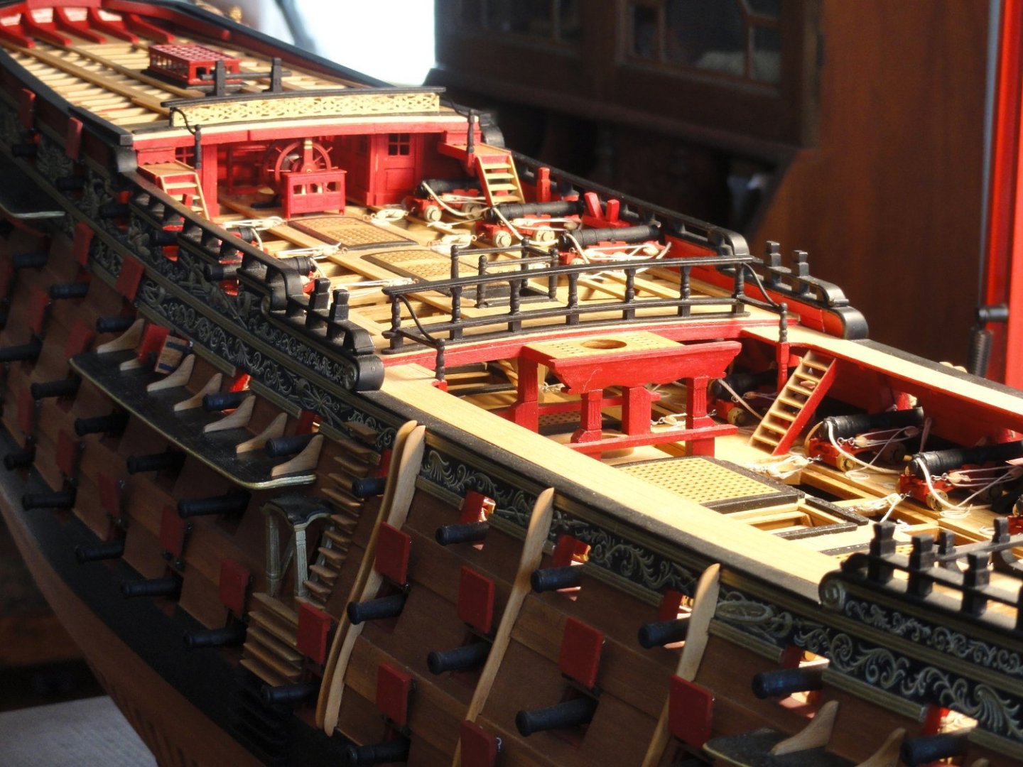
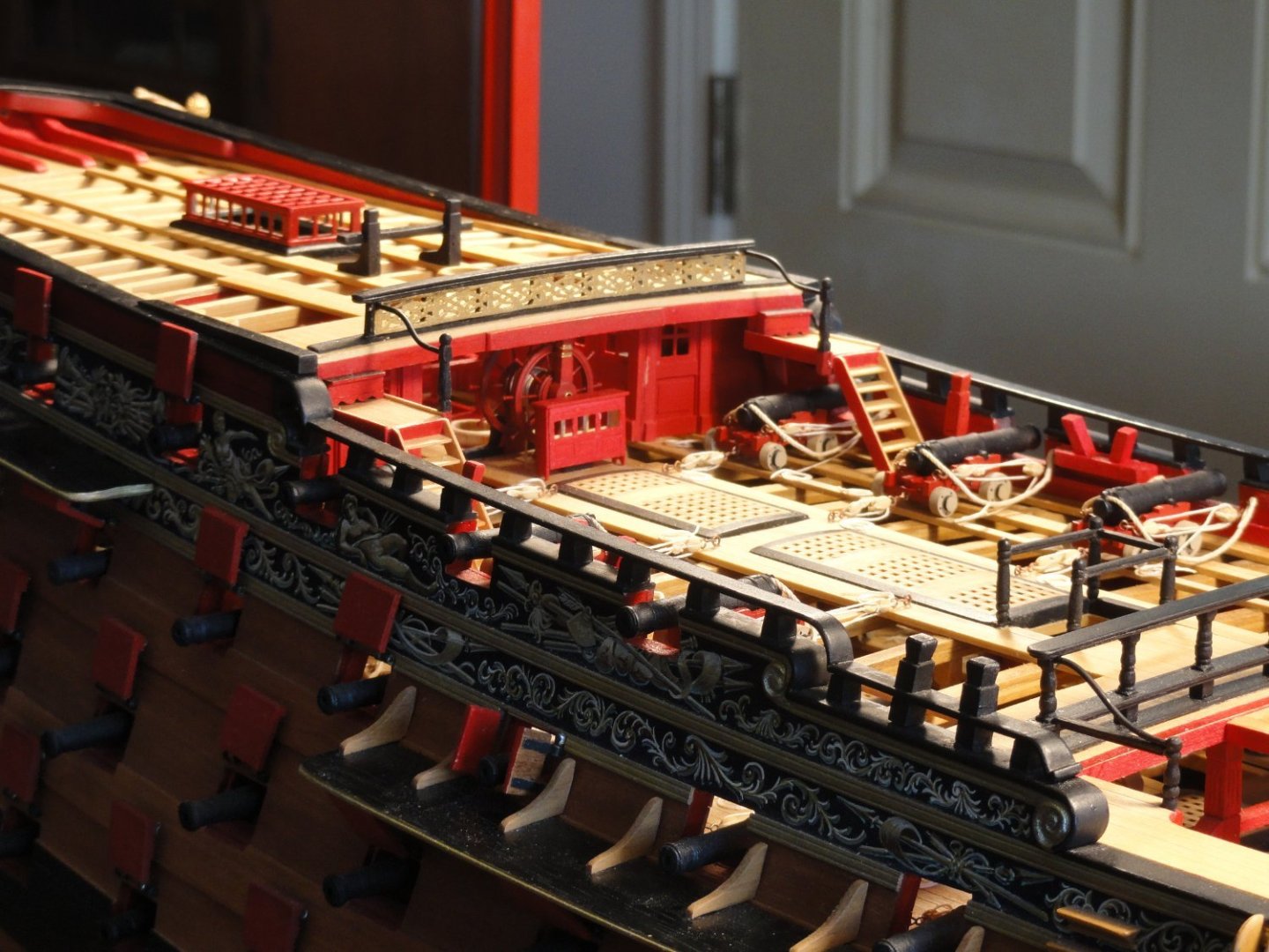
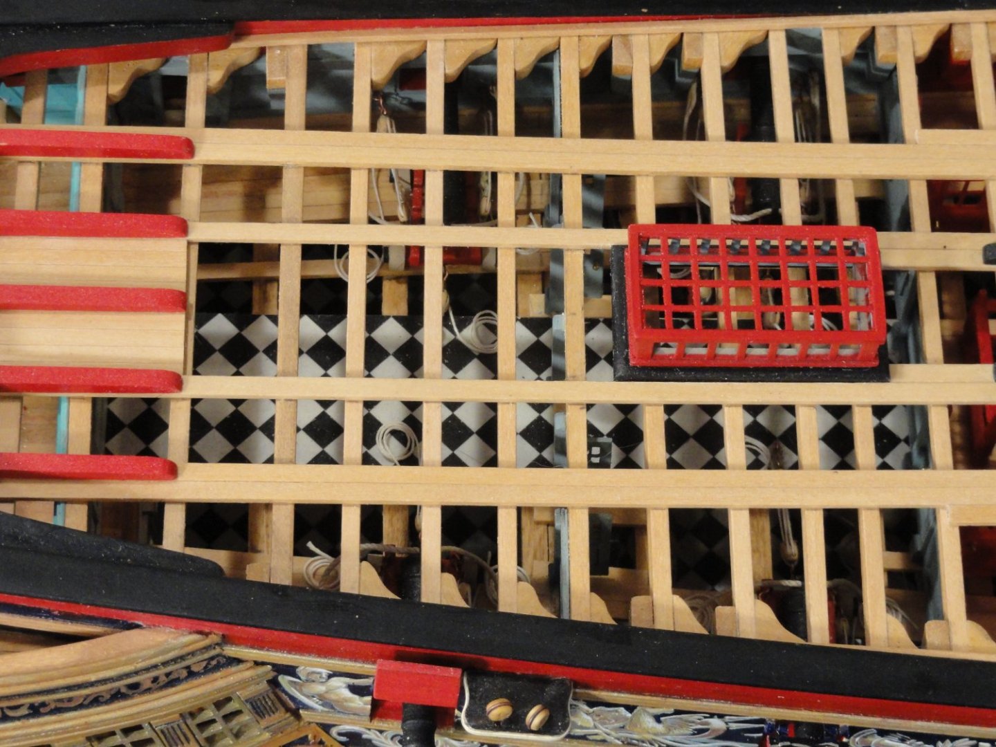
Part 10 The Quarterdeck. This phase of the ship construction was really fun and rewarding. What I'd visualized years before was becoming a reality. Utilizing photos of the 1765 models, while making notations on G. F. Campbell's drawings (Longridge), enlarged to 1:64 scale, I was able to reconstruct the late 18th Century elegant version of Victory. Building the gangways connecting the forecastle to the quarterdeck was the first order of the day. A nice little project with ladders and turned pillars in red that support the descending rail and aft part of the gangway. The quarterdeck balustrade is framed up so all the pieces interlock, then glued, for greater strength. Basswood is used for all such structures. Stanchions are lathe turned. Planking and grates were next. I kept planking more open here for better visibility to the upper deck details. Believe me there's a lot of stuff on the decks below that no one will ever see unless they have a fiberoptic scope to poke through a gunport. Stag horns, kevels, and shot lockers were next. Finally 6 short twelves were laid in. More to come and thanks for your interest and comments.


-
Thanks, Gary. My pleasure. Thanks Mark. Much appreciated.