John Murray
-
Posts
58 -
Joined
-
Last visited
Recent Profile Visitors
303 profile views


-
 John Murray reacted to a post in a topic:
HMS Thorn by Kevin Kenny - Swan class 1:48 scale - David Antscherl practium
John Murray reacted to a post in a topic:
HMS Thorn by Kevin Kenny - Swan class 1:48 scale - David Antscherl practium
-
John Murray reacted to a post in a topic:
HMS Thorn by Kevin Kenny - Swan class 1:48 scale - David Antscherl practium
-
John Murray reacted to a post in a topic:
HMS Thorn by Kevin Kenny - Swan class 1:48 scale - David Antscherl practium
-
mtaylor reacted to a post in a topic:
HM Sloop Echo 1781 Cross Section by John Murray - 1:48
-
mtaylor reacted to a post in a topic:
HM Sloop Echo 1781 Cross Section by John Murray - 1:48
-
mtaylor reacted to a post in a topic:
HM Sloop Echo 1781 Cross Section by John Murray - 1:48
-
KARAVOKIRIS reacted to a post in a topic:
HM Sloop Echo 1781 Cross Section by John Murray - 1:48
-
CiscoH reacted to a post in a topic:
HM Sloop Echo 1781 Cross Section by John Murray - 1:48
-
GrandpaPhil reacted to a post in a topic:
HM Sloop Echo 1781 Cross Section by John Murray - 1:48
-
davec reacted to a post in a topic:
HM Sloop Echo 1781 Cross Section by John Murray - 1:48
-
davec reacted to a post in a topic:
HM Sloop Echo 1781 Cross Section by John Murray - 1:48
-
Cheers. What I meant though was I am not sure if that is the same as what you would know as English lime. I am not sure of the source of the timber.
-
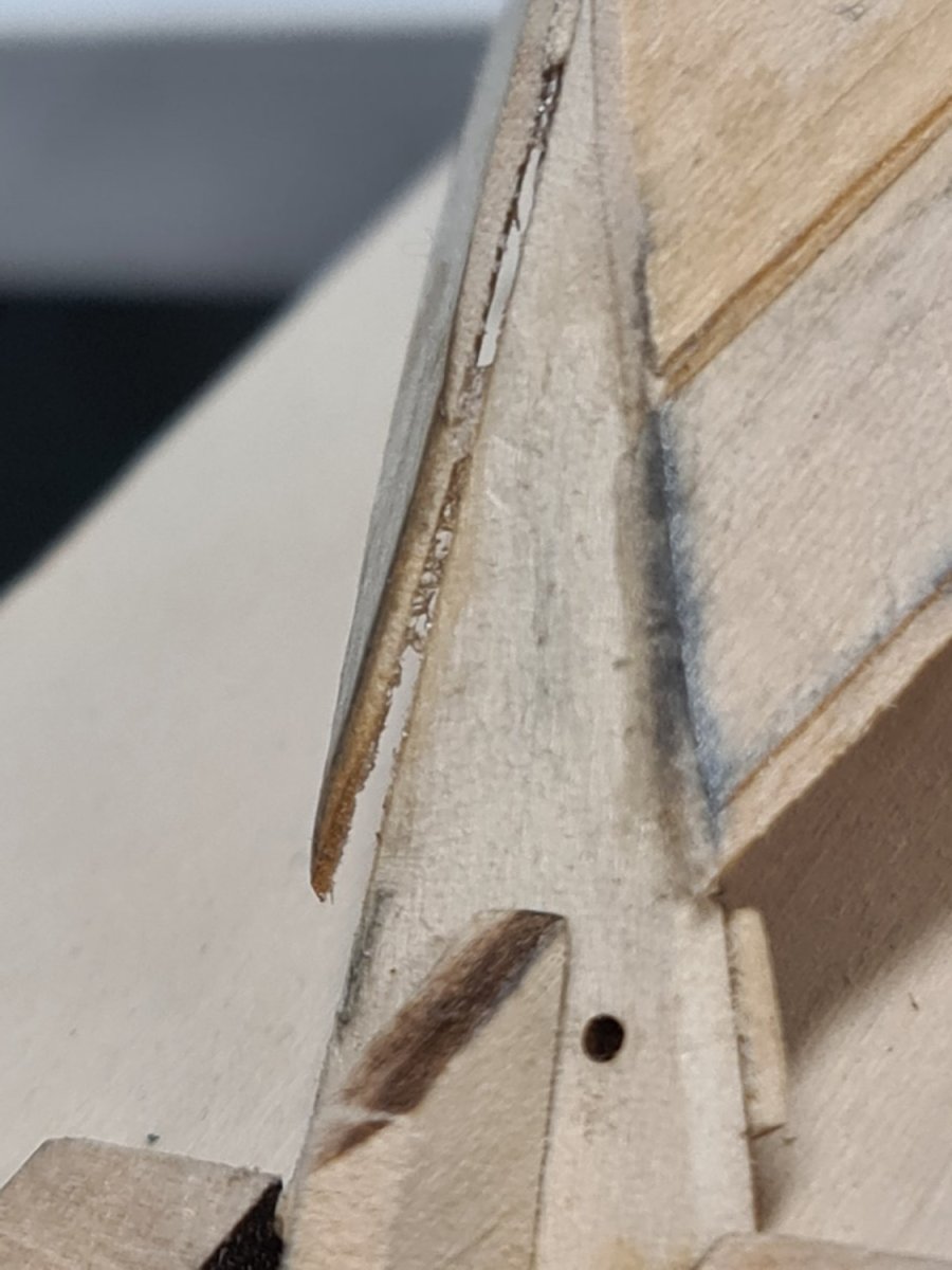
Cheers for that. It is English lime. That is what it is called in Australia. What its botanical name is though? Thank you on the workmanship. Re that image, I tried to avoid the cross grain as much as I could. That example has the timber extending out of site, however, I shall keep a closer eye on that. I shall be restraining the top-timbers movement from now on to prevent this issue recurring.
-
 John Murray reacted to a post in a topic:
HM Sloop Echo 1781 Cross Section by John Murray - 1:48
John Murray reacted to a post in a topic:
HM Sloop Echo 1781 Cross Section by John Murray - 1:48
-
JpR62 reacted to a post in a topic:
HM Sloop Echo 1781 Cross Section by John Murray - 1:48
-
ccoyle reacted to a post in a topic:
HM Sloop Echo 1781 Cross Section by John Murray - 1:48
-
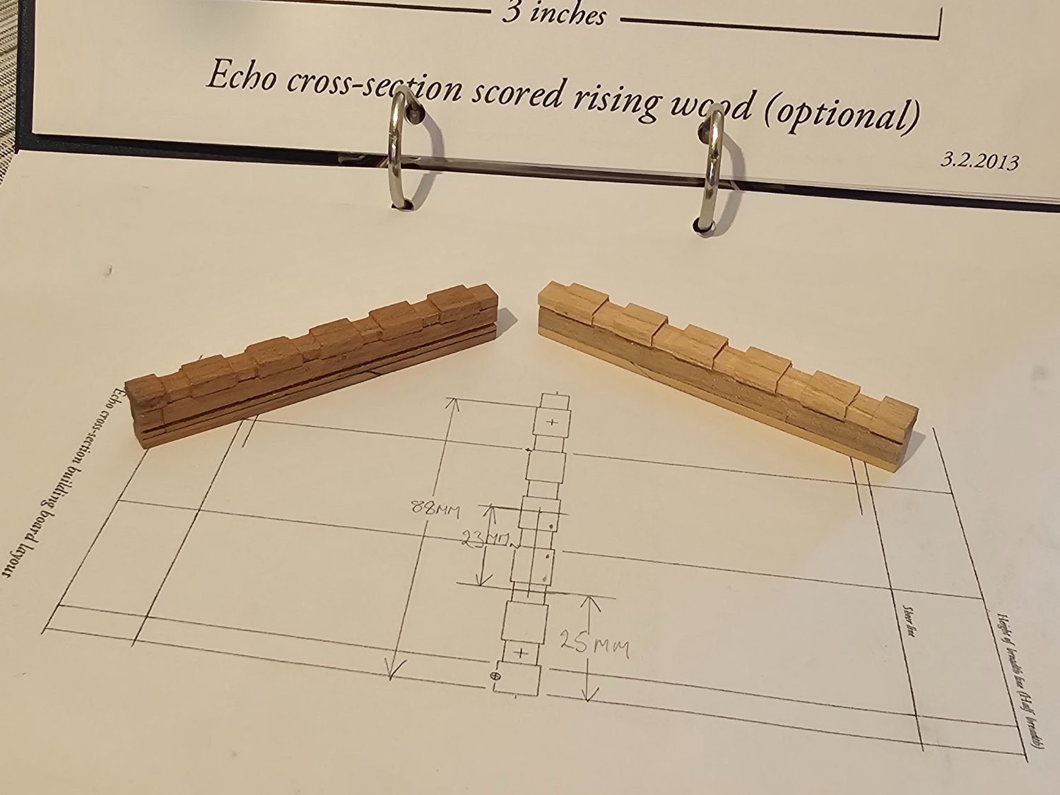
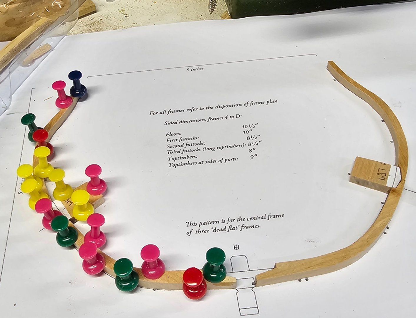
Hi Greg, Yup, it was a shock to me. I bought the English lime in Adelaide South Australia from a specialist wood supplier for furniture and specialised woodworking needs. I believe it has been dried. I would be very surprised if not. The English lime block was ripped into sizes I can handle several months ago by a community woodworking outfit. From there I band-sawed into 10mm thick planks. The temperature on garage varies through the day from very warm to quite cool to cold in winter +40c to 0c. I have had the timber around 3 months. It was sawn around 8 weeks ago. I wasn't sure if the Titebond II glue I used has "crept" in the garage after curing. I think I shall print more paper of each frame, glue each to a piece of Masonite, then pin each frame over the relevant print so as to hold each frame securely until it is time to assemble. I think I will need to fit the cross section out. Are plans or parts available to plank, deck, etc this model? Just in case it starts creeping out over time. I will be remaking the dead flat #1 and shall be considering this issue. Thanks for your thoughts. I very much appreciate it. These are only sitting in place. Not fixed but just to illustrate the issue. The middle on was done around 6 weeks ago. The other two within the last two days.
-
Afternoon all. After a layoff of around 6 weeks due to xmas, these last few days had me remaking the dead flat on my HM Sloop Echo cross section. I made the dead flat #1 6 weeks ago. I have distortion of the 6 weeks old frame. I did not seal it it occurs to me. Should I do that when it is made and assembled? I describe the issue further here. Thank you.
-
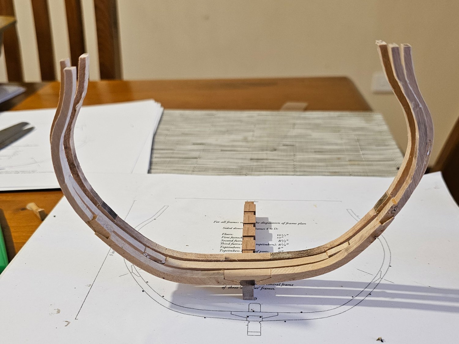
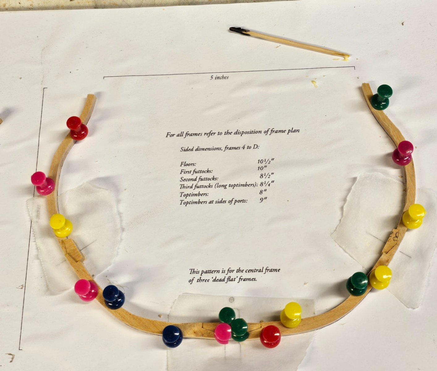
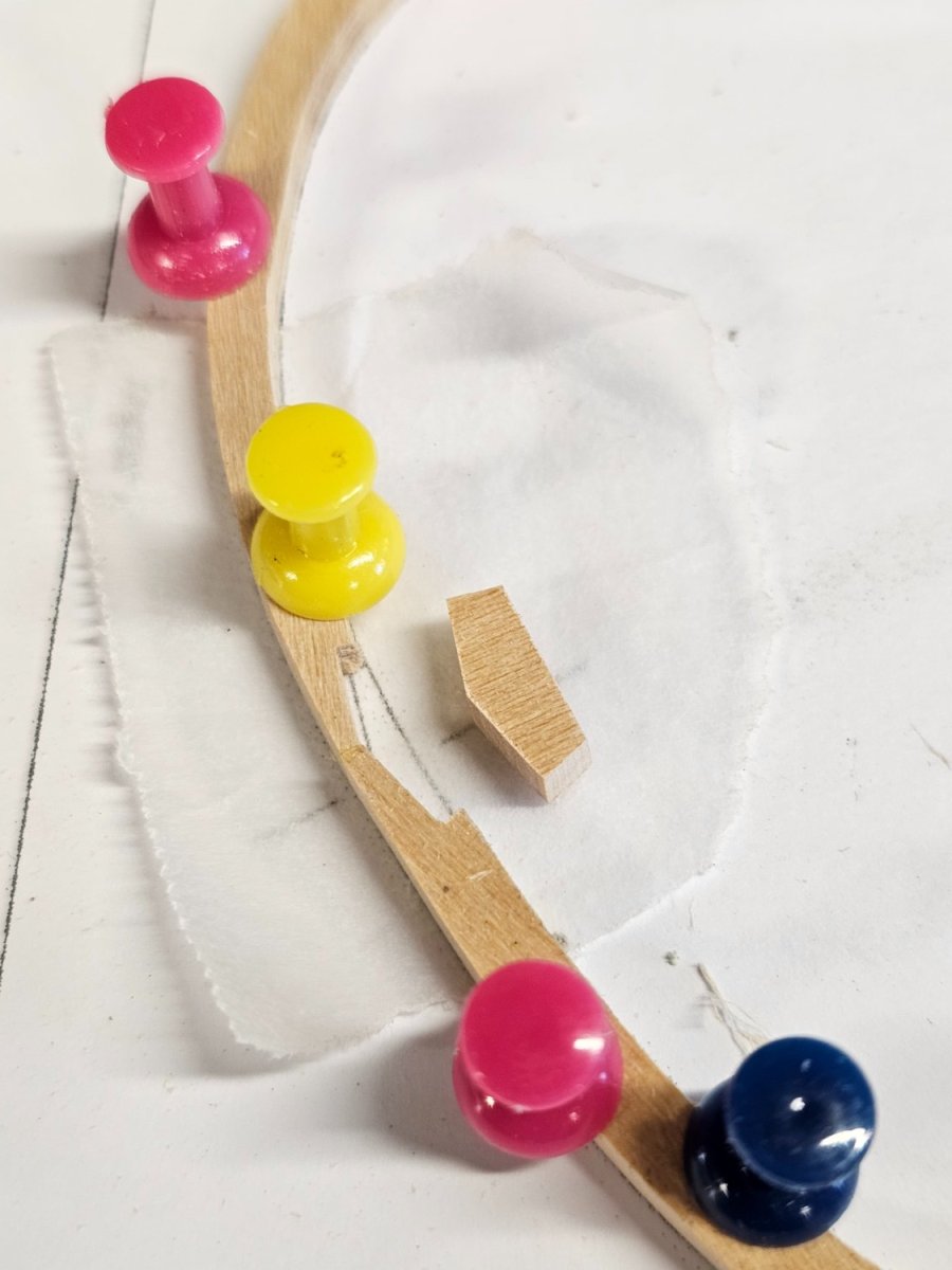
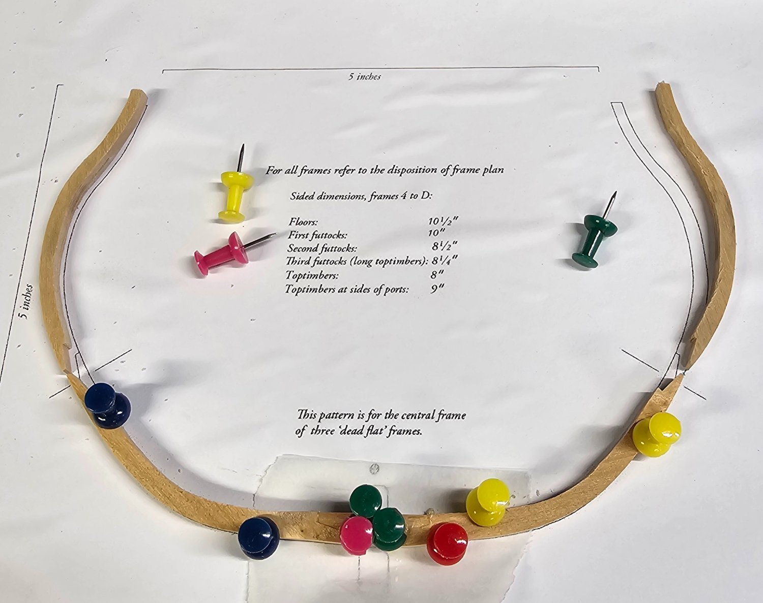
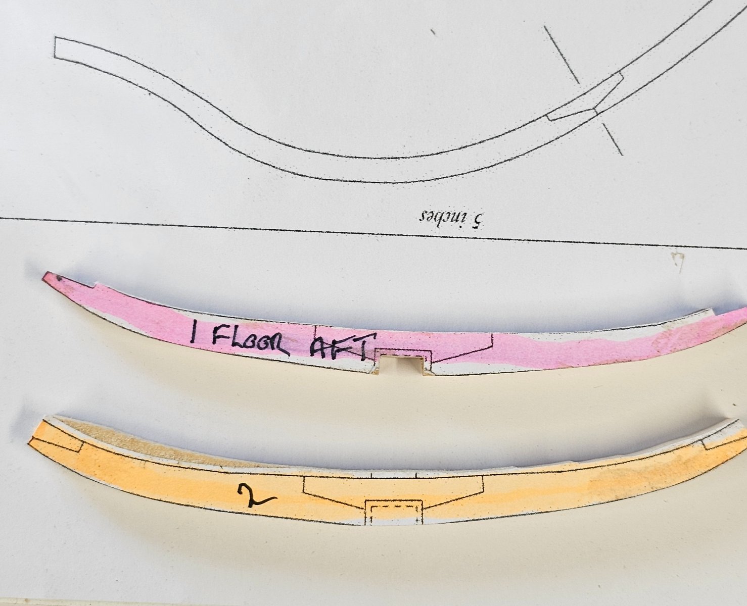
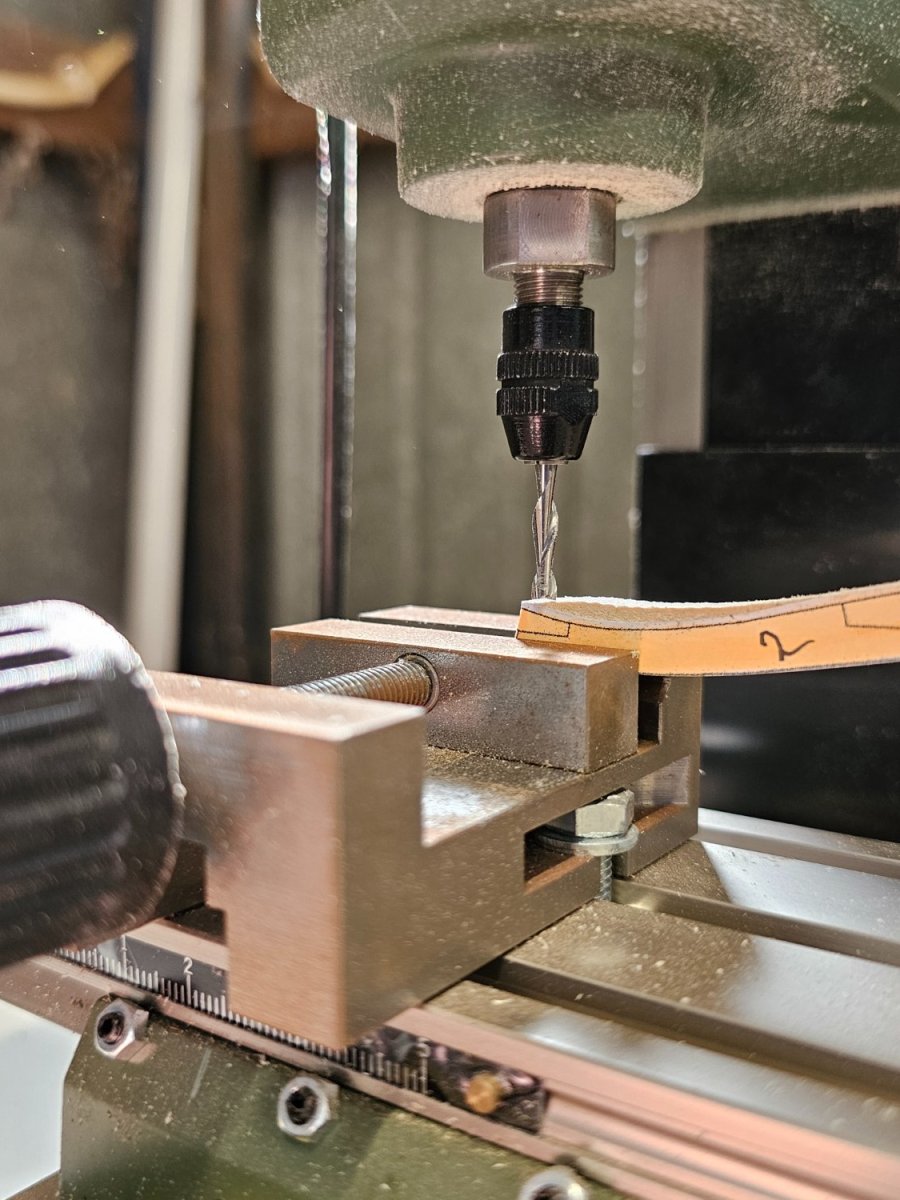
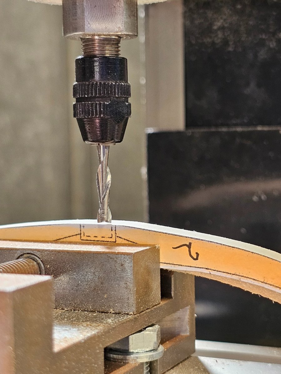
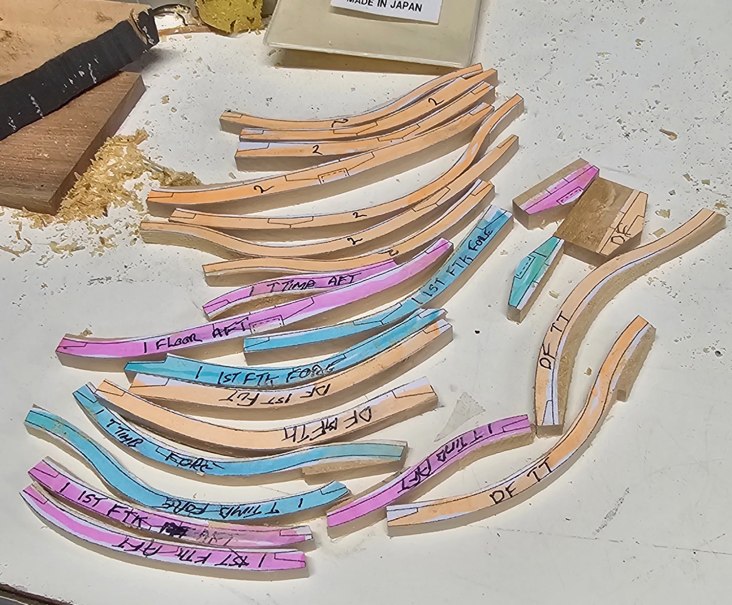
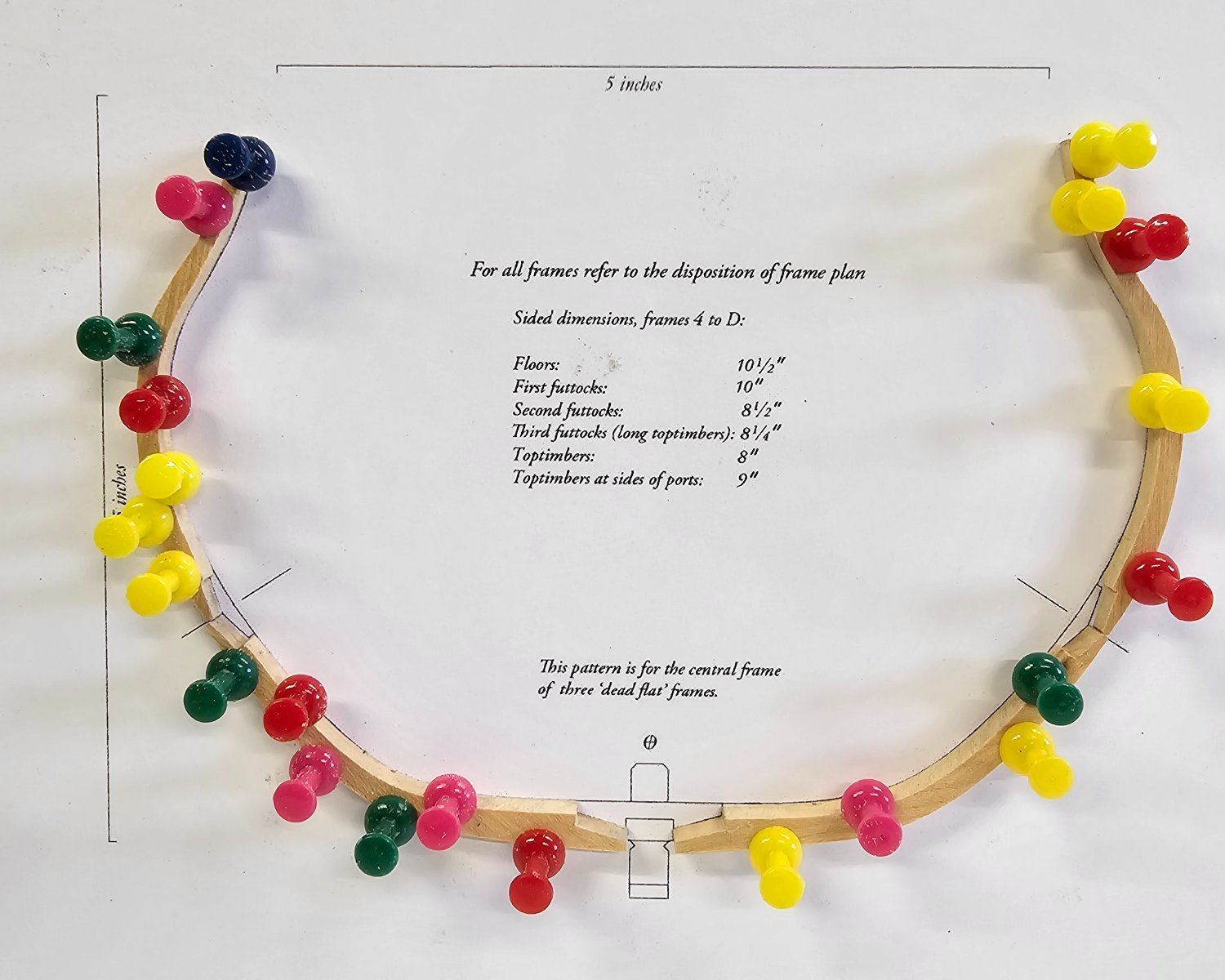
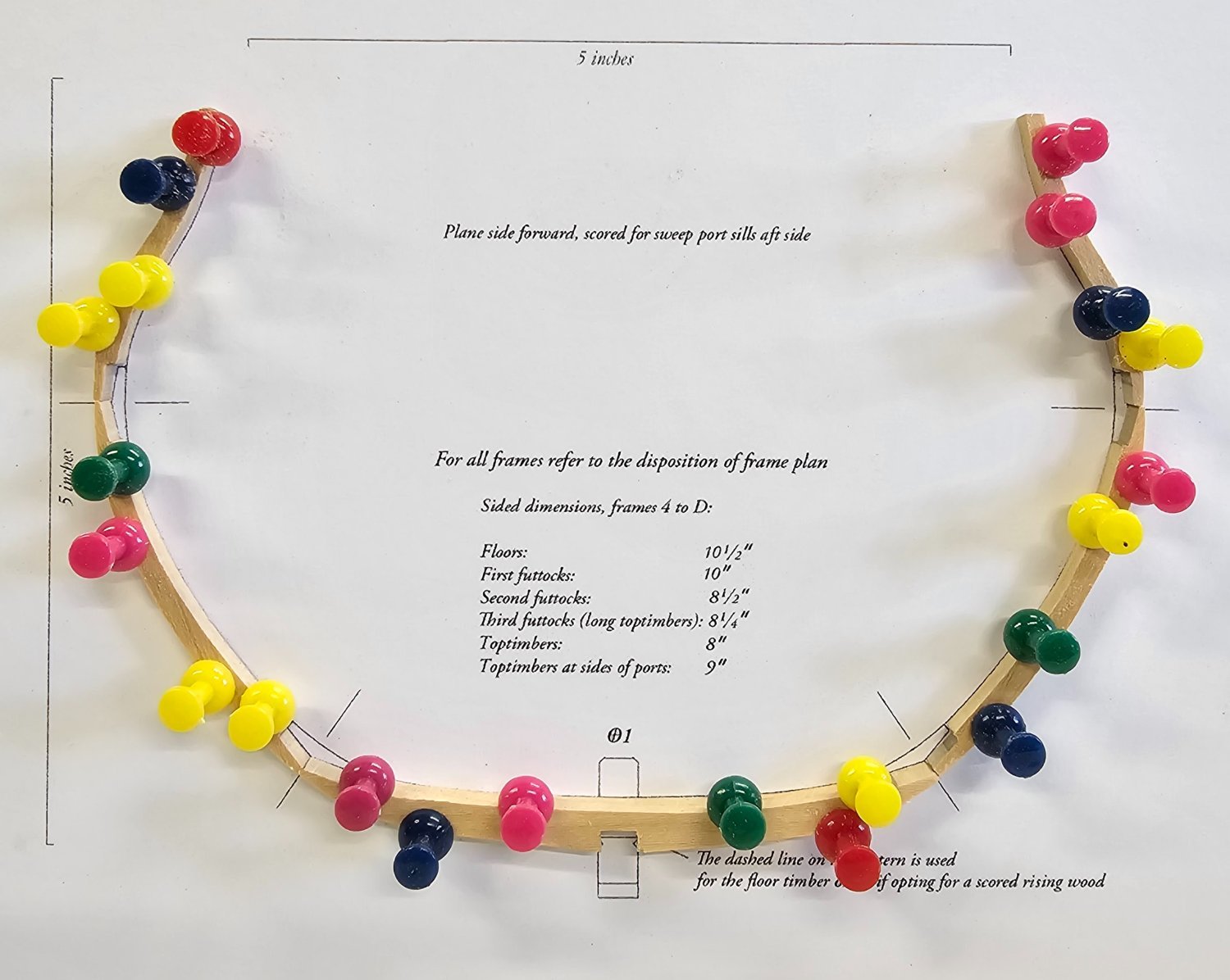
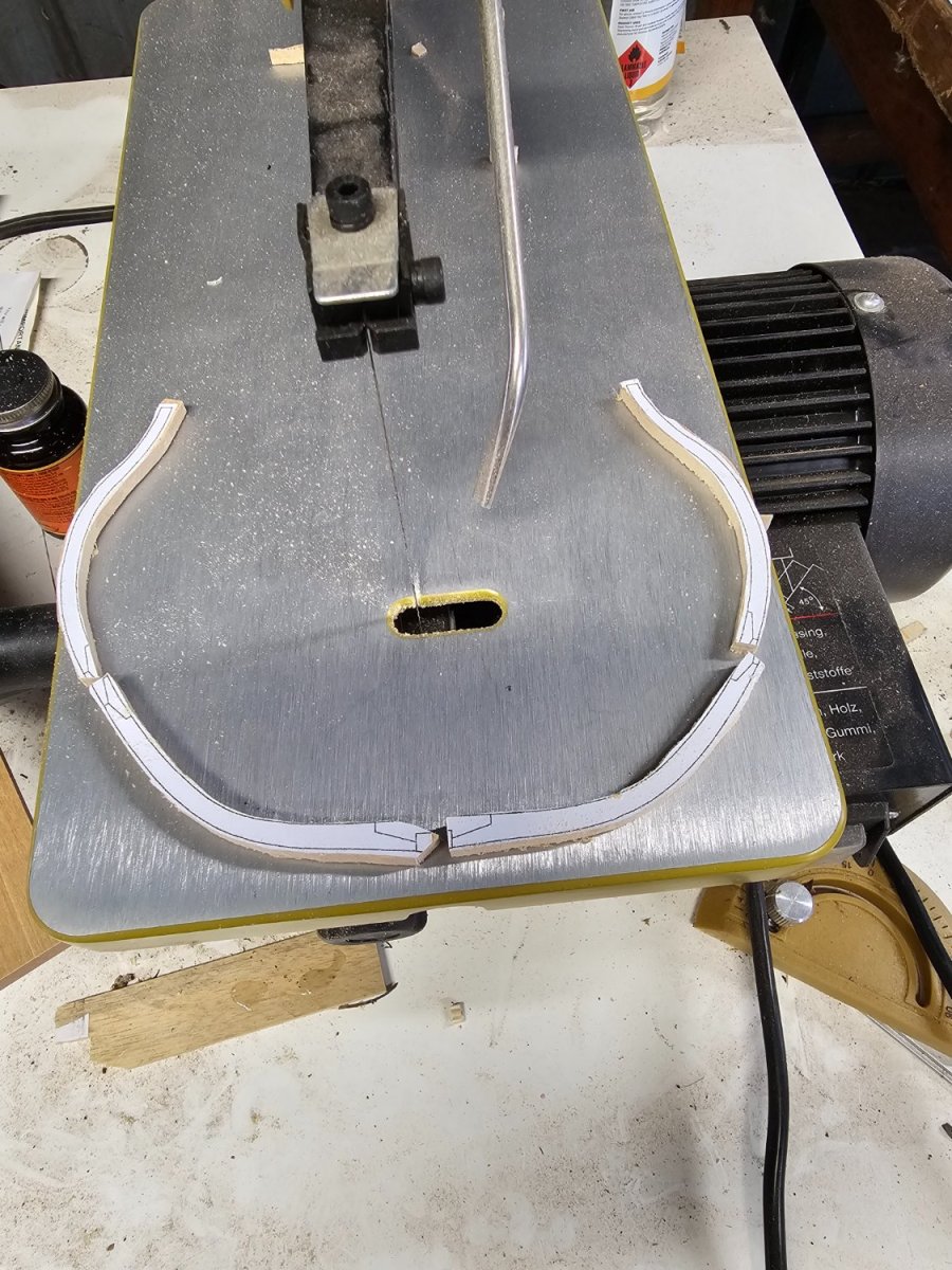
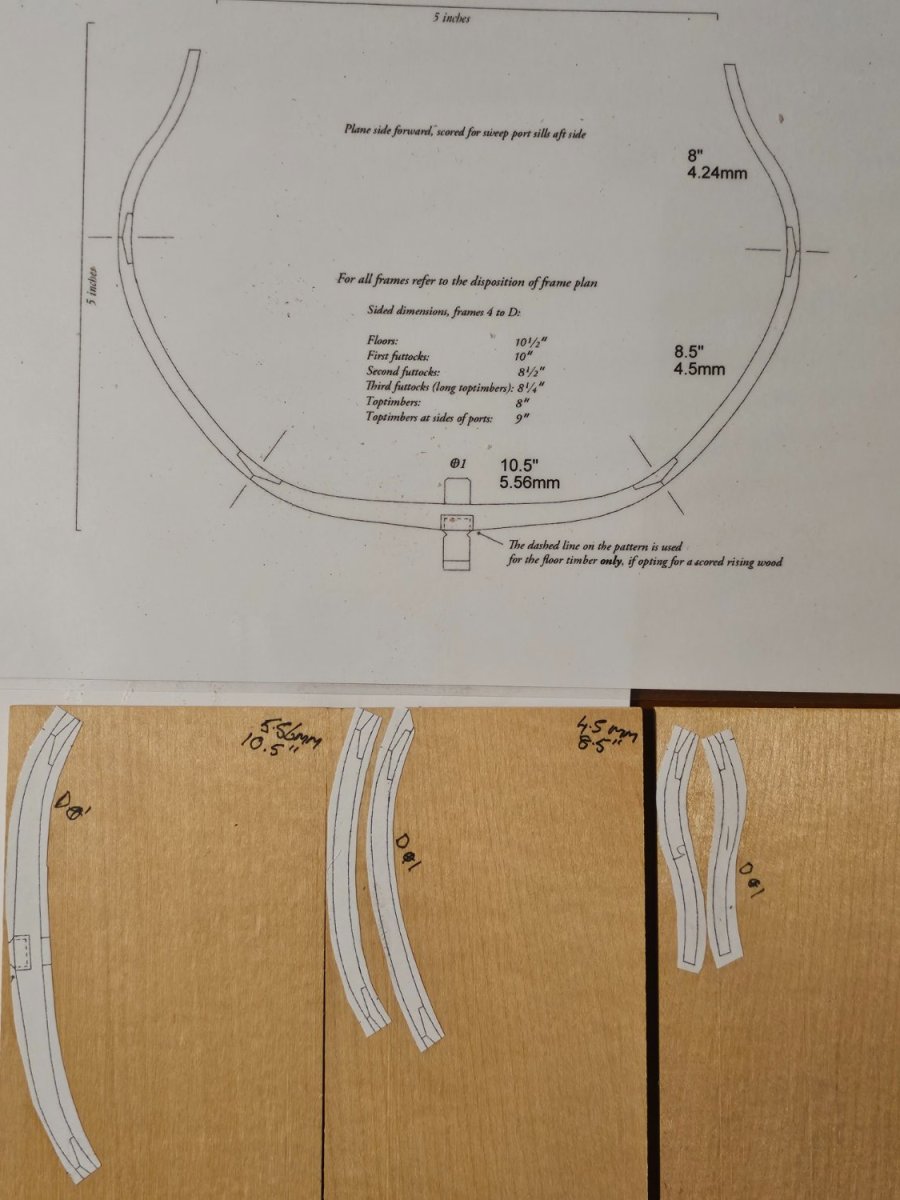
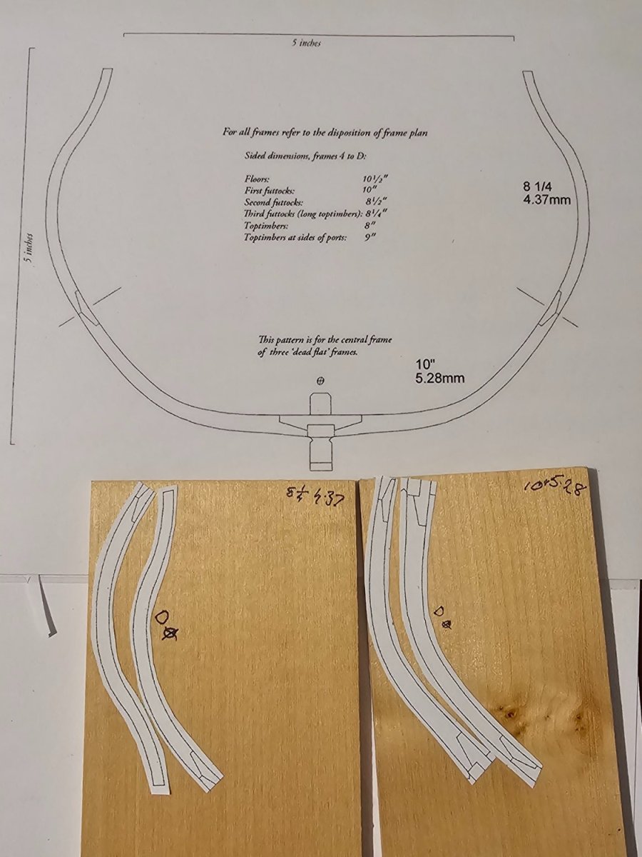
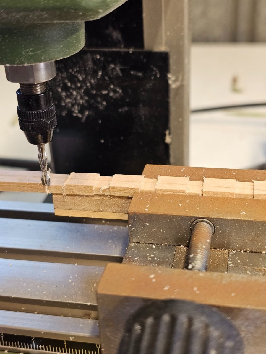
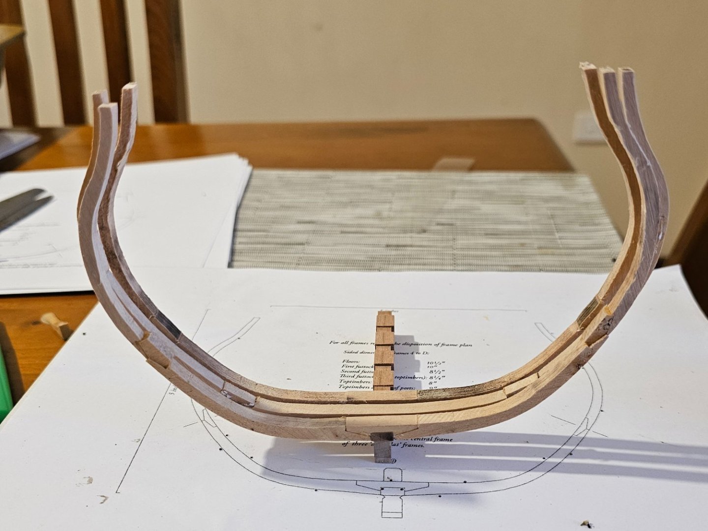
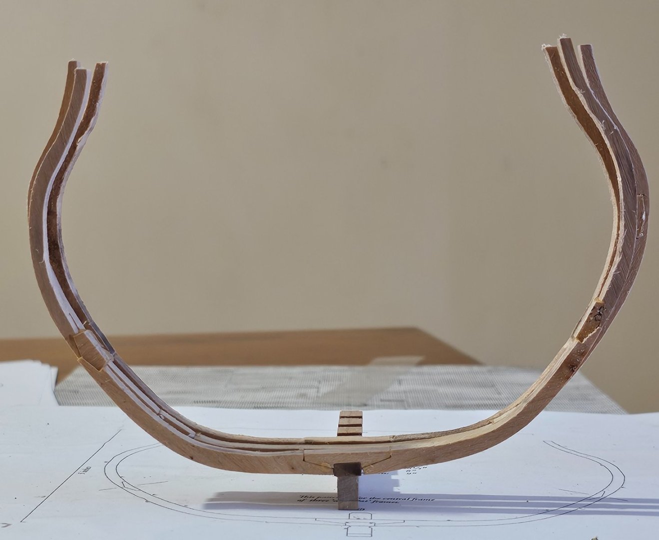
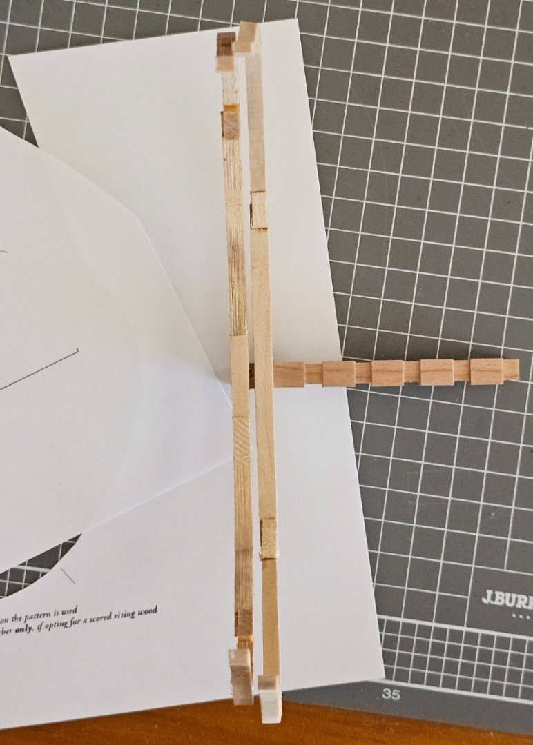
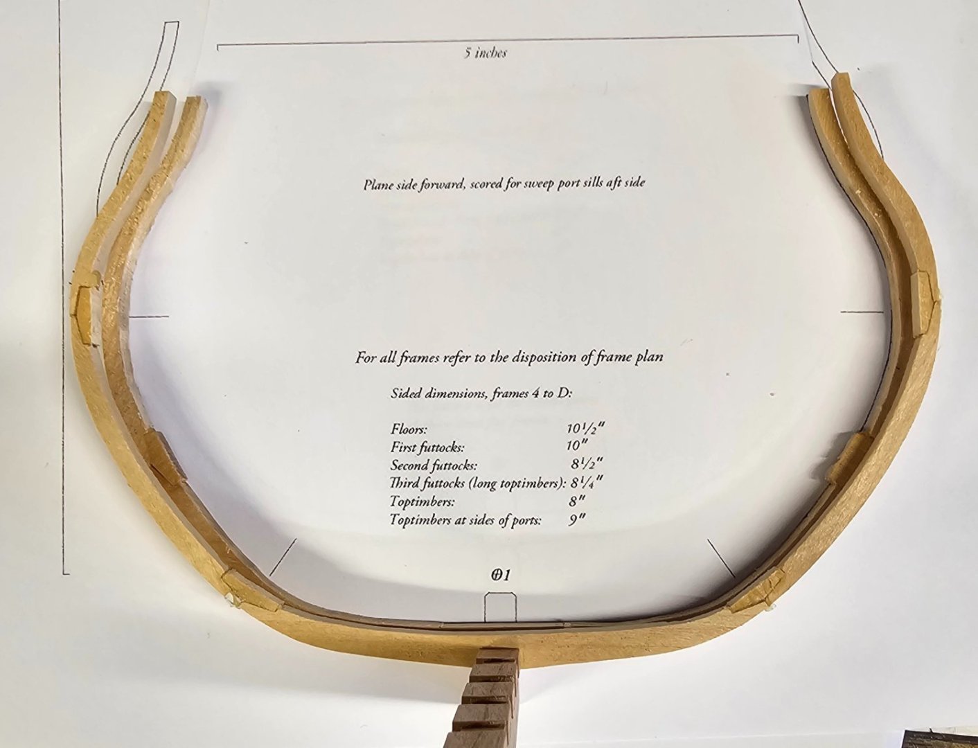
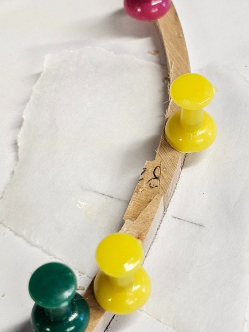
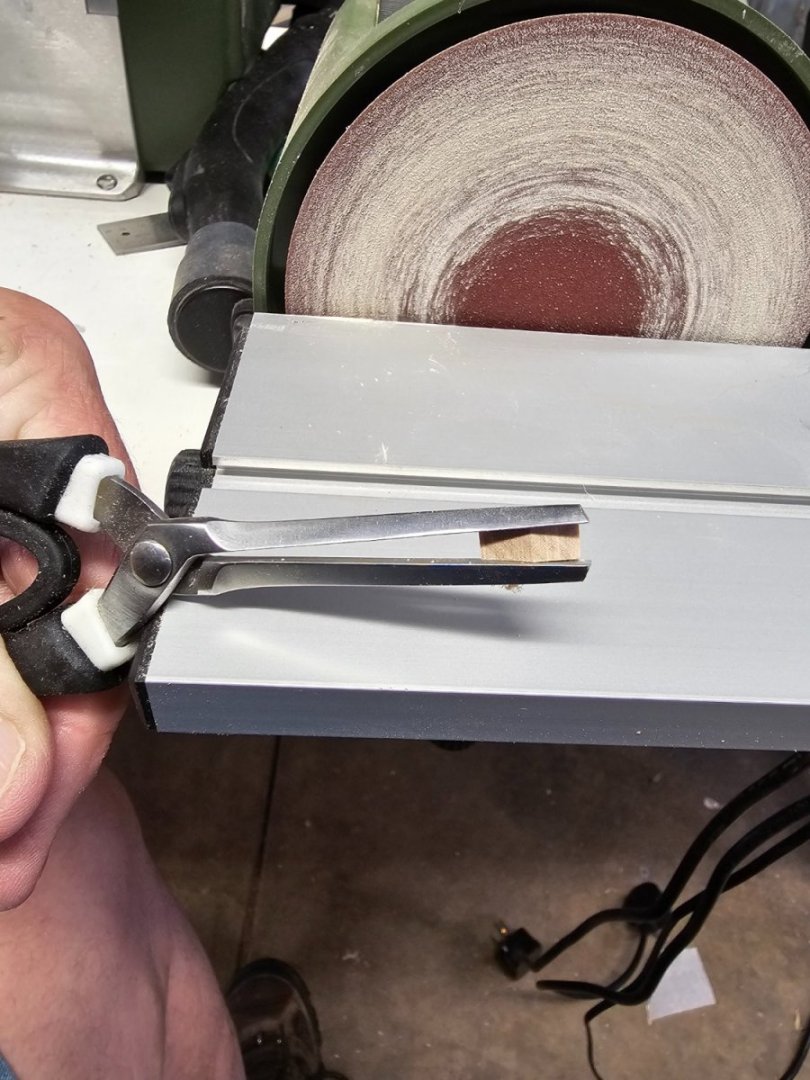
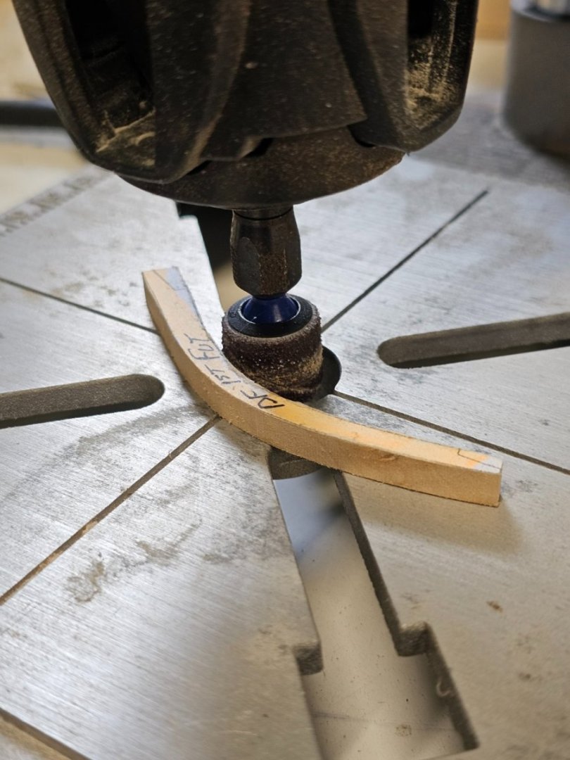
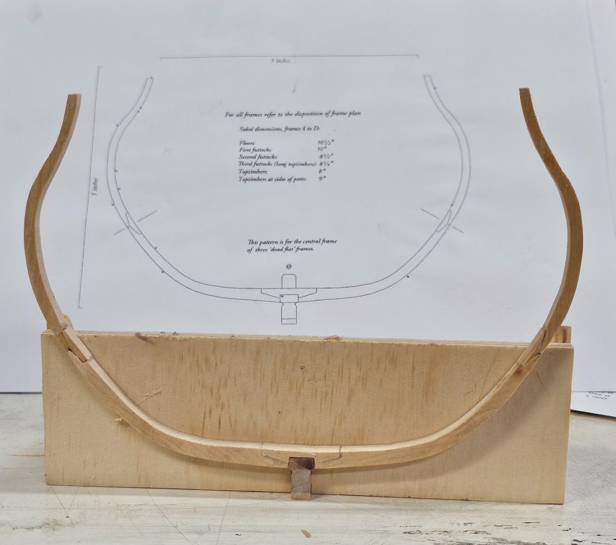
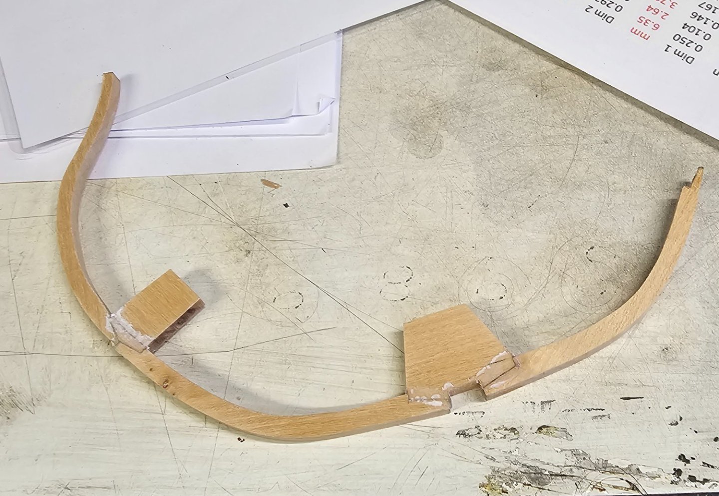
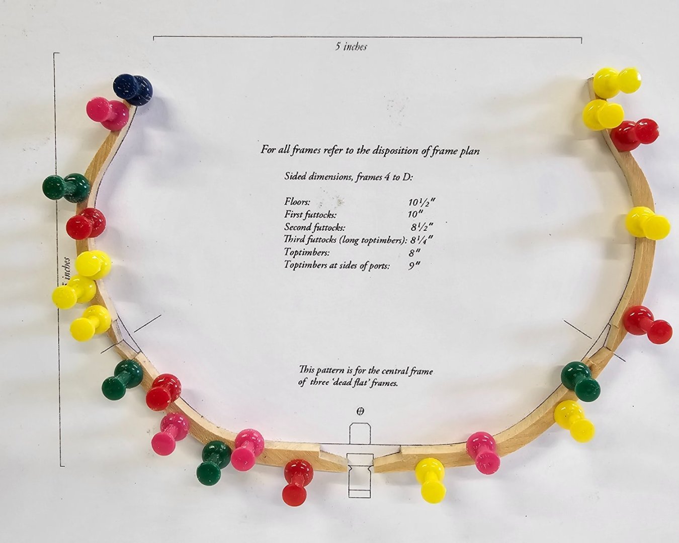
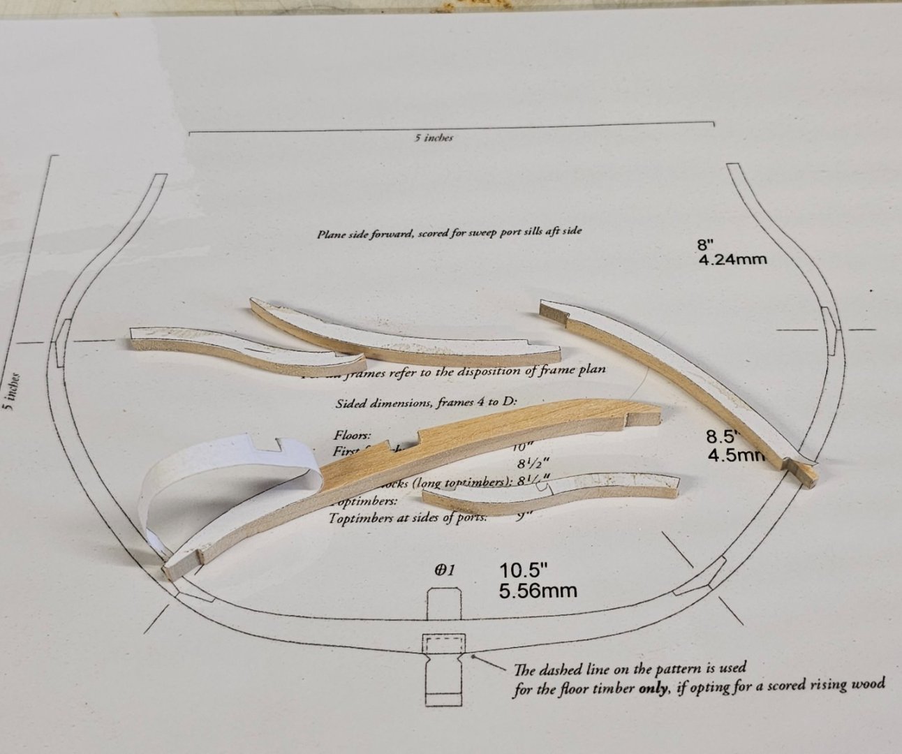
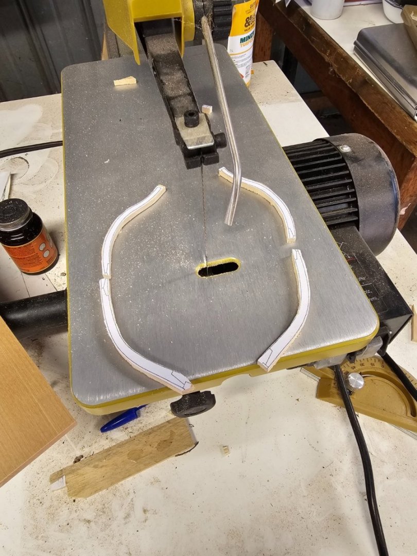
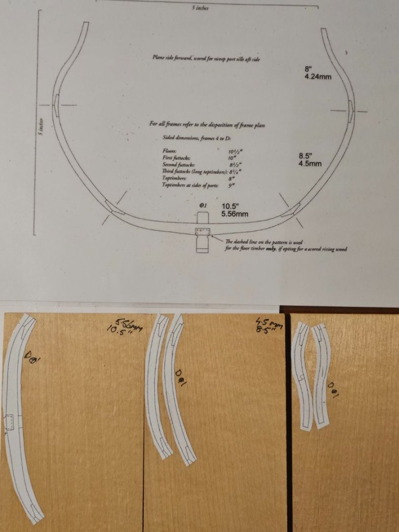
After a break of around 5 - 6 weeks, I resumed making frames. I needed to remake the dead flat. The dead flat #1 fit well and so was going to keep it. After making the dead flat again, I spent the last several days gluing it up. This time, I use my proxxon mill to cut the slots for the chocks. I am able to get square joints now instead of rounded. After I removed it from the jig, I placed it on the keel and placed the dead flat #1 on as well to check alignment etc. I was surprised to see the two were different at the top. After investigating, it seems the dead flat #1 has the top timbers moved outwards. If I spring them in around 1/4" each side, they fit the dead flat # 1 template. My workshop is in a garage which is not air conditioned. In South Australia it can get warm in the shed as well as cold in the winter. Any ideas how I can avoid this issue occurring over the 12 frames I need to construct? Elastic bands or hold downs of some sort to be applied to the top timbers as each frame is made? Bring each frame inside the main house once completed? In the 1st image, is having this many cut out likely to cause issues if I do not get to them all straight away? I realised I could you my dremel and stand to help me sand the inside faces of the futtocks. I now use my proxxon mill to cut the slots out. The cuts are far better than my manual cuts with a fret saw. I glued the template of the frame onto 18mm masonite. I then assemble the pieces with wax paper underneath the glued joints. I drill 1.1 mm holes next to the frames and push in 1.15mm pins. These lock the frames whilst gluing up and holds the joints whilst they cure. Once the frames are joined, I then make the chocks to strengthen the frames. I sized them to fit first and then used some PE pliers to hold then so I could reduce the depth of them. A chock ready for gluing. Glued in with titebond. Chocks are now glued in. The wax paper stops the glue sticking to the template. The bottom one fits the dead flat template perfectly. That was made today. The one on top (the dead flat #1) was made around 6 weeks ago. It fits the pattern IF it is pushed in. I suspect I have to remake this but how do I avoid this recurring? A top view of the issue. The far left one was assembled today.


-
John Murray reacted to a post in a topic:
HMS Thorn by Kevin Kenny - Swan class 1:48 scale - David Antscherl practium
-
John Murray reacted to a post in a topic:
HMS Thorn by Kevin Kenny - Swan class 1:48 scale - David Antscherl practium
-
G'day Kevin, Thank you for that. I need to try and sus some places out for this. I know it is asking a bit much but have you considered a video on this process? I am sure I am not the only one thinking the same. Else, are you aware of any videos showing this process. I know of normal woodmills that I follow doing this for large slabs, but small logs such as we use seem to be thrown away. Ah well.
-
John Murray reacted to a post in a topic:
HMS Thorn by Kevin Kenny - Swan class 1:48 scale - David Antscherl practium
-
Kevin, I am interested in how you process your coffeewood. I have you you have branches perhaps 6 to 12 inch diameter by a few feet long. I have similar except they are pear. I only have proxxon gear, how do you rip them for processing by your proxxon tools? Regards John
-
 John Murray reacted to a post in a topic:
HMS Thorn by Kevin Kenny - Swan class 1:48 scale - David Antscherl practium
John Murray reacted to a post in a topic:
HMS Thorn by Kevin Kenny - Swan class 1:48 scale - David Antscherl practium
-
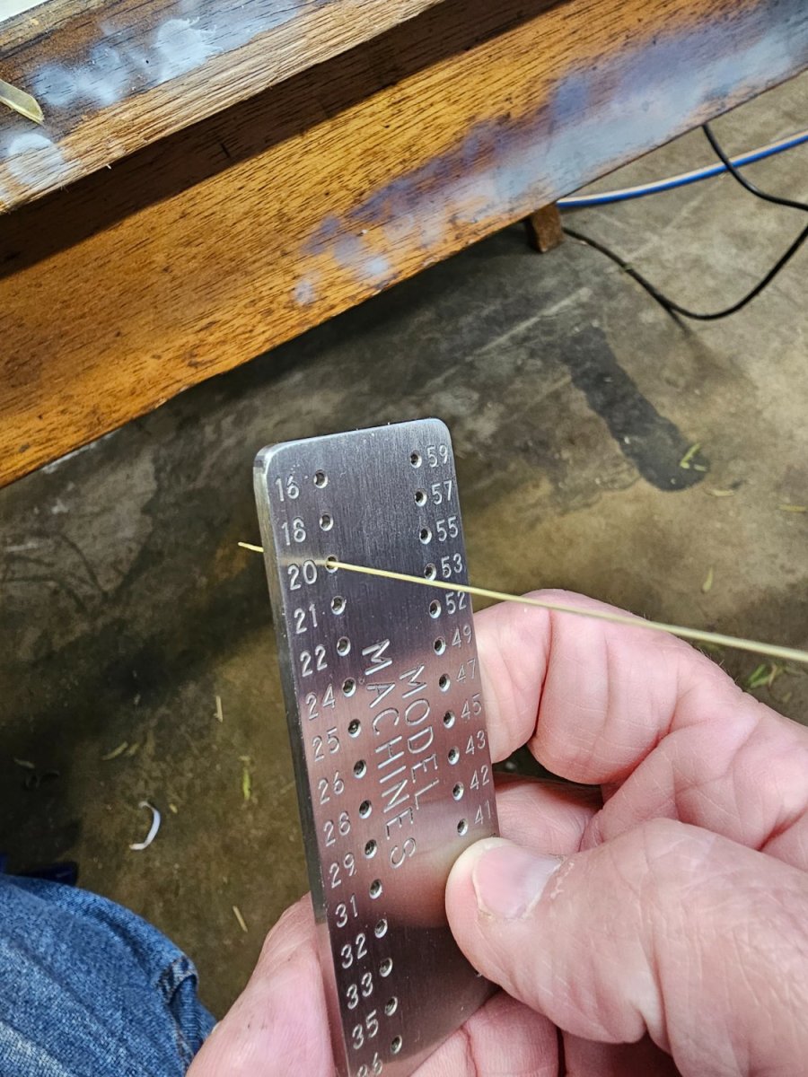
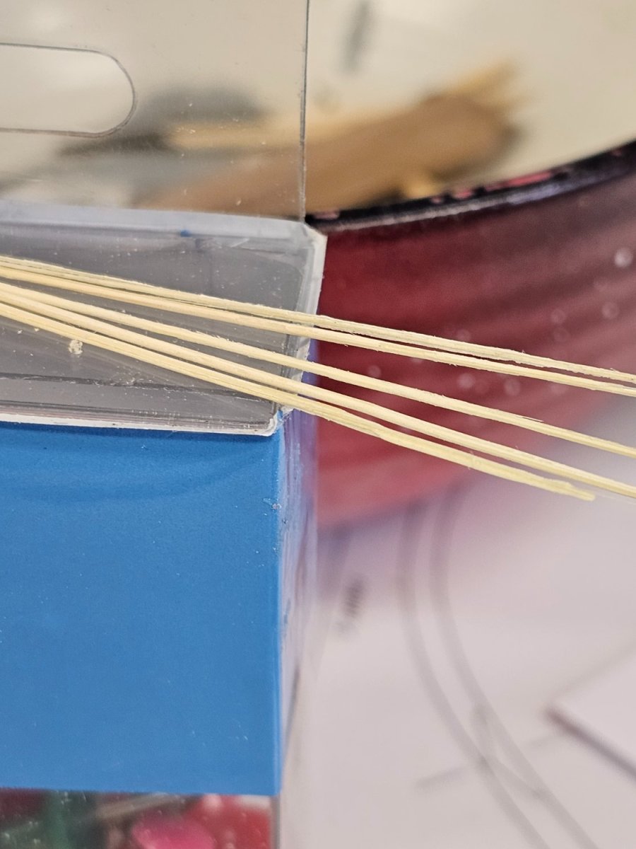
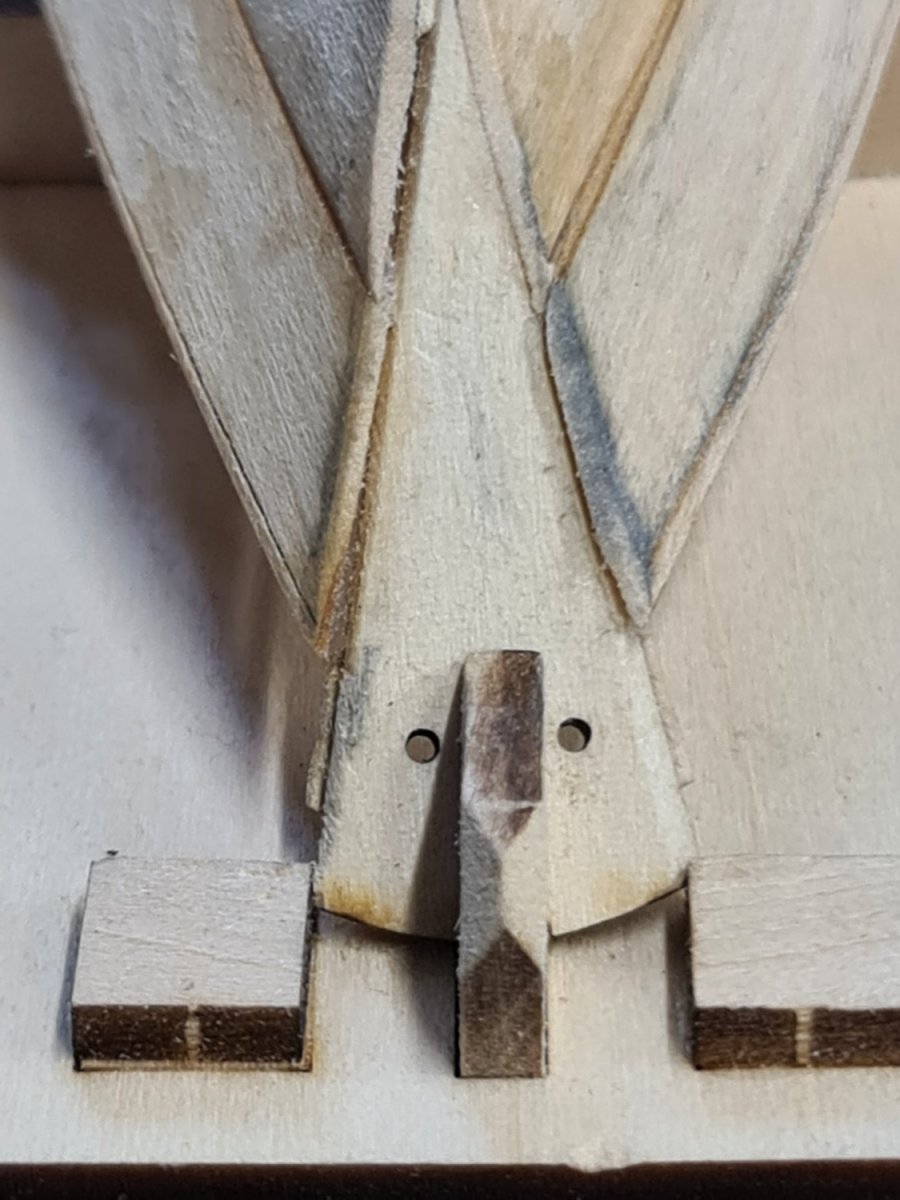
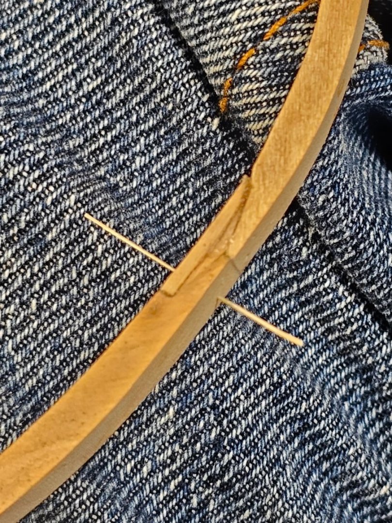
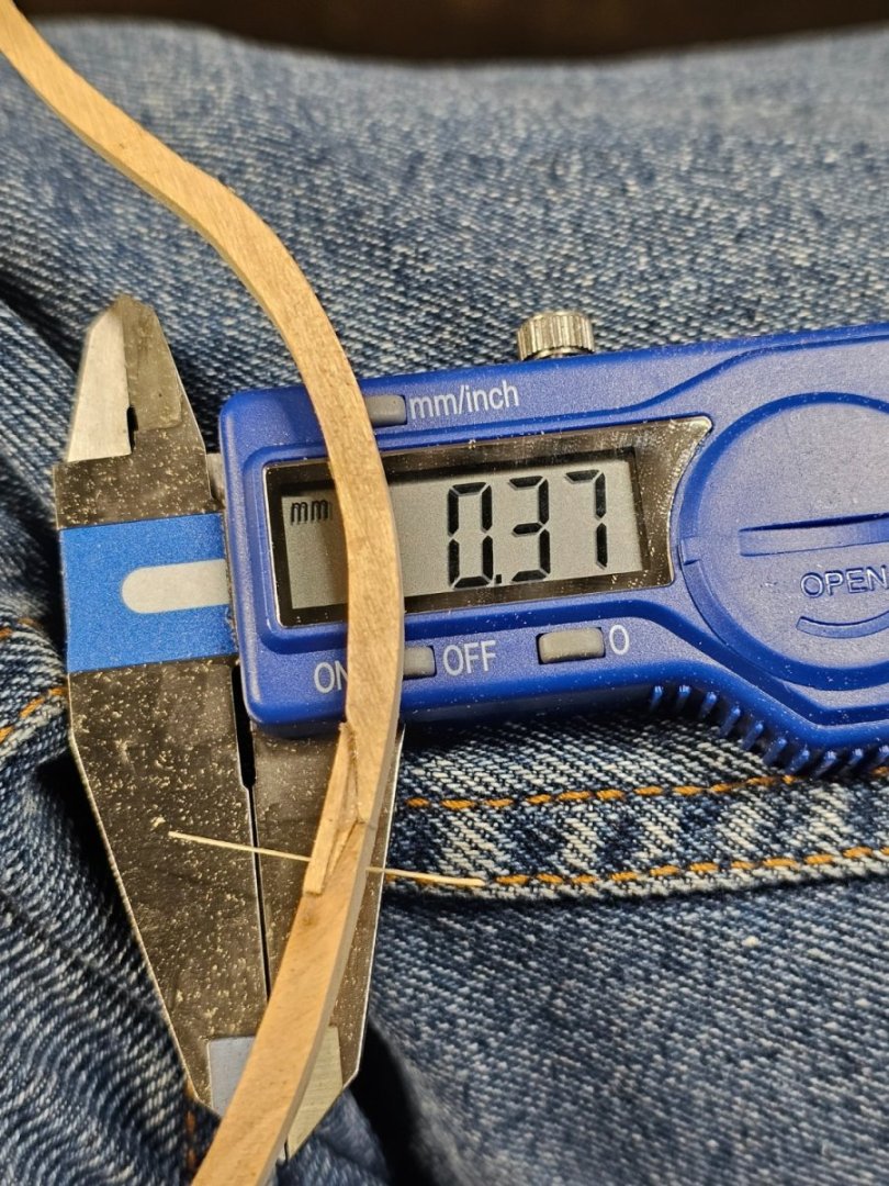
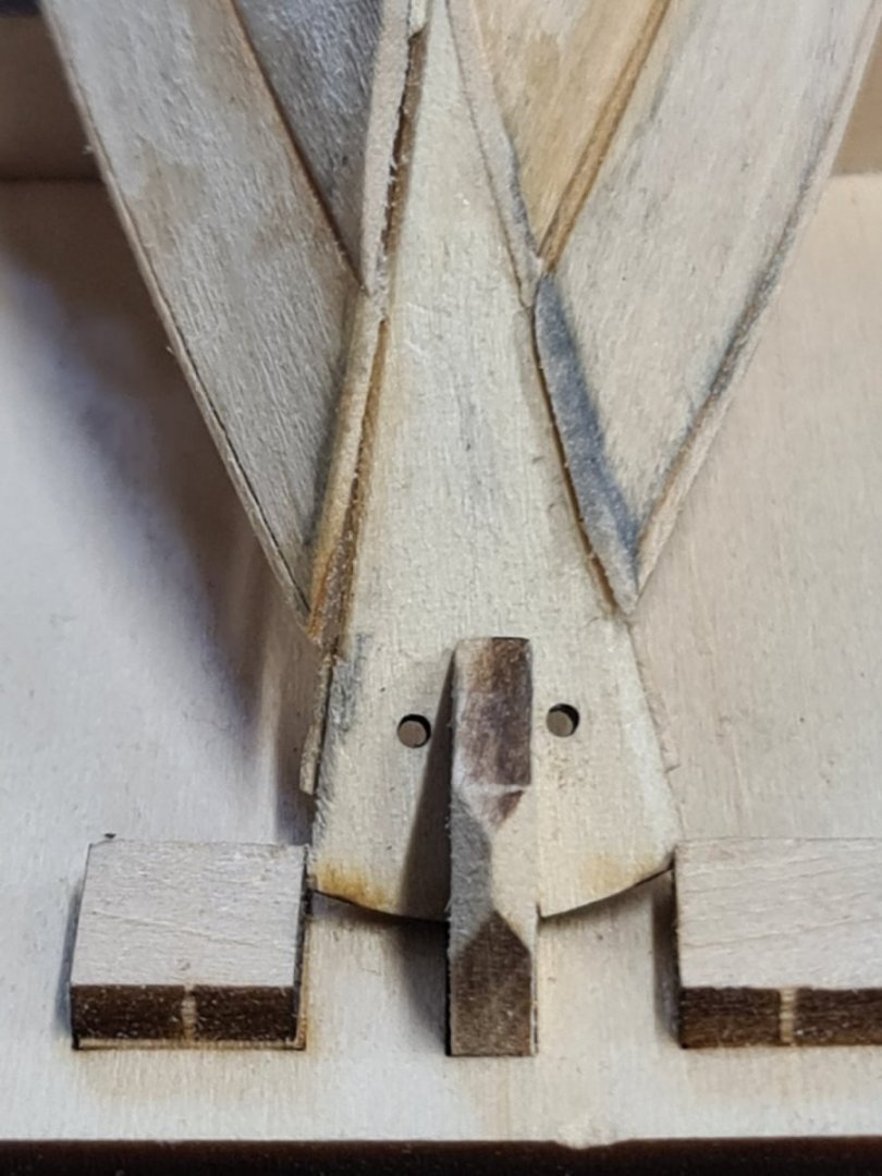
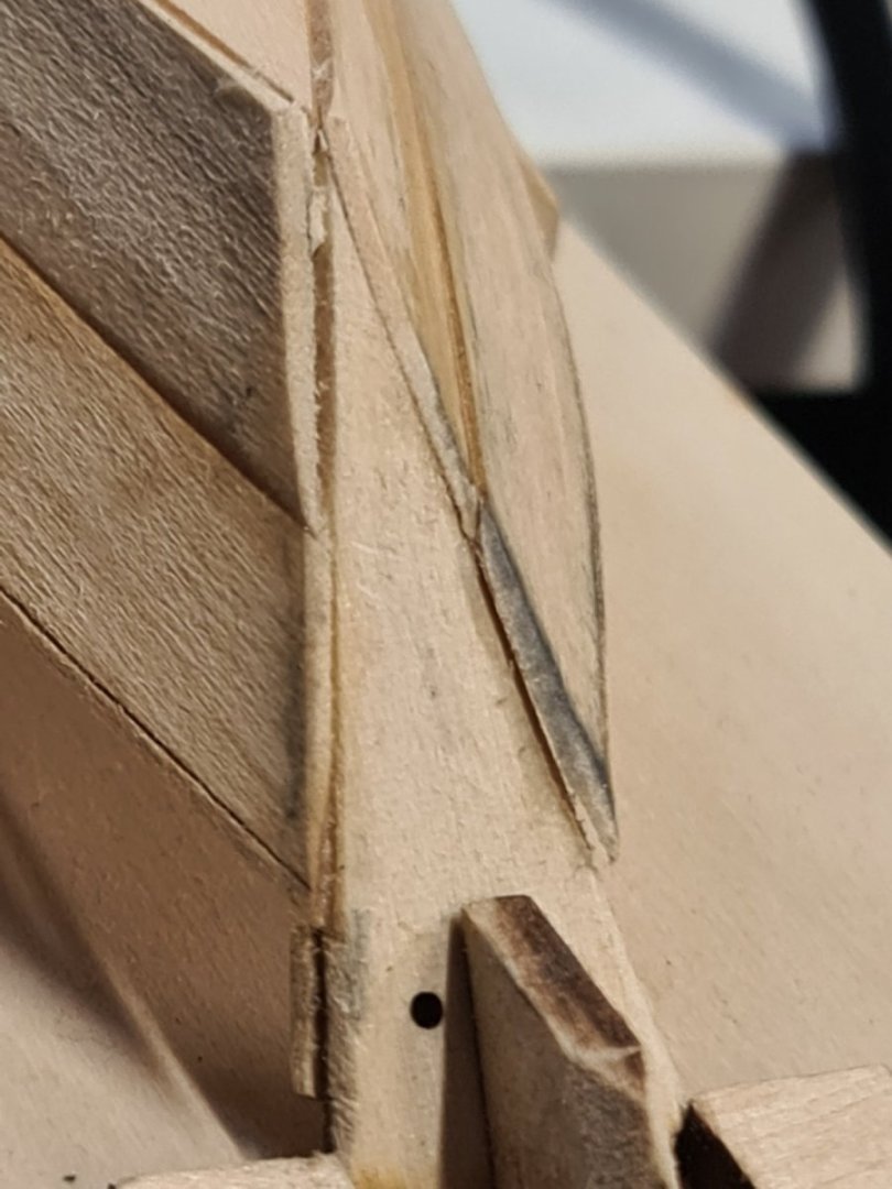
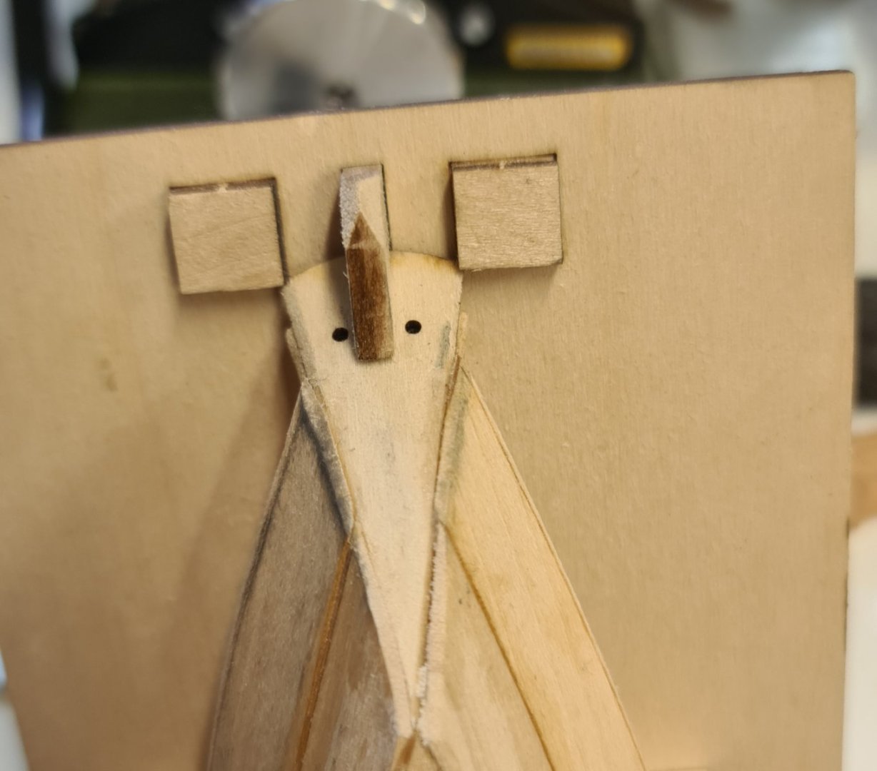
This afternoon, I started to make treenails for the joint of the cross section. I needed to get them to around 19 thou. I drilled the 4 holes in one joint and managed to insert the treenail. Unfortunately, I then snagged the top timber on my trousers which had it snap off along the grain near the joint. Ah well, I need to redo it now and will use this as a learning experience.


-
The last few days have been spent making the first frame. I have learnt some lessons here. I may use the frame and the keel as test pieces only. I used 5 minute epoxy which was problematic on one joint. I changed the reglue of the joint to PVA glue and let it sit for 24 hrs. The joint is better. I will get some Titebond II. I couldn't find my bottle from last yr so used the epoxy. Lesson learnt. I glued the frame printouts to 5mm foam board then pinned the pieces to it for gluing. The epoxy stuck to the foam board and was a mess to clean off. On the reglue of the one chock with PVA I used wax paper between the frame and board. That stopped the glued frame sticking to the board. peeling the paper off. The rubber cement made this easy. The dead flat #1 pinned over the outline. The joint below failed. The 5 minute epoxy was still soft after 24 hrs. 2 joints worked ok with the 5 minute epoxy. I need better clamping methods. None of my clamps were not suitable so this sufficed. Raising the frame for a test fit on the keel.


-
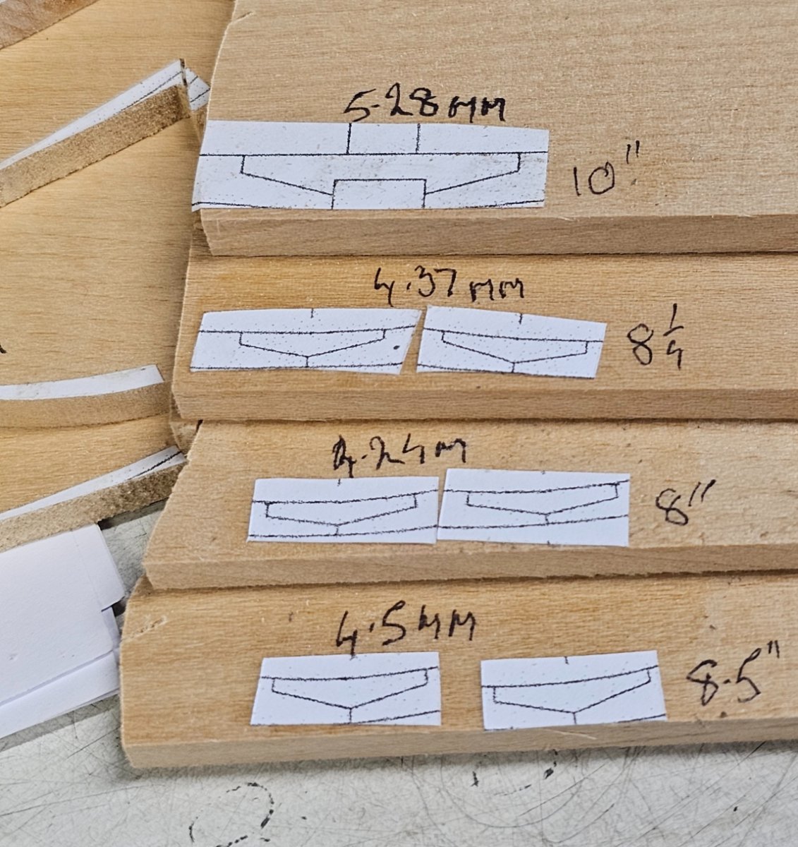
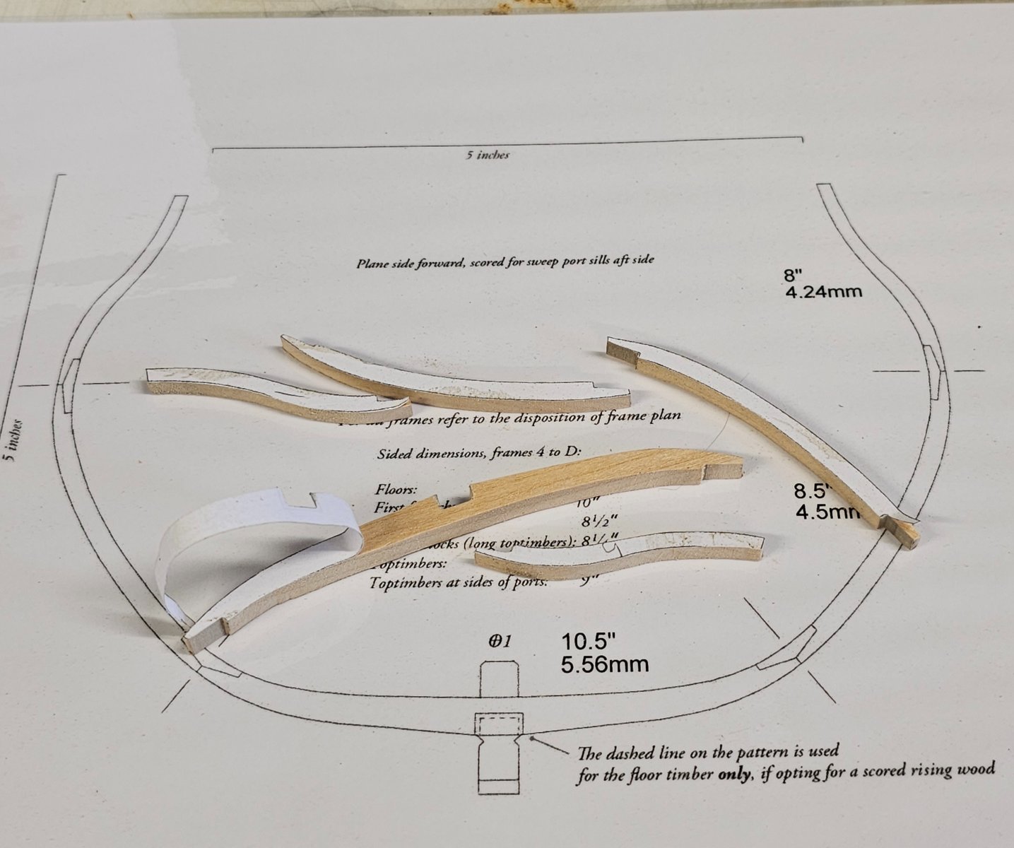
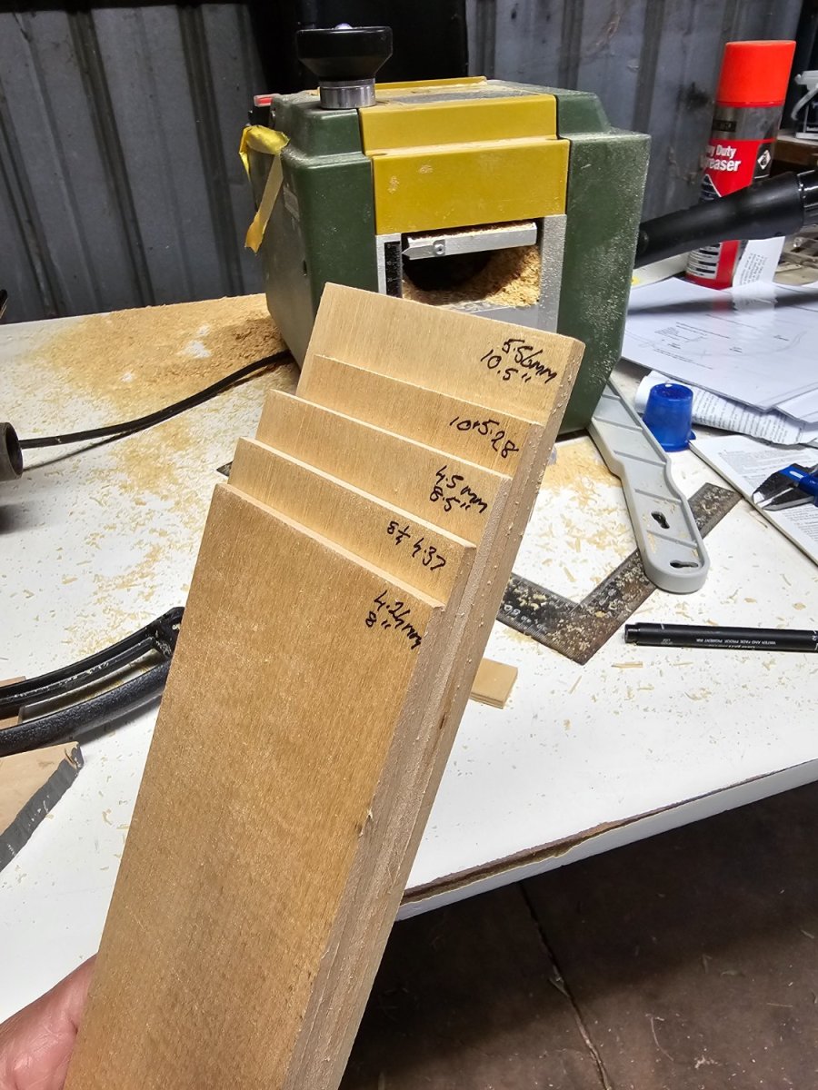
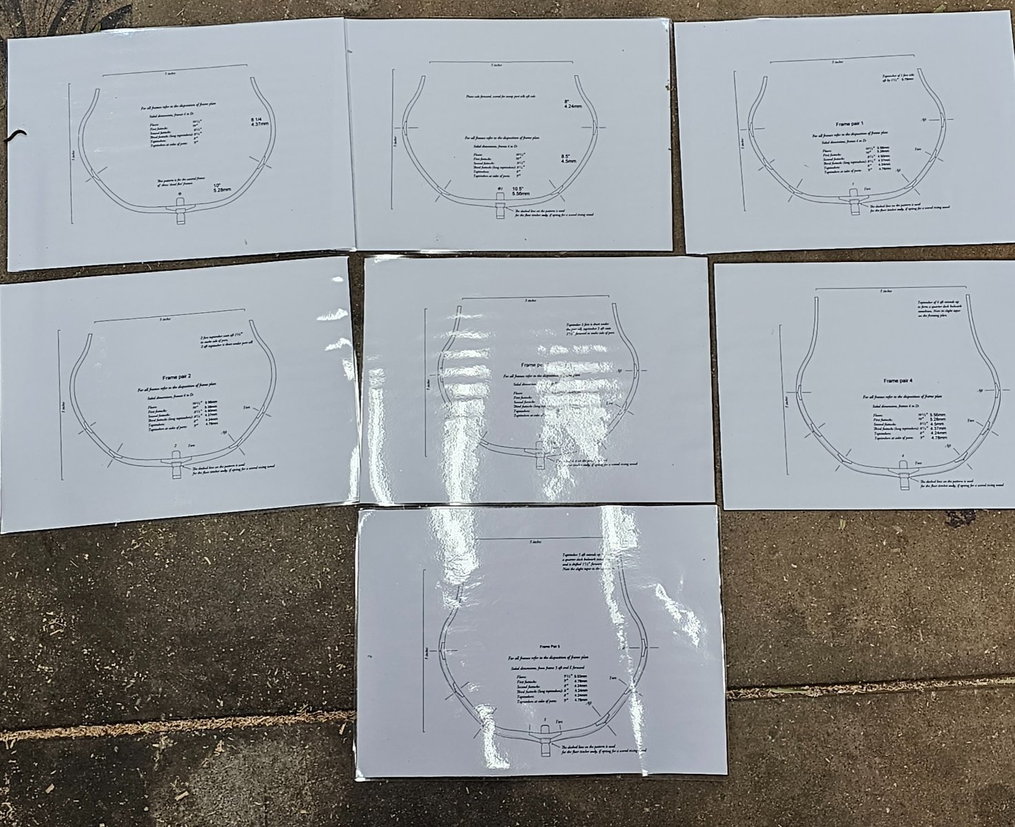
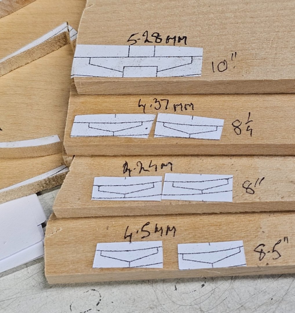
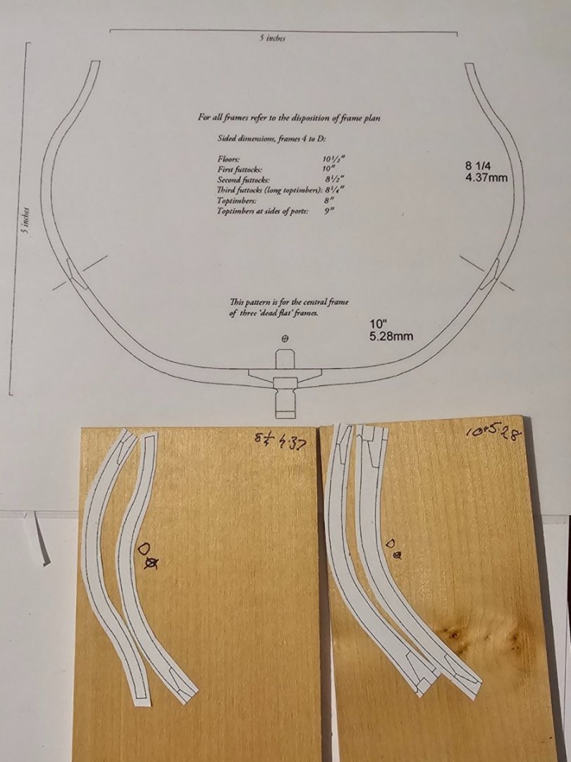
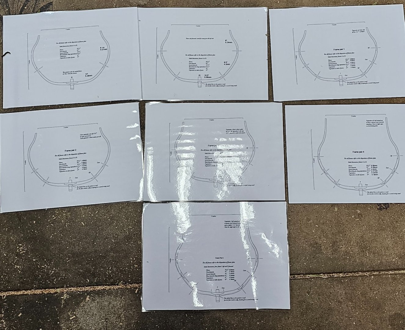
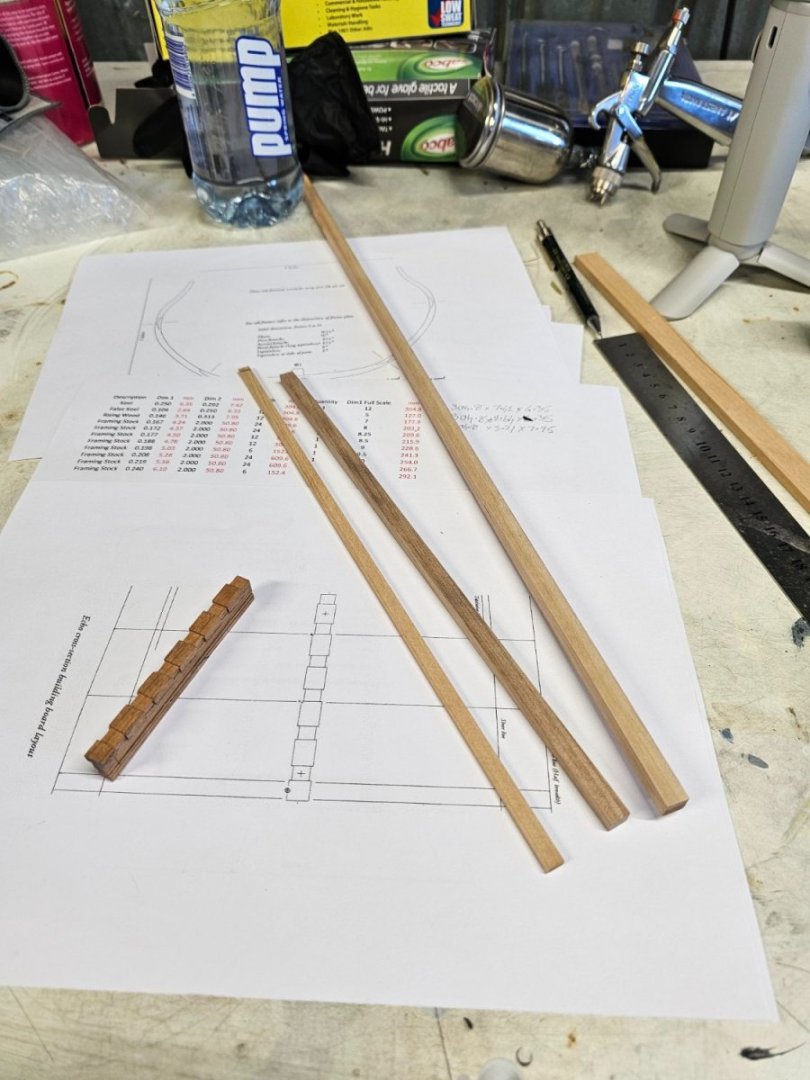
Today was spent getting things ready to cut the frames. I laminated the 7 sheets so I can assemble the wood pieces over the laminated frame with pins and glue. It won't stick to the plastic. I also planed down 5 planks of 10mm thick English Lime to the five thicknesses I require for the two dead flat frames. The five vary in thickness from 5.5mm to 4.2mm

-
I now will go and kick myself! I knew there had to be a pattern for the dead flat but obviously on the website, I kept missing the dead flat 1 pdf. I have only just seen it after you said there was a pattern for it. Thank you so much for that.
-
John Murray reacted to a post in a topic:
HM Sloop Echo 1781 Cross Section by John Murray - 1:48
-
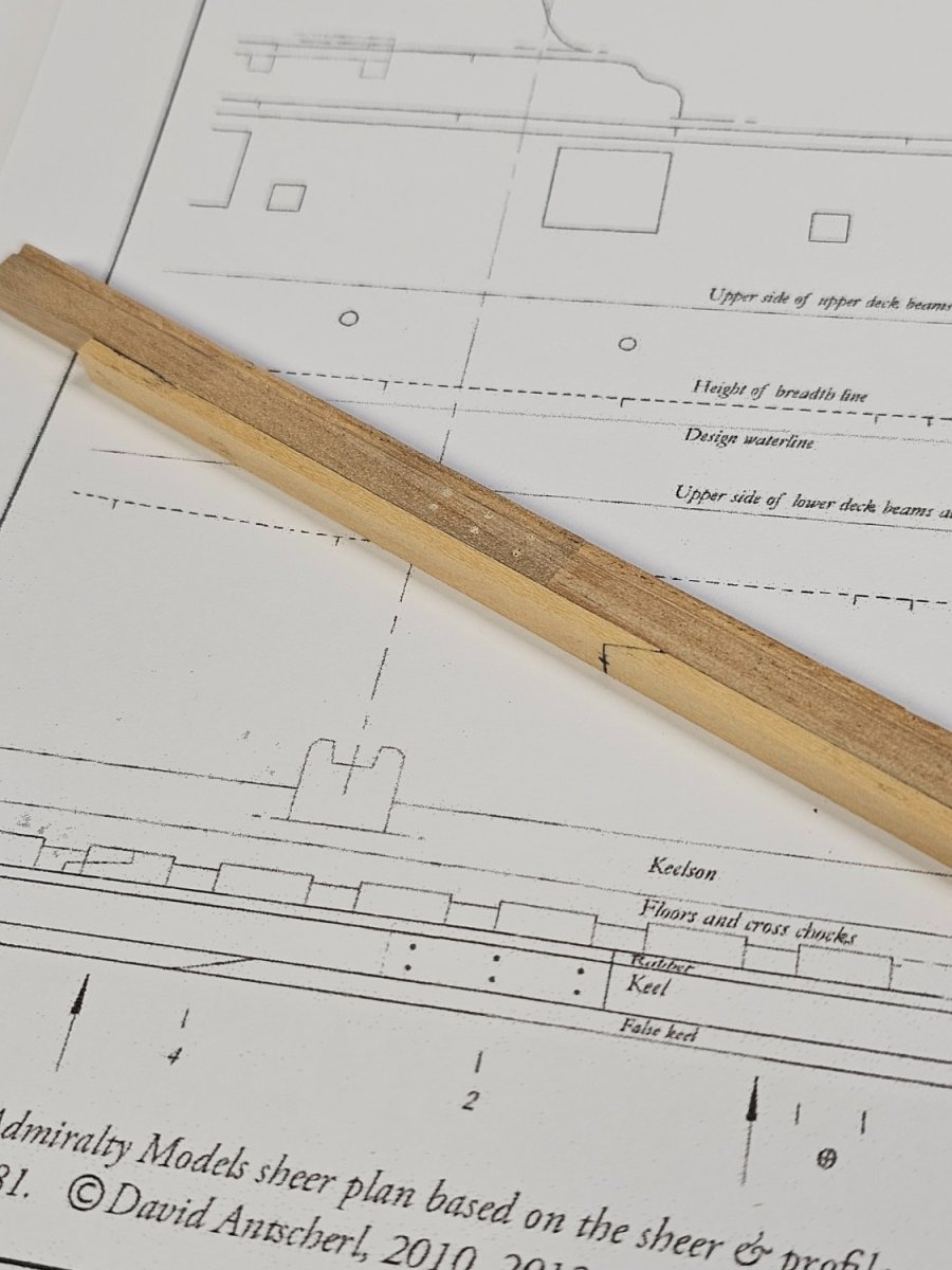
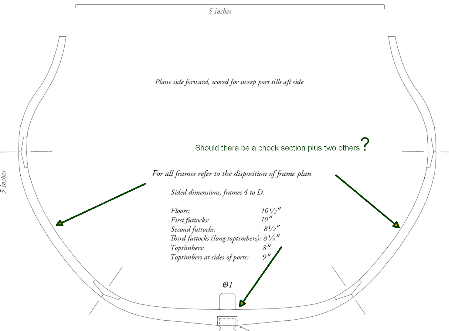
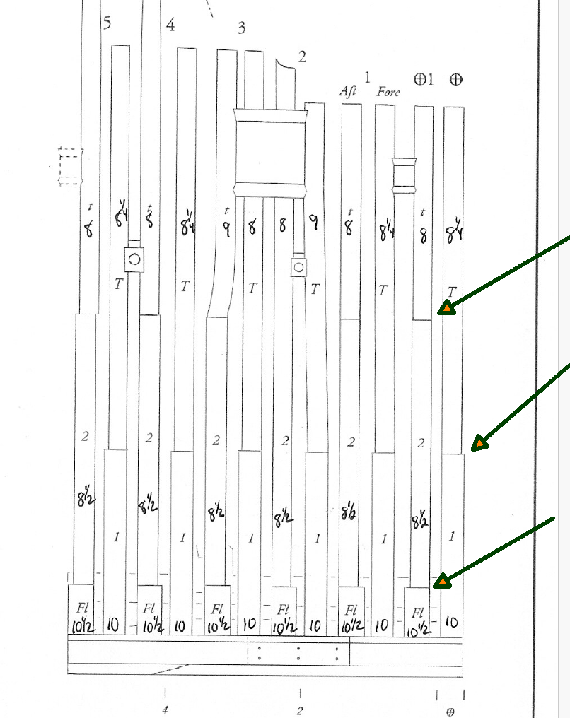
Last yr I made a trial keel of the HMS Echo cross section available at http://www.admiraltymodels.com/Tips.html I had life intervene but I want to start building the cross section. The last few days I have spent building another copy of the keel. It came out ok. Thinking about the completed keel I realise a few ways I could speed up the process as well as make it a bit more accurate in cutting the slots of the rising keel. Last yrs keel on the left, the new keel on the right. I have a question now that I am ready to start on the frames. The instructions call for starting on the dead flat available at http://www.admiraltymodels.com/Echo_frame__dead_flat__1.pdf My reading is that each frame comprises two sections, a fore and aft frame. All of the frame numbers have fore and aft indicated on the pdf except the Dead Flat. Yet, It seems that there are two distinct sets of futtocks for the 2 dead flats as shown in http://www.admiraltymodels.com/Sided_frame_dimensions.pdf I am not understanding this obviously so can someone point me in the right direction thanks?


-
That is what I am finding as well..👍
-
John Murray reacted to a post in a topic:
Grand Banks Dory by John Murray - Model Shipways - 1:24
-
After putting it off, I tried debonding the stems broadstrake planks. I used my electric plank bender to heat it up and I was surprised how it came apart. I have now left it tonight and will clean it up tomorrow. I will also ensure the stem is properly braced so it cannot move next time I glue the broad strakes in position.

-
48th Scale imperial rulers. Where?
John Murray replied to John Murray's topic in Modeling tools and Workshop Equipment
Thank you very much for your kind offer. Unfortunately, I ordered one and then read your offer... Doh!