RD111
-
Posts
8 -
Joined
-
Last visited
-
 wool132 reacted to a post in a topic:
US Brig Syren by RD111 - Model Shipways - 1:64
wool132 reacted to a post in a topic:
US Brig Syren by RD111 - Model Shipways - 1:64
-
bobandlucy reacted to a post in a topic:
US Brig Syren by RD111 - Model Shipways - 1:64
-
Dave_E reacted to a post in a topic:
US Brig Syren by RD111 - Model Shipways - 1:64
-
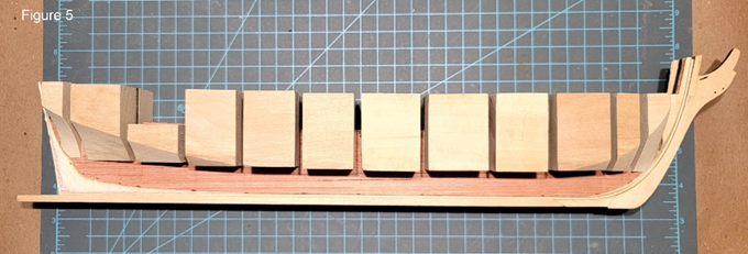
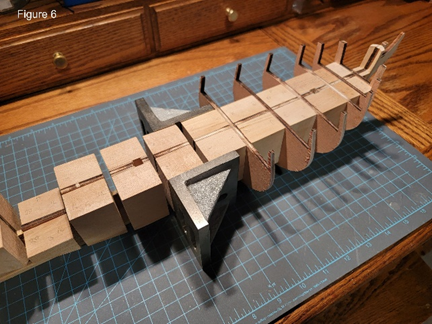
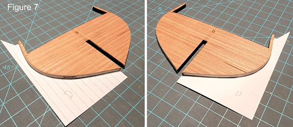
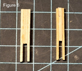
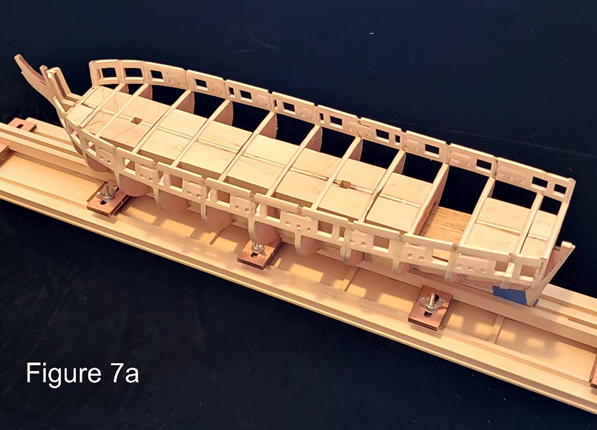
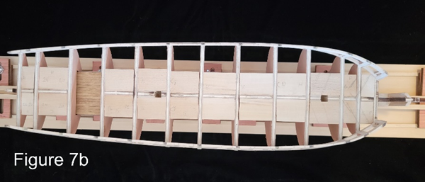
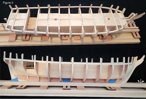
 Finally finished placing the port and starboard sills. To align the lintels, I made a 15/32” x 15/32” spacer using 3/16” x 3/16”, 1/16” x 3/16”, and 1/32” x 3/16” bass wood strips. All the strips were cut to 12”. The 1/16” and 1/32” strips were glued between two 3/16” square strips. This gave a thickness of 15/32”. The 12” length was cut in half. The two halves were glued together with 15/32” lengths of the 1/16” and 1/32” strips stacked as spacers. This made a 5/32” x 5/32” x 6” spacer, Figure 5. The 6” length was long enough to reach the port and starboard lintels at the same time. Before the glue set, the lintel inside surface was aligned to the inside edges of the adjacent bulwark stanchions. This minimized the amount of interior sanding required. After the lintels were permanently in place, I realized that basswood was placed with the 1/4" side vertical rather than horizontal. The result was that the lintel tops are higher than the bulwark stanchions. The 3/16” width was wide enough to get the proper curve at the bow, so I guess I am OK; plus, this required less sanding. Preliminary sanding was done using 60 then 100 grit sandpaper to reduce the thickness of the lintels to the thickness of the bulwark stanchions. My initial intent was to use the 15/32” spacer to align the gun port sides; however, as Jim (Oldsalt1950) stated, not all of the gun ports are square (Thanks for the reminder, Jim). Therefore, the spacer was split into two pieces that were 15/32” x 3/16” x 6”. The gun port side closest to a bulkhead was placed first. The 3/16” side of the basswood was aligned vertically and horizontally parallel to the bulkhead. After the glue set, the 15”/32” x 3/16” x 6” spacer was used to align the second gun port side to the first at the top and bottom. This process was used for all the gun ports except for the two most anterior gun ports. For these gun ports, the 3/16” bass wood sides were aligned as shown on the plans. The inside edges of the gun port sides were aligned to the inside edges of the sill and lintels to minimize interior sanding. The starboard side was done first. For the port side, the 15/32” x 3/16” spacer was placed in the starboard gun port, then aligned parallel to the bulkheads. This defined the positions of the gun port sides on the port side except for the two anterior gun ports. A similar process was used for the sweep ports using a 1/8” x 1/8” x 6” spacer to align the sweep port tops and sides. For the sweep port sides, 1/8” x 1/4” basswood was used instead of the 3/16” x 1/4” basswood. Final sanding was done using 100 grit sandpaper to reduce the bulwarks to about 3/32” and 1/8” at the top and bottom, respectively. Finish sanding was done with 150 and 220 grit sand papers. Initially, thickness was measured using a caliper; however, this proved to be too time consuming. To simplify the measurement process two thickness jigs were made: one for 3/32” and one for 1/8”, Figure 6. The jigs made measuring the thickness a very simple process. The final contours of the bulwarks were checked using the top half of the templates used to check the fairing of the bulkheads. Lesson learned: watch where you are sanding. Elmers PROBOND wood filler was used to correct areas sanded too aggressively: generally, just below the lintels. The Elmers worked much better than my previous wood filler, and it was on close out at Menards. Figures 7a and b show the finished framing of the gun ports and sweep ports. Next steps: Taxes then Chapter 4.
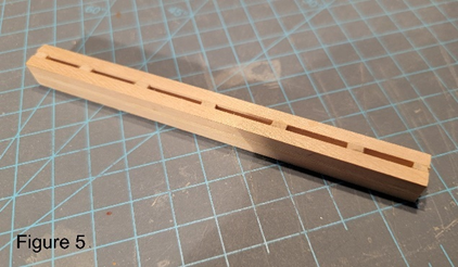
-
bobandlucy reacted to a post in a topic:
US Brig Syren by RD111 - Model Shipways - 1:64
-
Prowler901 reacted to a post in a topic:
US Brig Syren by RD111 - Model Shipways - 1:64
-
Overworked724 reacted to a post in a topic:
US Brig Syren by RD111 - Model Shipways - 1:64
-
Oldsalt1950 reacted to a post in a topic:
US Brig Syren by RD111 - Model Shipways - 1:64
-
Dave_E reacted to a post in a topic:
US Brig Syren by RD111 - Model Shipways - 1:64
-
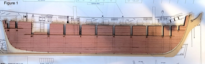
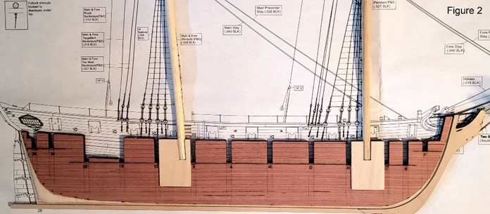
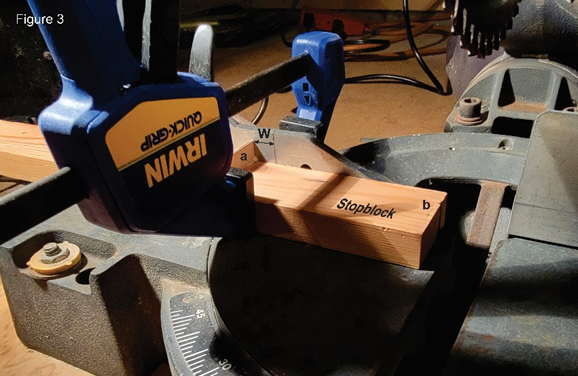
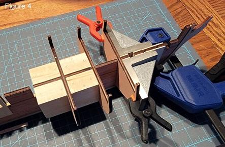
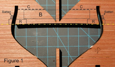
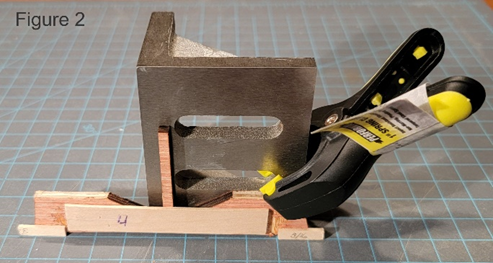
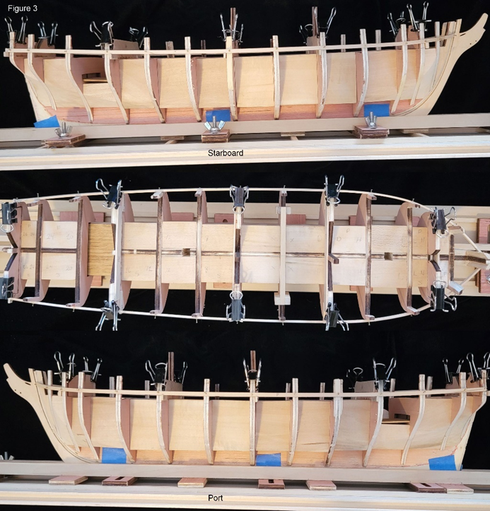
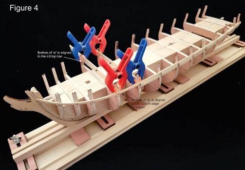
2/18/2023 After multiple attempts at aligning the port and starboard battens, I came to the conclusion that the marks on the bulkheads were not going to work for me. I needed reference points on which the batten could rest while it was being fixed in place. The reference points were made using scraps from the bulkhead sheets B and C. The section representing the deck and the inside of the bulwark stanchion was removed by cutting along line C, see Figure 1. The cut-out section was reinforced by gluing a 1/16” basswood support in region B. 1/16” basswood was used to make the two references, R, that would support the batten. After the glue had dried overnight, the reinforced section was clamped to a right-angle plate to hold it vertically while the refences blocks, R, were glued in place, Figure 2. It was important that the bottoms of the reference pieces were aligned with the lowest points of the deck and fell on a straight line (yellow line of Figure 1). Five bulkheads were selected to provide reference points: N, D, 4, 16, and 26. The heights of the reference blocks R were 13/64”, 25/128”, 3/16”, 23/128”, and 11/64”, respectively. The values came from a linear fit to the measure sill heights above the deck. Why I didn’t use 3/16” for all the references I don’t know. The jigs were held in place by clamping to the port and starboard bulwark stanchions, Figure 3. In theory, the battens should have been at the same height on both the port and starboard sides at the five reference points. In between, who knows. The shapes looked symmetrical by eye, but not perfect. At this point, I have had enough and decided to move forward. The bottom of the batten was marked on the bulkhead edges, and “horizontal” lines were drawn fore and aft sides of the bulwark stanchions using the port and starboard marks as reference. 3/2/2023 During the process of fitting sill pieces between the bulkheads, I discovered one reason why I was having so much trouble lining up the batten. While gluing the bulkheads to the bulkhead former, I did not notice that three of the bulkheads were not seated all the way. They were not off my much; however, it was enough to screw up the positioning of the batten. The net result was a lot of additional sanding to get the deck height the same across the bulkheads. After the sanding, the bottom of the batten was 3/16" above the deck at each bulkhead. When I set up the batten, I aligned it above the sill line rather than below it. The reason was that I could the use the batten to align the sill pieces. Additionally, I split a tongue blade in half, then shaped one end of each half to match the inside profile of the bulwark stanchions. The two tongue blade halves were used to define a horizontal line on each of the bulkheads between which the sill piece was to be placed, Figure 4. The two halves of the tongue blade, the bulkheads, and the batten defined the position of the sill piece during gluing. Completed the sills on both the port and starboard sides, Figure 5. After sanding, I found that the sill thickness was somewhat less than 5/32”.
-
CiscoH reacted to a post in a topic:
US Brig Syren by RD111 - Model Shipways - 1:64
-
Ryland Craze reacted to a post in a topic:
US Brig Syren by RD111 - Model Shipways - 1:64
-
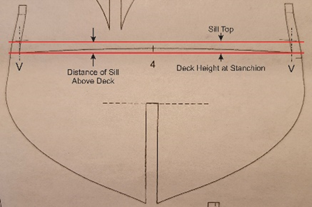
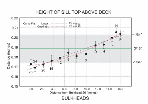
Based on comments, a good reference may be the distance of the sill tops above the deck base adjacent to the stanchion (V; Figure). As a retired scientist, I decided to see if Jim’s comment that the sill height is 3/16” above the deck base is correct. This was also proposed by Abelson (“the gun port sills are 3/16” above the top of the BHs: 1/16” for the plank. 1/16” for the waterway, and 1/16” for the swivel bracket”). To test this theory, distances were measured using a digital caliper for all of the bulkheads on both the port and starboard sides. Distances were measured using Sheet 3 Parts Template at three different sessions. During each session six separate measurements of the sill height were made for each bulkhead: three on the port side and three on the starboard side; or 234 separate measurements. There were two issues in making measurements using the Sheet 3 Parts Template. First, the thicknesses of the lines were different (Deck line thickness was 1/64”; Bulkhead sill mark thickness was 1/128”). This required using the centers of the line widths for the measurements. Second, accuracy of the templates, which is unknown. I assumed they accurately represented the bulkheads. Skipping all the boring details, for all measurements, the average sill height was 0.186” or 0.002” less than 3/16” (0.188”) with a standard deviation of 0.012”. This means that 2/3s of the sill heights varied less than 1/64” (0.016”) from 3/16”, and all were less the 1/32” (0.031”); therefore, assuming that all the sills are 3/16” above the deck is reasonable (good observation Jim and abelson). That said, the data indicates that the sill height gradually decreases from the bow to the stern by about 1/32” (0.031”): bow 13/64” to stern 11/64”, see graph. Overall measurement error was 0.012” or about 1/64”. Well, that was fun, but of questionable value. I guess it is time to start Chapter 3.
-
Thanks for the input. I originally thought that there was a uniform 3/16" height of the sill tops above the deck; however, when I checked the marks on the plans, this did not seem to be the case. The sill tops on bulkheads L, N, and P appear to be about 1/4" above the deck. I will be removing the battens and doing some localized adjustments of the fairing, then try again. Again, thanks for the input.
-
I considered getting the Amati Keel Clamp; however, while looking around I saw a reference to Doc Blake's Keel Clamping Tool. This actually looks better than the Amati clamp, and it can be built for less than half the price. Chapter 3 has me stopped. Alignment of the cannon ports appears to be critical. After adding the battens following the bulkhead marks, there were significant differences between the port and starboard sides. Adjustments were made to smooth the curves of the battens and make the two sides symmetrical. Eyeballing the curves, they looked similar, but not identical; therefore, it’s clear that I need some reference to determine which batten has the better shape. It is also clear that I need to do more sanding to improve the bulkhead fairing. Understanding that the heights of the battens on each side of a bulkhead should be the same from some reference, the question stopping my progress is what is a good reference? Any help or suggestions are greatly appreciated.
-
Thanks for the information. This seems to be a method used by many. It is relatively inexpensive and simple. My last modification to the Fair-A-Frame to fix the loose screw problem work to hold the keel; however, there still is instability laterally and I am afraid that something will break during construction. I am following your build and am just starting Chapter 3.
-
Before gluing the bulkheads, I needed to build a keel holder because my angle plates would no longer work to hold the model. A few years ago, I purchased the Model Shipways Fair-A-Frame Building Jig on sale. After putting it together I found it very difficult to mount the Syren and unstable. Modification suggested by others improved the stability; however, it was hard to mount the model because the screws moved when I tried to tighten them. Before making further modifications to correct this problem, I thought it would be worthwhile to ask what other methods are recommended for holding models during construction. There seems to be a lot of different methods in the build logs. Suggestions would be greatly appreciated.
-
A few years ago, I purchased four Model Shipways kits plus boxes of spare parts. Why I purchased these, I don’t know. Maybe, it was related to the “Pirate ship” I saw at a friend’s house when I was eight. It was the most fantastic ship I had ever seen. The detail was incredible. My friend said that his dad had built it. That experience started my model building era. My first attempts were simple wood boat and plane kits. This led to rubber band powered airplanes, then as I got older, gas-powered control line airplanes. Since I could not control them, it tried gliders. These were great except they seem to continue to glide out of sight. Finally, I tried radio-controlled boats (I skipped radio-controlled airplanes because they crash). The last models I built were Sterling models of the USS Missouri and the Chris Craft Corvette. That was 60 years ago. Brushing the dust off the various boxes, I decided to build the US Brig Syren (Model Shipways Syren kit MS2260). Mainly because it had the most readable/detailed instructions. Reviewing the manual, it became clear that this was not a model for a beginner. After some research, I decide to buy the Model Shipways Wooden Boat 3-Kit Kombo to see if I still had the skills to tackle building the Syren. In October (2022) I completed the last of the three kits. They looked OK to me; therefore, I decided to give it a go. During my research phase, I ran across this website, and decided to join. Reviewing the build logs, I found over 50 that had, or were, building the Syren model. Skimming through these logs I became aware of many issues associated with building this model and a significant amount of knowledge available on the site to deal with these issues. The question I had was whether to start my own build log, or just read those that were already posted. Without answering this question, I started building the Syren in November (2022). I kept waffling on the question until recently when I saw three new Syren Build Logs posted. Why not a fourth? So, here I am. Started the build on November 19, 2022 by reviewing the contents and verifying that the kit was complete, and that all parts were in good usable condition. I plan to follow the instruction manual included in the kit (Modeling the US Brig Syren 1803 prepared by Chuck Passaro); plus, comments from the Build Logs on the Model Ship World web site. Completed steps to date: 1. The bulkhead former was lightly sanded using 150 grit sandpaper. Only the loose laser char was removed. I read that removing the char does not necessarily improve the glue bond. This was tested by gluing two scrap charred edges together using Elmer’s Carpenter Glue. After the glue had set over 24 hours, I separated the two pieces. The fracture surfaces were nonhomogeneous, meaning parts of one piece were still attached to the second piece, which indicates a strong bond. 2. Contoured the 3/32” x 1/16” basswood strip to the bulkhead former and glued in place using Elmer’s Carpenter Glue. Also, glued the stern 3/32” x 1/16” basswood strip and the 3/16” x 3/16” basswood strip keel. 3. Used French Curves to draw the beard line on the port side using the burn through marks for alignment. Carved the rabbet from the port and starboard bearding lines as described in the manual. Sanded as best as I could. 4. Before starting on the bulkheads, the bulkhead frame was modified by adding slots for the masts. Several build logs described doing this by transferring the orientation of the masts to the bulkhead former using the provide plans. An analysis of seven builds that predrilled mast holes found a significant variation in the placement of the mast slots in the bulkhead former. The distance of the center of the mast from the bottom stern edge of the #8 bulkhead slot ranged from 3/16” to 3/8” with an average of 5/16”. One possible cause for the differences may be that the plans are scaled slightly smaller than the actual model. Because the builds had good results, it seems that any offset between 3/16” to 3/8” of the mast slots should work. Mast angles were determined using Syren Sheet 4 – Inboard plan, Figure 1. Decided to use a distance of 9/32”. As done by others, I used 1/16” basswood to box the slots, Figure 2. 5. Removed all the bulkheads and tested them in their slots. All were relatively loose. Decided to use spacer blocks rather than shims to stabilize the bulkheads and to make sure the bulkheads are aligned at right angle to the bulkhead former. The filler blocks were made from 1” x 2” basswood. Because I wanted to test the symmetry of the bulkheads (suggested by Frank Mastini; Ship Modeling Simplified) after fairing, the bulkheads were not glued in place while making the filler blocks. Prior to cutting the filler blocks, the distances between the different bulkhead slots were measured several times using a caliper. Within 0.01”, several bulkheads were separated by similar distances: L→N, N→P, 24→26: 9/16” (0.55”) D→H, H→L, 4→8, 8→12, 12→16, 16→20, 20→24: 1 5/16” (1.30”) X→D, 4→X: 1 ½” (1.50”) To cut filler blocks of similar widths, a stop block was added to my 10” miter saw (Figure 3). The width of the block (W) was set by measuring from the black vertical line on the miter saw fence to the vertical stop (a) on the stop block. When “a” is aligned with the vertical black line, the edge “e” is at the saw blade. Before cutting any fillers, the horizontal and vertical cuts of the miter saw were verified to be right angles. Filler blocks were cut slightly oversize, then sanded to fit using an inexpensive disc sander (purchased at Menards). For each of the three filler block widths, a first pair of blocks was cut and tested between the two appropriate bulkheads. After the width was verified, the remaining blocks of the same width were cut and sanded to fit. To align the bulkheads, I used a method similar to that shown in a figure in the builder’s log of US Brig Syren by Rafine. I ordered two 3” x 2 ½” x 2” slotted right angle plates from Amazon (cheapest I could find). Starting with bulkheads X and D, one right angle plate per bulkhead was used to align bulkheads X and D to the bulkhead former. The distance between the two bulkheads was measured at the bulkhead former and the port and starboard edges of the bulkheads to insure they were properly aligned. Two filler blocks were cut slightly oversized from the basswood. The cut edges of the blocks were sanded until they fit snuggly between the two bulkheads, then glued in place. For the remaining filler blocks, the appropriate bulkhead was aligned using both of the right-angle plates, Figure 4. In my hurry to finish the filler blocks, I neglected to do preliminary shaping of the filler blocks that extended beyond the bow and stern bulkheads. A Dremel tool with a double cut tungsten carbide burr was used to do the bulk reduction. Final contours were achieved by sanding using sandpaper grids of 60, 100, and 150, Figure 5. 6. The bulkheads were not glued in place; therefore, they could be removed as desired during the fairing. When in place, the bulkheads were very stable and did not move significantly during the fairing. To simplify the process, bulkheads X through P were faired together, Figure 6, followed by 4 through 26, then D through 8. By doing the fairing in sections, it was easy to hold the bulkhead former during the sanding. It also helped avoid breaking the thin extensions. Unless you drop it, which I did, resulting on one broken extension. This was glued back in place, and reenforced with basswood. I also learned not to sand the bulkheads using a bow to stern motion as this removed some of the wood from the bulkhead; especially in the extensions, Figure 6. 7. At the completion of the fairing, the contours of each bulkhead were compared to the contours shown on Syren plans. Templates were made by transferring the contours to 4”x 6” index cards using graphite paper and a metal stylus. A sharp #11 Xacto blade was used to cut the card along the transcribed line. Comparisons to the templated were easy to do because the bulkheads could be removed from the bulkhead former and laid on a flat surface, Figure 7. Where a bulkhead contour differed significantly from the template, filler pieces were added, then faired to shape. This method helped to maintain the symmetry of the fairing. This is where I am today. My next steps will be to glue the bulkheads and test the fairing as described in the manual. I added figures using cut and paste method rather than uploading. When uploading, the size of the images was in the megabytes. I didn't think that kind of resolution was necessary for these image.