Old Navy
-
Posts
15 -
Joined
-
Last visited
-
 Freebird reacted to a post in a topic:
USS CONSTITUTION by Old Navy – Model Shipways Kit No MS2045 - 1:76.8 - Cross-Section
Freebird reacted to a post in a topic:
USS CONSTITUTION by Old Navy – Model Shipways Kit No MS2045 - 1:76.8 - Cross-Section
-
 Obormotov reacted to a post in a topic:
uploading pictures
Obormotov reacted to a post in a topic:
uploading pictures
-
Obormotov reacted to a post in a topic:
uploading pictures
-
SigEp Ziggy reacted to a post in a topic:
USS CONSTITUTION by Old Navy – Model Shipways Kit No MS2045 - 1:76.8 - Cross-Section
-
ccoyle reacted to a post in a topic:
USS CONSTITUTION by Old Navy – Model Shipways Kit No MS2045 - 1:76.8 - Cross-Section
-
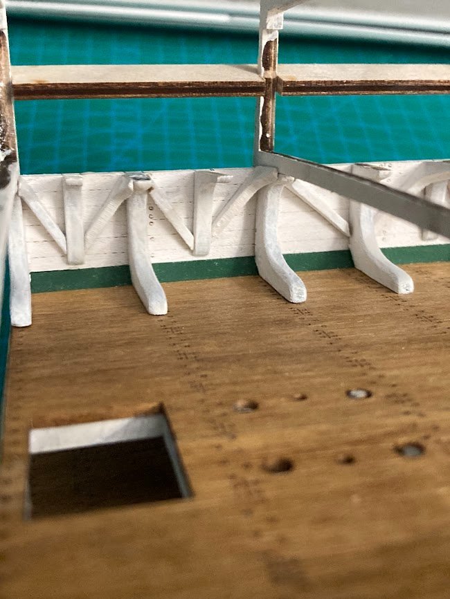
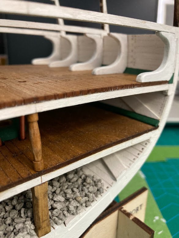
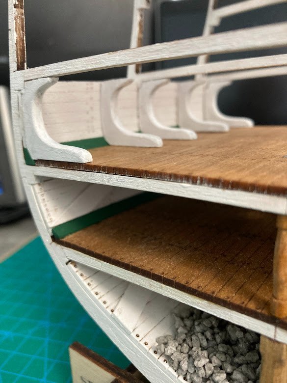
Berthing Deck Continued Hanging and diagonal knees glued in place (Port side view). Next step is the Gun deck frames followed by carving and fitting the Berthing Deck stanchions.
- 18 replies
-
- 3
-
-
- Constitution
- Model Shipways
- (and 1 more)
-
Tomculb reacted to a post in a topic:
USS CONSTITUTION by Old Navy – Model Shipways Kit No MS2045 - 1:76.8 - Cross-Section
-
ccoyle reacted to a post in a topic:
USS CONSTITUTION by Old Navy – Model Shipways Kit No MS2045 - 1:76.8 - Cross-Section
-
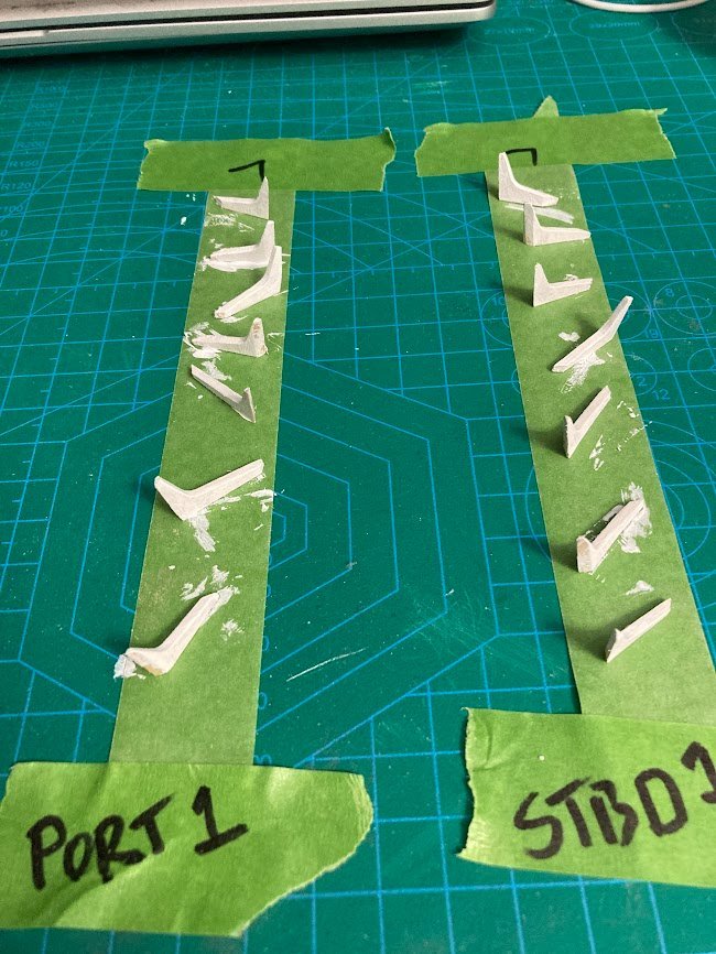
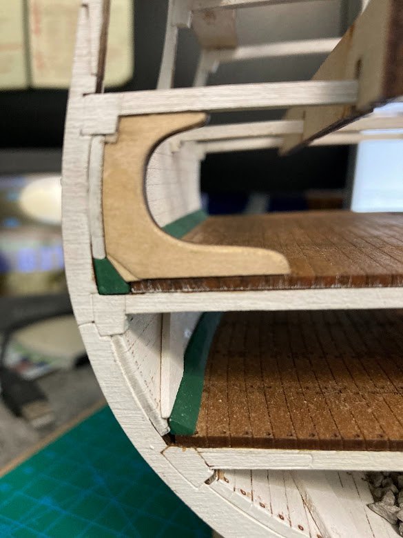
Berthing Deck continued Hanging knees installed. They are by far the easiest to install. Diagonal knees dry fitted, indexed, and painted. Final install to follow.
- 18 replies
-
- 2
-
-
- Constitution
- Model Shipways
- (and 1 more)
-
Tomculb reacted to a post in a topic:
USS CONSTITUTION by Old Navy – Model Shipways Kit No MS2045 - 1:76.8 - Cross-Section
-
Tomculb reacted to a post in a topic:
USS CONSTITUTION by Old Navy – Model Shipways Kit No MS2045 - 1:76.8 - Cross-Section
-
Tomculb reacted to a post in a topic:
USS CONSTITUTION by Old Navy – Model Shipways Kit No MS2045 - 1:76.8 - Cross-Section
-
Ziggy, I'm enjoying the build, the history, and the detailed but sometimes confusing build/rebuild details of the Constitution. Way back in 1992 when serving as Chief Engineer on the USS BOWEN FF 1079 the ship was moored bow to bow with Constitution during a Boston port visit. I had the Command Duty Officer the first day in and had to coordinate evening and morning colors. Constitution duty officer informed me that they fire 2 forward facing cannons as part of evening colors. Normally I would preside over colors on the fantail to observe raising/lowering the Ensign but given the bow to bow configuration and the cannon firing I observed colors on the bow for the lowering of the Jack. I did not inform the color guard of the cannon firing. 2 young sailors dressed in their summer whites, standing at attention, lots of spectators on the pier, awaiting the typical music to commence and suddenly 2 cannons are fired 50 feet in front of them. I thought it was pretty humorous but you can imagine the 2 young sailors were not happy and I'm at least one of them had to do a skivvy check. In 1998-99 while assigned to the US Naval Academy I led Midship summer cruise training on the yard patrol craft and we moored at the Coast Guard station across from Constitution. This time I informed the duty officers and color guards that Constitution fired her cannons.
- 18 replies
-
- 1
-
-
- Constitution
- Model Shipways
- (and 1 more)
-
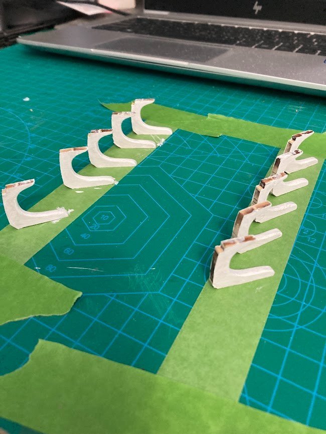
Berthing Deck - Standard Knees installed Reversed masking tape helps with paint drying and keeping the knees in order Standard knees glued in place Port and Stbd. I really need a better focusing camera. Sorry for the blur.
- 18 replies
-
- 3
-
-
- Constitution
- Model Shipways
- (and 1 more)
-
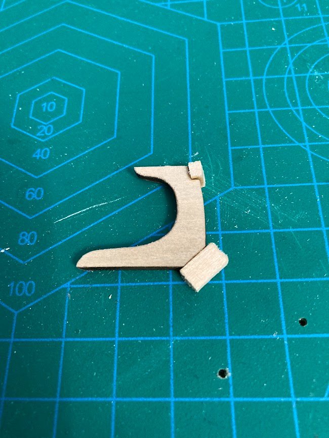
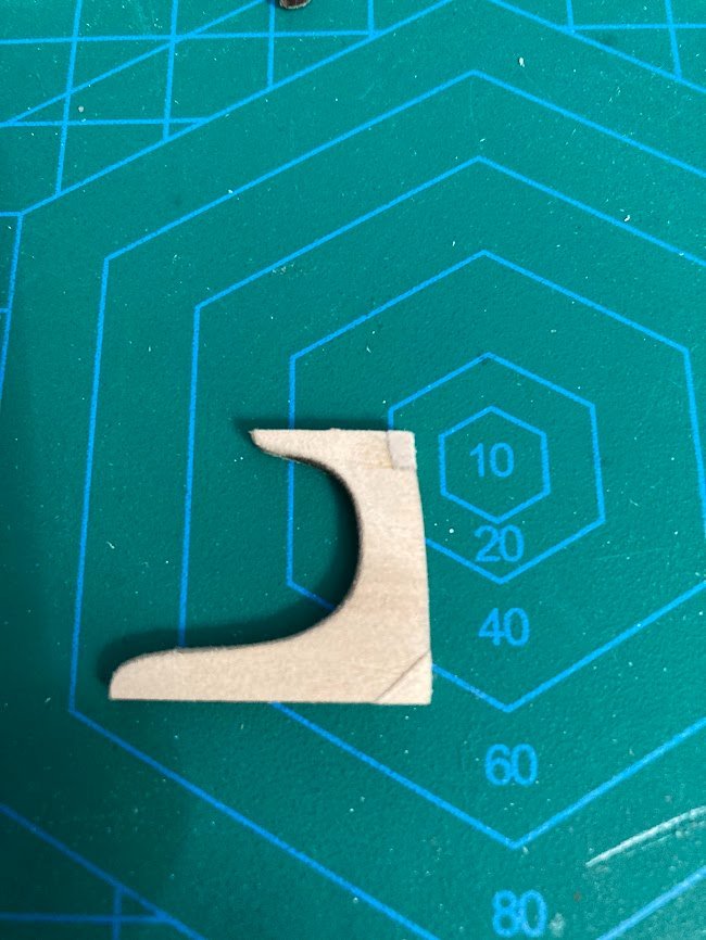
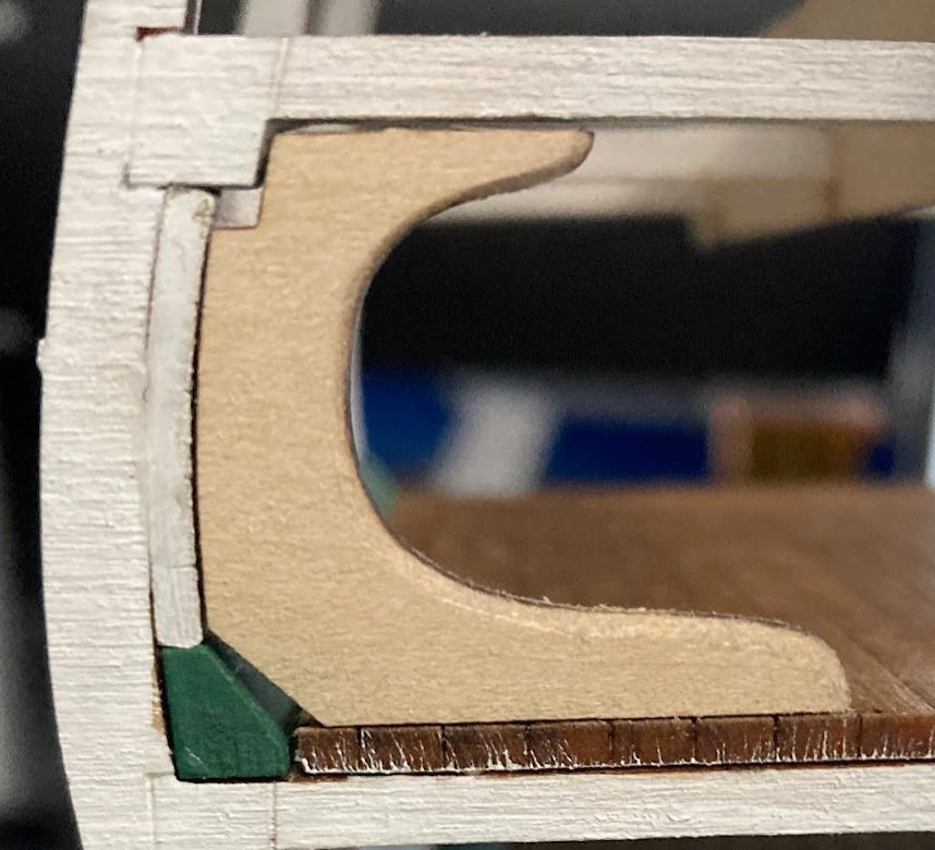
Berthing deck knees Adding filler material to knees. First modified knee dry fitted. Very time consuming but worth the effort in the long run. Knees will be painted prior to final install.
- 18 replies
-
- 3
-
-
- Constitution
- Model Shipways
- (and 1 more)
-
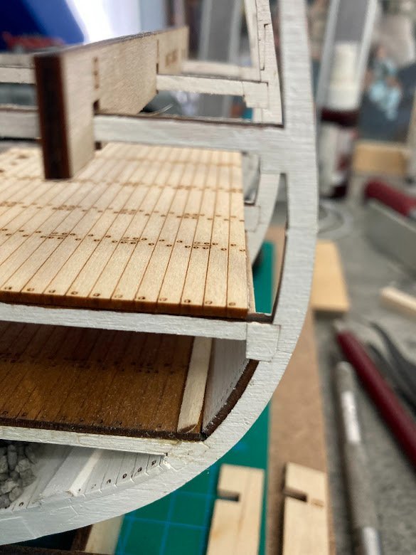
Berthing Deck Continued Berthing deck glued in place and the 6 suctions pipes fitted flush to the berthing deck. Next step is to install the knees. As mentioned in previous builds the knee notches do not come close to fitting the waterway or the gun deck beam. I'll have to add filler material to both areas, trim to fit, paint, and then glue in place. Note- all other deck fittings will be installed after all the knees are in place.
- 18 replies
-
- 3
-
-
- Constitution
- Model Shipways
- (and 1 more)
-
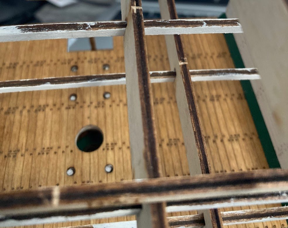
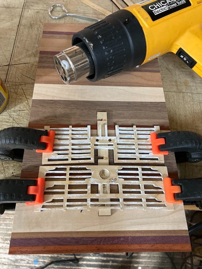
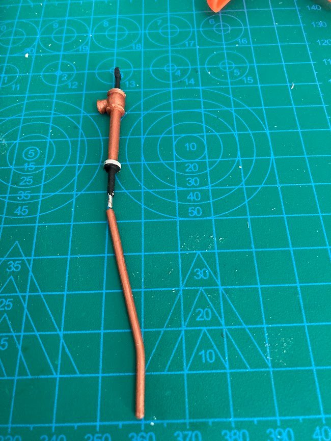
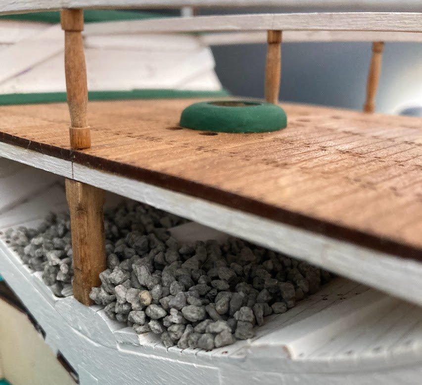
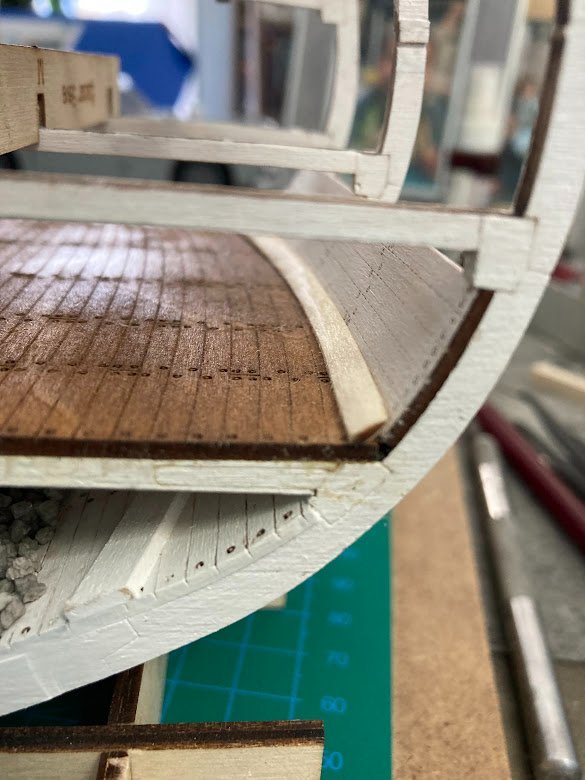
Berthing Deck Berthing deck starts with the waterways followed by the deck framing. The deck framing needs about 1/8 inch of centerline camber and this was easily accomplished, per instructions, by clamping the frames over 1/8 scape and applying heat for a few minutes. Deck frames fitted and aligned with mast. Prior to installing the berthing deck planks I have jumped ahead and been working on the 6 pumps (on the gun deck) and the suction pipes (berthing deck to hold). Not sure why the kit has the large s bend in the suction pipes. Although details are limited, the suction pipes appear in all drawings/plans to be straight and angled between the berthing deck and the orlop deck and then need a slight bend to vertical in the hold. Still working the berthing deck details to include the pump base, hatch, ladders, stanchions, side walls and knees.
- 18 replies
-
- 2
-
-
- Constitution
- Model Shipways
- (and 1 more)
-
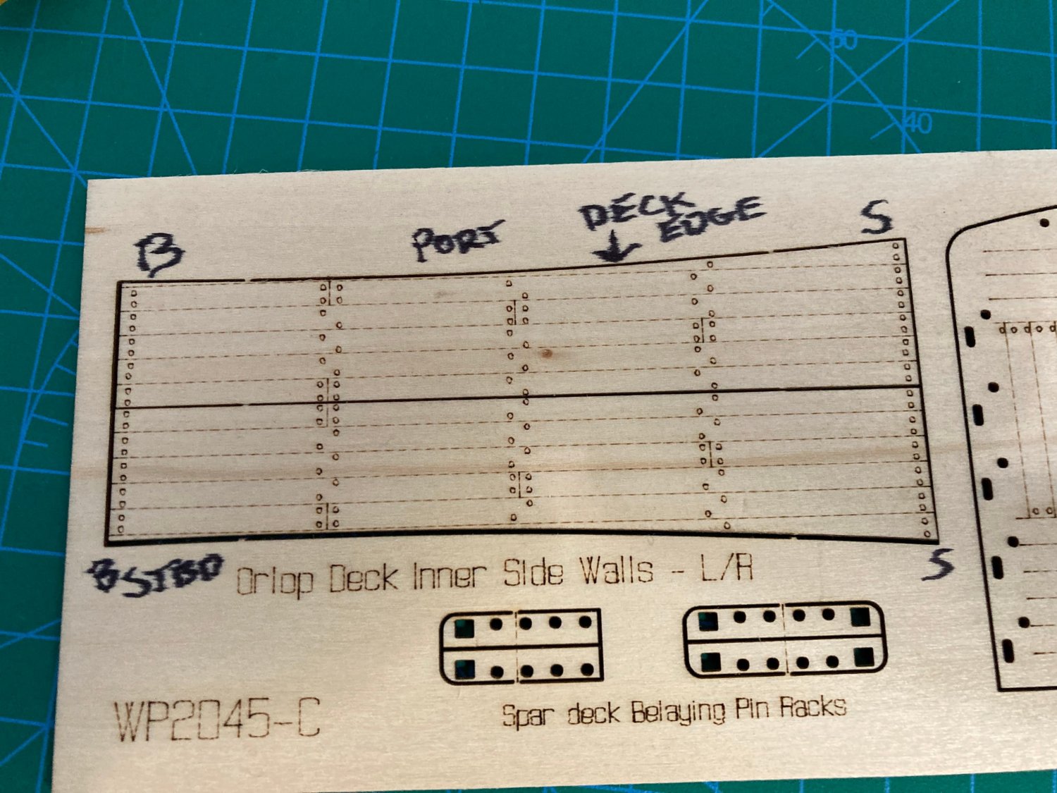
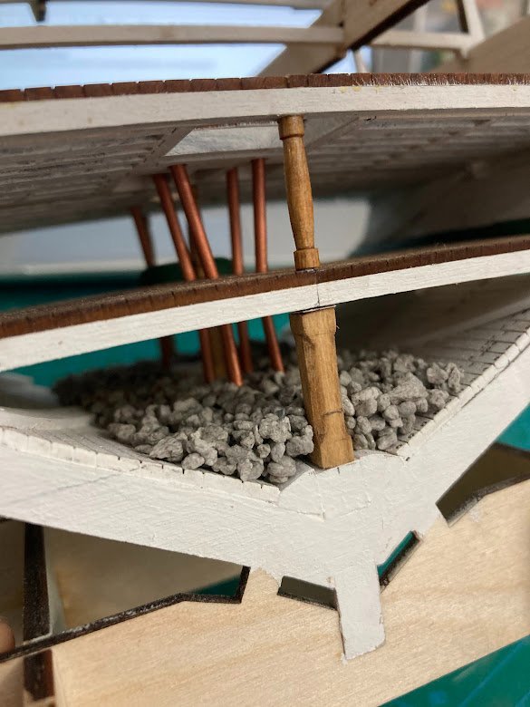
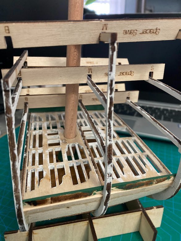
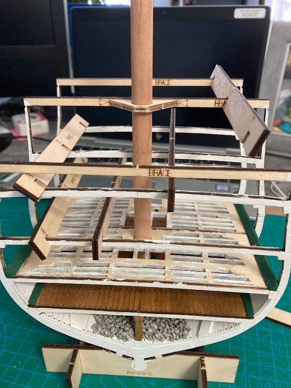
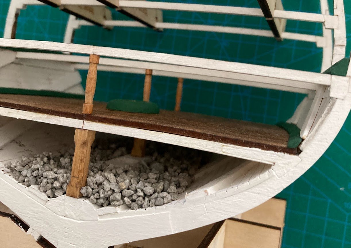
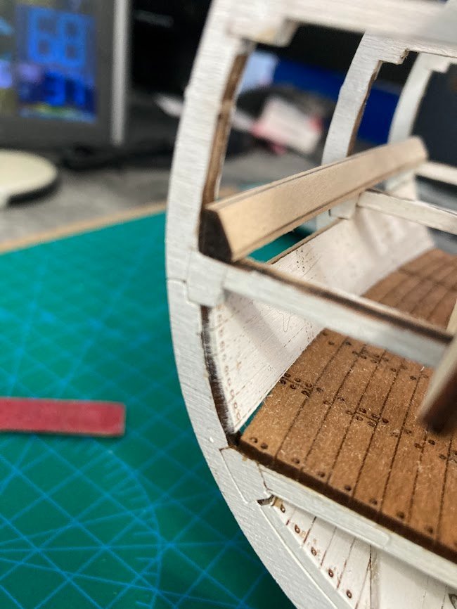
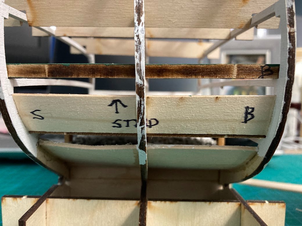
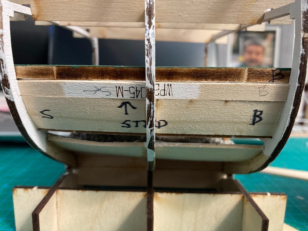
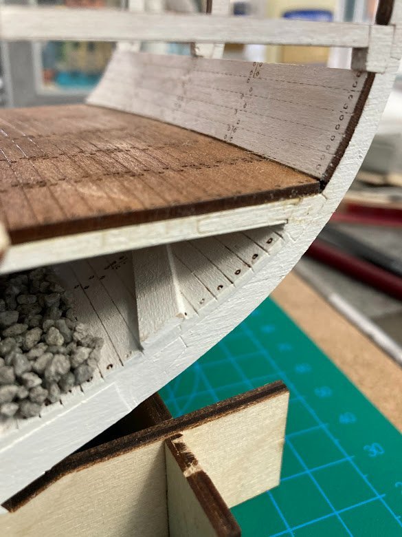
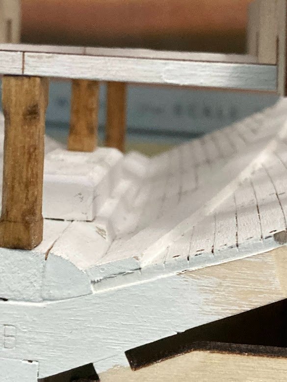
Orlop Deck, Diagonal Braces and Stanchions Braces and stanchions need to be installed prior to the Berthing Deck frames and deck are installed. The kit instructions have you fitting and installing the diagonal braces after the berthing deck is installed. Makes no sense and greatly increases fitting and installation. I used a strip of 1/4 inch wide paper to make a template to get the angles correct. As Tom pointed out in his build the instructions never indicate to add 3 stanchions on the Orlop deck but clearly show in pictures as well as the kit drawings. The 1927-1931 restoration plans as well as Marquardt drawings show that the stanchions are the 9 x 9 inch square post as are the stanchions in the hold. Additionally for the cross section there should be 5 stanchions vice 3. I had already made the 3 round stanchions so I installed them per the kit drawings. Whichever style/number you choose, install them prior to the Berthing Deck frames.
- 18 replies
-
- 3
-
-
- Constitution
- Model Shipways
- (and 1 more)
-
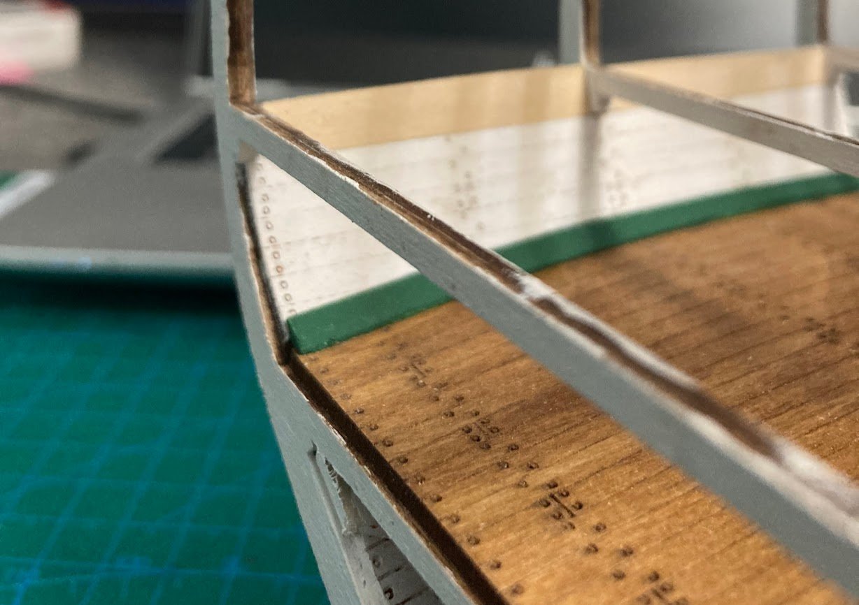
Orlop Deck, side walls, and stringers (waterways) continued. It is clearly apparent that there is a gap between the top of the Orlop sidewall and the bottom of the Berthing Deck stringer. The instructions state to fit a 1/4 x 1/4 filler. The gap is wider than a 1/4 inch and can be filled with scrap from the ORLOP deck sheet. This is easily accomplished prior to gluing the Berthing deck stringer. Fillers installed. Also the Orlop deck stringer is installed.
- 18 replies
-
- 2
-
-
- Constitution
- Model Shipways
- (and 1 more)
-
Tom, Can't thank you enough for your highly detailed build log and pointing out the challenges and pitfalls. Todd
-
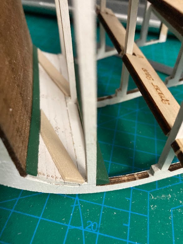
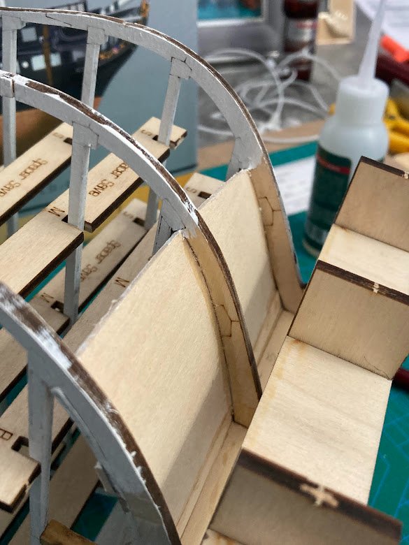
Orlop deck and lower mast fixture Prior to installing the Orlop deck the lower mast fixture will need to be made to include the taper and the 45 deg chamfer. When making the mast step I used a counter sink bit to create the 45 deg chamfer in the 1/4 inch hole. For the mast fixture I created a matched 45 using a bench top sanding disk and miter gauge set. Out of practicality I saw no reason to add the 1/4 inch locating pin at a 3.5 degree offset. The matching 45s provided the perfect alignment and allowed the fixture and the main mast to be rotated to account for any non linear characteristic of the wooden dowel. Orlop Deck, side walls, and stringers (waterways). This is the first major challenge with the build due to part fitment, misleading instructions, and historical accuracy. The instructions show the build procedure for the Berthing, Gun, and Spar deck wherein the stringer is shaped and installed first, followed by the deck and then side wall. The kit drawings show the sidewall installed deck beam to overhead beam and then the deck between the side walls and the stringer is fitted on top. The instructions state to shape the stringer as if it is to be installed first and the deck and sidewalls to be fitted after. The instructions and the part fitment then go on to state to install the deck first, followed by the side walls and then add the the stringer. The deck and the side walls fit nearly perfectly but the stinger required major modification to retain any semblance to scale. Deck and side wall alignment. Note that the deck is fitted first followed by the sidewall as per instructions. The upper decks and stringers are very different in that the deck is narrower to allow for the stringer to be fitted first. First attempt on modifying and fitting (dry) the stringer. Not sure I'm satisfied with the result.

- 18 replies
-
- 1
-
-
- Constitution
- Model Shipways
- (and 1 more)
-
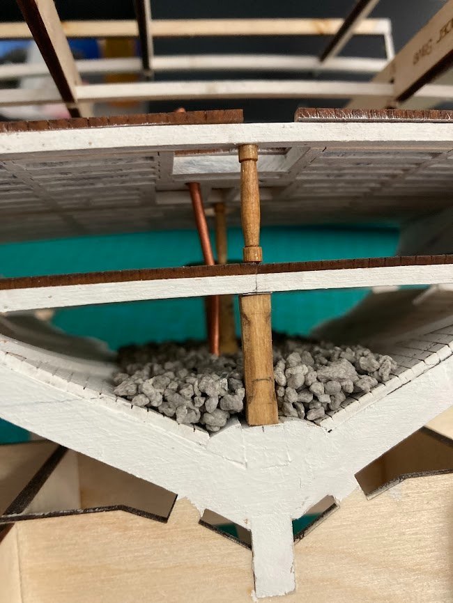
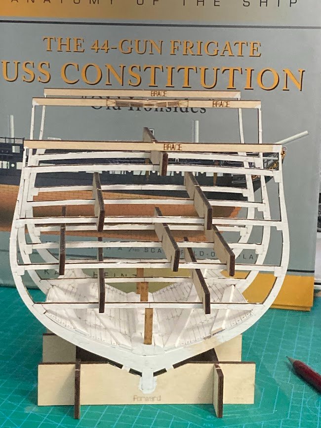
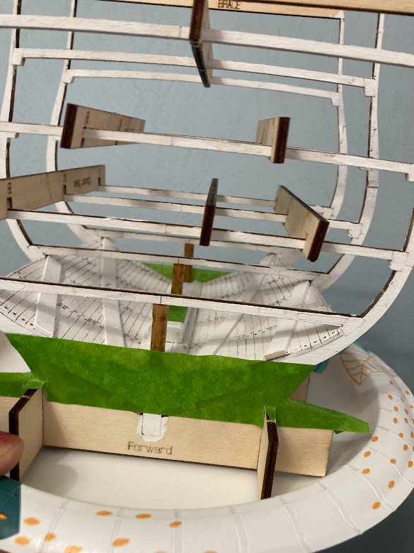
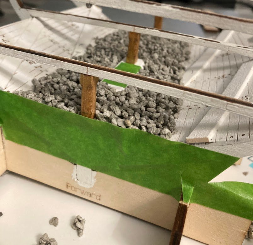
About 2 months ago I got the itch to continue my nearly fifty years of model boat/ship building by adding a cross section model of the USS CONSTITUTION to my fleet. A few Google searches pointed me to this site and the build logs by TomCulb and UnixGuy. After reading through their build threads as well as Model Shipways online instructions I ordered the kit from Amazon. I'm really looking forward to the detailed standing and running rigging. Fortunately my kit had no missing parts. I made sure the brass etched gun port hinges were included. On to the build. I'll offer up some tips and minor alterations. I have quickly come across the challenge of the differing years documentation as well as a few errors in the kit instructions. Overall the quality of the sheet goods and laser cutting is excellent. Basic frames, Keel, Mast Step, and hold walls. The hold walls installed without the need to wet or use heat. Nice tight joints. Mast Step and Limbers per instructions Ready for gravel ballast Based on the top of the mast step I extended lines out to the forward and aft frames to establish level lines for the tape. This helped to a=ensure the gravel bed was level and not under or over filled. Based TomCulbs report of dripping glue I did place the model on a paper plate and I also drained excess water on paper towel prior to placing in the hold. Very pleased with results - level bed and not a single loose pebble when inverted. I will not install the barrels until the outer planking is complete. This will also allow good visibility when installing the pump suction pipes into the hold.
.jpg.e79f1cb9841e44f14d50aa2d85d943a1.jpg)
.jpg.44365f5956bda8ffea3e1cc51e945ca3.jpg)
- 18 replies
-
- 4
-
-
- Constitution
- Model Shipways
- (and 1 more)
-
uploading pictures
Old Navy replied to David56's topic in How to use the MSW forum - **NO MODELING CONTENT**
Image Test.jpg.1370839a02b27f22a4166237b013cf83.jpg)
-
uploading pictures
Old Navy replied to David56's topic in How to use the MSW forum - **NO MODELING CONTENT**
Image test
-
I came across the amazing website and highly informative forum during my research on the Model Shipway USS Constitution cross section. I read through Tom Culb's build thread at least 4 times and ordered the kit and the build has commenced. Retired Navy Officer and currently working as a contractor supporting Department of the Navy in Norfolk, VA. Fascinated with boats/ships and the sea. I started building ship models at the age of 9 (Mayflower) and have been building ever since. Some of my models include: Scratch built Charles W Morgan (hull only @ age 10) AL Blue Nose II Revell USS Constitution Scratch built Steam launch with fully operating steam plant The following Dumas RC Models: Star 45 Sail boat American Enterprise 5 Mahogany runabouts Maine Lobster boat Myrtle Cory Stern wheeler Mount Washington side wheeler Todd