Javelin
-
Posts
287 -
Joined
-
Last visited
1 Follower

Recent Profile Visitors
729 profile views


.thumb.JPG.4d3261ccae06041fa7cc2933fb43d577.JPG)

-
 yvesvidal reacted to a post in a topic:
TI Europe by Javelin - 1/700 - PLASTIC
yvesvidal reacted to a post in a topic:
TI Europe by Javelin - 1/700 - PLASTIC
-
Glen McGuire reacted to a post in a topic:
TI Europe by Javelin - 1/700 - PLASTIC
-
Rudolf reacted to a post in a topic:
Soleil Royal by Hubac's Historian - Heller - An Extensive Modification and Partial Scratch-Build
-
Keith Black reacted to a post in a topic:
TI Europe by Javelin - 1/700 - PLASTIC
-
jerome reacted to a post in a topic:
TI Europe by Javelin - 1/700 - PLASTIC
-
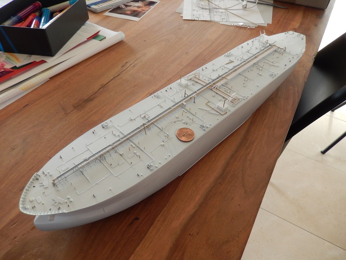
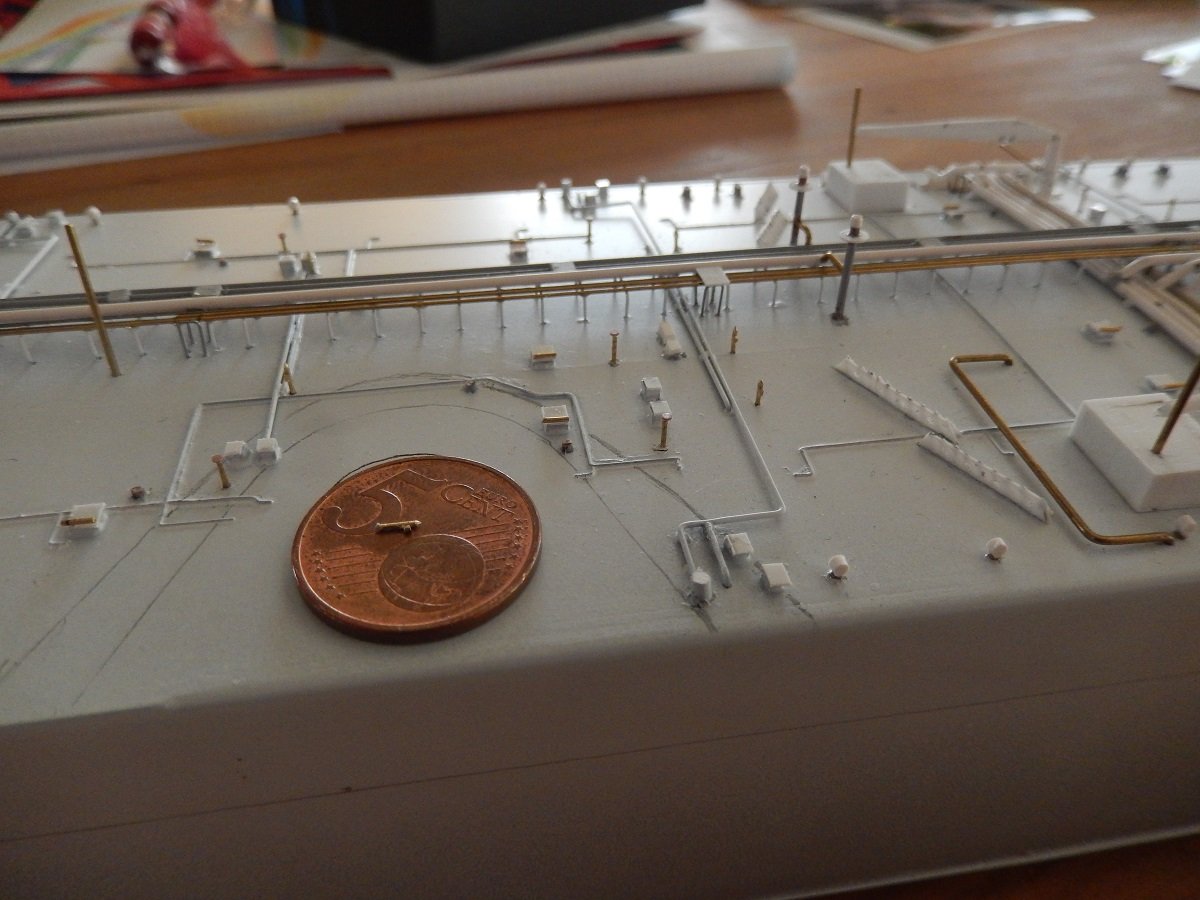
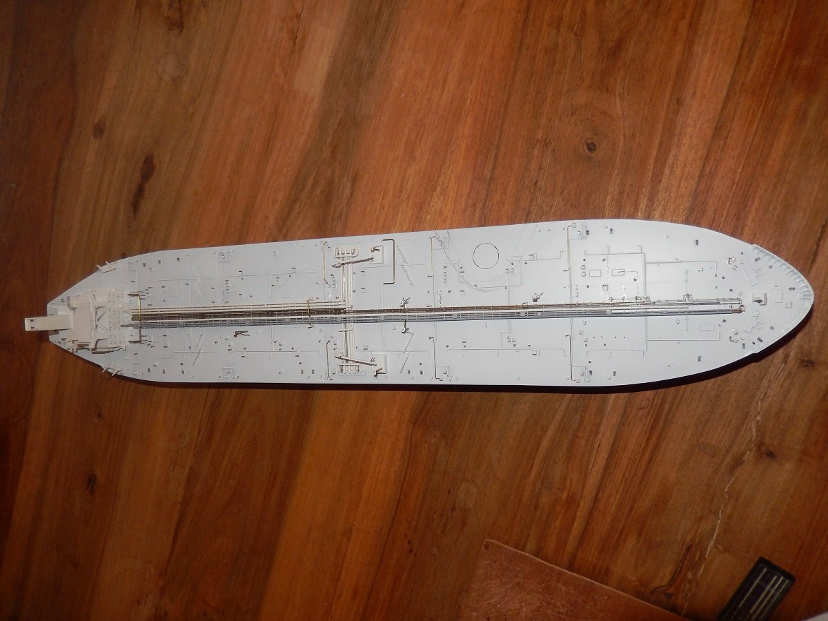
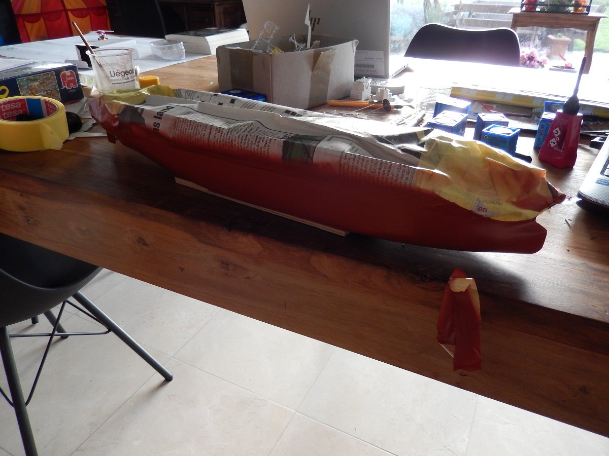
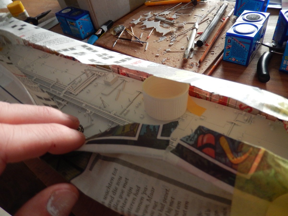
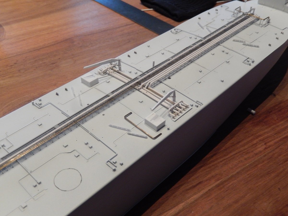
 For sure it would be a long tour... It effectively takes over 5 minutes to get from the bow to the accommodation. Really annoying when you had a job near the bow and you forgot a tool! Then it was time for the finer detailing. Each tank has some P/V (Pressure/Vacuum) valves that stand on deck. They release gas when there is an overpressure and suck in air when there is a vacuum, although that vacuum is normally prevented by topping up with Inert Gas. They are only safeties. I built the overpressure part from a brass wire with a sharpened point, while the vacuum part is just a small cylindrical parts stuck to that wire. A whole forest of these things all around the vessel. Although there are only 3 cargo pumps, that doesn't mean there are only 3 cargo tanks. There are large center tanks, with on each side smaller wing tanks. And each one of those cargo tanks has its own P/V valve of course. And an overview of the nearly completed deck. Mainly the mooring winches and fairleads are still missing. And then it was time to get that bottom painted. Sprayed it with a spray can, easier with this size of vessel. Masking is of course tricky over all the details. To avoid any damage and to be able to turn the vessel around for spraying, I stuck some high bottle caps to the deck, where space was available. They were stuck there with some masking tape before I applied the mask of newspapers and masking tape. You have to make sure of course that the caps are higher than the highest details 🤪
-
Javelin reacted to a post in a topic:
USS Constitution by mtbediz - 1:76
-
Javelin reacted to a post in a topic:
USS Constitution by mtbediz - 1:76
-
 Javelin reacted to a post in a topic:
Perseverance 1807 by Isaiah - FINISHED - Modellers Shipyard - Colonial Brig
Javelin reacted to a post in a topic:
Perseverance 1807 by Isaiah - FINISHED - Modellers Shipyard - Colonial Brig
-
yvesvidal reacted to a post in a topic:
TI Europe by Javelin - 1/700 - PLASTIC
-
GrandpaPhil reacted to a post in a topic:
TI Europe by Javelin - 1/700 - PLASTIC
-
GrandpaPhil reacted to a post in a topic:
TI Europe by Javelin - 1/700 - PLASTIC
-
Keith Black reacted to a post in a topic:
TI Europe by Javelin - 1/700 - PLASTIC
-
mtaylor reacted to a post in a topic:
The Mayflower by Knocklouder - Amati - 1:60
-
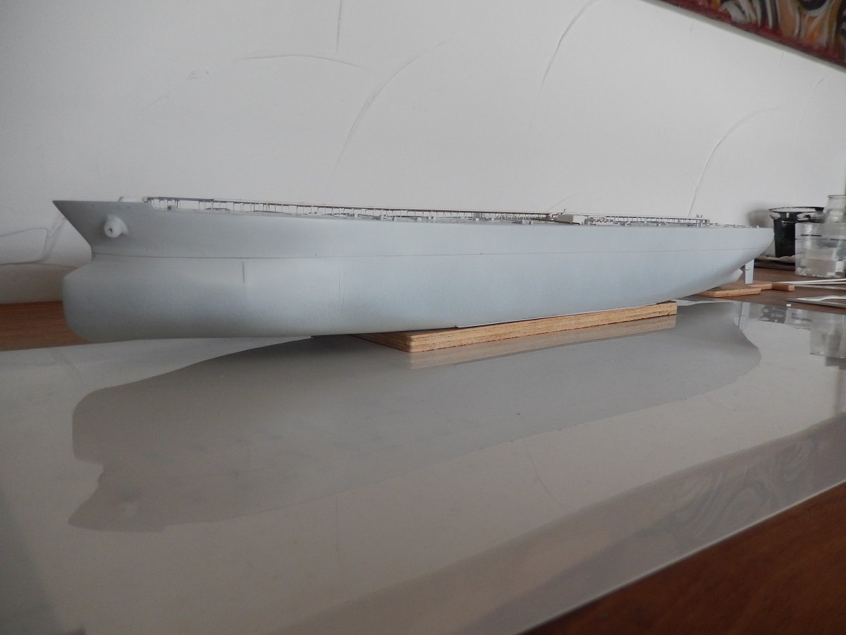
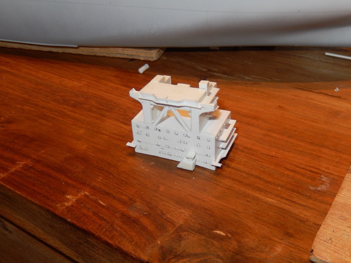
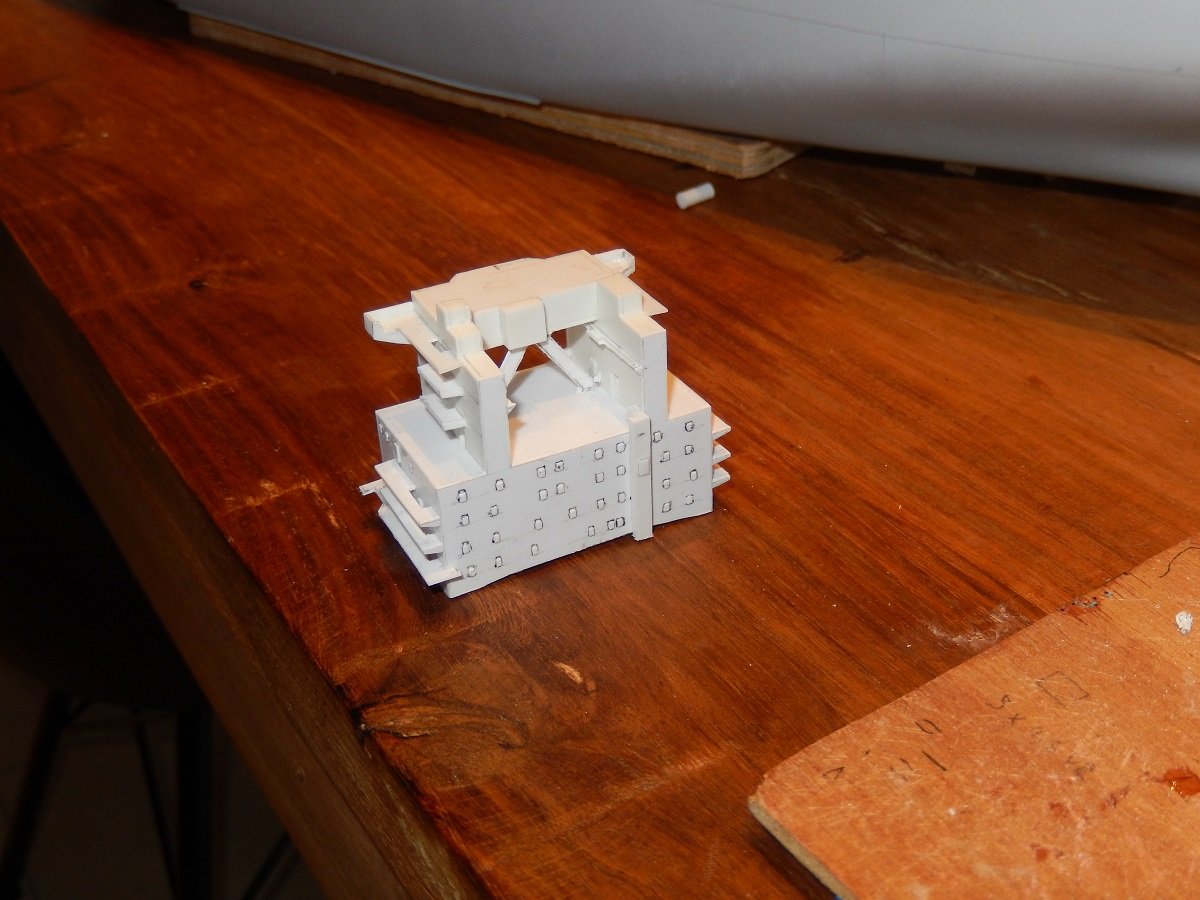
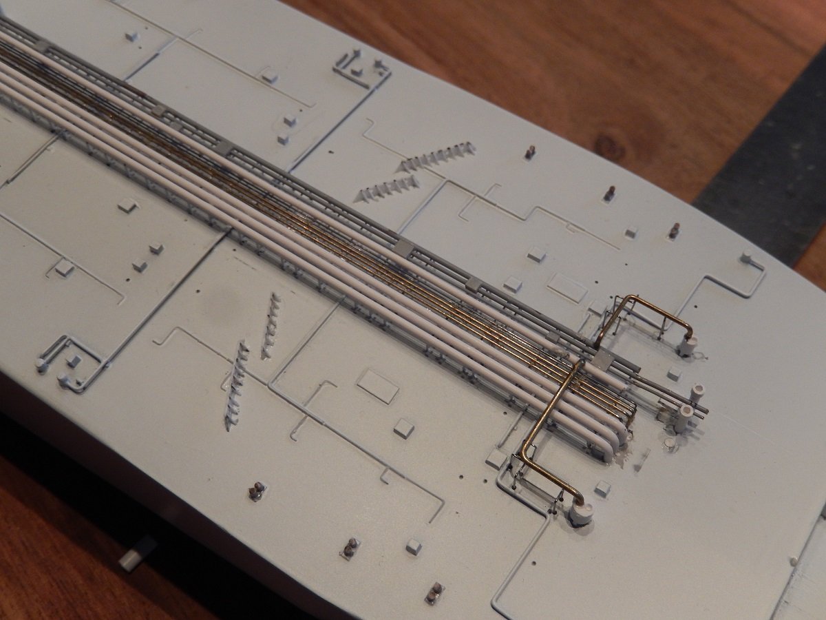
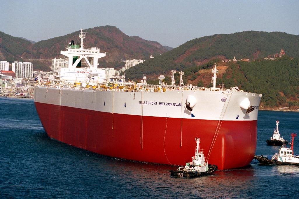
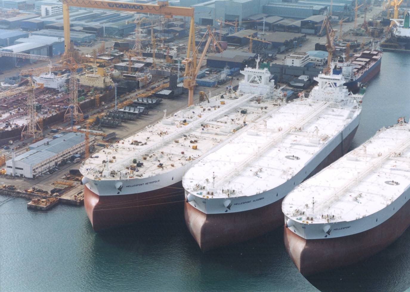
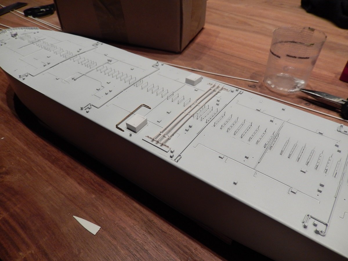
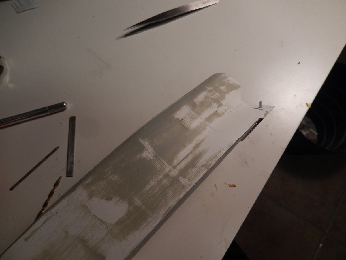
Thanks Keith, Thought I didn't have so many pictures of this build, but it seems I was wrong. In any case. Next were the prominent oil cargo piping going from the pumproom (where three pretty potent cargo pumps are located) to the manifold area. Furthermore there is also the line with all the small boxes, which in fact is just a duct for electrical cables, with the boxes being junction boxes in between. And then the last layer of piping is a few connection pipes at the aft end where the Inert Gas (in this case produced from engine exhaust gas) is sent from the engine room to the cargo tanks. These inert gas lines are also connected through a water seal that will overflow in case of overpressure in the inert gas line or the water will be sucked into the line to eventually let air in and prevent vacuum. These seals are located in front of the accommodation between the engine room pipe and the deck pipe. You also see the aft set of wavebreakers and some bollards on deck. Slowly going up, so next were the cargo hose handling cranes And some vent masts that allow to vent cargo vapours and/or inert gas to a safe place without endangering anybody on deck. The accommodation block itself has a surprising amount of detail that even I wasn't aware of... Luckily I had some pictures as well as a lot of pictures I found online, to get the puzzle together. And time to mark the waterline on the hull as well. I always paint my hull fully with the lightest colour (be it the hull colour or the anti-fouling colour), so that I don't have any gaps when painting the other part. You can see some dark vertical lines near the bow. Those are actually cracks. I don't have those on my smaller builds, so I'm assuming it is caused by the method of construction together with the large size of the ship. I had it on one other, large, build with a similar construction method as well. These cracks also don't appear directly, they usually only show after a few weeks. I'm assuming it is due to the expansion/contraction of the styrene skeleton vs the more rigid filler. In the end I do always succeed to fill those cracks/paint them over. And the massive bulk of the real ones. And yes, there are cars near the building on the left to compare...
-
Javelin reacted to a post in a topic:
HM Gun Brig Adder 1797 by DB789 - Vanguard Models - 1:64
-
Javelin reacted to a post in a topic:
HM Gun Brig Adder 1797 by DB789 - Vanguard Models - 1:64
-
Javelin reacted to a post in a topic:
HM Gun Brig Adder 1797 by DB789 - Vanguard Models - 1:64
-
 Javelin reacted to a post in a topic:
TI Europe by Javelin - 1/700 - PLASTIC
Javelin reacted to a post in a topic:
TI Europe by Javelin - 1/700 - PLASTIC
-
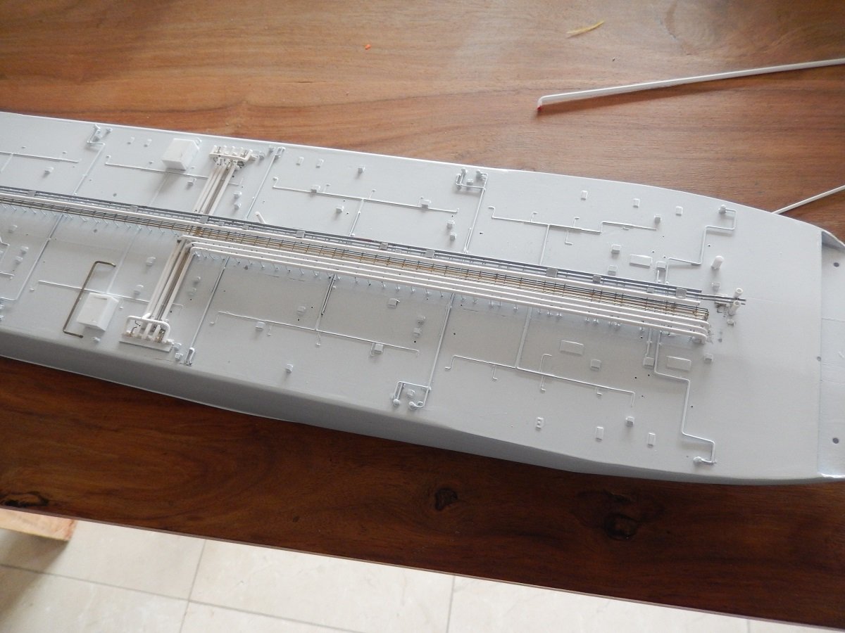
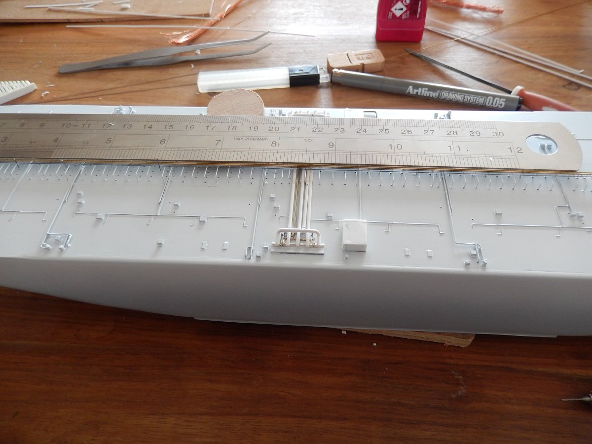
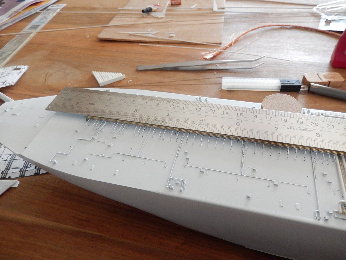
All of the above was in preparation for the first coats of paint. If I'd continue with the next layers up, they would likely cause shadow areas during spraying. First came a coat or 2 of grey primer. Working with white top coats makes it extremely important to remove any contrasts below the paint. Pencil marks are notably difficult to get covered with white. I therefore first use grey primer to even out all contrasts, later on followed by white top coat. Regarding the piping supports: - I drilled holes through the deck to allow for height adjustment - I made the brackets using jigs to have them all equally sized and shaped - I then inserted the first bracket, using a styrene piece inside the inverted U to determine the correct height - I then used that same piece of styrene (a long bar shape) to place the second one - Slowly going forward using that same piece of styrene, each time blocked under 2 fixed supports while mounting the next 2 supports - while doing this, I used a metal ruler to push the brackets each time down, creating a long straight line on top of the brackets in a longitudinal direction After this initial coat came the second layer of piping, pipes that aren't quite on deck, but just slightly above (taking into account the 1/700 scale of course) And then came the typical long longitudinal pipes. Again I used the metal ruler to keep things straight. Over such long lengths, 0.3mm and 0.5mm wires have a tendency to bend. While moving to each next pipe, I used small spacers with a diameter depending on the actual spaces. In the above and below picture you can make out some 0.3mm wire in vertical position between the last longitudinal wire and the one-but-last one. These spacers were of course removed afterwards.
-
Javelin reacted to a post in a topic:
Hannah by gjdale (Grant) - FINISHED - Amati - 1:300 - BOTTLE
-
Agreed with the others on that penguin, all by itself it also immediately defines on which hemispere and pole your diorama is located, even to people that don't know the background. I indeed hadn't thought about the creeping of the epoxy. I really can't think of any way to stop or prevent that. The only thing I could think of is treat the edges/waterlines of objects with vaseline or something else, not-solid. Perhaps the epoxy wouldn't get hold of it that way? Not sure if they wouldn't chemically interact though.
- 88 replies
-
- 4
-
-
- Ghost Ship
- Jenny
- (and 1 more)
-
Javelin reacted to a post in a topic:
Ghost Ship Jenny by Glen McGuire - 1/400 - BOTTLE
-
Turns out a real eye-catcher Bob. Great build and I truly love those sails. The color "scheme" of your hull is also gorgeous, love the tones of the wood mixed with the black and white, resulting in an overall balanced look. 👍
-
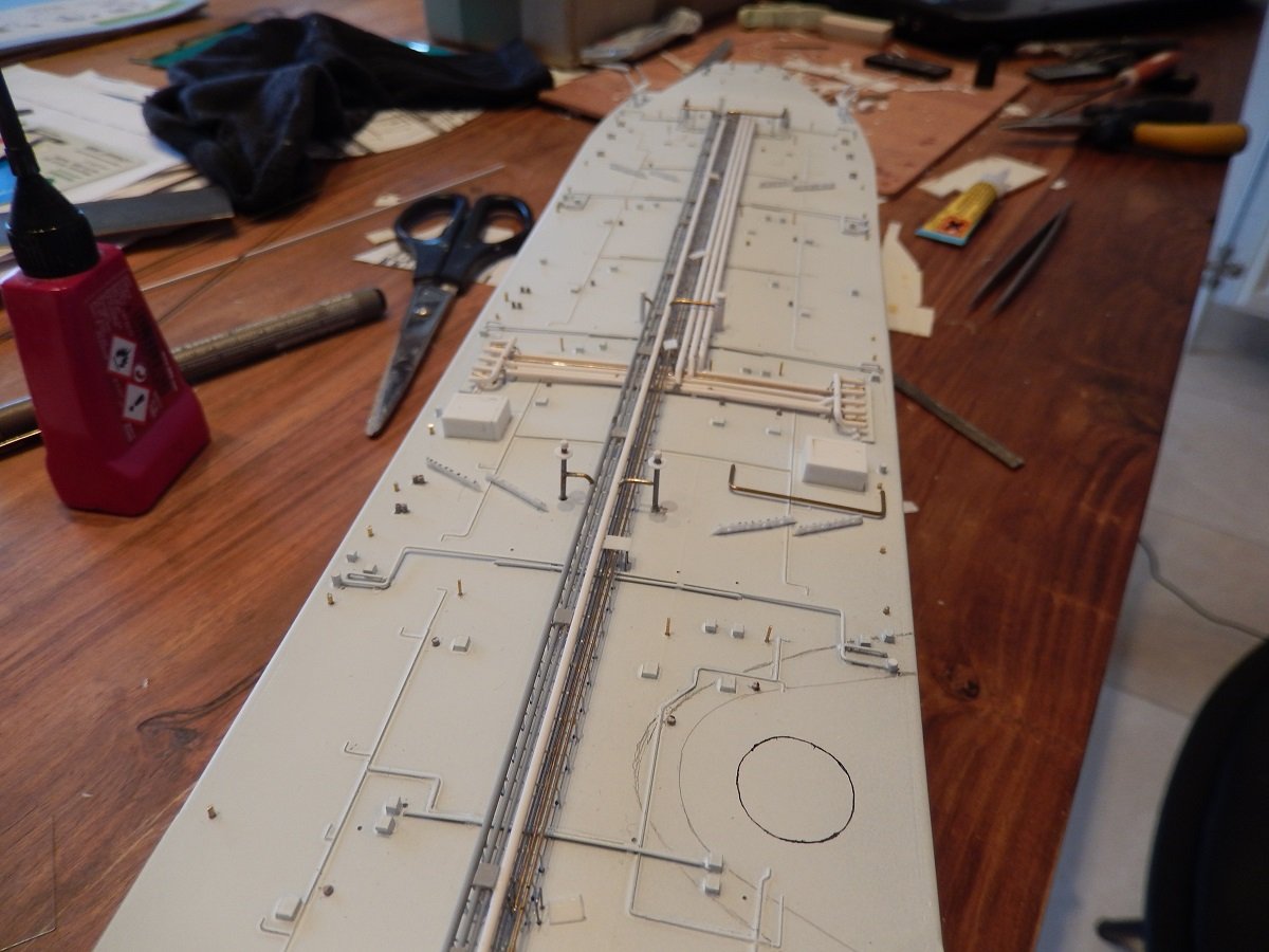
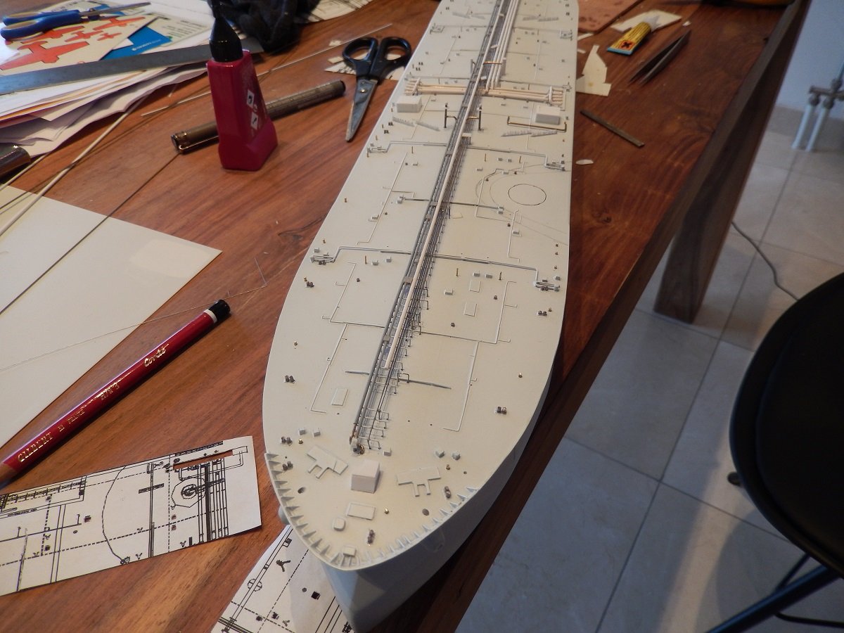
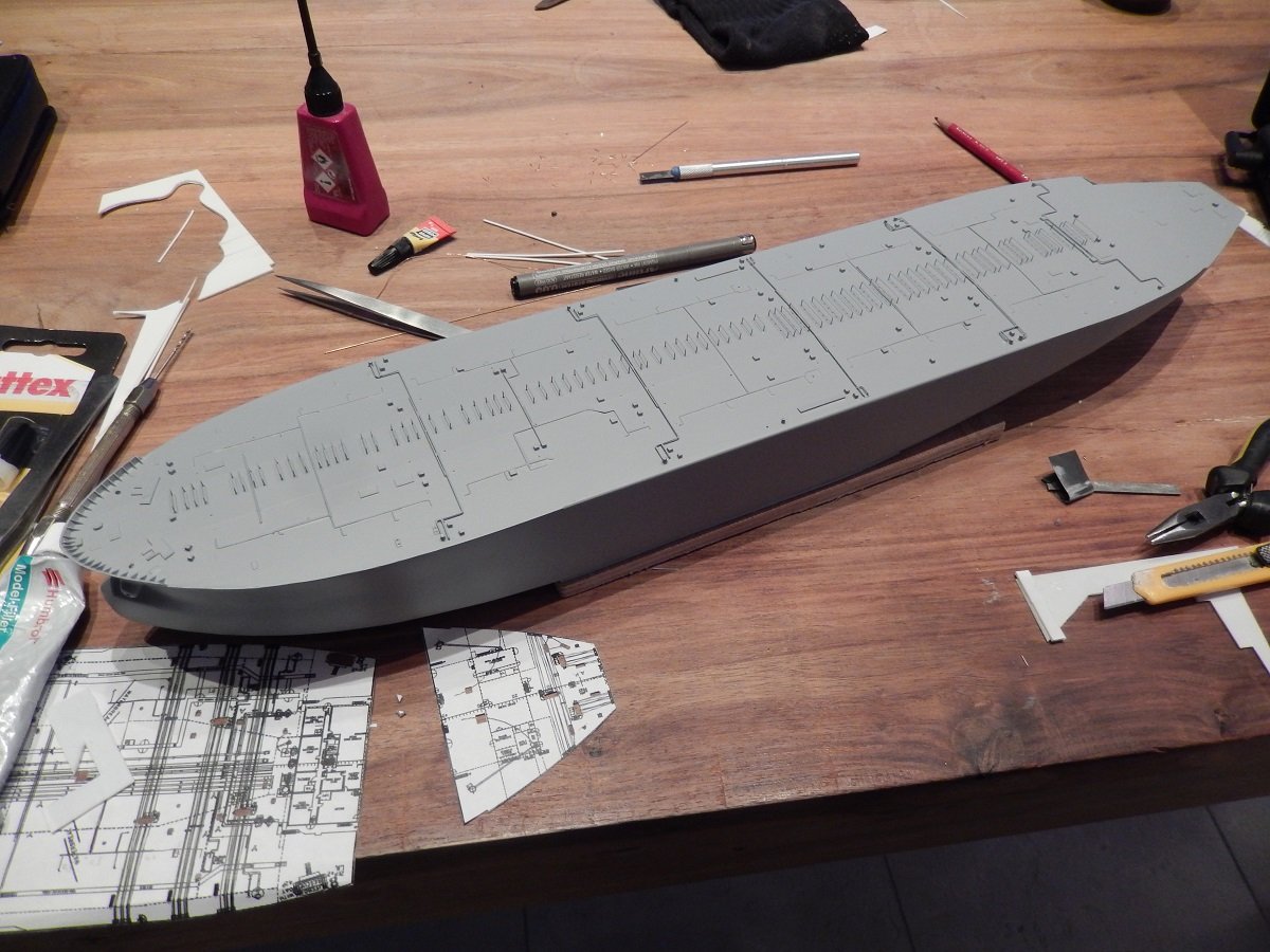
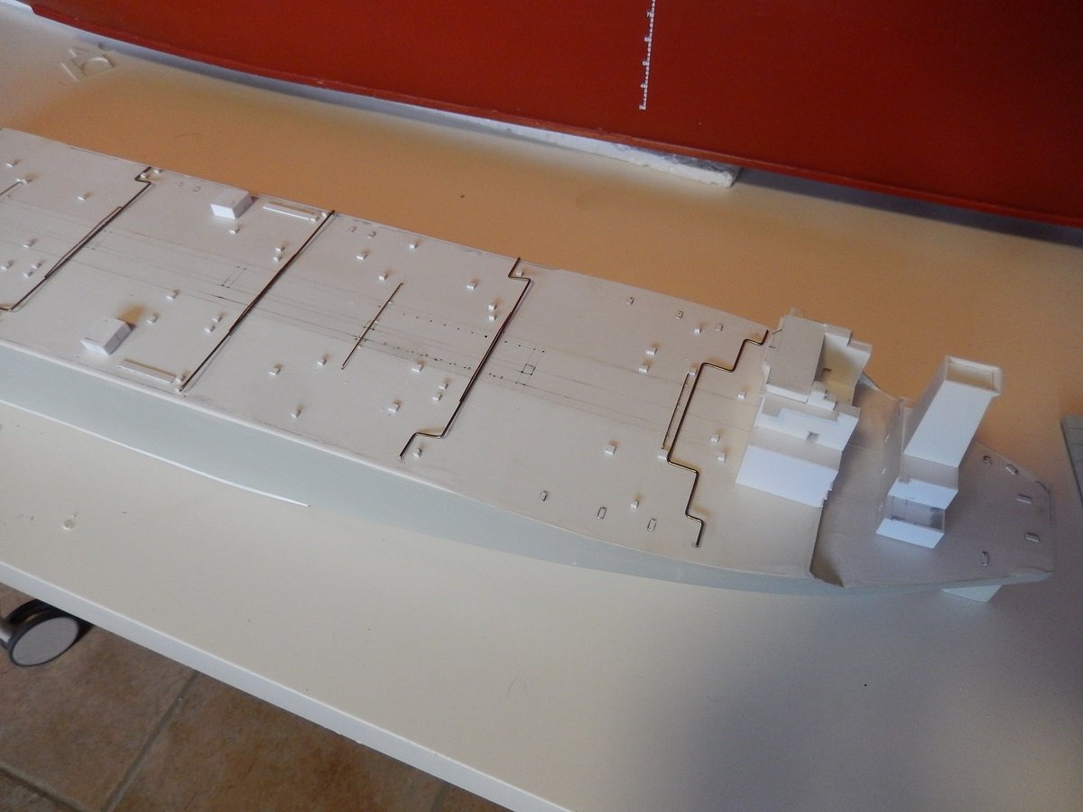
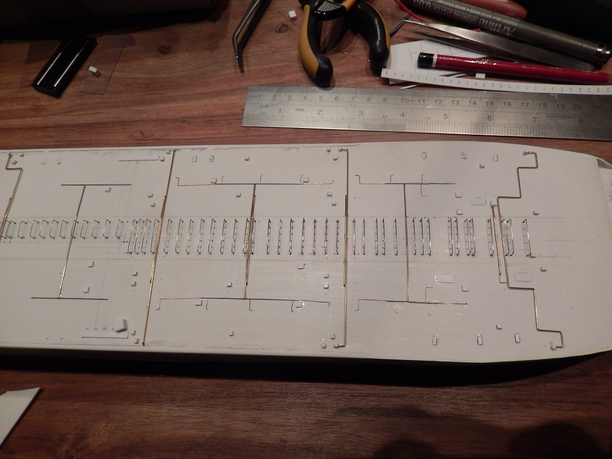
So, as crazy as it seems, this ship has little detailing to it, probably the reason why I loved building it. I love building hulls, but I sort of hate detailing (although I do torture myself by adding as much detail as possible to any build). So this subject was great for me. Oil tankers are quite simply in construction with only few different pipes on deck. First I started with some fixed points as I usually do a bottom-up approach towards detailing of tankers. These fixed points were all cargo and ballast tank entry hatches. These particular ships however had something extra. Any tanker is equipped with an inert gas plant, a plant that produces inert gas (basically exhaust gas from combustion, scrubbed with water to remove contaminants), which is used to lower the oxygen content in the cargo tanks to avoid explosions/ignitions. On gas tankers it's normally only used to prepare for dry dock or after dry dock/repairs. On oil tankers however it is continuously used to top-up/maintain cargo tank pressures. On these 4 sisters however they thought of something new. Considering the large surfaces of ballast tanks, they thought of reducing the oxygen level in the ballast tanks as well, using the inert gas plant... This meant of course that the ballast tanks also could be sealed from the atmosphere with a sort of pressure control (including vent valves to avoid over pressure). This reduction in oxygen level should then prevent corrosion and reduce the need to maintain the coating of the ballast tanks. This resulted in pipes running from the central inert gas line towards each ballast tank. These lines unfortunately made the use of bicycles (normal on such large oil tankers) very difficult, and therefore it was not done. Two deck houses were also present, which is also a very usual feature of such tankers. Close to the manifold, containing oil spill equipment as well as other things used on deck (transfer baskets etc.), since the cranes also rest on those houses. All of it was basically dry-fitted to allow me to draw out the outlines of the longitudinal piping supports. Slowly she received more pipes. In this case the Crude Oil Washing (COW) pipes, which are connected to small rotating washing machines that hang on the top of the tank. Crude Oil (=cargo) is pumped through these at certain pressures, which in turn makes the machines spin in certain cycles. The crude is then sprayed against the walls of the tank to mechanically wash off any residues of the cargo. Additionally the sprayed crude acts also as a detergent that absorbs some of that residue that is then being collected down in the tank to be pumped out. The pipes can be recognized by their transverse central pipes branching off to longitudinal pipes that connect the washing machines (spread around the tanks to fully cover the tank top/walls and bottom. The helicopter deck is also outlined in pencil. The helo deck was strengthened to take on the landing of a Sea King or similar sized helicopter. This is not too common as in most cases there is only a hover place/winching area or a helo deck for light helicopters that are used by pilots to board the vessel offshore. The central piping supports are made out of 0.3mm stainless steel wire, bent over a jig. The COW lines are a combination of 0.5mm brass, 0.3mm steel and 0.1mm copper wire. They are glued directly to the deck since this is 1/700, so the 10cm clearance between the deck and piping wouldn't really be visible.

-
But why did you put clay blobs in your bottle? I was thinking though, in real life, the largest part of an iceberg is below the surface... Do you consider adding another layer of epoxy/water to submerge part of you icebergs? Or is too late in the build to consider that? Love what you did with the ship. Difficult not to overdo the ice effects, but you clearly managed to make it work.
- 88 replies
-
- 5
-
-
-
- Ghost Ship
- Jenny
- (and 1 more)
-
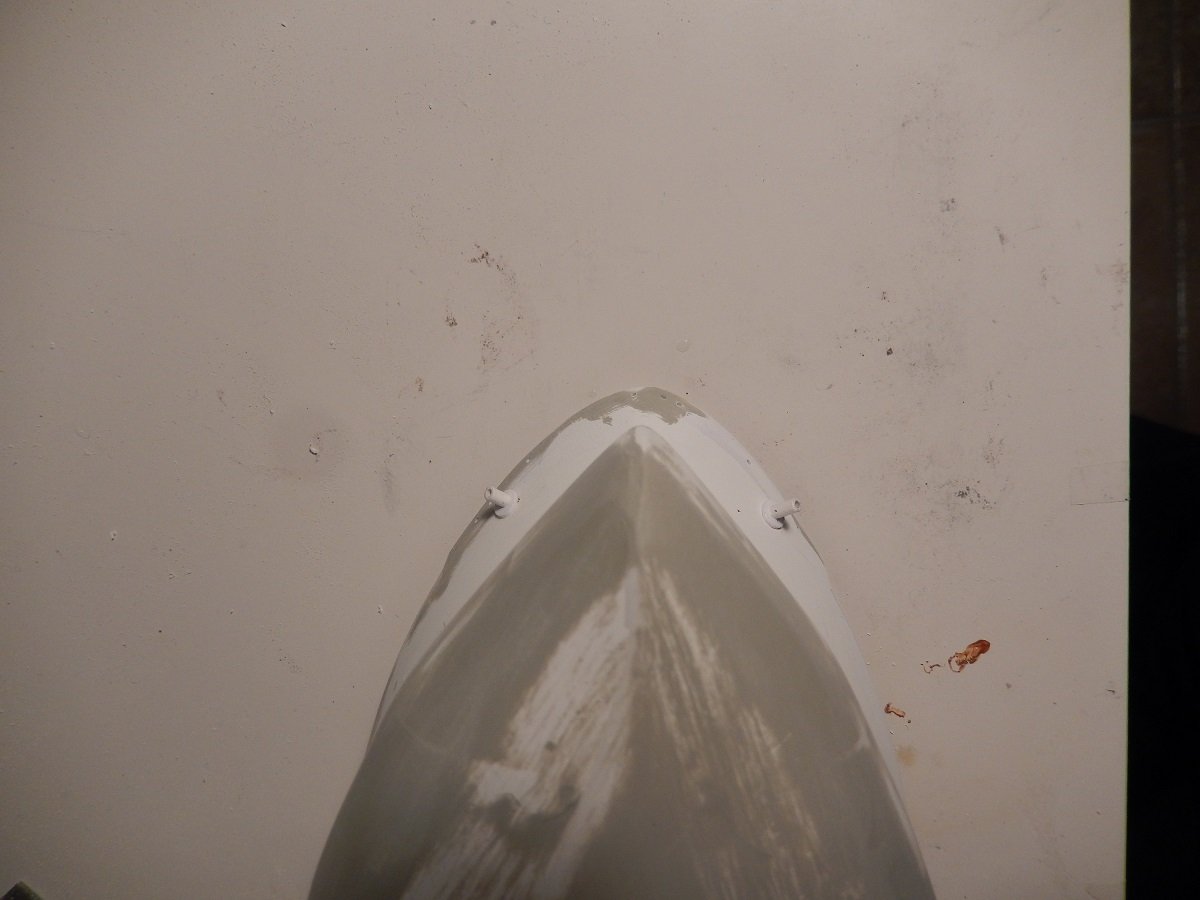
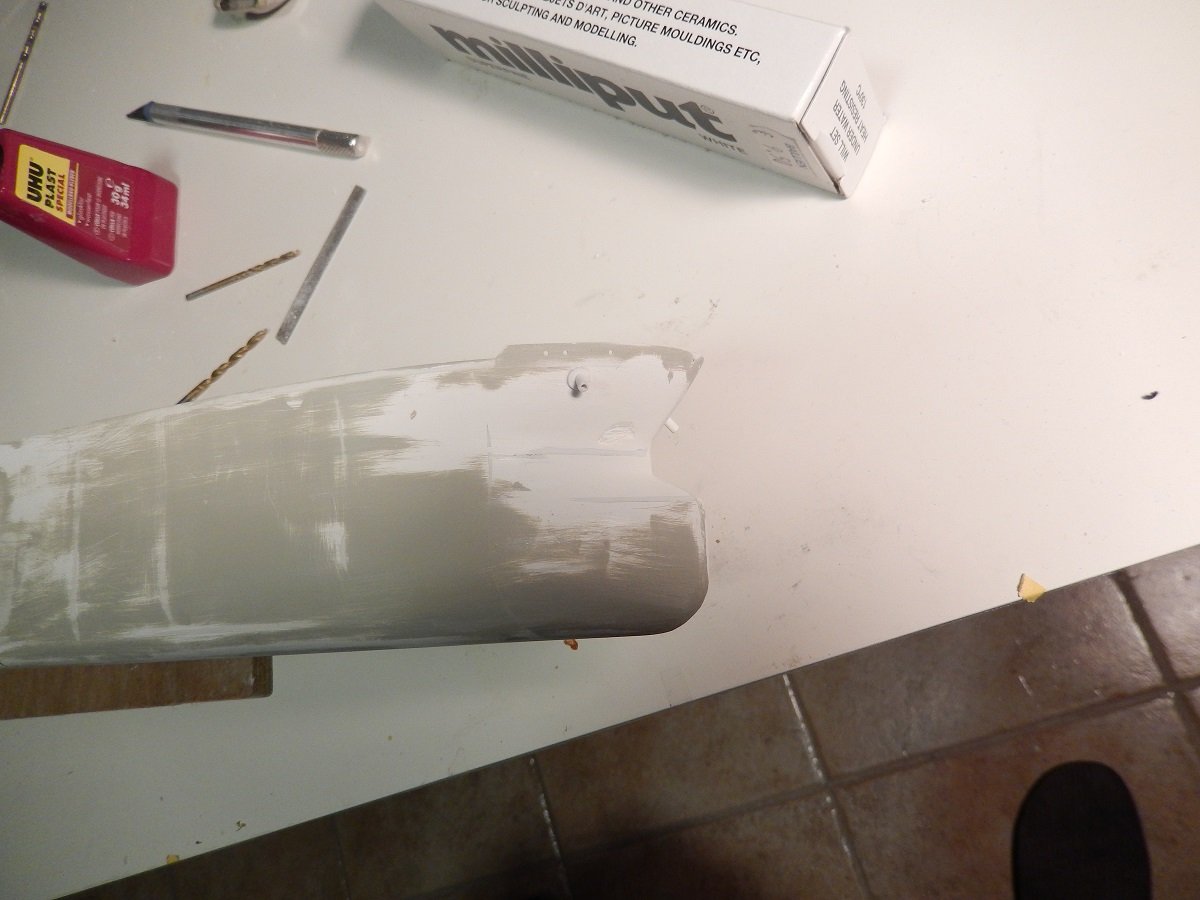
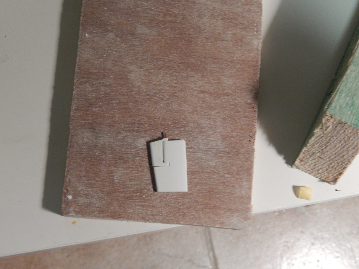
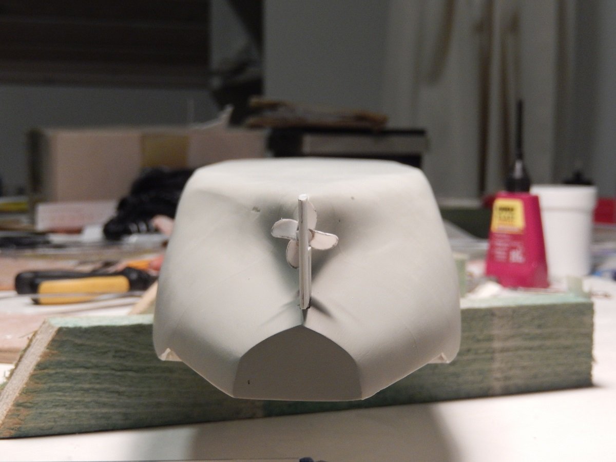
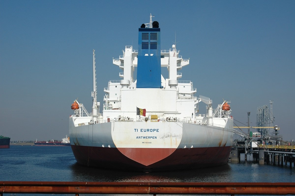
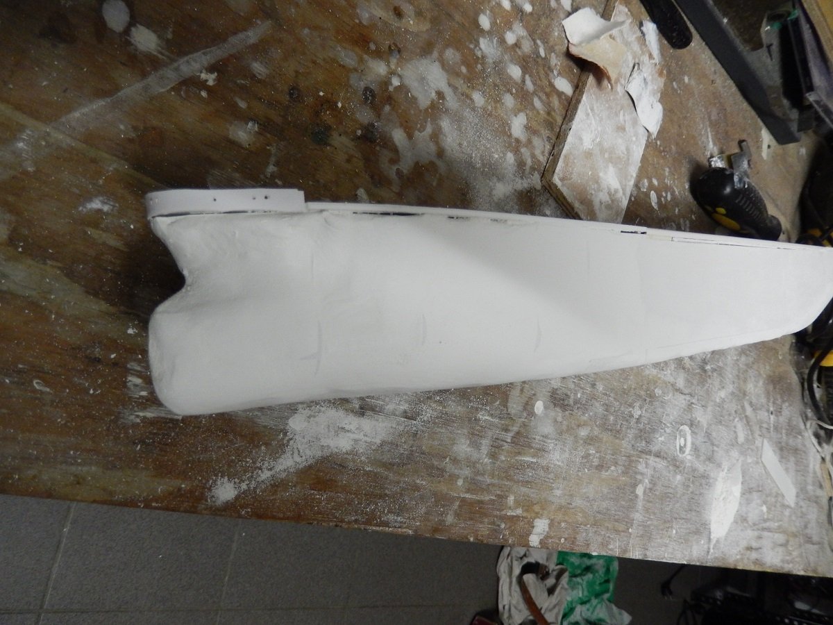
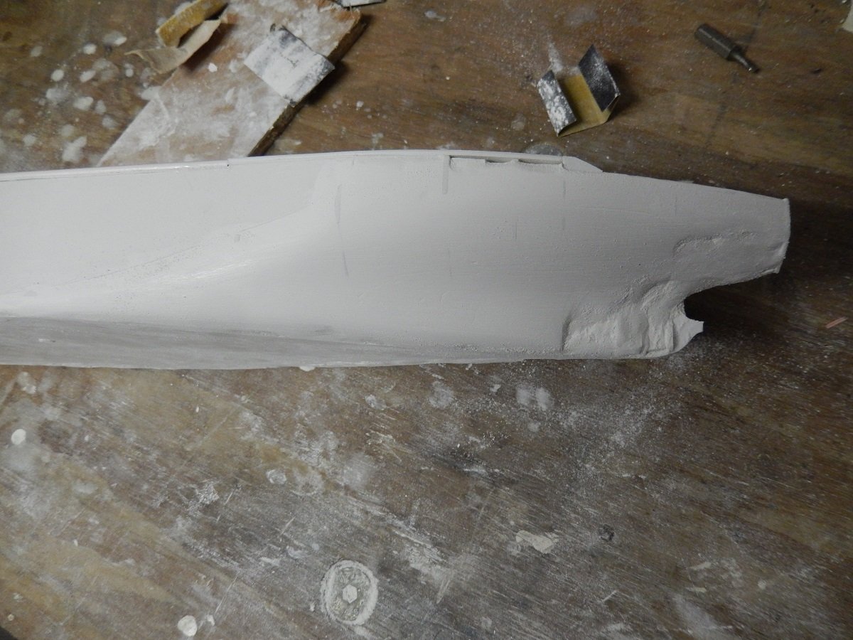
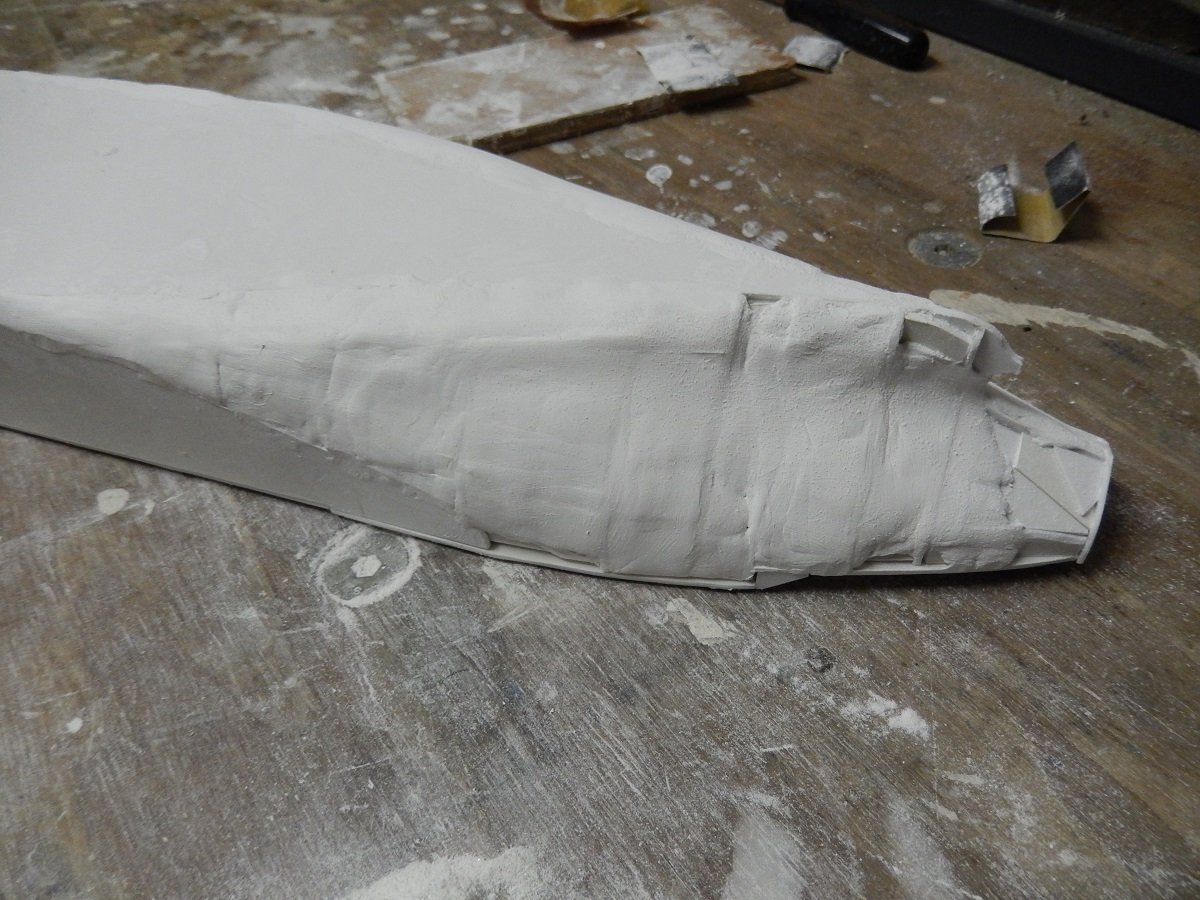
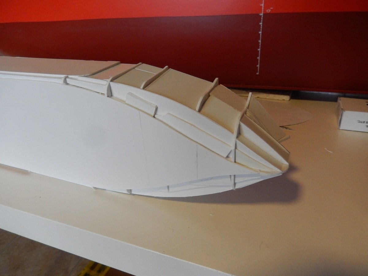
Next step is actually sanding off that filler/primer again to show where the bad spots are. It happens from time to time that there is a spot where the 2 components haven't mixed well and soft spots appear. In this case it's not very surprising that this happened due to the large amount of filler needed. If I encounter such a spot, I immediately see it when I'm sanding and I scrape it out with a knife until I hit hard edges. I then refill it with a smaller and better mixed amount of filler. On below picture you see such soft spot just on starboard of the stem, here I already removed some of the bad mixture. In following picture you see a spot where not enough filler was applied and a "hollow" was present in front of a frame. It shows immediately by keeping the dark colour of the primer/spray filler and getting a rather sharp outline. So extra filler was applied. and sanded smooth again. In the above pics you can also see the start of the "warts" for the anchors. To keep the anchors from hitting the rather large bulbous bow, the hawse pipes extend beyond that bow. A lot of work for a hull, but since the build is 90% hull, it should also look accurate. After the main hull work came the rudder and prop. I made the prop of 0.3mm styrene. Luckily it's a gigantic propeller in real life, so making a model of it still results in a decent size propeller (same in fact for the rudder). And a picture of the real backside of the vessel during one of her rare actual port calls. You can see how wide she is by looking at those lifeboats and the distance between them...
-
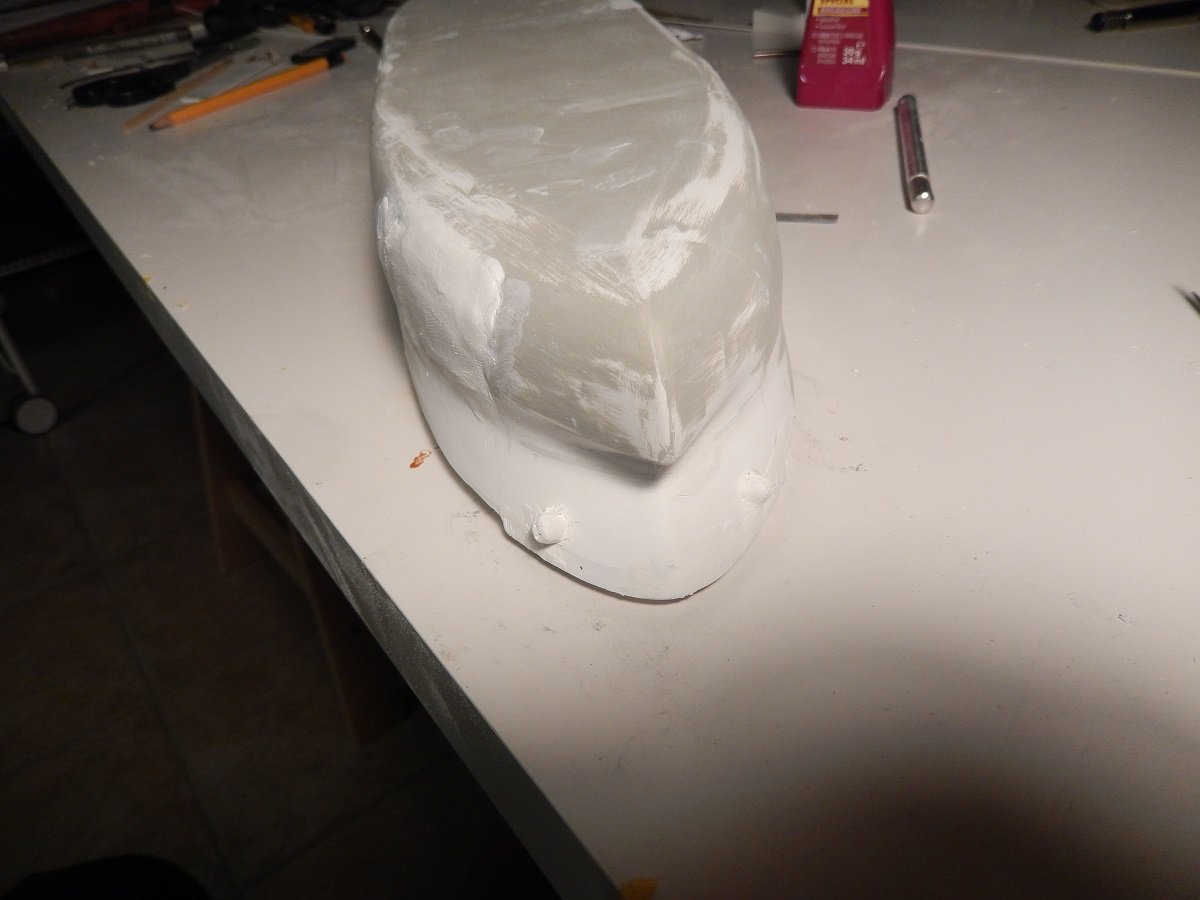
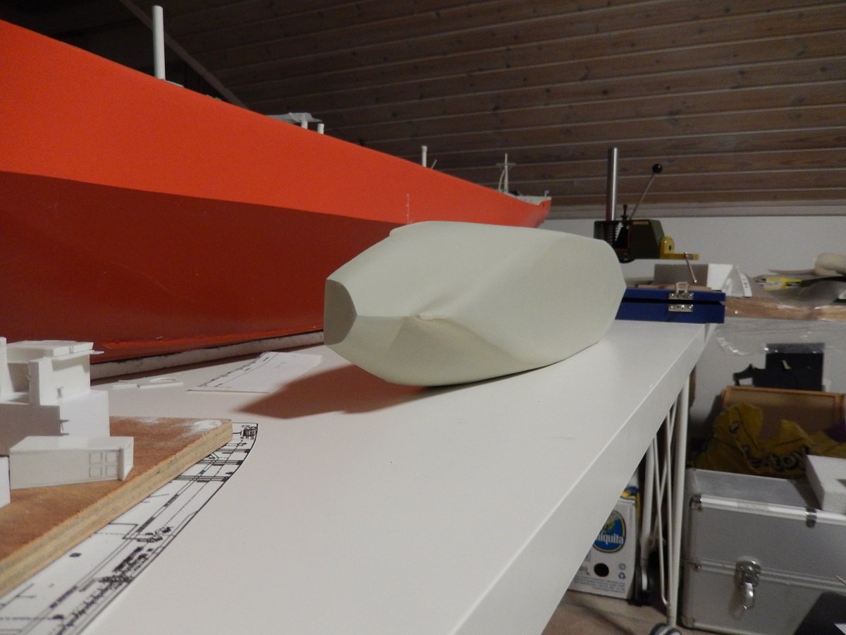
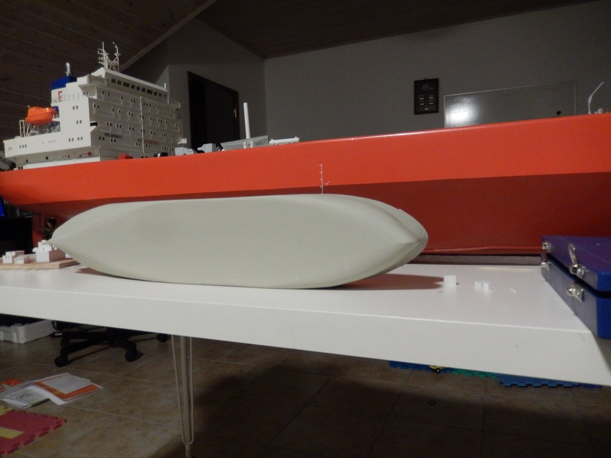
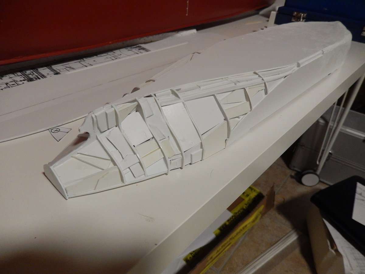
Thanks Glen, have no fear, I have obtained quite a collection of interesting bottles nowadays, each one screaming for me to put something inside. 3 of them actually have a very long body with a short neck, ideal for putting and manipulating a ship inside. I've been making plans for this and one of them will likely be a sailing vessel, following your lead. Next phase of this build was the filler. After many builds I've given up on trying to do this in 1 go. It's a dirty job, mixing the epoxy filler and applying it, so I'm always postponing this and trying to do it in 1 time, mixing decent amount of filler. However after sanding, I always end up with spaces requiring more filler... In any case, here was the first coat of filler pressed on and around the frames. And after a first rough sanding, to determine where more filler will be needed. And the white blob slowly starts to look like a ship. And after more filler, I decided to get going with spray filler. Something I had used on one build before, but that has become a standard practice on my builds by now. It fills up small gaps etc. while making any deficiencies pop out and it allows for smooth sanding. In this build it also showed some areas that needed improvement, so it was definitely not ready yet. It did start to show the typical voluminous tanker shape.
-
So much effort in that ensign, but the result is fabulous. The structure really appears a fabric rather than simply paper or plastic.
-
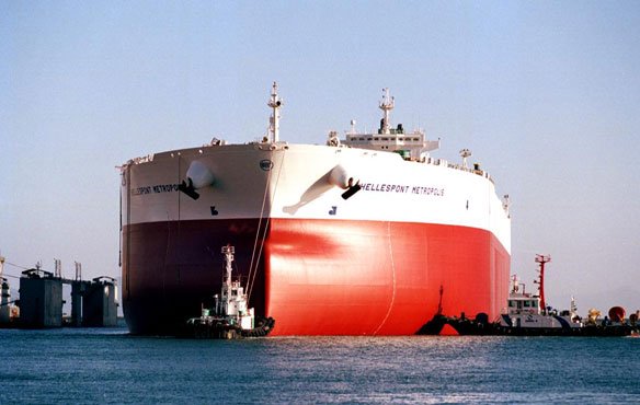
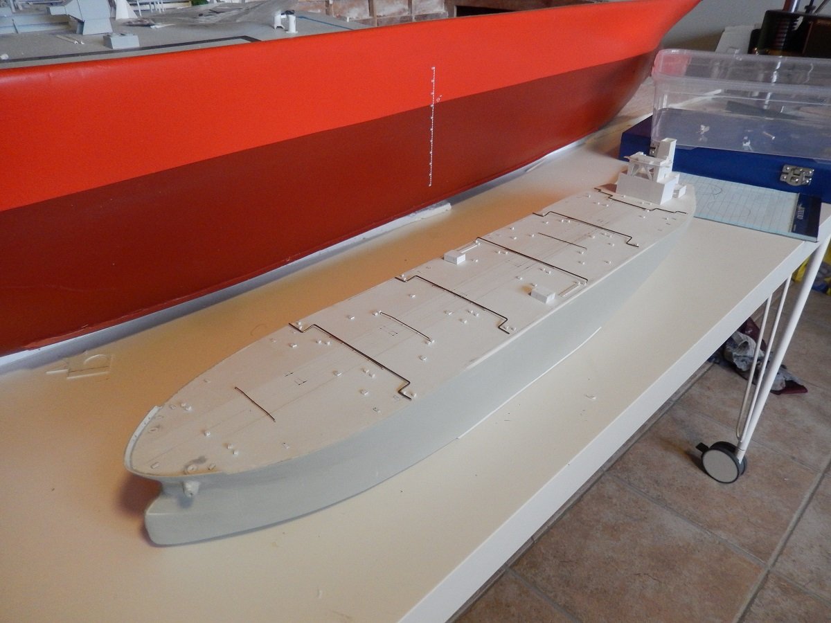
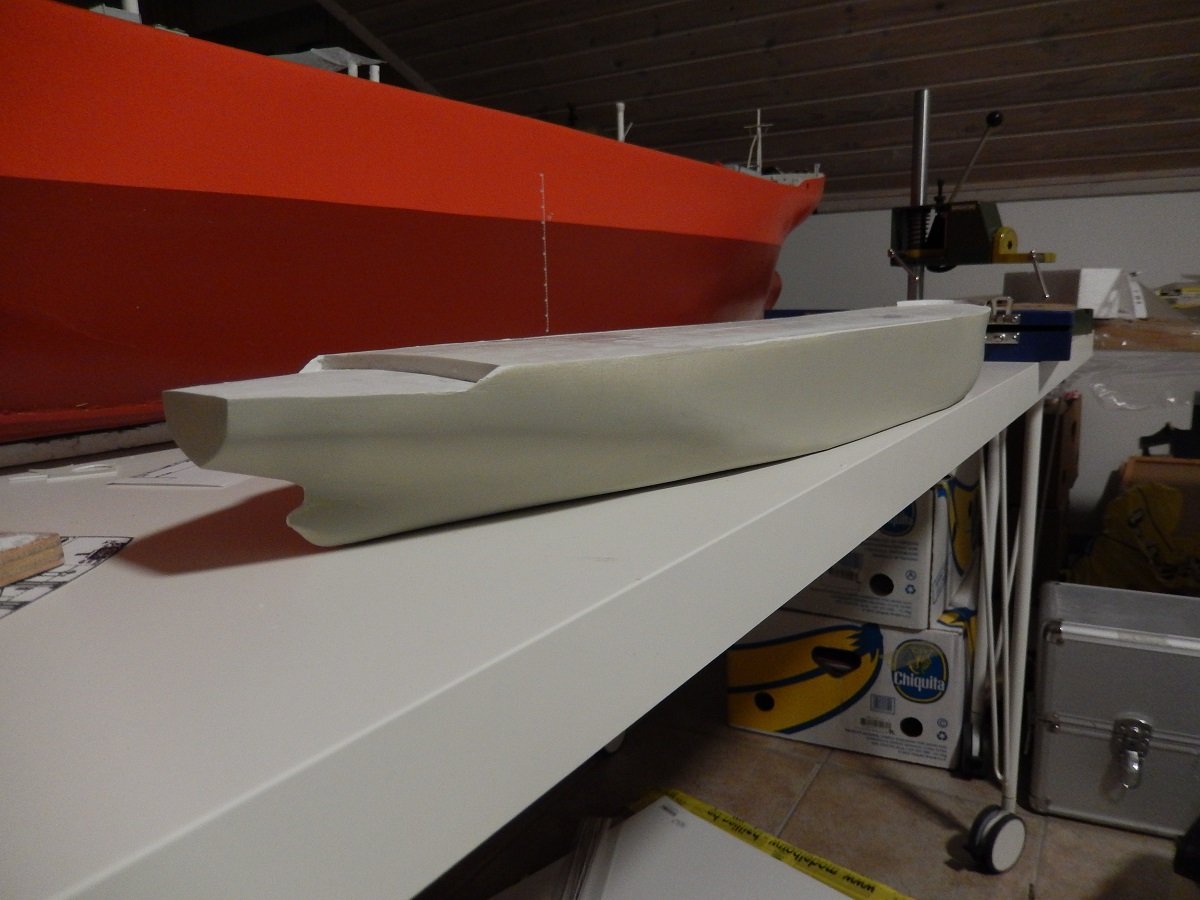
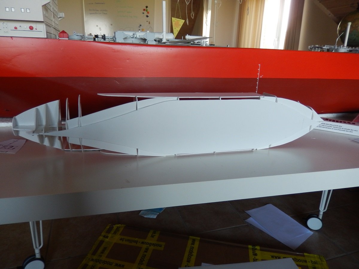
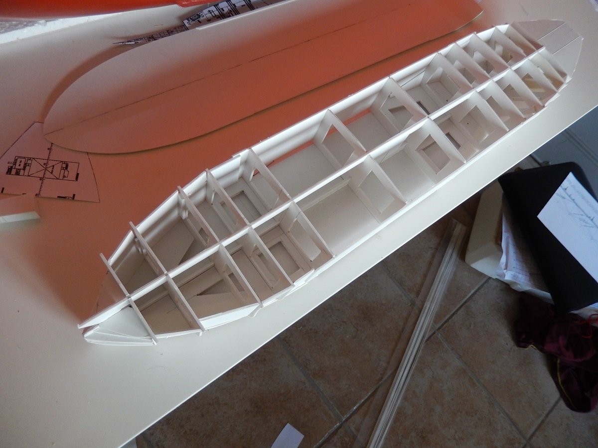
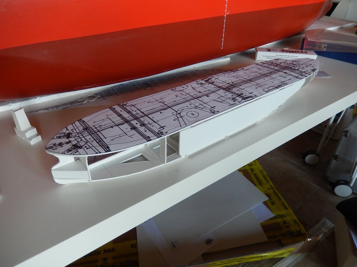
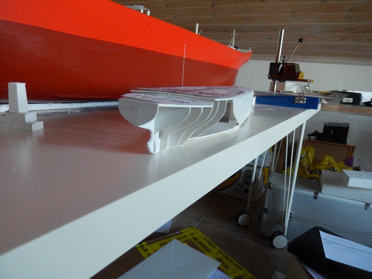
Great to see more models of these ships. I see the one in your picture is TI Africa, which I believe now is known as FSO (Floating Storage and Offloading) Africa. As you can also see in these vessels they don't have the regular huge bridge wings like VLCC's. Due to the presence of camera's around the vessel, she received an exemption of these bridge wings (used to look along the vessel during mooring and sailing). You can also see the big gap in the accommodation, the crew is quite small on tankers nowadays, yet there is a rule for view from the bridge towards the bow, you need to see any vessel/object passing 500m (or 2 ship's lengths, whichever is the smallest) in front of you. This means that for a big ship like this, the bridge needs to be quite high up, resulting in a pretty big accommodation. Since there was no need for a large accommodation, they made that gap in the superstructure, to both have a high bridge, but still limit the amount of internal accommodation space. One of the legs of that bridge houses a staircase, while the other side houses an elevator. Back to the model. I continued adding the frames and outlines, including the bottom plate. You can also clearly see that the stern is a lot more sleek and slender than the bow below the waterline. This is actually the case for most merchant ships, but it's not always this pronounced. I normally use this method of construction for smaller ships, but on such a large vessel, filling in the space between the frames is even more important before applying any filler. On smaller vessels I use mostly scrap pieces of styrene that I cut some angles off etc. Kind of like a jigsaw of scraps. This helps to avoid large amounts of filler. In this case I did actually cut pieces of styrene from a new sheet to fill most of the space near the bow. For the stern, I did use more scrap from my scrap box. Since the two component epoxy filler I use is rather difficult to manipulate, I used some reinforcements on the edges of those filler plates to avoid them being pushed in when I apply the filler. This happened sometimes in the past, when my scrap pieces were not well fitting for the space they occupied. I don't care too much about having a perfect match, small holes and gaps will be filled by the filler after all. You do however need some gluing surface if you want it to be sturdy enough to push the filler around.
-
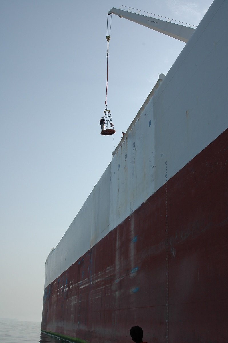
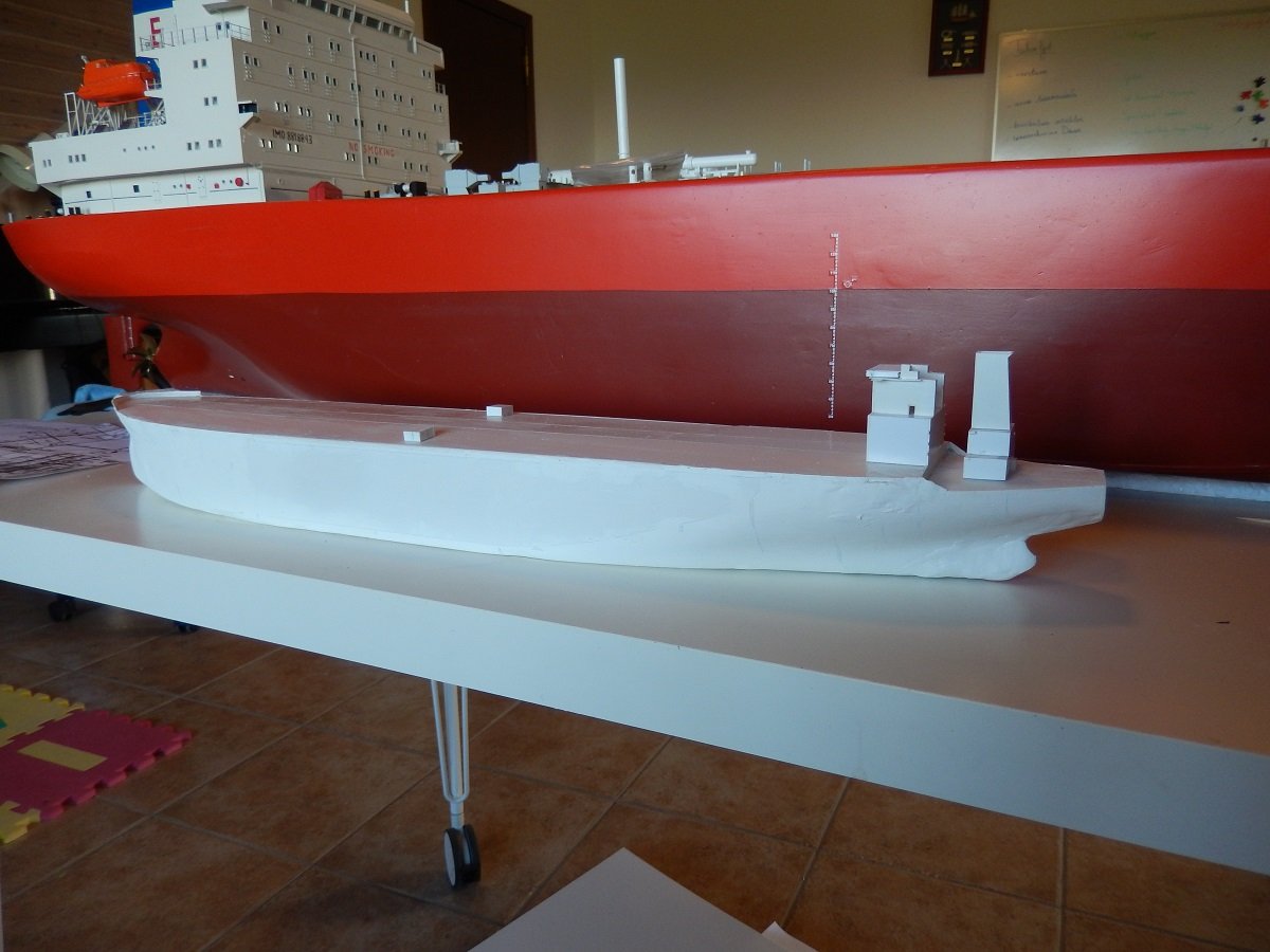
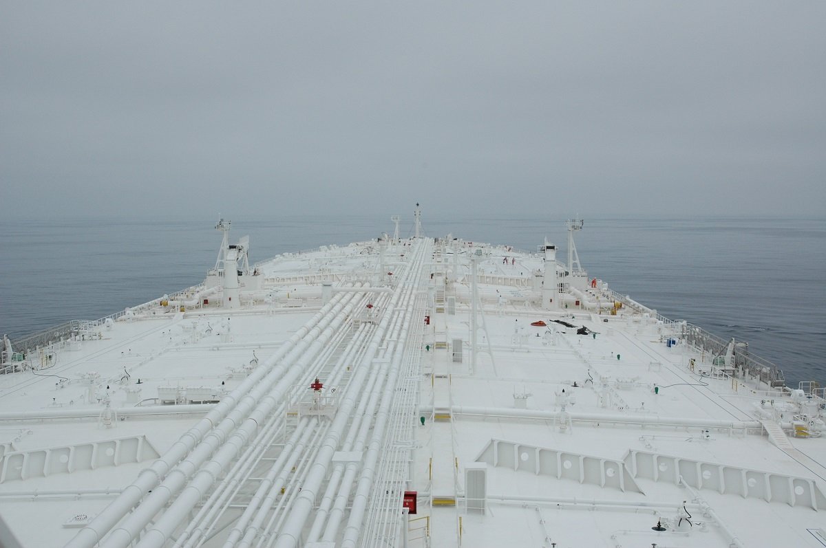
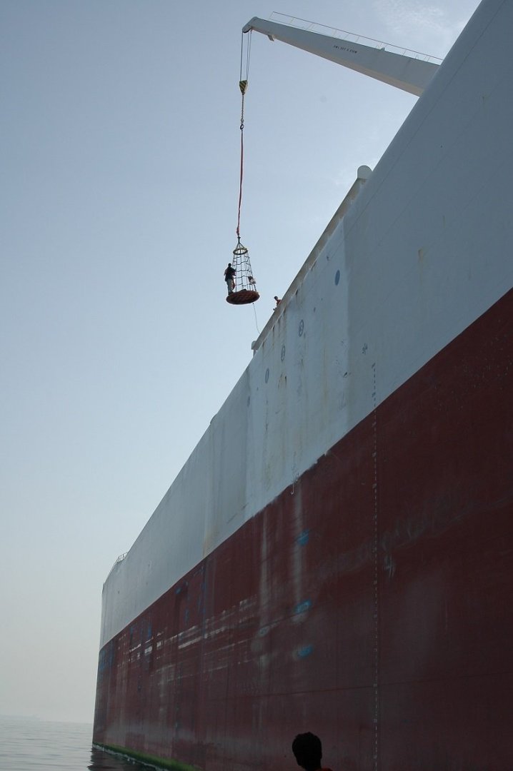
In my haste yesterday, I forgot to add a couple of pics of the real thing. So here we go. When you see it in loaded condition from a distance, it looks rather flat and not so big, but once you get closer, you start getting an idea. It's ok right? Until you realise those orange dots on the starboard side midship and forward are actually people. You can also see the small hiding shelters amidship and the big wavebreakers on the deck. Those hiding places are necessary as it takes a long time to get from forward to the accommodation block. In ballast condition, disembarking is not for the faint hearted. So why the white? Well, we used to say, hospitals are white too, to keep the patients calm... But the real explanation is that the color was chosen to reduce cargo boil-off. Oil tankers have quite a reduction in amount of cargo due to boiling off of the lighter elements in their cargo. Pressure inside the cargo tanks starts to rise because of that and eventually it blows off through overpressure vents. Over such a large surface/structure, the colour actually did make a difference, probably also the reason why it was never changed, eventhough the ships changed hands several times. They were actually built too late. The heyday of oil tankers was already over by 2000. ULCC's were a thing of the past, as a cargo volume of 3.2million barrels of oil made it very expensive to load these beasts, while the amount of ports and voyages was limited. Nowadays some of the sisters are used as Floating Storage Units in oil fields, while on Europe (and perhaps Oceania) are actually used for transport. One big advantage of such subjects from a modelbuilding point of view, is the large "parallel" surface. Something most merchant ships have as it helps them to moor safely. These are often also drawn on the plans and make their box shape easier to build, only really requiring frame shapes forward and aft. I didn't actually have many plans to work from, but I combined all sorts of shapes I had from those plans. I therefore combined frames as well as floor outlines and heights to get an accurate shape.
-
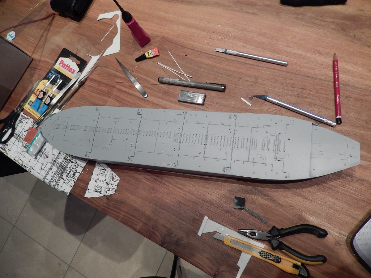
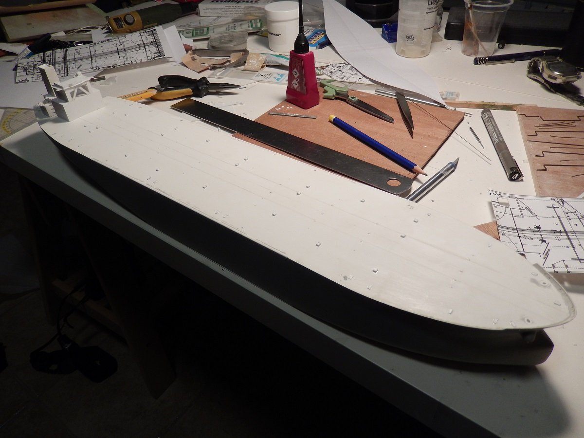
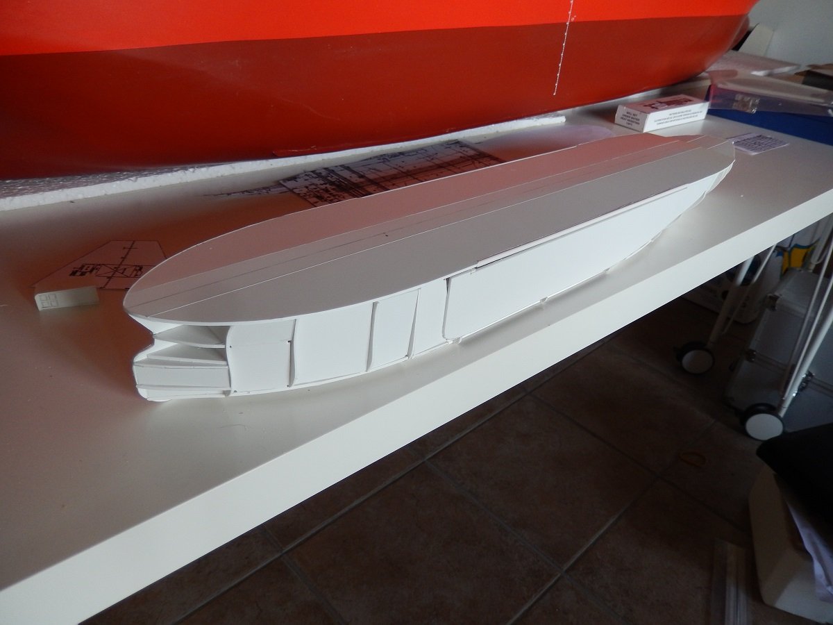
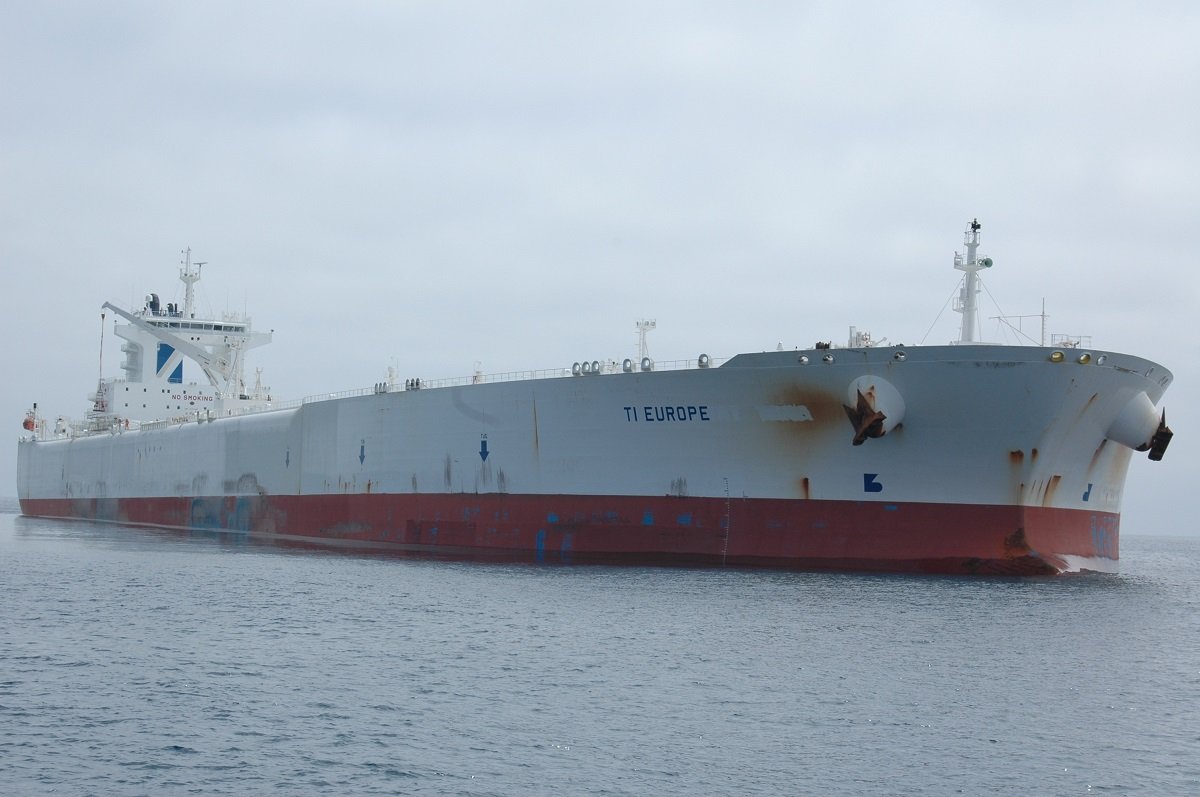
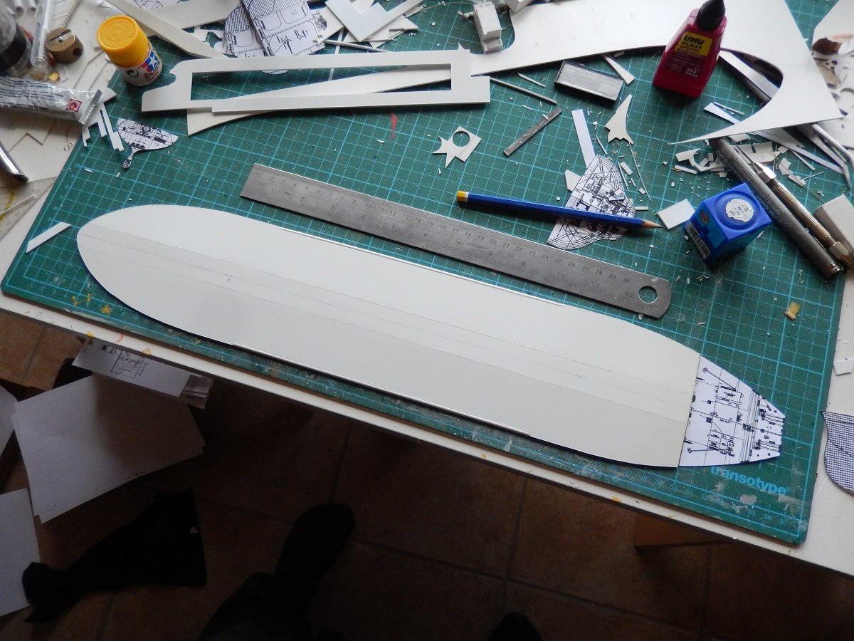
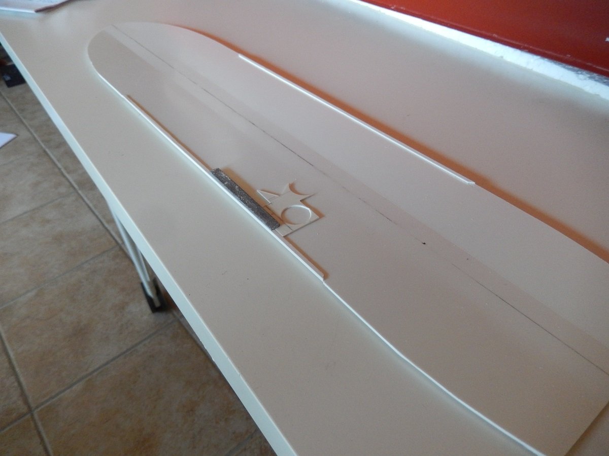
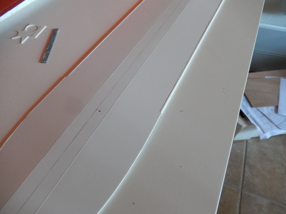
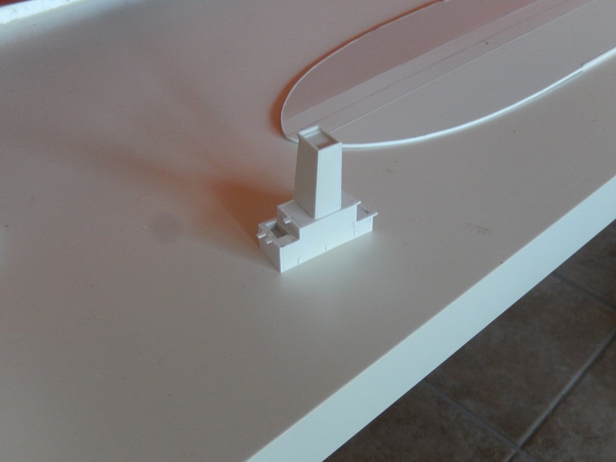
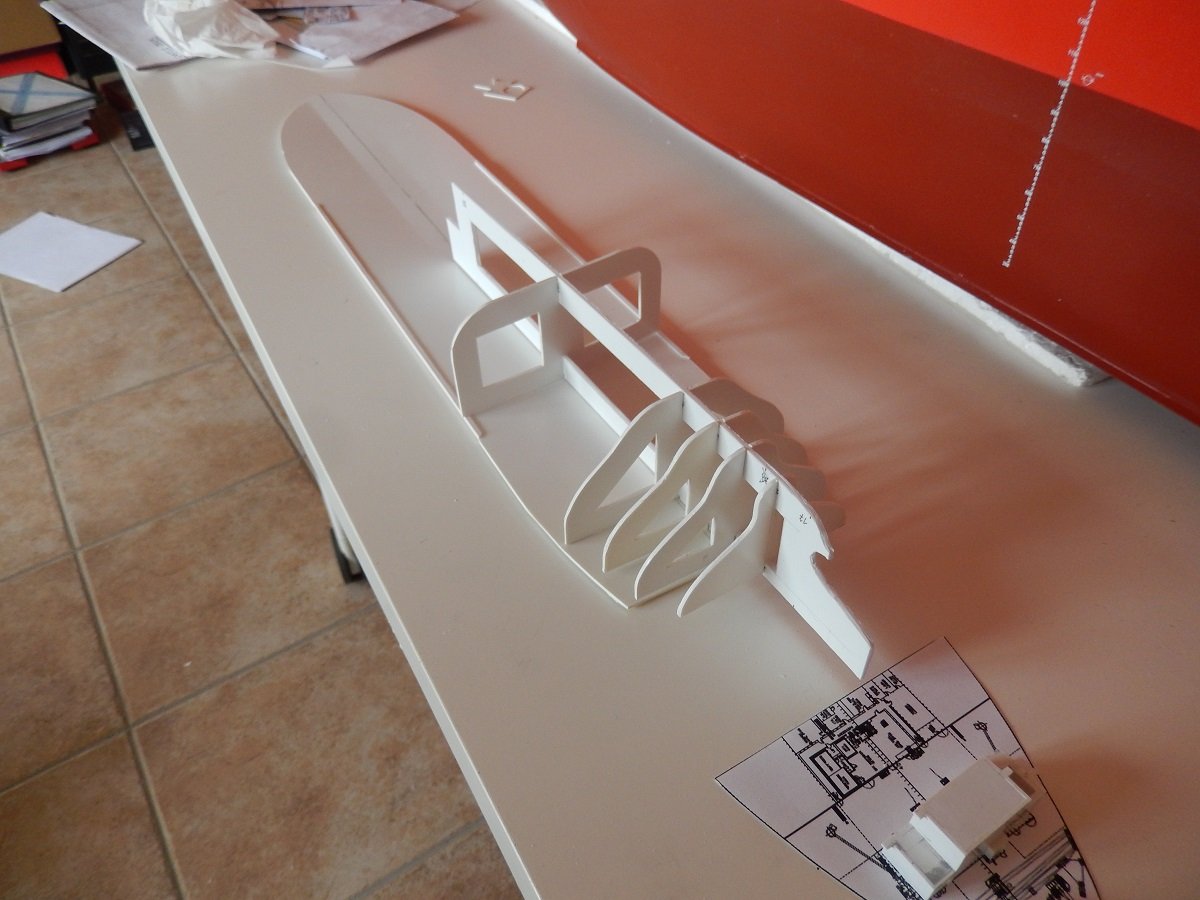
Well since I'm longer onboard, without the possibility to show new progress. I'd thought I'd fuel @KeithAug newfound love for complex piping a bit further. I consider this build, for an unknown reason, still as one of my best builds. It's an eye catcher in my display closet, probably by its color and size. As the title says, I'm talking about the TI Europe (TI standing for Tankers International, an oil tanker company pool). The TI Europe is an Ultra Large Crude Carrier, one of 4 sister ships built by the Korean Daewoo yard. They were built for the Greek company called Hellespont, but were sold after a few years to the larger company called Euronav and renamed as TI Africa, TI Asia, TI Europe and TI Oceania. TI America was deliberately left out for fears of terrorist attacks since this all happened in the beginning 2000's. When built they were the largest double hulled ULCC's in the world and still are some of the heaviest ships around. Their size, 380m (1247ft) long on 68m (223ft) wide, was huge for those days (nowadays however this is not such an exception with many container ships measuring around 400m long x 56m wide), however their full load draft of around 24.5-25.5m (80-85ft) made them huge. With that full load draft they were unable to pass Singapore Strait, the English Channel etc. in a safe way. Due to that size, they were also restricted in amount of ports that they could enter. These vessels weigh about the same as 5 US Carriers together when fully loaded. When I went onboard, we were doing Ship-to-ship transfers off the coast of Los Angeles to smaller vessels. The voyage then went to Saudi Arabia, where loading happened on buoys connected to the actual terminal by submerged pipelines. Other voyages she often did, took her to Europe, discharging part of her cargo in France before transiting the English Channel to go to Rotterdam with the remainder of the cargo. The model. I built her, using the experience I built up with frame on keel methods from plastic. Size and rigidity was the real challenge here. Since that's also an issue in the real design of such vessels, some solutions were given by the original. The main deck of the beast, can easily fit a US CVN on top of that deck. I've made the main deck of 1.5mm styrene, this was still not very rigid over such a length. However, on the real ships, the corners are rounded, this help divide the forces over a larger surface instead of a single angle. A square angle would simply break loose under such forces. To simulate this rounded corner, I cut a piece of styrene rod and glued it flush with the deck. This added to the rigidity of the deck where it was most needed (the central part). Additionally you see the deck is divided in 3 parts, creating a camber like the real ship. On the real thing, that camber is truly large as well. Then I started building up the skeleton structure bellow, using the table surface and deck to keep everything flat. At the same time I started building the (small-ish) superstructures for this vessel. That's it for today. Since I can't get home for a while, I'll continue soon.
-
Spartacus by Javelin - 1/2000
Javelin replied to Javelin's topic in - Build logs for subjects built 1901 - Present Day
Hi Vinoth, are you talking about the real ones or the model ones? -
Thanks for that Glen. Basically how I made my crude hinges for Sea Installer then. They were far from perfect and luckily hidden by the casings on my model. Also thanks for pointing me to @John Fox III 's build. He cheated by putting "in a lightbulb" instead of bottle and avoided showing up in my bottle searches. That is indeed a work of art, I love his hinges and might have to try and steal that method ( but likely end up on a level of "doing the job" rather than a work of art as you mentioned).
- 88 replies
-
- 5
-
-
- Ghost Ship
- Jenny
- (and 1 more)