Daryl
-
Posts
71 -
Joined
-
Last visited
Content Type
Profiles
Forums
Gallery
Events
Everything posted by Daryl
-
Now that someone has mentioned ModelExpo and Paypal in the one entry, why doesn't ModelExpo use Paypal?? Certainly would help everyone especially those of us how have horrendous postage due to being international clients.
-
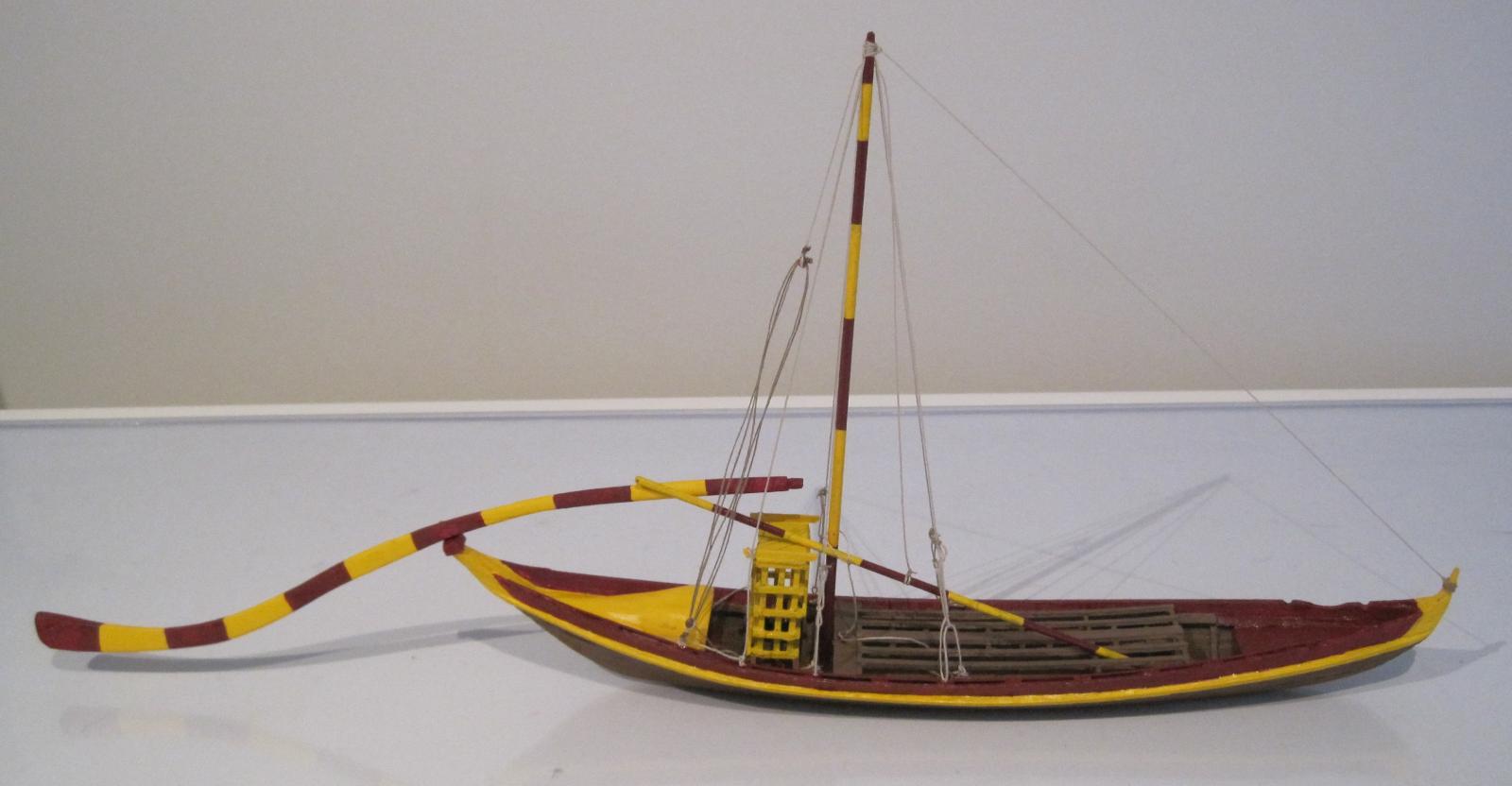
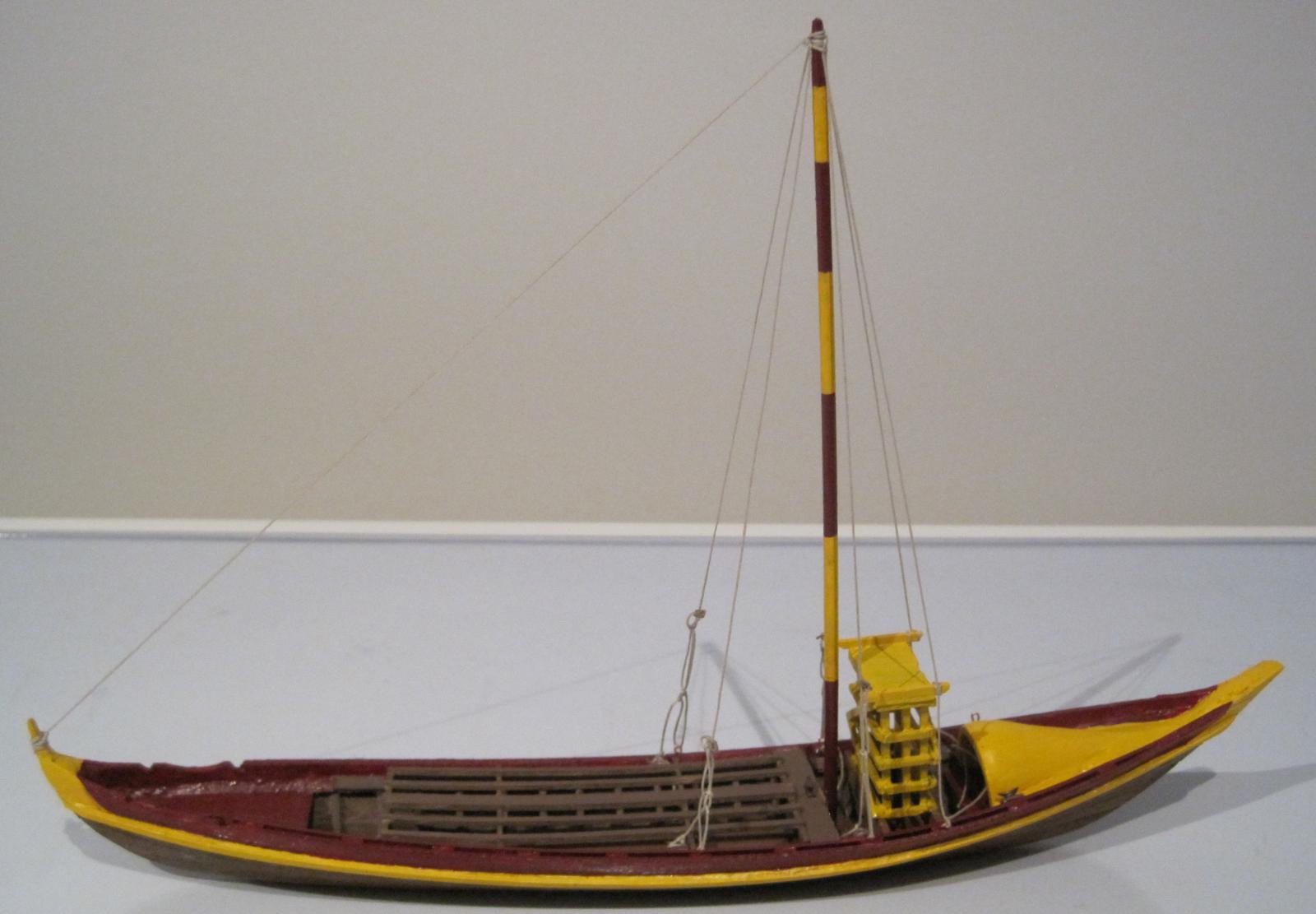
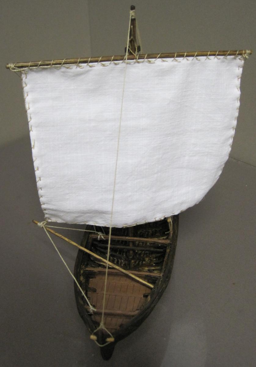
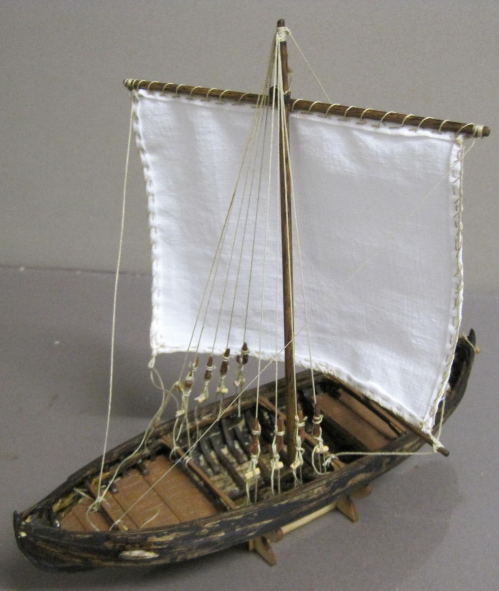
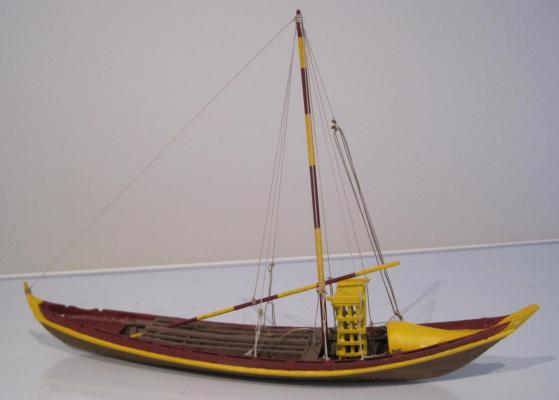
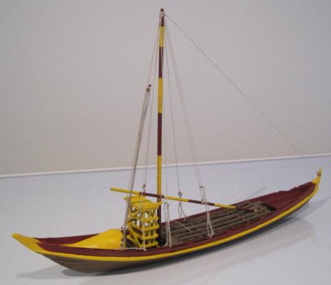
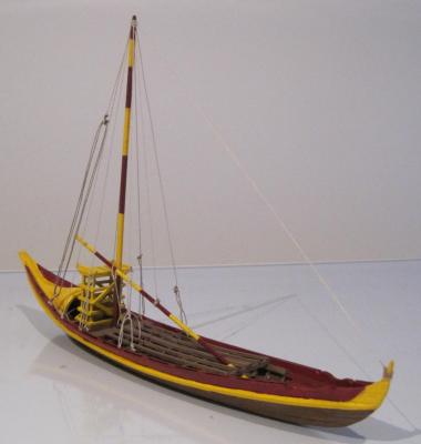
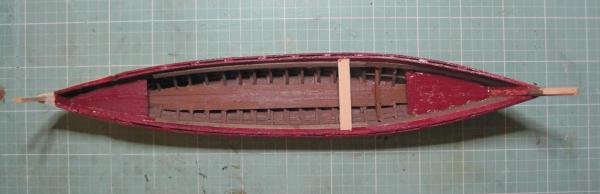
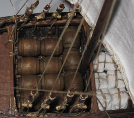
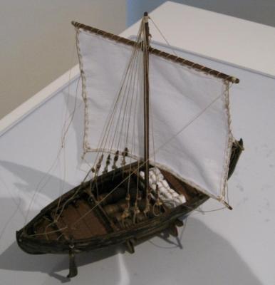
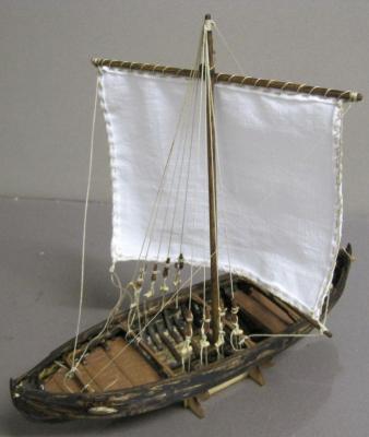
 With the exception of adding the port barrels and possibly a furled sail, the build of the Barco Rabelo is now complete. The barrels and sail give me another good reason to go to Float a Boat and see what goodies they have in store.
-
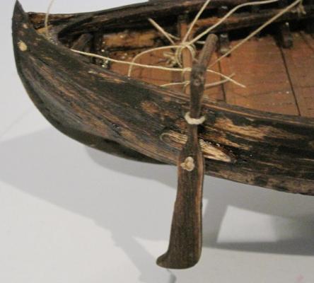
The rigging is now completed and if anyone has a very good understanding of exactly how a Barco Rabelo should be rigged, please let me know. The more detail you have the better, especially how it is all connected to the hull. I have decided to put the sail on hold and will now concentrate on making the Espadela/Scutcher (sweep oar). If I do put the sail on I think it will just be furled on the One day I will make another Barco Rabelo as I have learnt so much building this one I am sure I can do a better job next time around. That is why I would appreciate receiving any information that would be helpful.
-
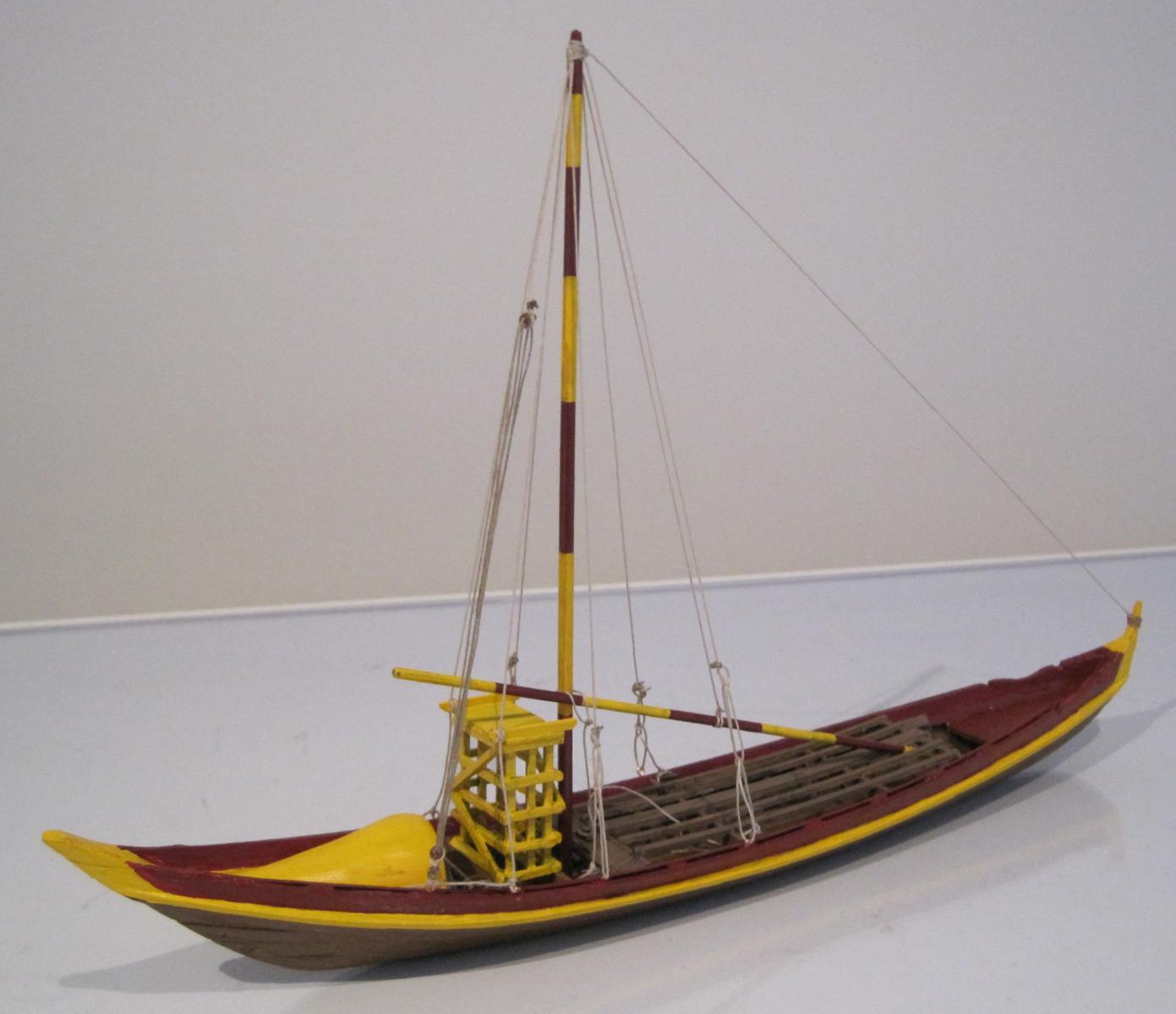
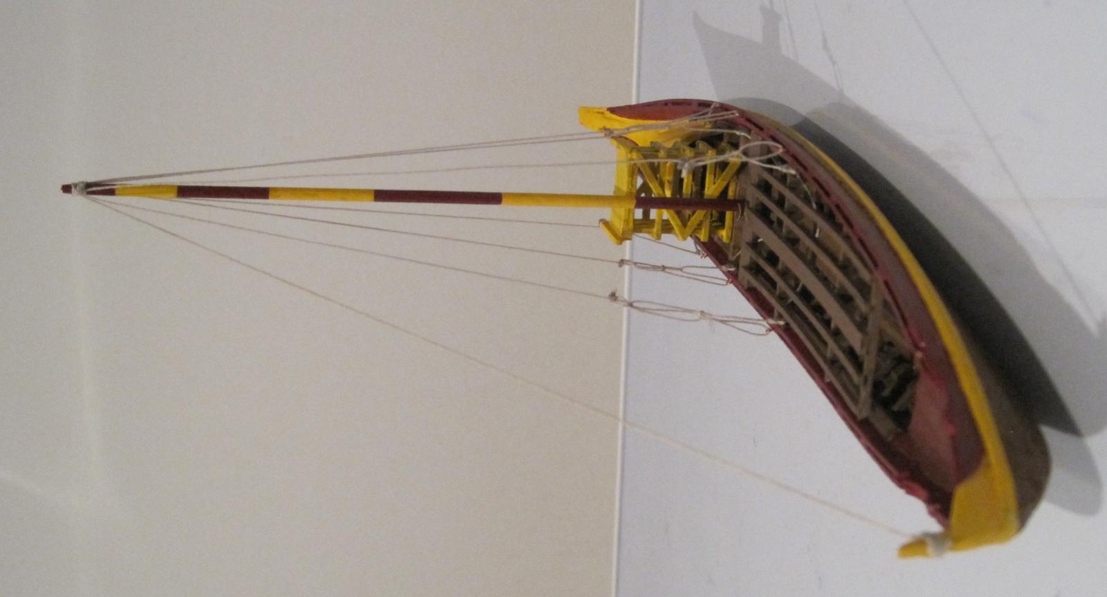
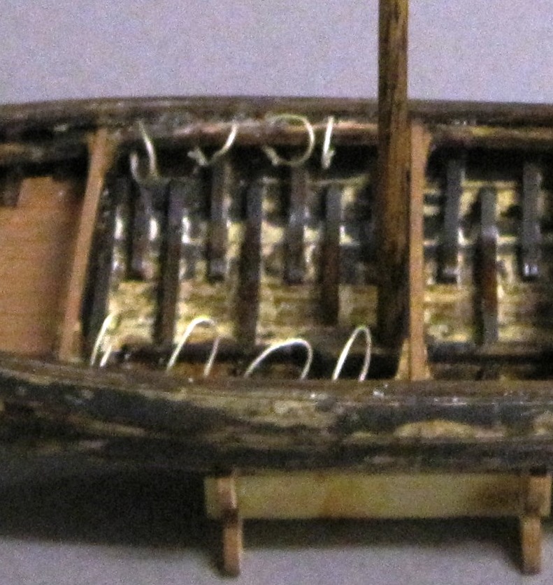
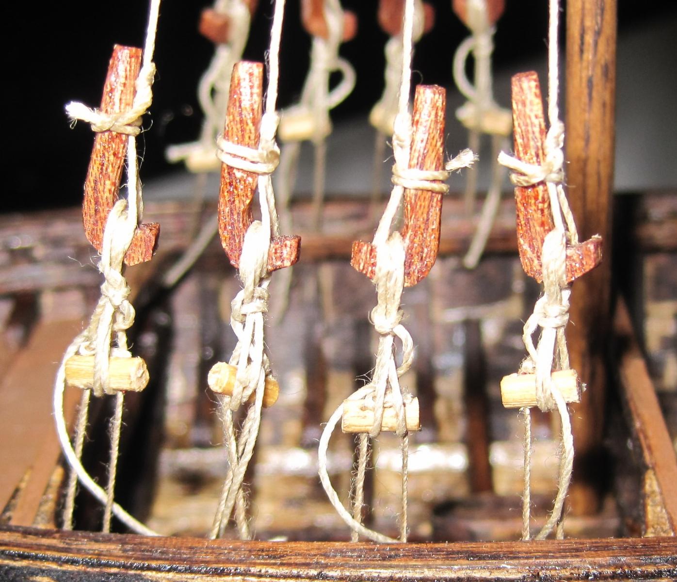
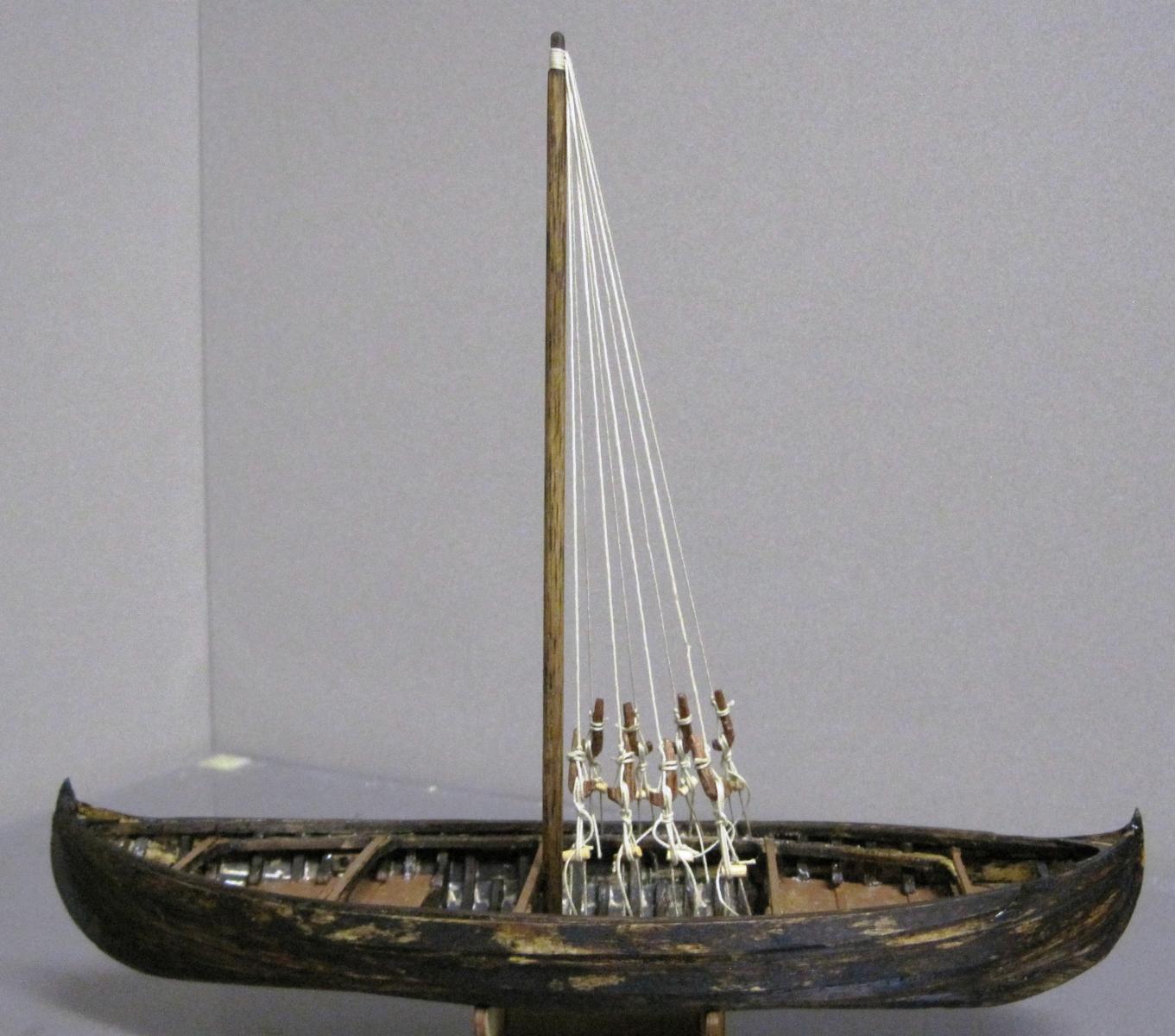
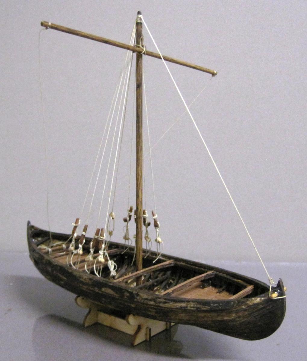
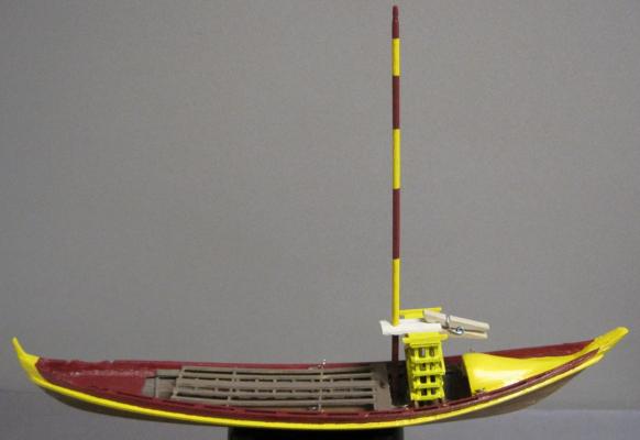
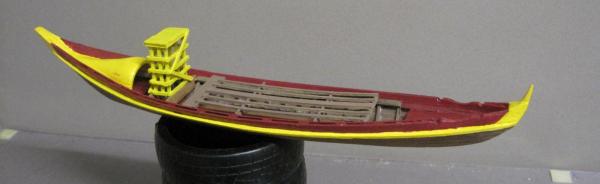
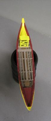
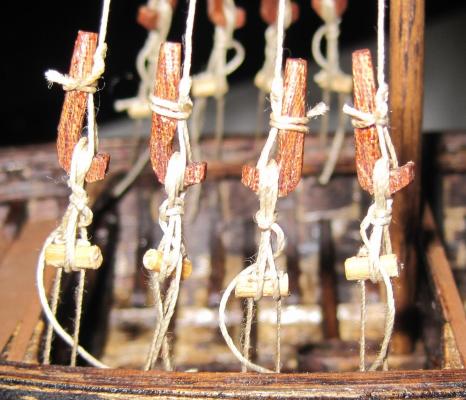
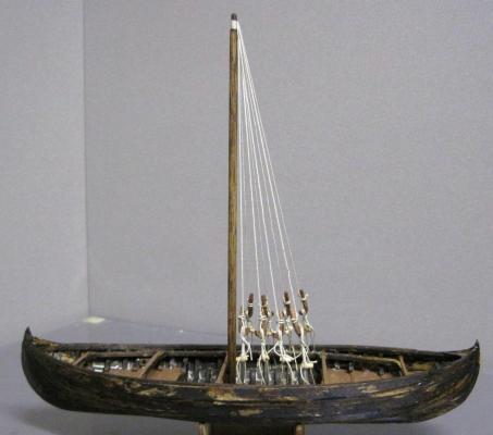
It has been another good day inside in the warmth. Went shopping at Float a Boat yesterday and stocked up on some bits and pieces. I now have the mast stepped and the Forestay and Shrouds installed. After looking at lots of photos and drawings I realised that even though the rigging seemed to be similar on all Rabelos, there were some differences. So, with that in mind, I am installing the basics but with a bit of a difference here and there. I was unable to find something that showed exactly how the shrouds were connected to the hull so I have taken the view that the shroud had a sheepshank (used for adjustments) that led into an eye and then it was tied off on a cleat. As these are working boats that have large wine barrels loaded and unloaded on them and travelled down a very dangerous river which subjected them to some damage, I decided to make the model not look perfect but to have a "used" look about it. As an example, you will note that all the sheepshanks are not exactly the same size and not perfectly in line. Two of the shrouds are mainly used to keep the platform in place, so maybe they could be called something else. I hope to finish the rigging (halyard) soon and then I can paint up a sail to go with it.


-
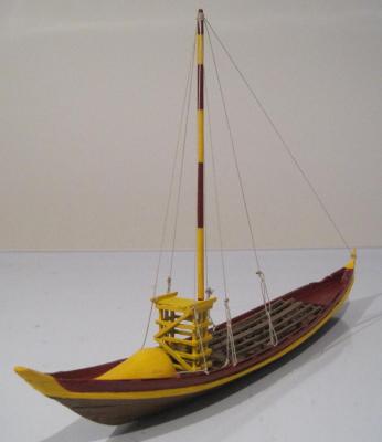
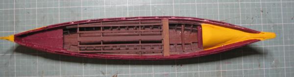
Things are happening quickly now. I have completed and installed the support infrastructure for the barrels, installed the Coqueiro, installed the Pegada (platform) and given the boat a complete new paint job. It is starting to look good. I have now started on the mast and rigging. Getting good information on the exact rigging used has been difficult but I think I have everything I need.
-
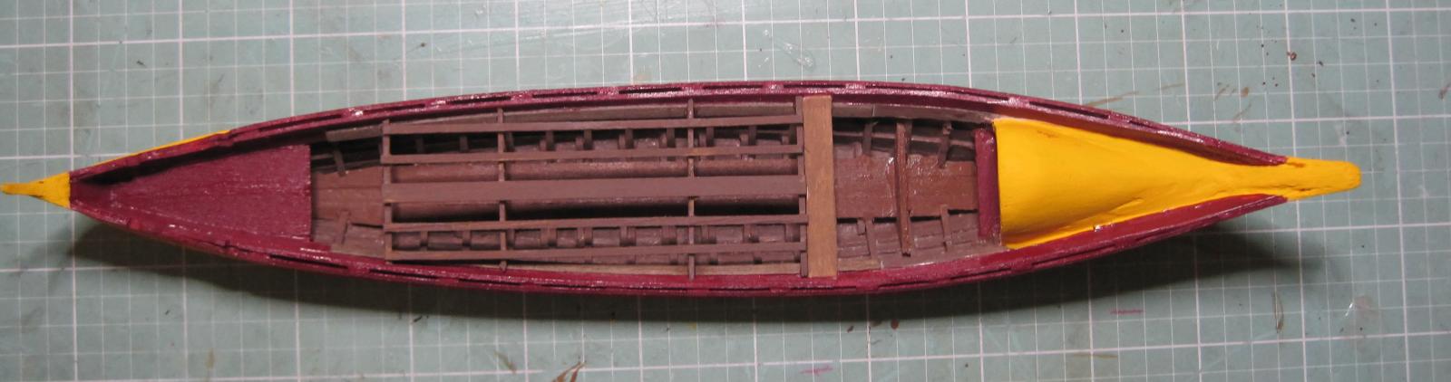
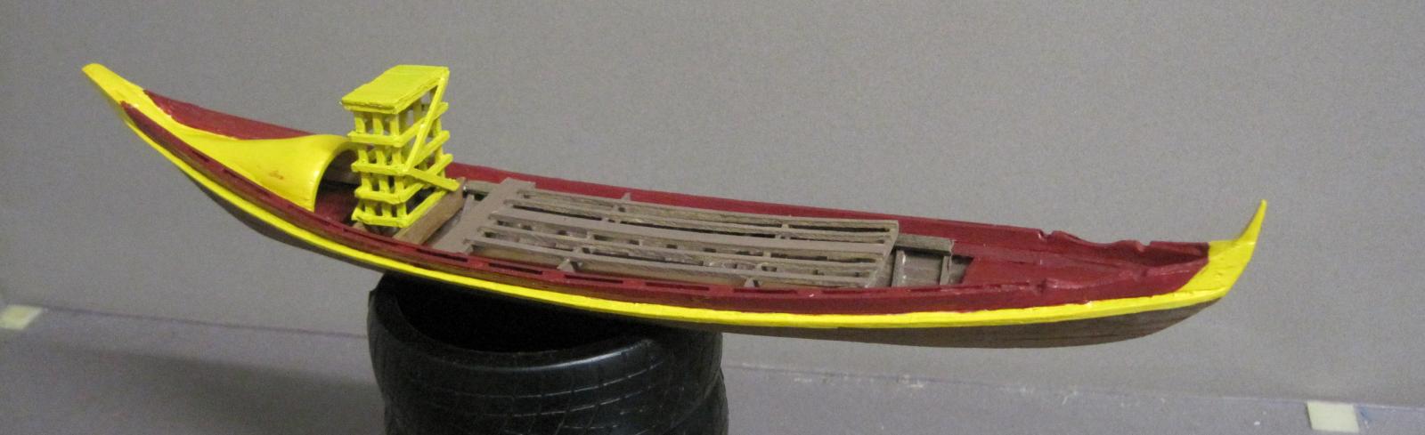
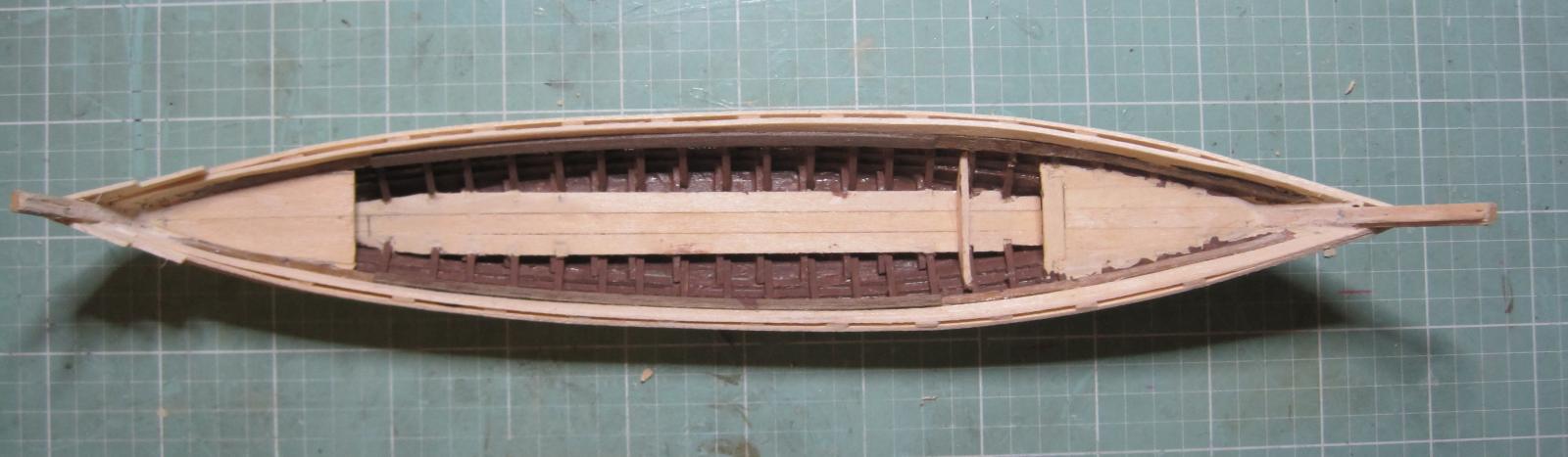
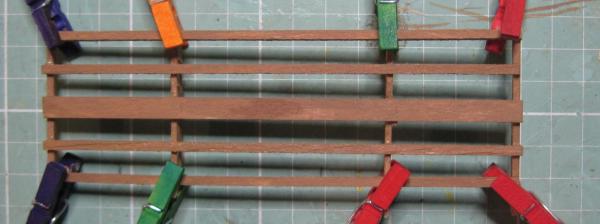
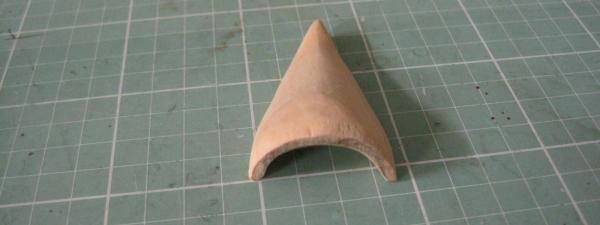
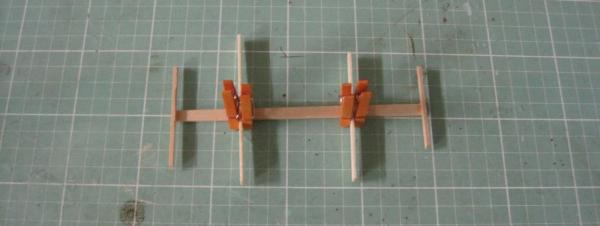
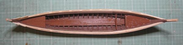
I changed the color of the decking to keep it more in line with the original Rabelo. Also painted the external trim the same color. There is some yellow coming so it should be very colorful when finished. The photo does not look the best and I think my trusty little Canon Ixus 95 IS has just about taken it last photo. I am sure the original Coqueiro (stern cover) was made from several pieces of timber but due to the size of the model, I decided to carve one out of a piece of huon pine. Pity it has to be eventually painted yellow as the pine looks really nice in its natural state. Next up is completing the framework that holds the port barrels. The great little pegs sure come in hand to hold the cross pieces in place while the glue sets. Should have the framework finished tomorrow.
-
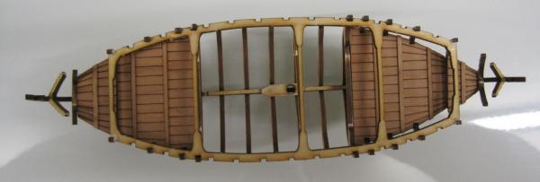
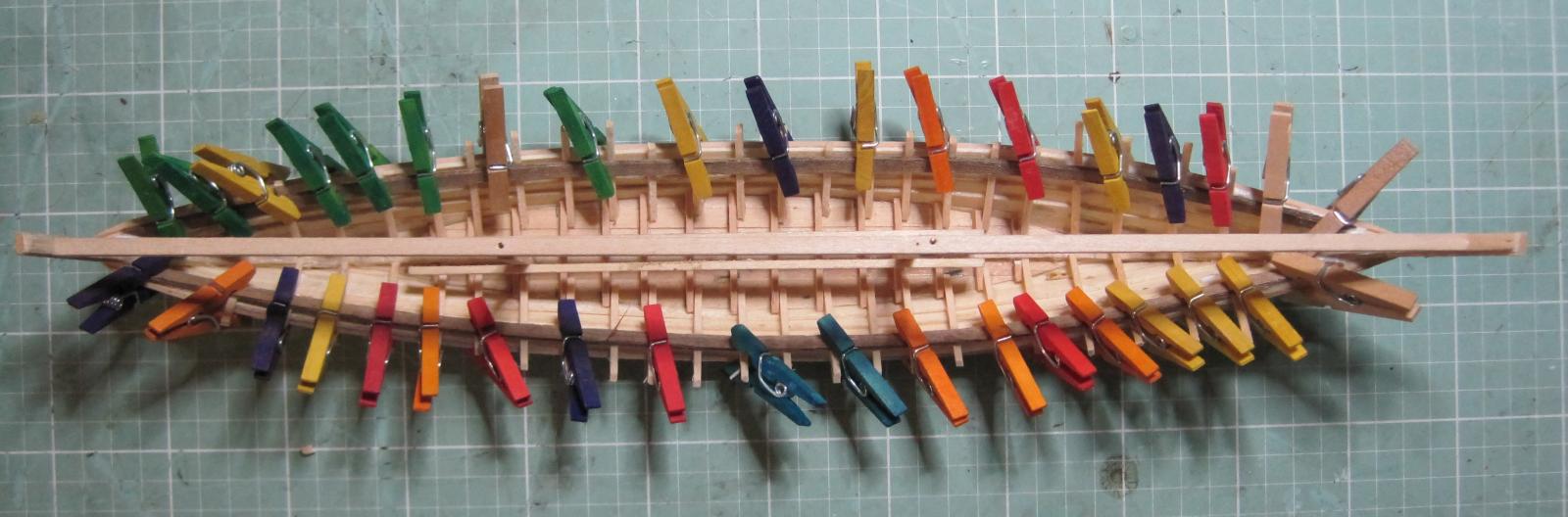
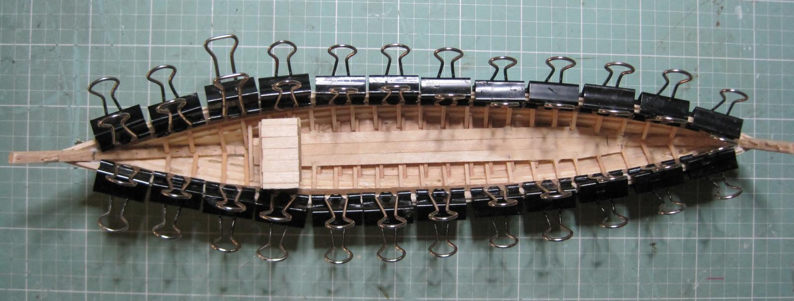
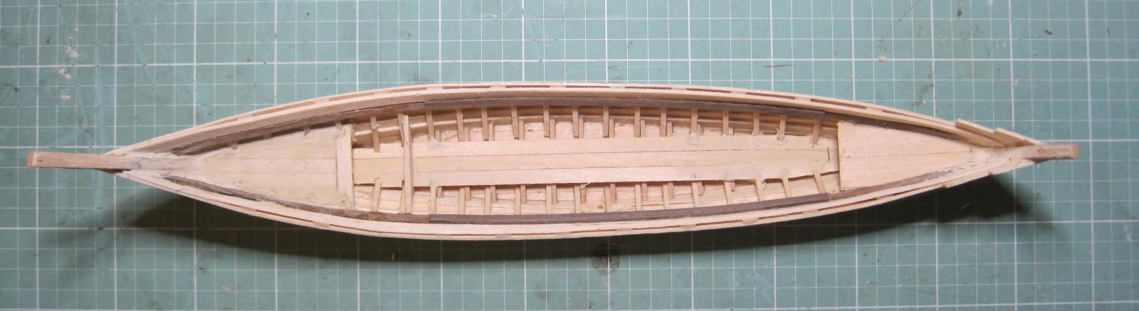
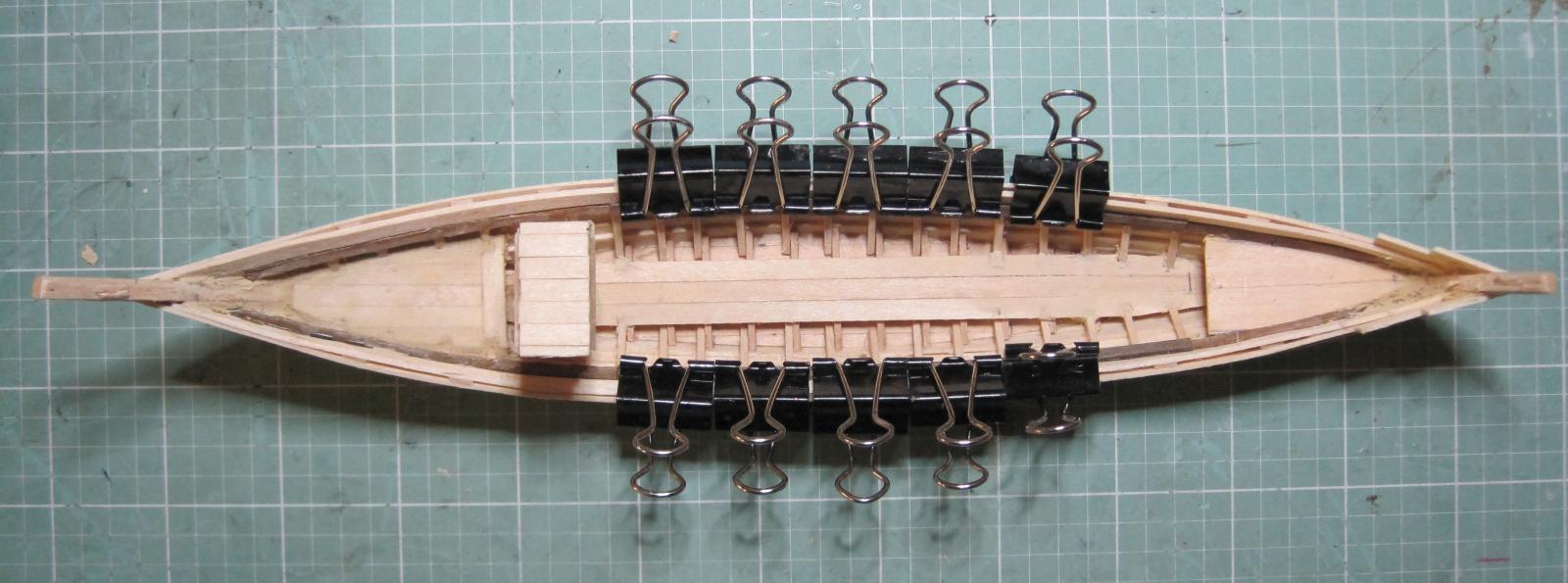
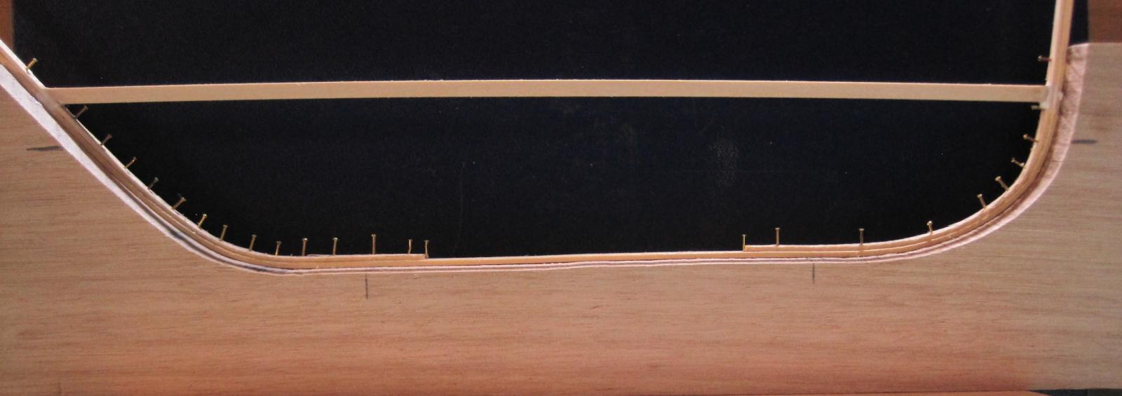
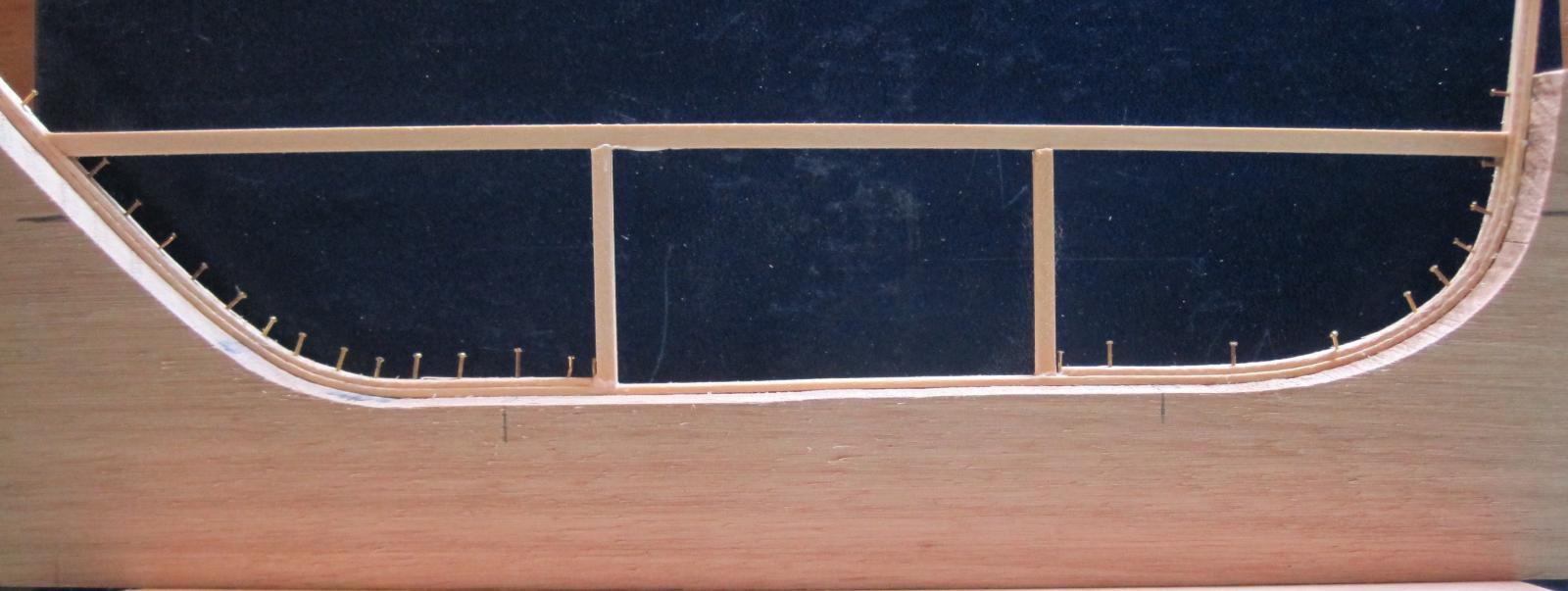
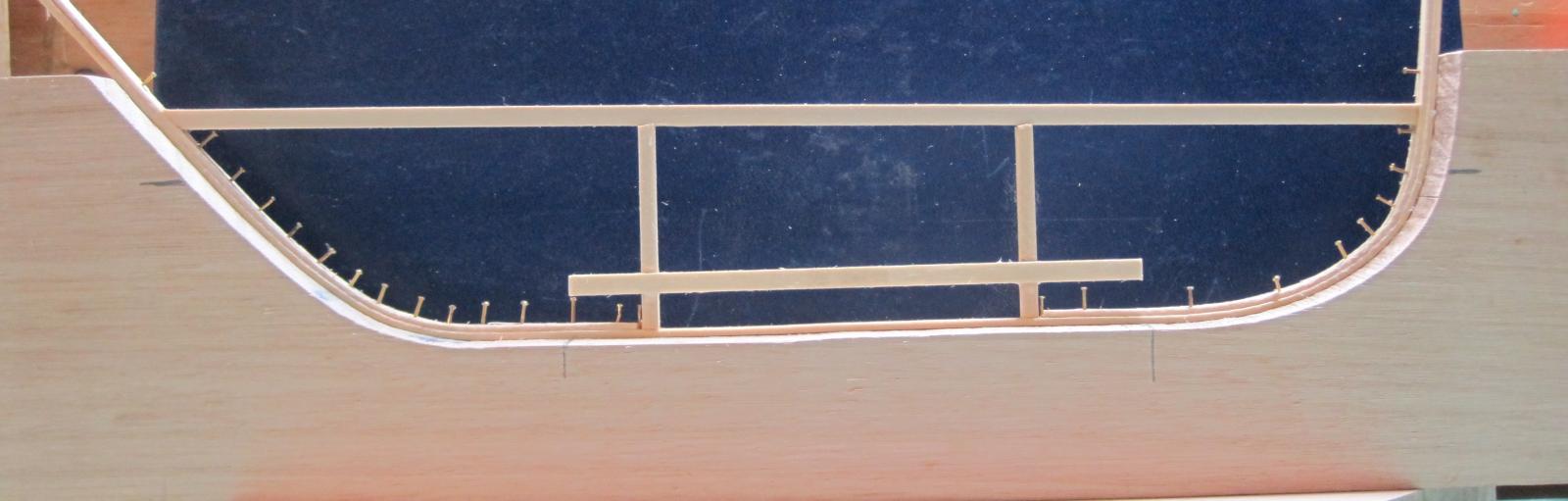
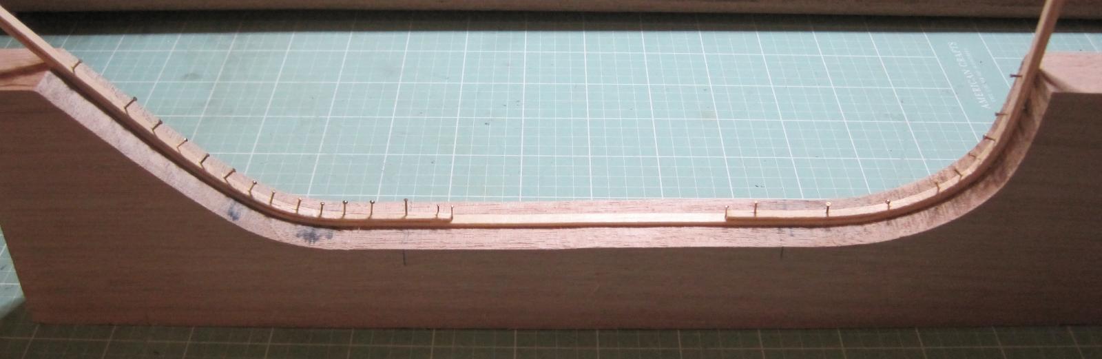
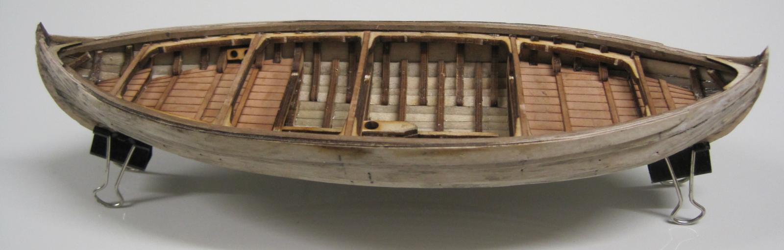
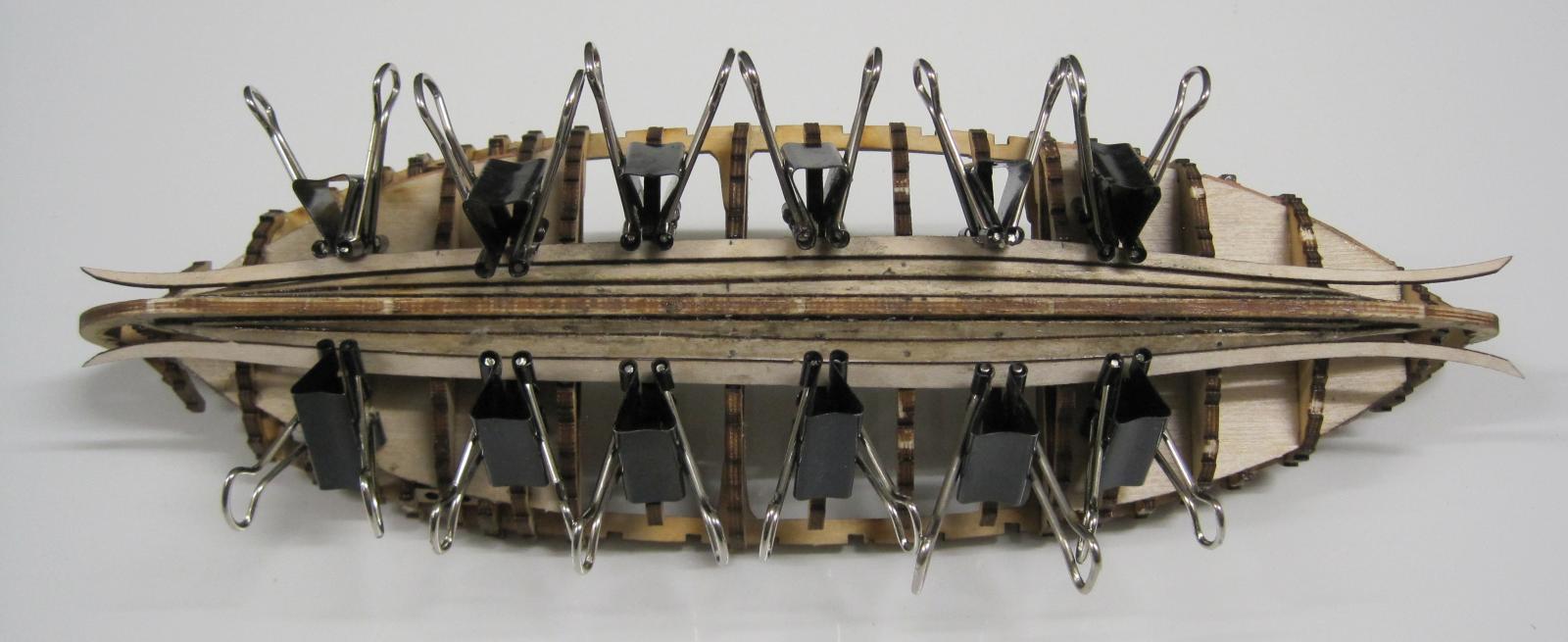
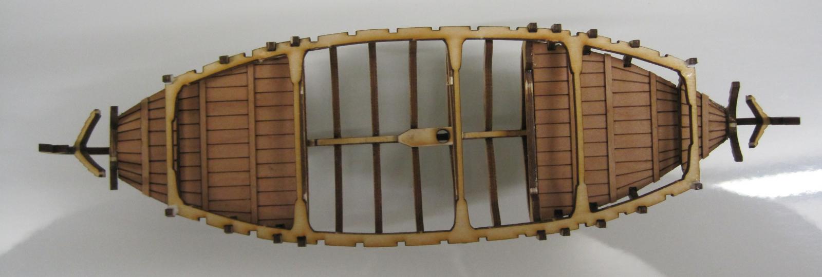
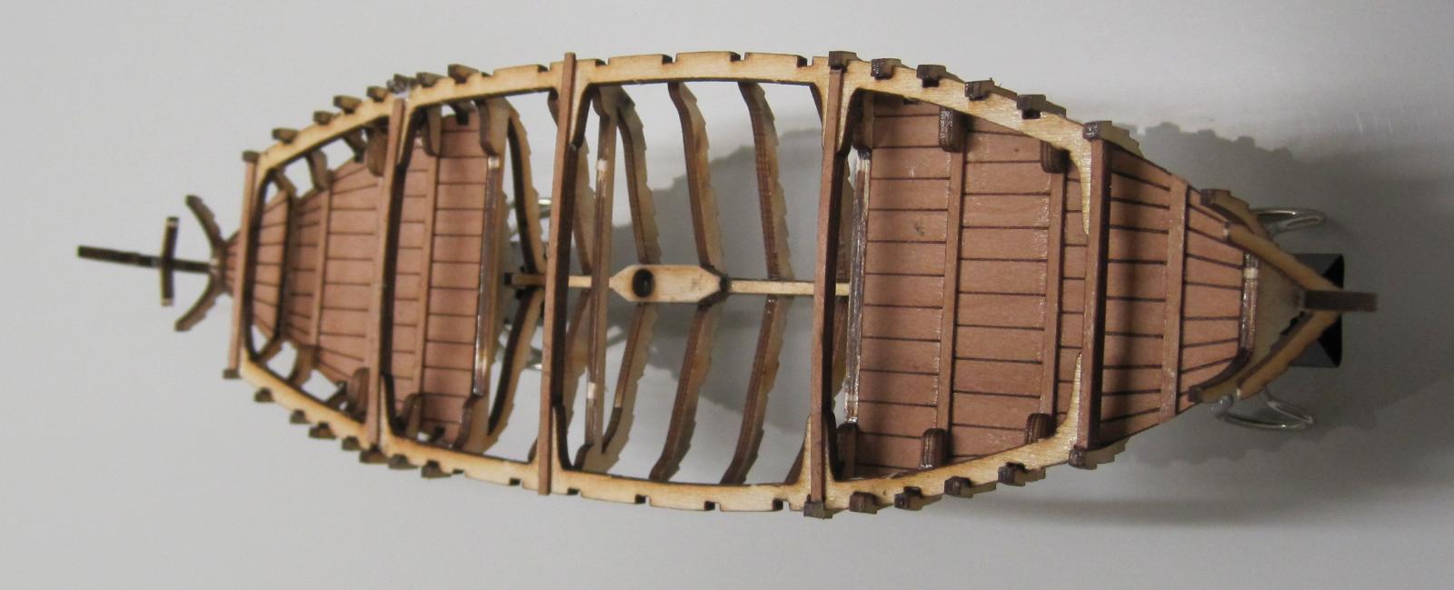
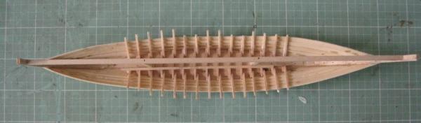
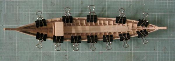
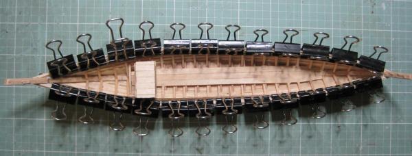
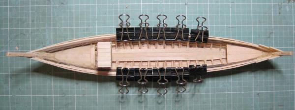
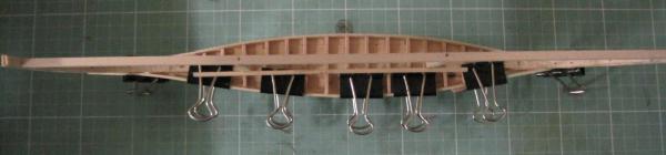
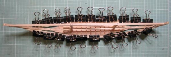
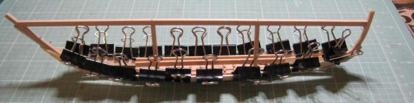
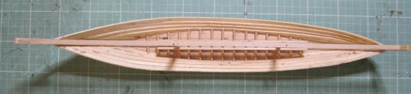
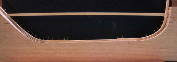
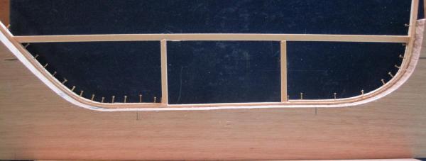
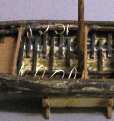
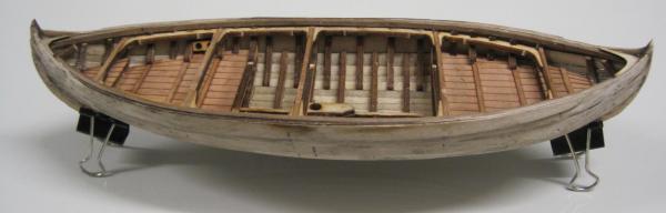
This cold weather has kept me inside so lots of small projects being done. The Rabelo is progressing nicely and the following show where it is at now. The next task was to fit the bottom braces and side frames. You will notice that the frames extend above the previous planking. This is because they have both internal and external beams attatched to them and then some side trim. The following three photos are of the beams and trim being attached. Don't you just love those little pegs. Very hand for a model that is only 230mm long. Now it is time to install the front and rear decking and the central walkway. There is a framework that holds the port barrels. The first pieces are the supports that run along the inside of the hull above the previously installed beams. At this point, I thought it would be best to start painting the inside before fitting the barrel framework. Some of the Rabelos have intricate paint jobs and I will be attempting to copy the paint work on an original Ferreira Port House Barco Rabelo. As the paint dries, I am off to continue work on my next Diddley Bow.


-
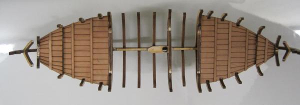
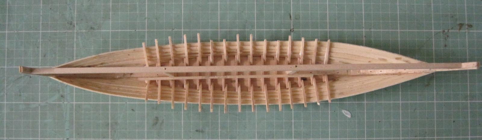
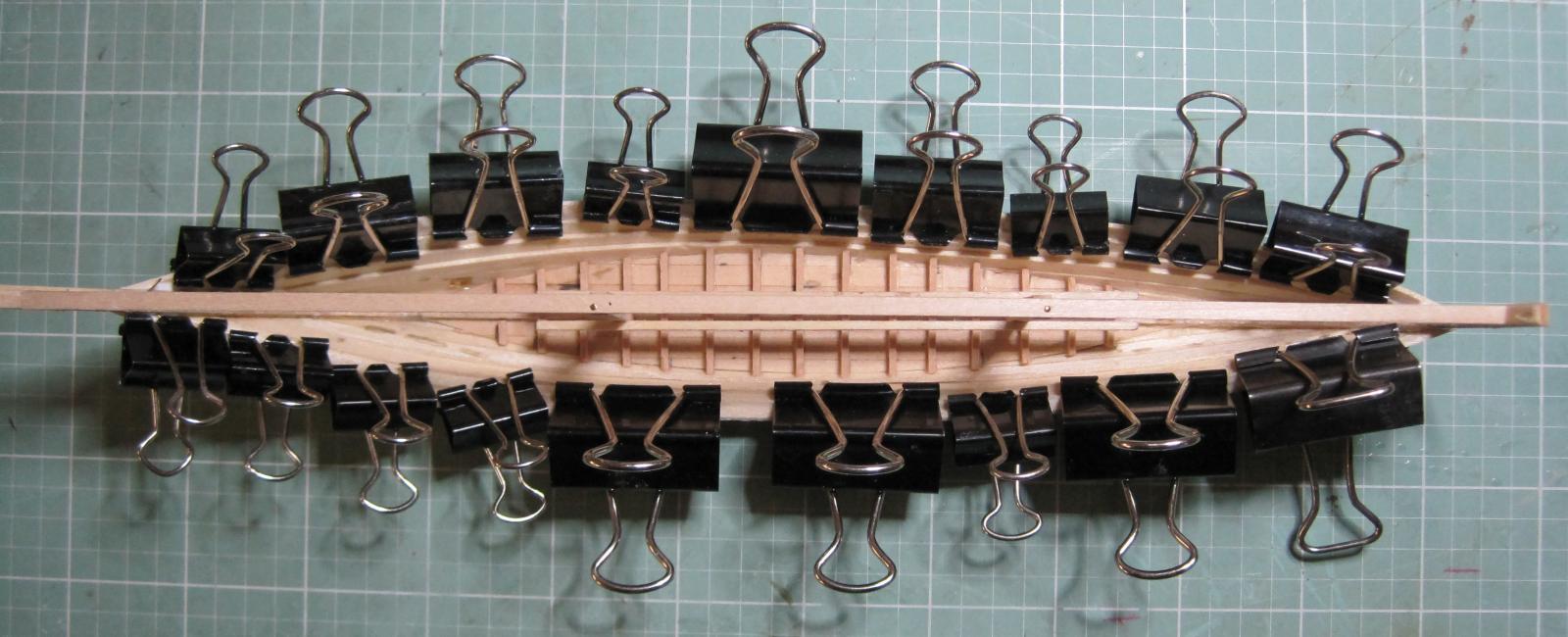
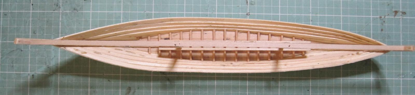
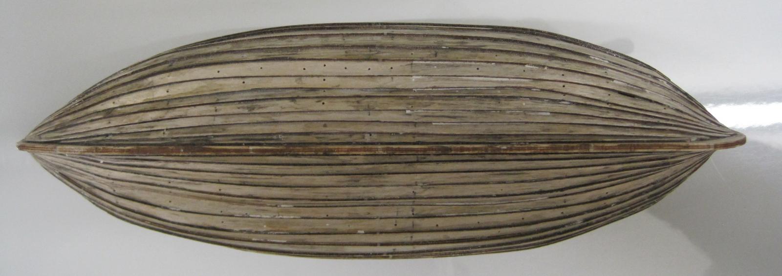
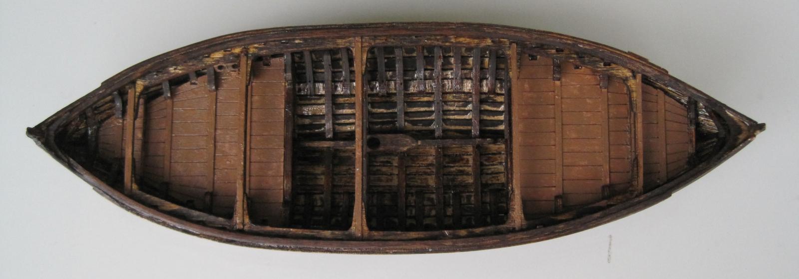
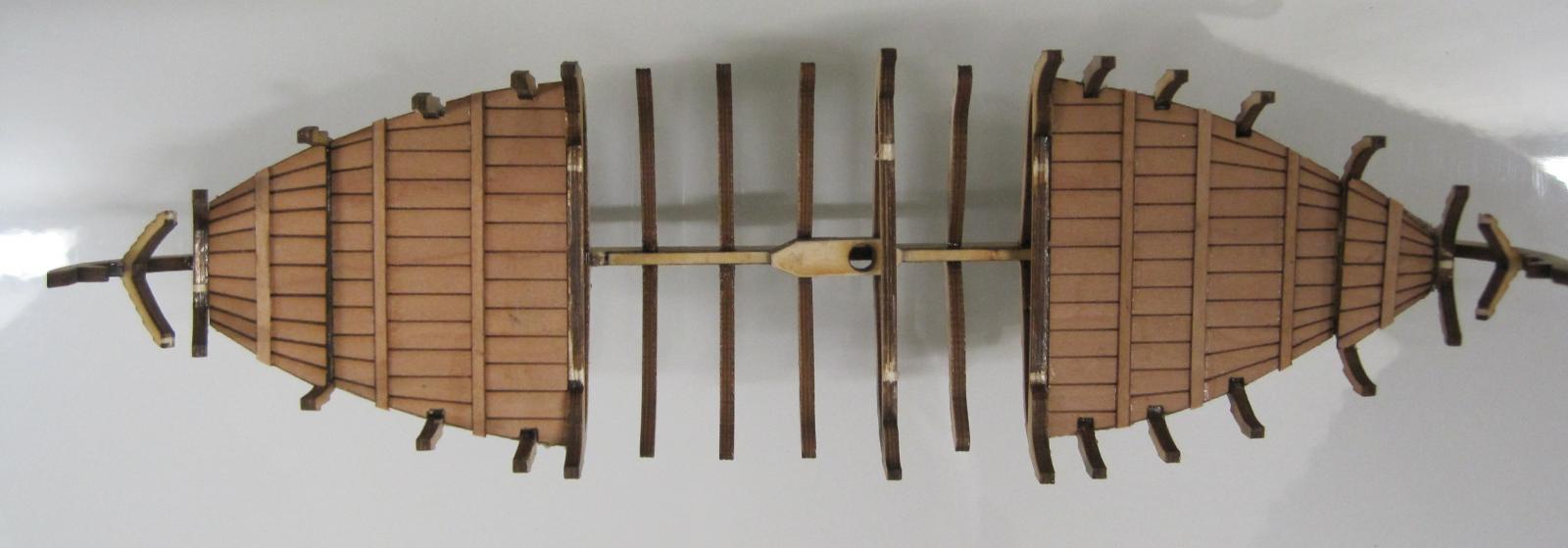
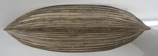
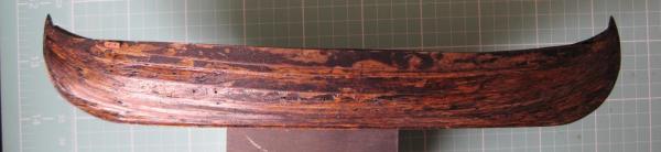
Finally got around to doing some more on the Rabelo. The first step was to install the cross braces on the sagro. Now came the fun of adding the planking. And that completes the build of the clinker hull. The next job will be to install the frames. It will be fun cutting them to size to fit.


-
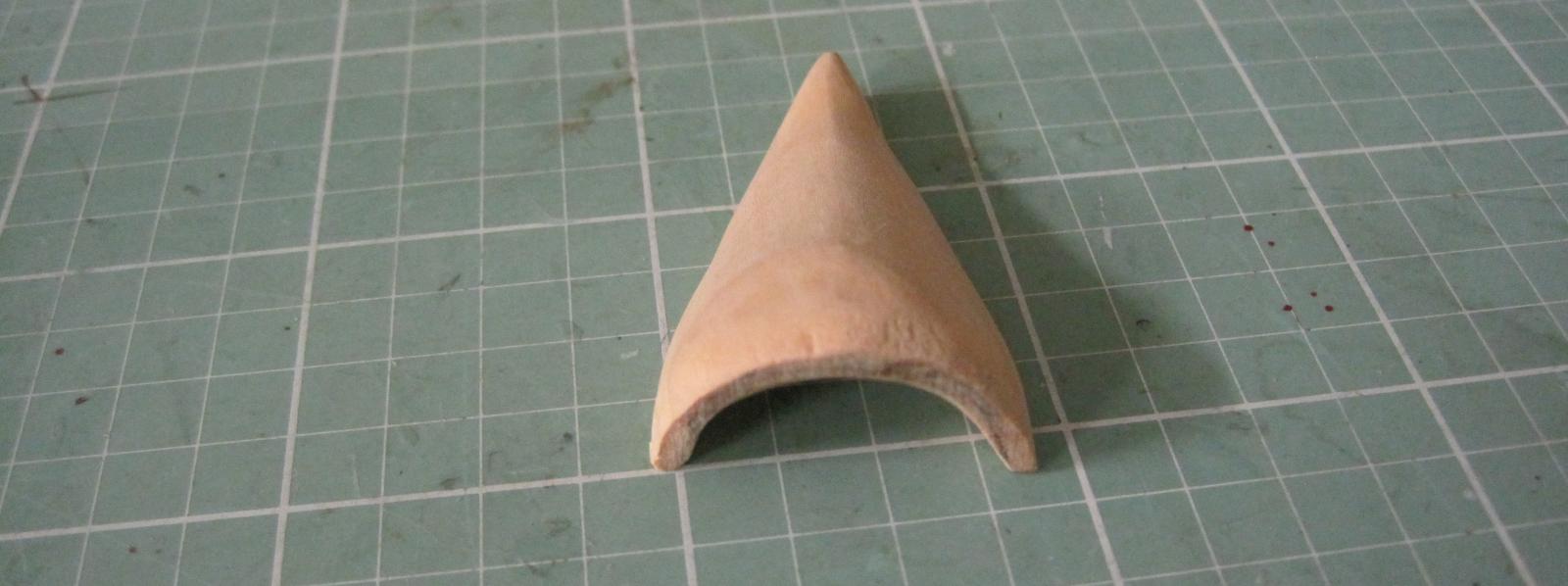
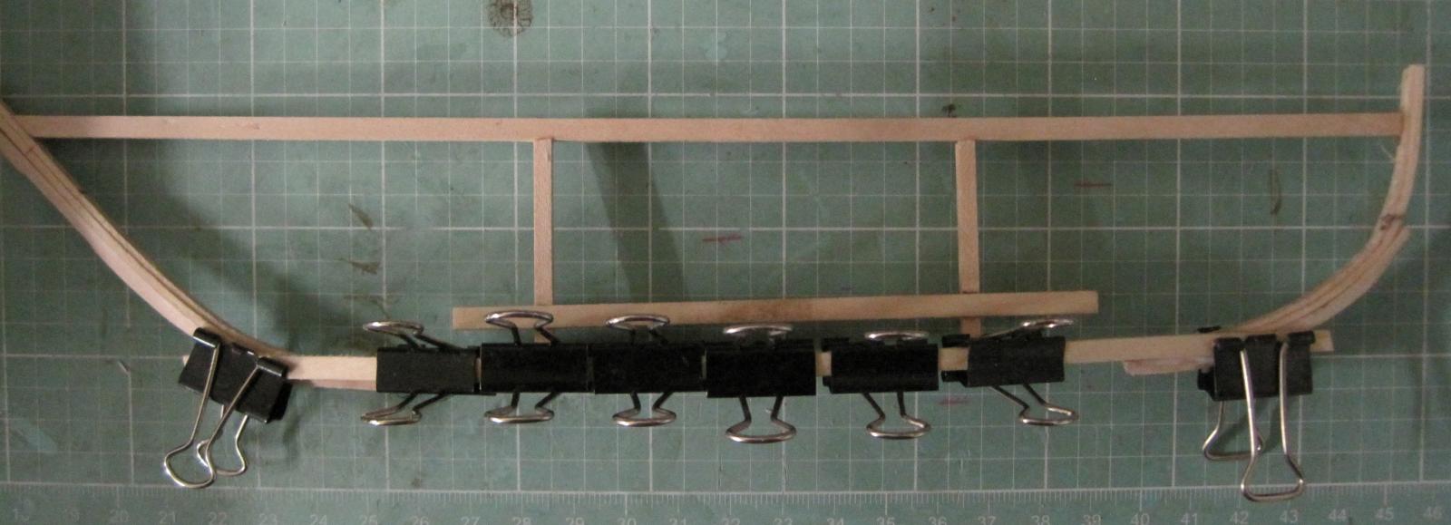
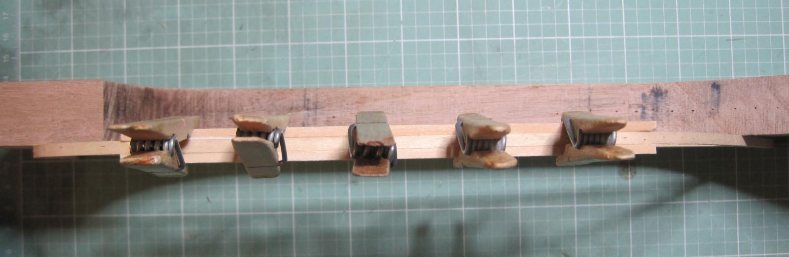
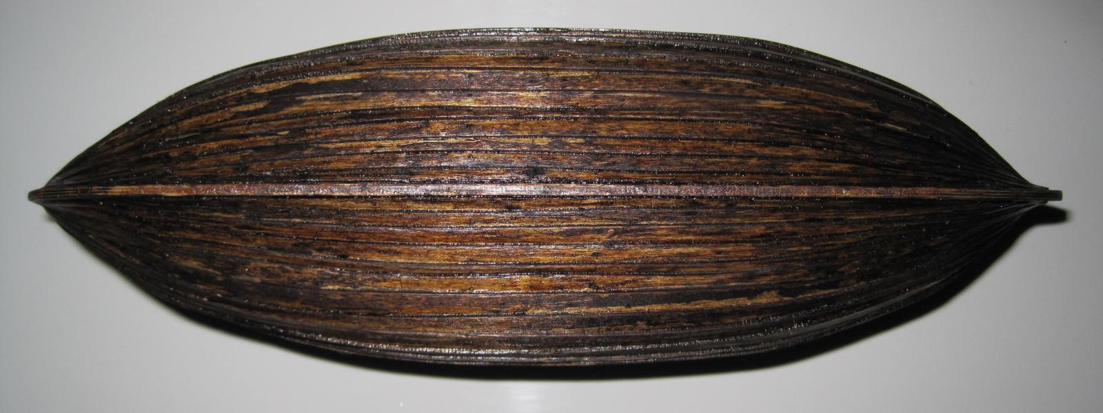
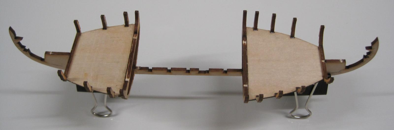
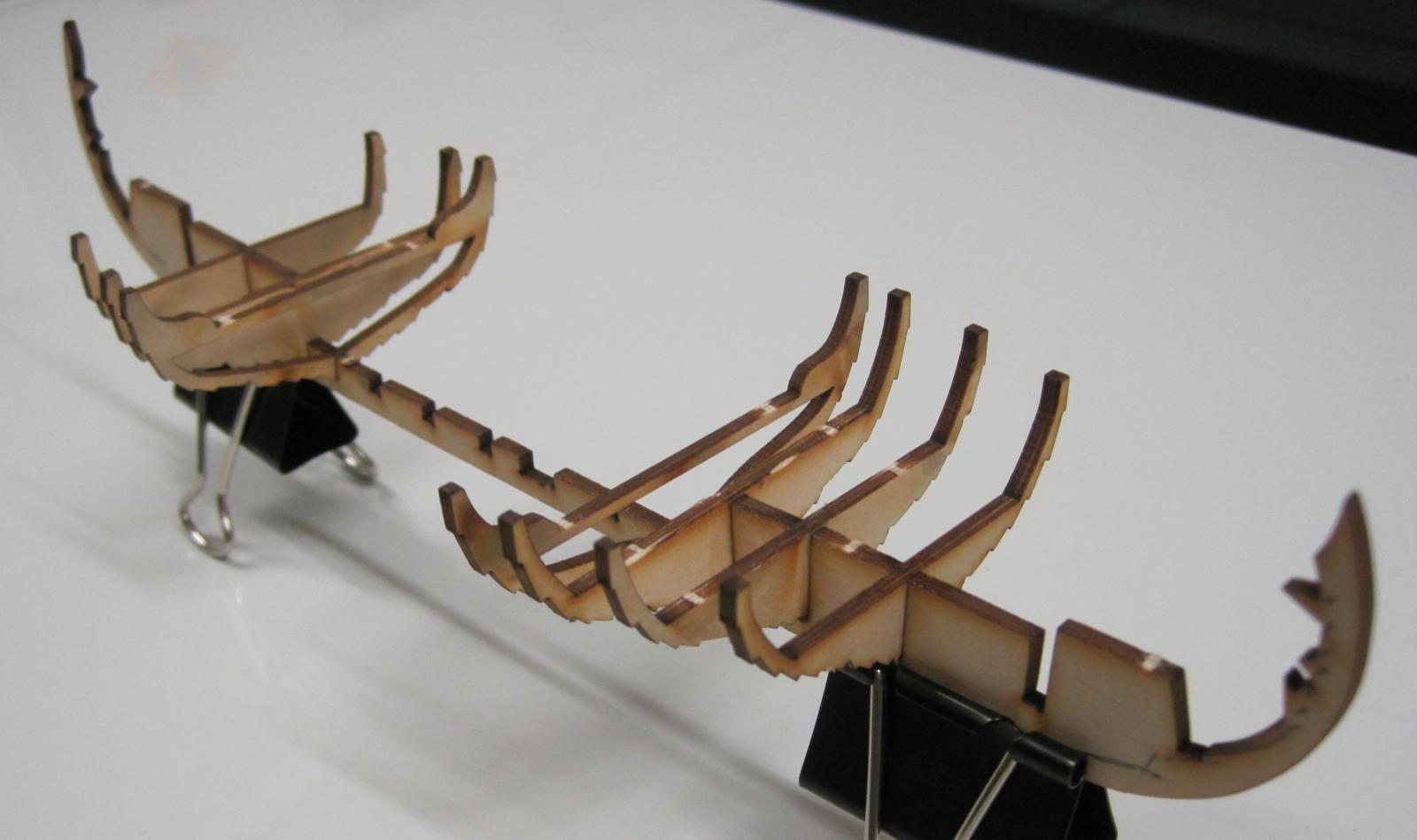
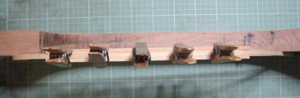
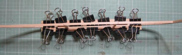
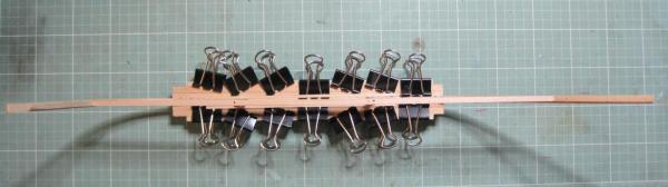
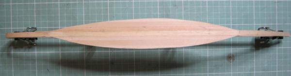
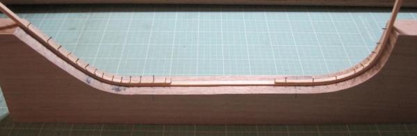
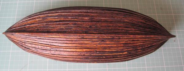
I have now completed building the Sagro. The following photos show the planks being attached and then the final shaping. On the old Rabelos, before any side planking was done, the Sagro was shaped by placing the two ends on raised posts/planks and then placing weights on the centre. The plan I am using has a straight Sagro. The next piece of work is to attach a triangular piece of wood to the full length of the bow and stern which will provide additional support for attaching the side planks. This is not normally done but due to the small scale of this boat the additional wood will certainly help.
-
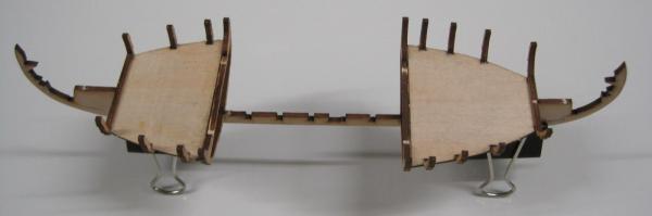
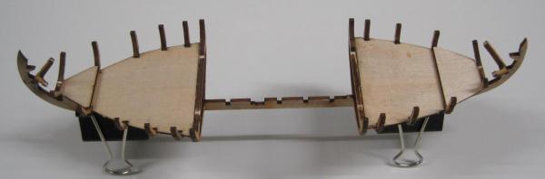
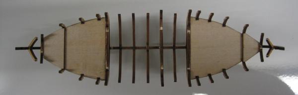
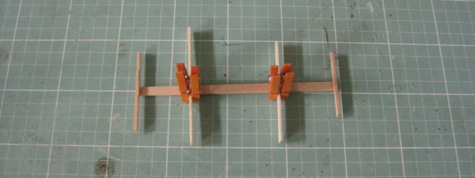
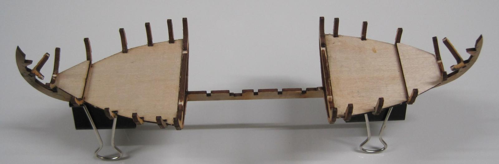
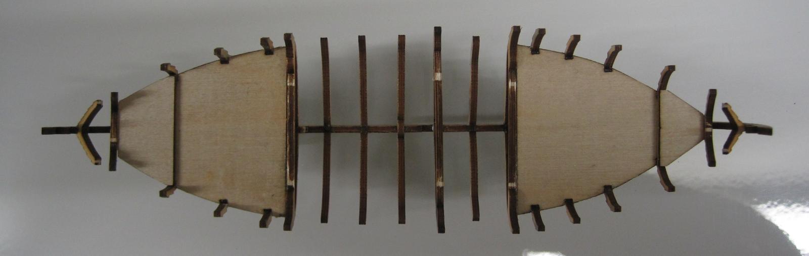
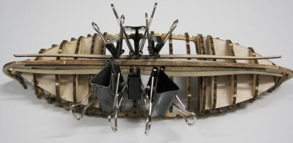
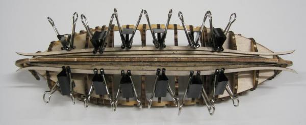
Step 3 - Installing temporary reference frame. As the frames are only inserted once the hull planks have been installed, I have decided to install a temporary framework from which I can take measurements whilst installing each plank. This hopefully will ensure I have the planks at equal distance from the center line at each point a frame is to be inserted. Nothing worse than having one side laying out/in more than the other.

-
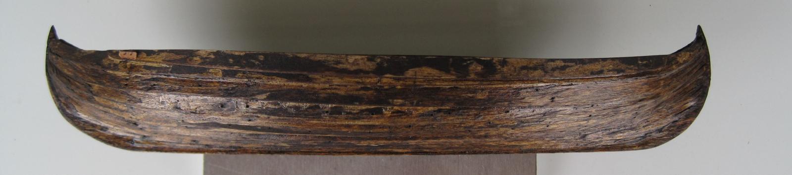
Step 2. Installing the Roda Proa (Bow brace) and Roda Popa (Stern brace)
-
Hi Tadeusz Thank you for the great photos. The Rabelo is a very interesting boat and I am always very keen to see new photos as I cannot find anything that details exactly how the rigging is installed. I have a good idea but it would be fantastic to know exactly how it is done. I am currently talking to some people from the wineries in Portugal who are looking for me so fingers crossed that by the time I get to the rigging I have all the information I need. Daryl
-
Hi wefalck Thank you for the link. I have just had a quick read. I am trying to find as much information as possible on the Barco Rabelo and the Douro so I will add that link to my collection. Daryl
-
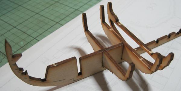
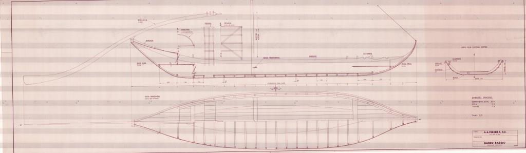
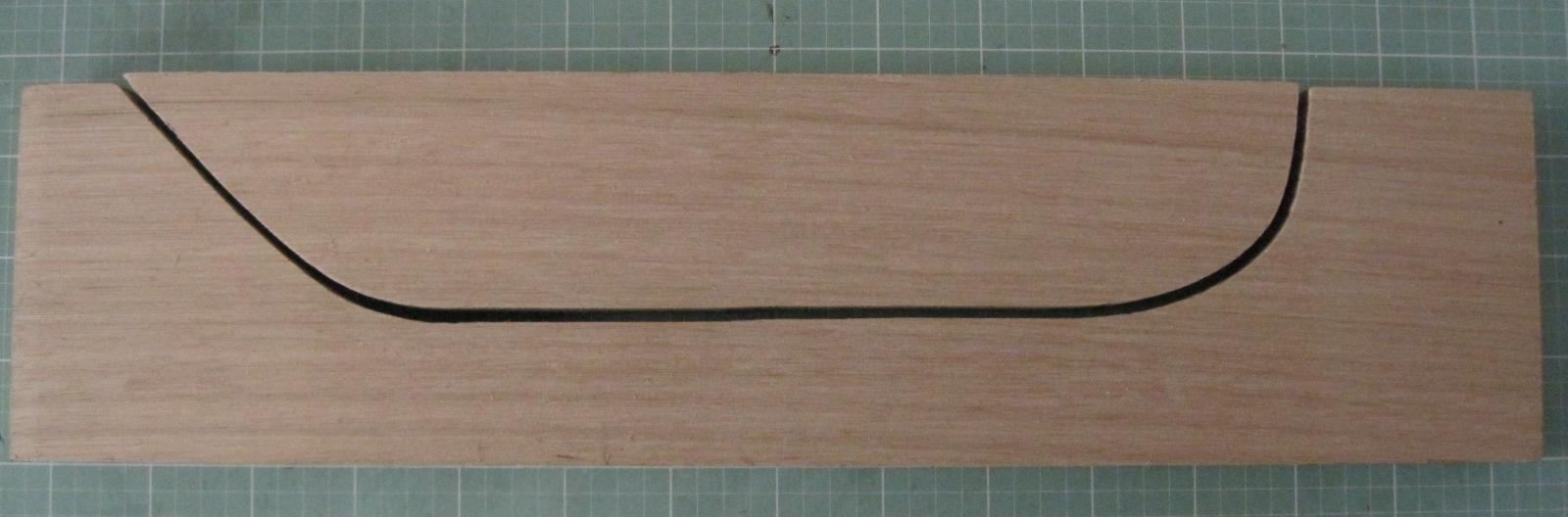
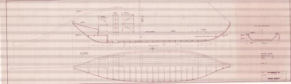
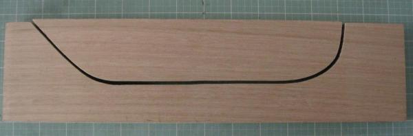
Step 1 - making jig. The first photo is of the plans. When I originally downloaded them they were 50Mb and have since been cut down. The next photo is the start of the build. It is a jig I have made to shape what would normally be called a keel. As the Rabelo is flat bottomed it does not have a keel. It has a flat bottom which is the shape of a surf board with a point at each end, which was called the "Sagro". The older Rabelos then had an extended stem and stern post (Oucas) attatched to the Sagro. On my plans, the centre plank of the Sagro runs from the tip of the bow to the tip of the stern and then there are two internal "strengtheners" called the "Roda Popa" (Stern brace) and "Roda Proa" (Bow brace) used to help keep the shape. Tomorrow I am off to Float a Boat to get my strips of wood to commence the build. As this is a 1:80 scale and the overall length (minus the huge steering oar) will only be 250mm, I am thinking of also going to the optometrist to get the eyes checked. :-)
-
Background History. The Barco Rabelo (Rabelo boat) is a flat bottom boat first built in the 9th century to navigate the rapids of the Douro River in Portugal, carrying up to 100 barrels of port from the Port Houses to the coast as the river was then the only means of accessing the wineries. It had a crew of 12 men and was noted for its long steering oar which was managed from a raised platform above the port barrels. In 1887, a railway line was built along the banks of the Duoro and this started the demise of the Rabelo. Eventually roads were also built and the last official trip of a Rabelo is thought to have taken place in 1964. To celebrate the history of the Rabelo, a race is held annually on St John's day (24th June) where each Port House enters its own Rabelo. My build. Thanks to Ryan Opaz from Vrazon, I was fortunate to obtain a copy of plans drawn up for a Rabelo in May 1989 for the A.A.Ferreira, S.A. Port House in Vila Nova de Gaia. The plans were held in the Sogrape Vinhos S.A. archives and I am very grateful to them for providing me with the plans. These are the only official plans of a Rabelo that I have been able to find and they do differ in some areas as to how a Rabelo was originally built.
-
Hi I have just tried to start a new scratch log and have ran into a problem when I go to copy MSword text onto the page and attach a photo. The text and the file name do not appear on the page like they used to. in my last build log. If I click on the preview button I can see the photo but not the copied text. I feel it must be a setting but cannot find anything. Daryl
-
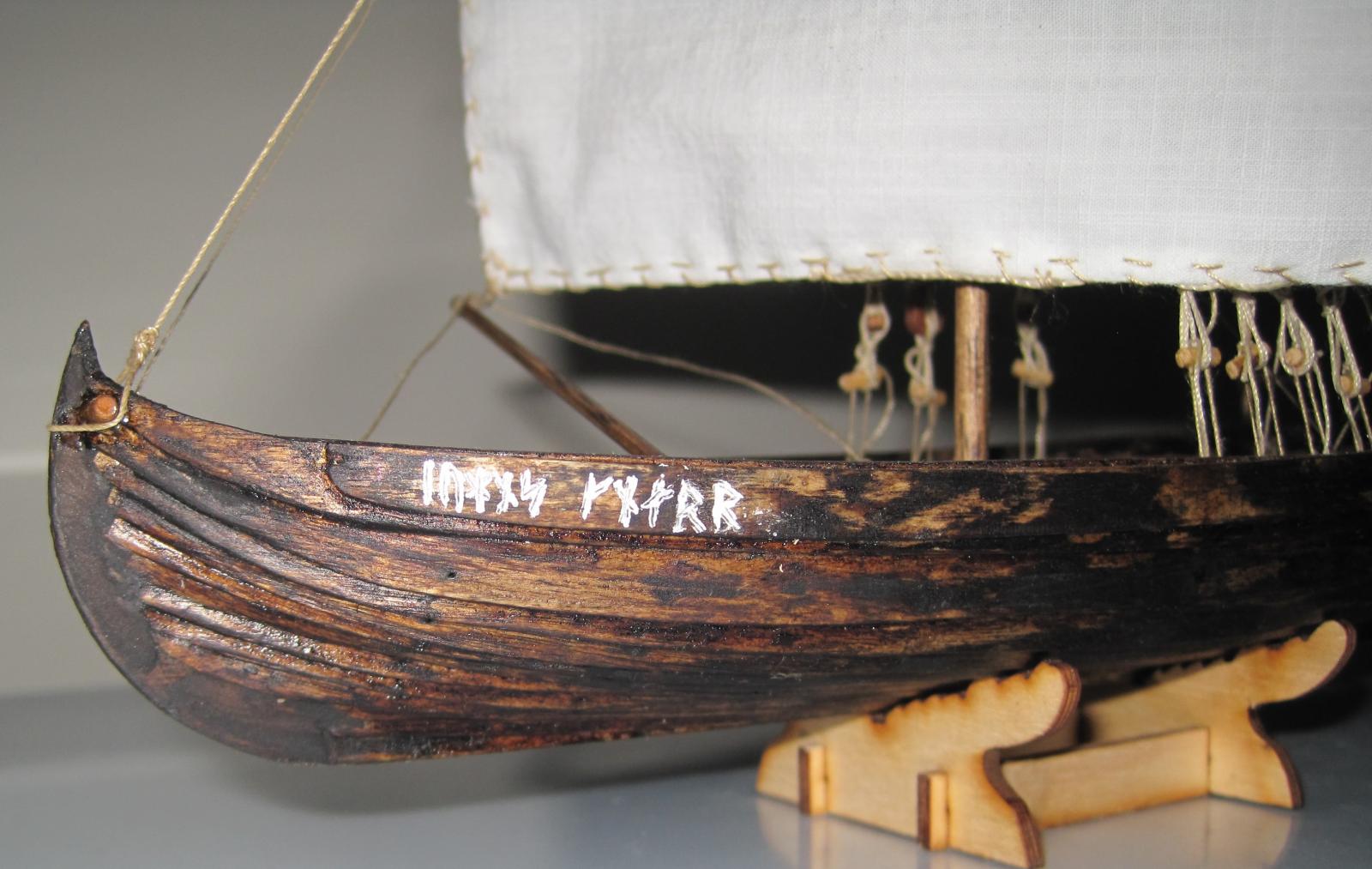
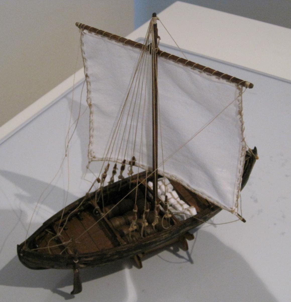
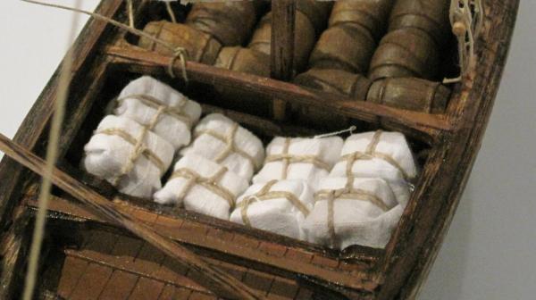
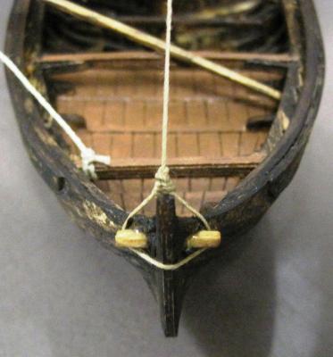
I could not wait. I was so close to finishing it so I got on with it. Attaching the rudder to the hull is interesting. The rope starts from outside (knotted end), goes through the hull, comes out side and then back inside and ties off. Or that is how I see it happenign. Here is how it looks. The barrels did not want to lay straight by themselves, so I stuck two together and hey presto, everything went well. Wrapping the bales was fun, especially as my fingers are not on the small side. And then it was finished. This has been a fun build. Not sure if I will do a 1:72 scale again, but you never know. John is the name of the gentleman who I have built it for. We are going to name it John's Knarr. It will be painted on the bow in the "Younger Futhork” (Long Branch) Runic alphabet. Younger Futhork or "Normal Runes" gradually evolved Elder Futhark over a period of many years and stabilized by about 800 A.D., the beginning of the Viking Age. It was the main alphabet in Norway, Sweden and Denmark throughout the Viking Age. John's Knarr translates to: I hope you have enjoyed watching this build as much as I have enjoyed doing it. I will be back sometime in the next 2 - 3 months with my next build once I have finished the other 3 projects I currently have underway. 1 - Restoring a 1901 Singer treadle Sewing machine, 2 - building a Cigar box ukulele and 3 - building a rocking horse for a new great nephew.

-
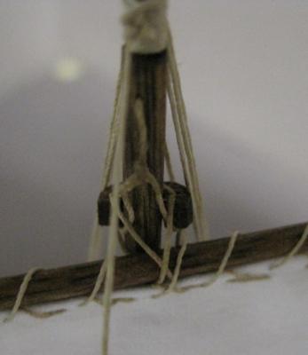
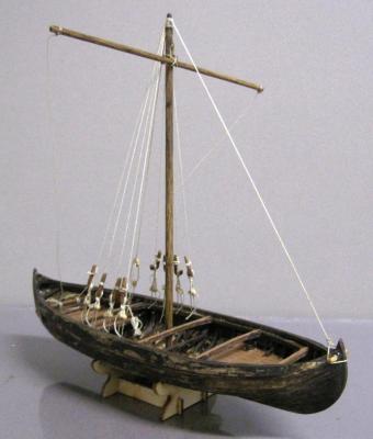
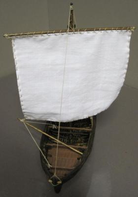
Rigging time. I found a few things that I was not happy with and therefore made changes to. The first one was how the shrouds were attatched to hull. In the instructions, they asked that you tied a loop through a hole in the inner frame (see follwing photo) and then linked the shroud to it using the shroud pins. If you did this, then there was no way in which you could tighten/loosen the shrouds. Searching on the internet I found another option which I decided to follow. It is shown in the next photo. The next photo shows the mast with its shrouds. The next thing I changed was how the forestay was attached to the bow. The instructions ask you to tie the forestay through a hole in the bow. Whilst researching I found that there was a "pin" inserted through the bow which the forestay was tied around, so I decided to do that as is shown in the following photos. The last thing I changed was the Parrel. There is evidence that they used a wooden parrel so I made one up and used that insted of tying rope around the mast and spar. The following photos show the sail, sail bar and some of the sail ropes I hope to finish the rigging in the next week and then make up the cargo and that will be it.
-
Thanks Keith I will certainly try to get there. Daryl
-
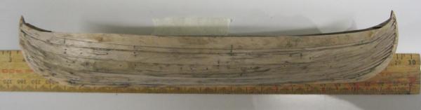
I have now finished planking the hull but found another problem which is more lack of detail in the instructions rather than a problem with the model. As I mentioned earlier, before starting the planking, you have to instll the "Inner Frame". It sits some distance below the tops of the main frames. The instructions do not tell you how far below so I took an estimated guess from looking at the drawings. My suggestion would be to not glue it in place but to pin it so that you can complete the planking and then relocate the Inner Fram so that it fits more correctly. ie the gap between the top of the Inner Frame and the side beams is uniform. It would also need you to not glue the sub-frames into the Inner Frame but pin them as well. A bit of extra work but I think the end result would warrant it. All planks attached - Bottom and side views. How it looked before painting. You can see the uneven space I referred to between the Inner frame and the side beam. The internal hull was painted with Pine tar and the fore and aft decking with some model boat "wood brown" paint. The external hull was painted with Pine tar. The following photos show how the color changes in different light. I am now working on the Rudder oar. Once I have finished that, I will be having lots of fun using heaps of 4mm lengths of 0.5mm black fibre optic as replacements for the wrought iron rivits used on the original Knarrs. The Dremel is about to get a serious work out. Hopefully I will start on the rigging in two weeks time.


-
Hi Keith I am not aware of the club meet. Can you please give me some details. Daryl
-
At this point, I found that the planking contour lines I drew on the keel as per the first step in the instructions, no longer match up with the rebates in each frame. I finally found out that the drawings in the plans show there are 11 planks on the stern and 10 on the bow. I immediately contacted Daniel at Dusek and pointed this out to him. Within a couple of days, Daniel had sent me a new drawing showing the correct layout of the planking. Attached is a the file Daniel sent me in case someone has found the same problem. revised knarr72-plan.pdf I have found that the response from Dusek has always been quick and fantastic. The only other problem I have found with the planking is that I feel the planks are about 1-2mm short each end. I have been having difficulty in clamping them when glueing and a bit extra timber would make the clamping much easier and it could easily be trimmed off once the glue has set. I will pass this on to Daniel later.
-
And now it is time to start the planking. Each frame is cut so that you have a rebate to fit each plank in, thereby making the alignment of the planking a lot simpler. What make the little grey cells work overtime (apologies to Hercule Poirot) is making sure you have the planks centered correctly before gluing them. The contour lines I mentioned in the beginning now become very important. So far, I have found the rebates to have been very well cut as the odd shape of the planks seem to fit into them very nicely. I am not concerned if the spacing of the planks is not perfect as I am assuming they were not 100% perfect on the original knarrs all those years ago. The next photo shows the first planks installed each side of the keel and the second row being aligned before fixing. The next photo shows the 1st & 2nd rows attached and the 3rd row being aligned. It only took me two rows to agree with their instruction comments regarding gluing the planks from the middle before doing the ends. I am fixing the planks to the middle 7 frames and letting it set completely before doing the ends. As there is limited space to use clamps, I have been using very very small brass nails to hold the planks in place while the glue dries and then removing them later.
-
Q. What does one do when it is 40 degrees C outside? A. Go inside, switch on the A/C and start building a new model. A very small one (1:72) so the rigging is going to be fun when I get to it. And I have. First off, I must say that I really like the laser cut ply that is used for this model. Very strong, and the laser cuts are spot on. I found that when putting the parts together, I really did not require any glue most of the time. The fits were tight and perfect. As I mentioned earlier, I now know that the drawings are only "simplified". ie. Not perfect. But, so far, that is not causing me any problems. The first step is to use the "to scale" drawing to mark on the keel the contour lines of the planking. This helps in aligning them later on. Having done that, I then started installing the frames. The frames are installed in groups. The first set cater for the main decking. Now the support for the deck planking is installed on these frames. Now comes the next section of framing which is for the bow and stern, and their associated small decks. The remainder of the main frames are now installed. The Mast foot is now assembled and installed followed by the deck planking for all 4 decks. Transverse strips are also installed across the deck planks. All the installed frames are now held together in place by the installation of the Inner frame. In the drawings, the Inner frame is located a distance below the top of the frames. There is nothing to tell you what the distance should be. If you do not glue this immediately (the fit is tight so you will not have a problem with it falling out) you can go to the next step where you have to install small frames that sit on top of the transverse strips and fit into cut aways in the Inner frame. The last set of frames are small deck/secondary frames spaced out between the main frames. I glued these in and once they were dry, fitted the Inner frame. Everything seems to be in line from stem to stern so I am looking forward to starting the hull planking in a day or so. And the weather has now changed and we are getting some rain. A fun weekend.