

schooner
-
Posts
641 -
Joined
-
Last visited
Content Type
Profiles
Forums
Gallery
Events
Posts posted by schooner
-
-
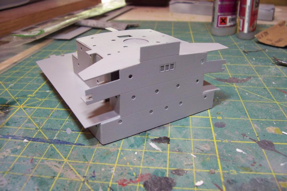
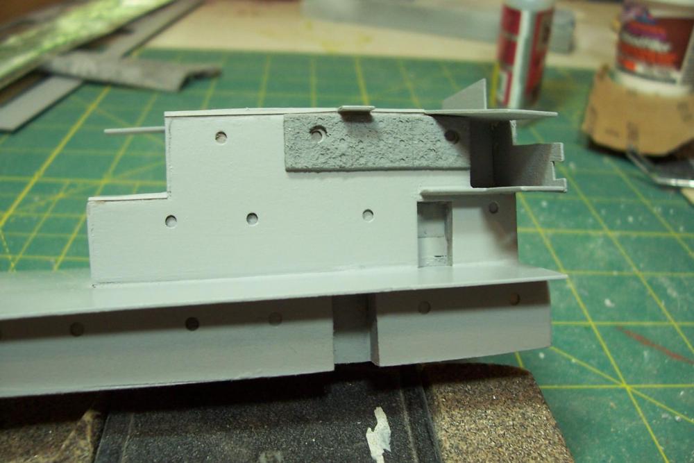
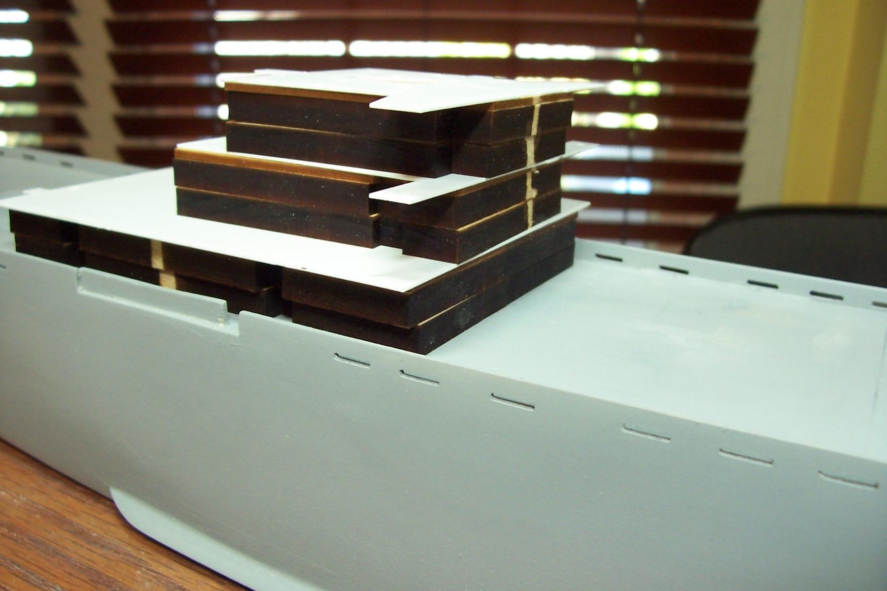
More of the Deckhouse
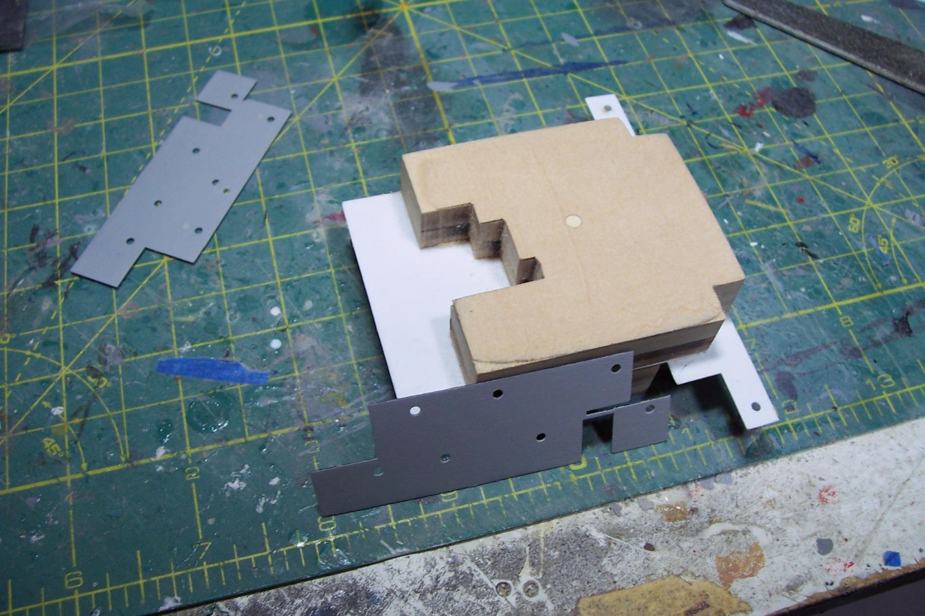
After glueing up the lifts it was time to add the thin laser cut facing pieces.

While test fitting them it quickly became apparent that the superstructure was taller than the facing pieces, as confirmed by the plans. The facing pieces are the correct height but the lifts are too tall, about 6mm total when all are stacked. After removing 1.5 - 2 mm from each level everything fit together.
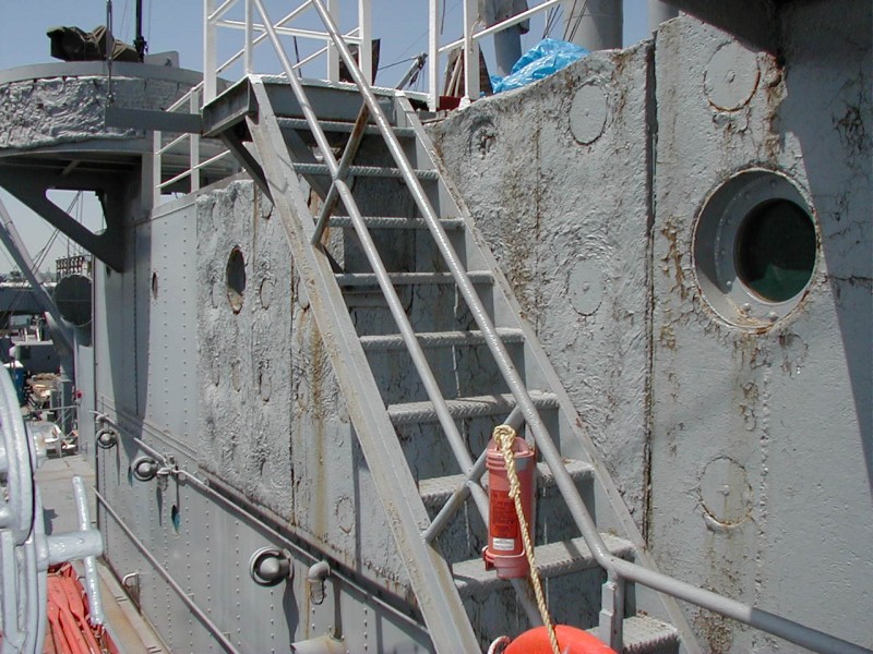
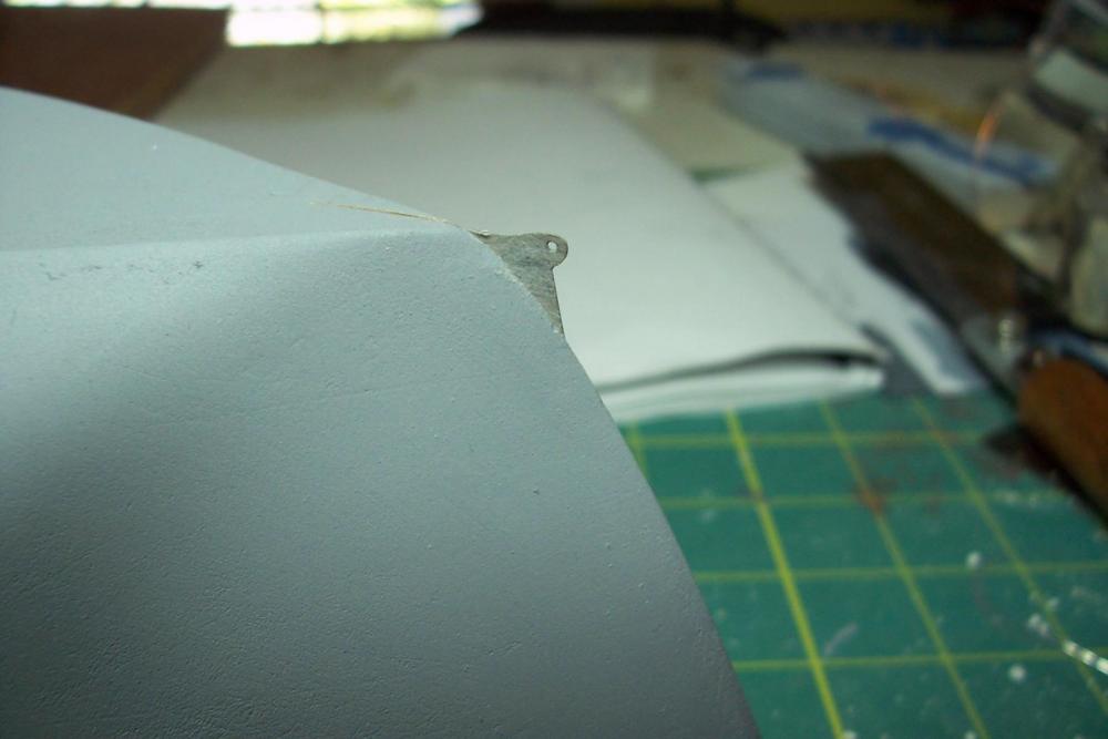
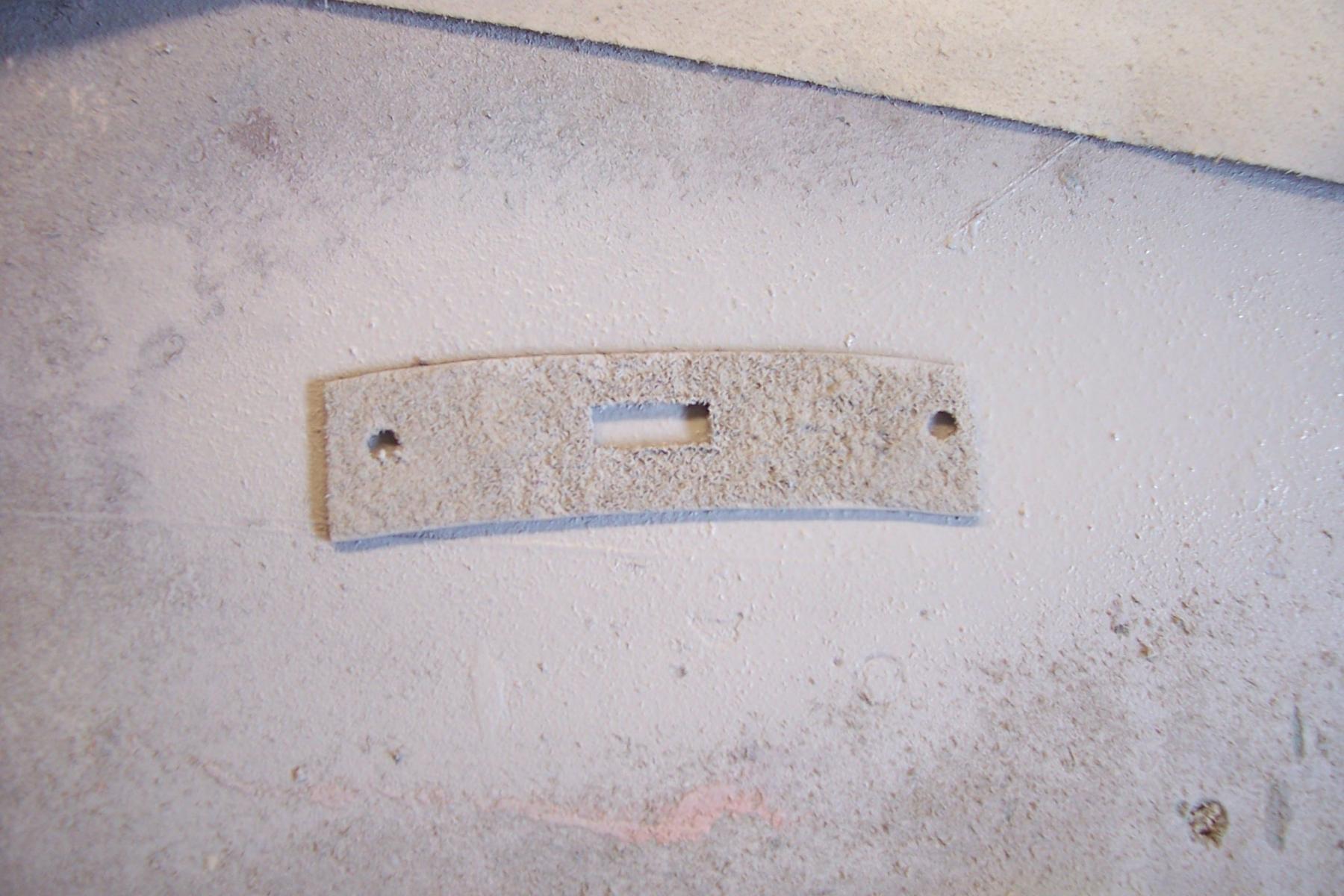
One of the odd features of the liberty ships was what looked to be concrete slabs around the pilot house and gun tubs like you can see here:
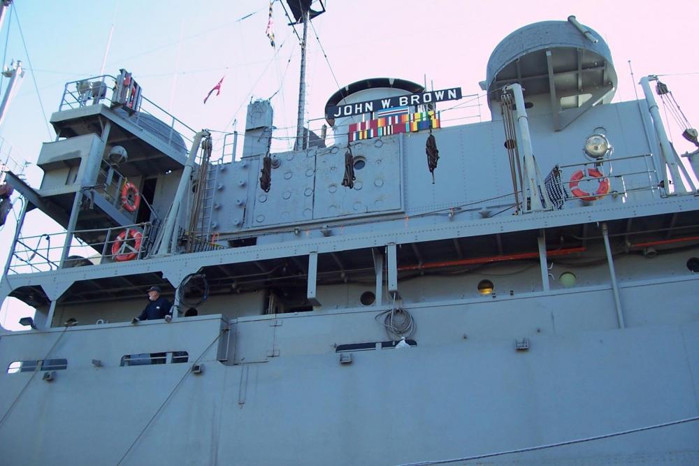
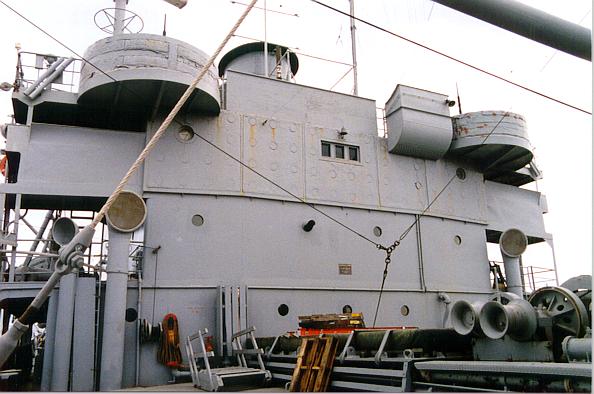
While visiting the SS John Brown I learned that it is not concrete but a British invention called Plastic Armour which is really just road paving material like asphalt. You can read about it here if you are interested:
https://en.wikipedia.org/wiki/Plastic_armour
As you can see in this pix it varied in its appearance even on the same ship; the nearest slab is smooth, the ones next to it rougher and the slabs protecting the gun tub in the background look like a sloppy job of adding foam insulation:
I decided to add it to my model. I cut thin wood to shape, drilled out the porthole lights larger than the portholes for the distinctive “stepped” look. I then sprayed them with primer and while it was still wet pressed them into some fine sawdust. A few more coats of spray primer reduced the fine granularity.
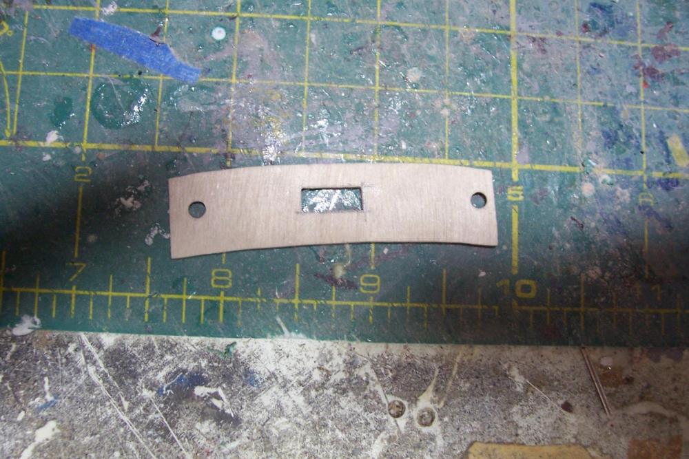
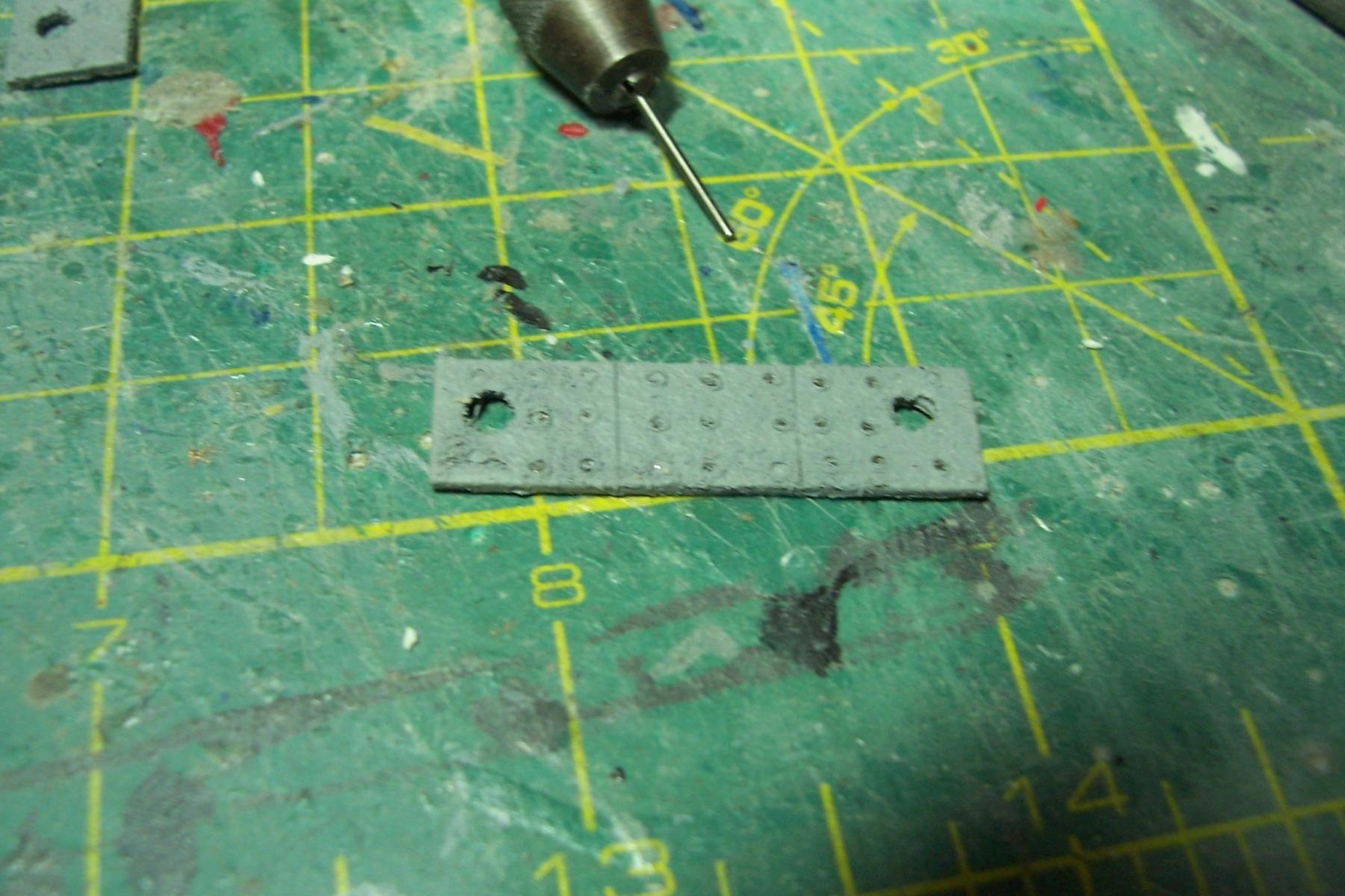
I then used the non-working end of a drill bit to press down to create the discs that worked like upholstery buttons to hold the armor in place:

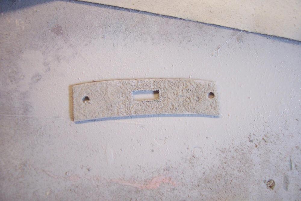
Here’s the finished product (Additional airbrush coats of the final color will reduce the granularity even more):
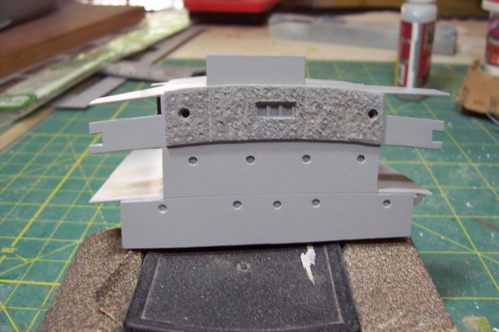
Next up will be adding the gun tubs and some more detailing that is easier done before the deckhouse is mounted on the hull.
- justsayrow, jct, omarcs and 17 others
-
 20
20
-
-
Thanks for the kind words Elijah and Greg,
It certainly weighs more than any plastic, resin, or even a POF or POB model, enough that I don't feel comfortable mounting it on pedestals since the leverage with that weight might loosen them up pretty quickly so I'll mount it on keel blocks (not sure how many yet).
Tim
-
Start of the Deckhouse
I’m going to depart from the kit’s build sequence a bit. The next step in the instructions is to install about 100 triangular bulwark braces around the outside of the main deck. I’m going to hold off on that until I’ve fabricated the deckhouses and crane houses because of the need to place sandpaper on the deck and then rub the house bottoms on it to get a good fit with the deck. Given the limited clearance between the bulwarks I’m sure I would end up breaking off a lot of the braces.
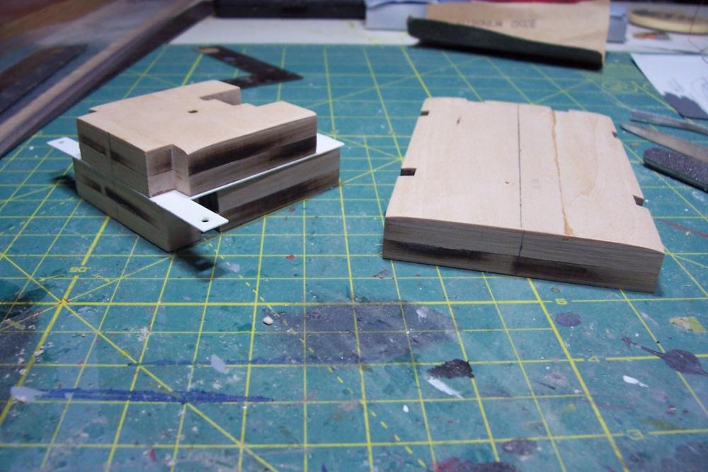
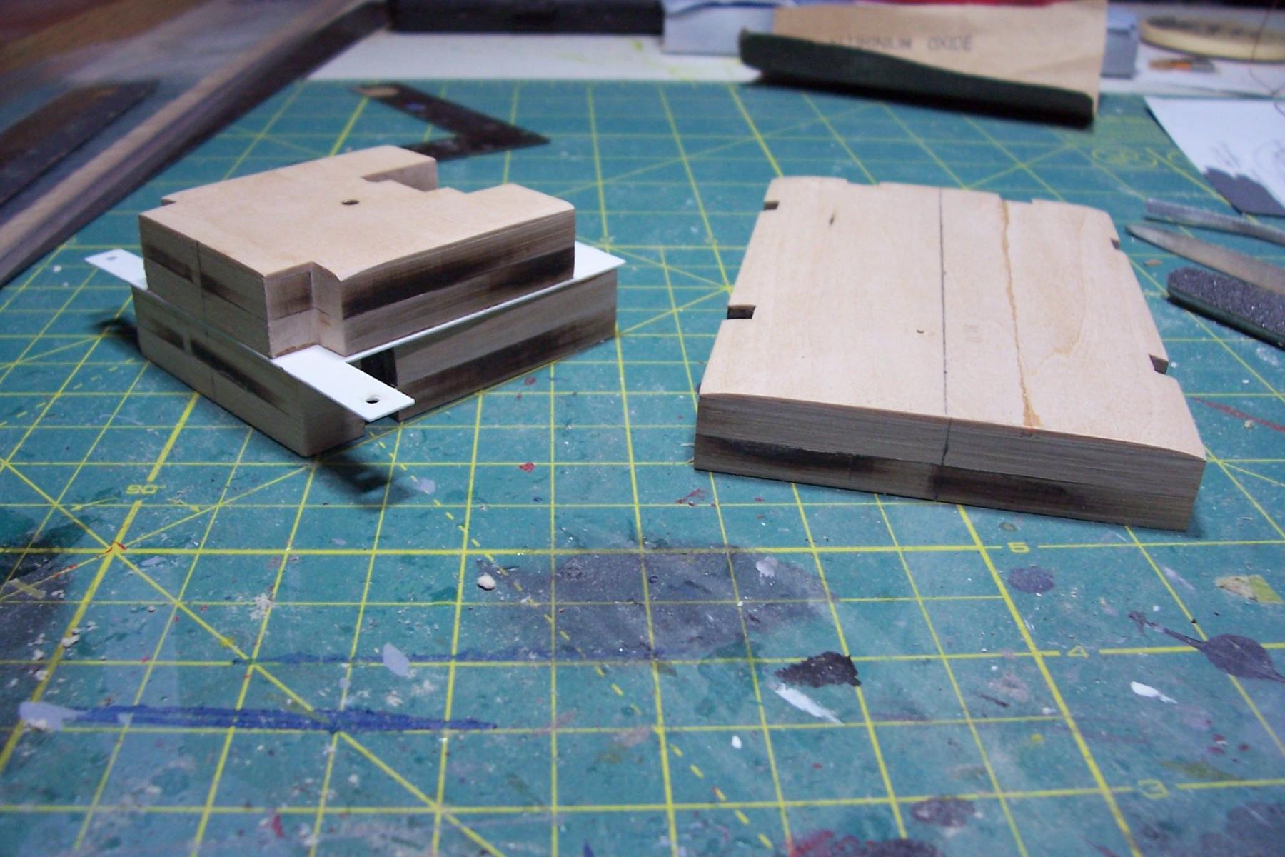
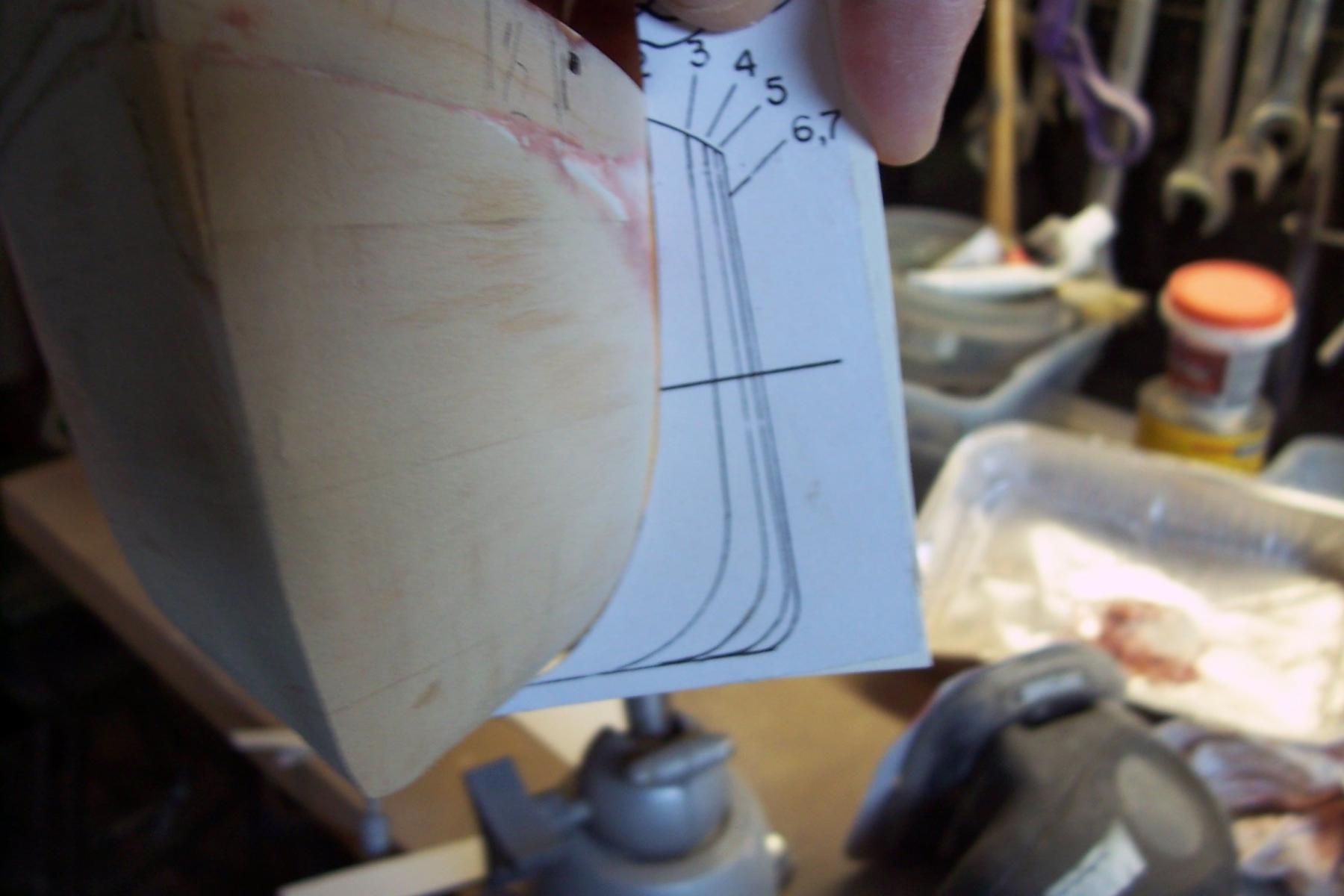
The Main Deckhouse is made of up 3 levels. Each level in turn is a stack of 3 laser cut wooden pieces and a thin plastic top deck. The bottom wood piece is a framework so that the amount of surface area that has to be sanded to match the deck underneath it is minimized. The top wood piece is a 1/16 inch sheet that is sanded to form a camber, its center staying 1/16 thick and the outer edges sanded to nothing. Here’s what 1 set looks like:
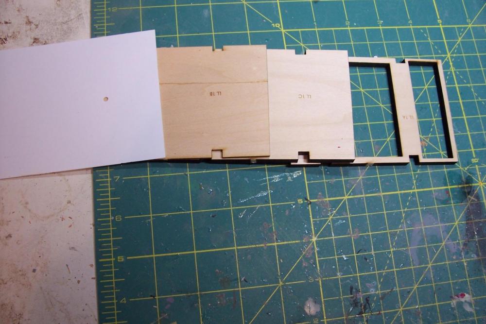
Here’s all 12 pieces dry fitted in a stack:

- Red, steamschooner, mtaylor and 8 others
-
11
-
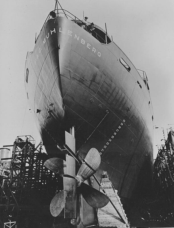
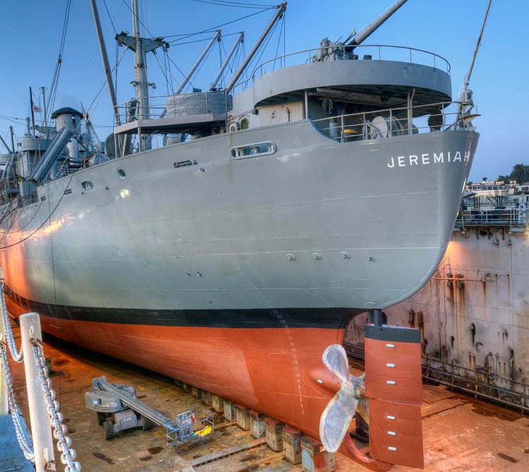
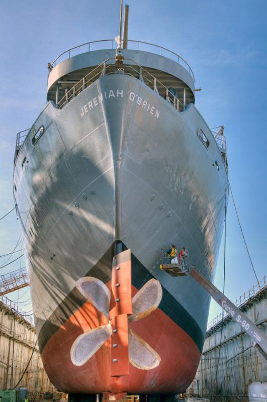
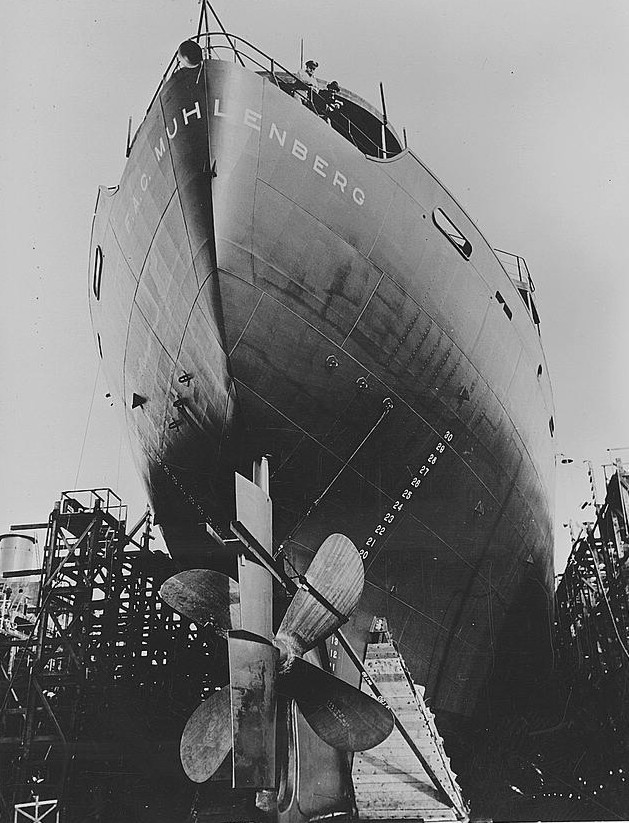
As to when this rudder design was adopted, this pix shows the Liberty F.A.C. Muhlenberg with a contravene rudder prior to her June 1942 launching which was just two months after the Hopkins' launching so I think it's probable the Hopkins had one too.
I always like to learn something new.
Tim
-
Thanks Roger! That is some great info.
Although I spent most of my working life at sea I've never seen anything like that rudder. I suspected that the liberty ships had to make do with relatively simple, and cheap propellers since the shops capable of making more complex ones would have been monopolized by the Navy. The Liberty props don't look all that advanced over what John Ericsson would have used.
Thanks again for an informative post
Tim
-
Bob, for small areas I use Elmers Carpenters Color Change Wood Filler. It dries quick and sands easier than Bondo. For larger areas, or where I need more than minimal thickness, or where adhesion to the wood is an issue (like on a thin or pointed areas) I'll use Bondo.
Tim
-
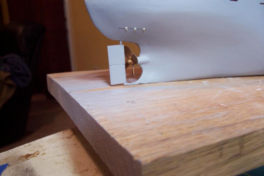
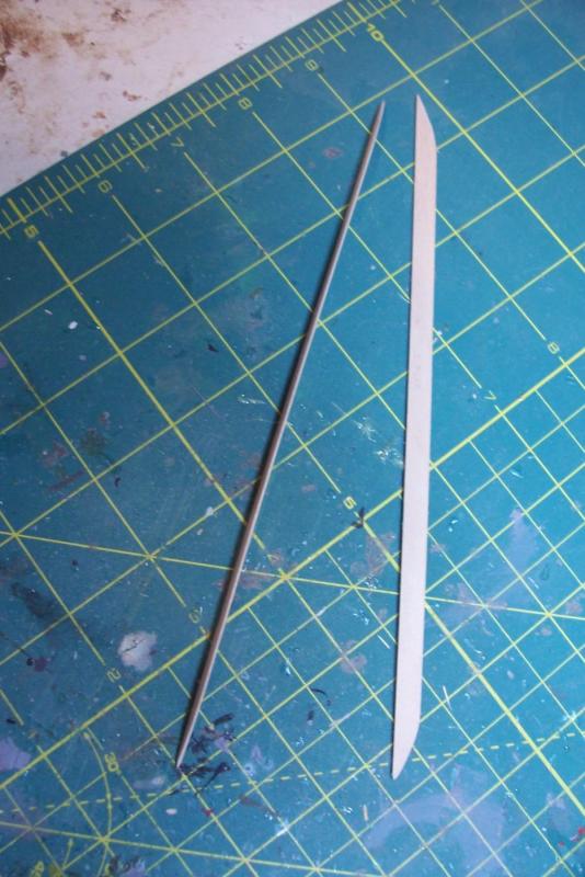
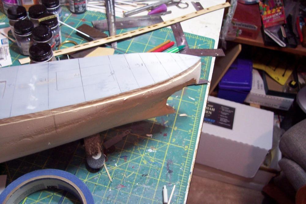
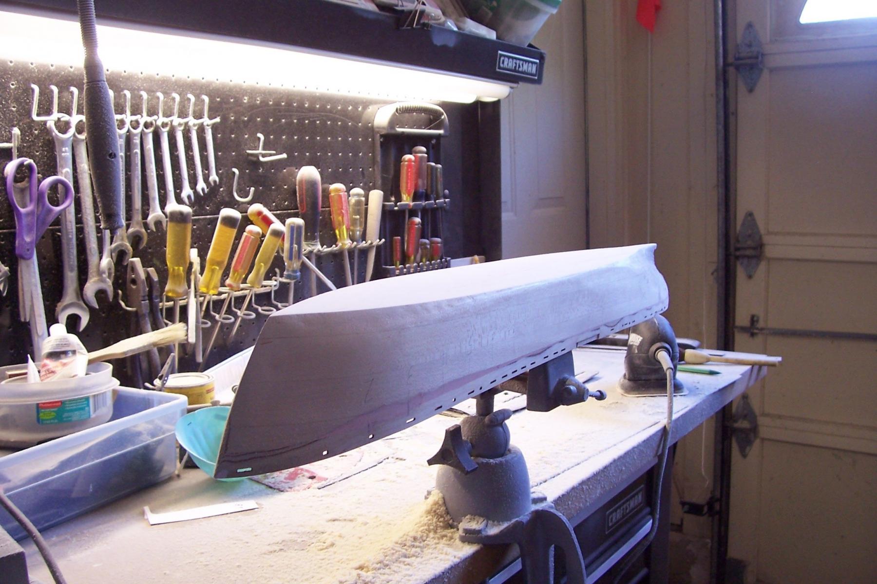
Running Gear
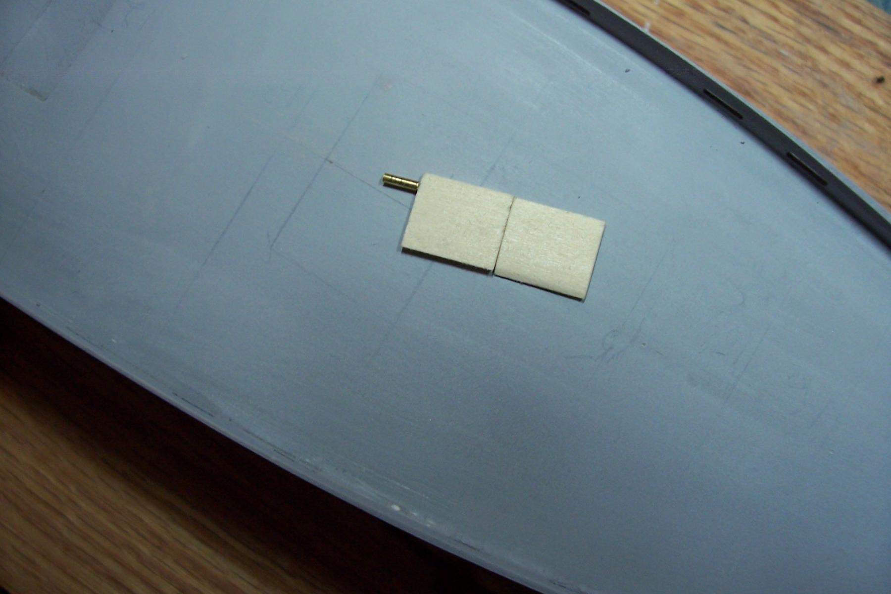
The Liberty Ships had a style of rudder that I have not seen before. It’s basically 2 airfoil shapes stacked on top of each other, the top one would give thrust to port and the bottom to starboard. The only reason for this that I can think of is that the relatively crude prop would have more side thrust than more complicated (and expensive) ones would so this was an attempt to reduce wear on the rudder bearings.
Here’s mine. For those who may build the kit I recommend using.20 wire drilled into the rudder , covered by 1/16 tubing above it. The 3/32 stock recommended in the kit is too big after the rudder has been shaped.

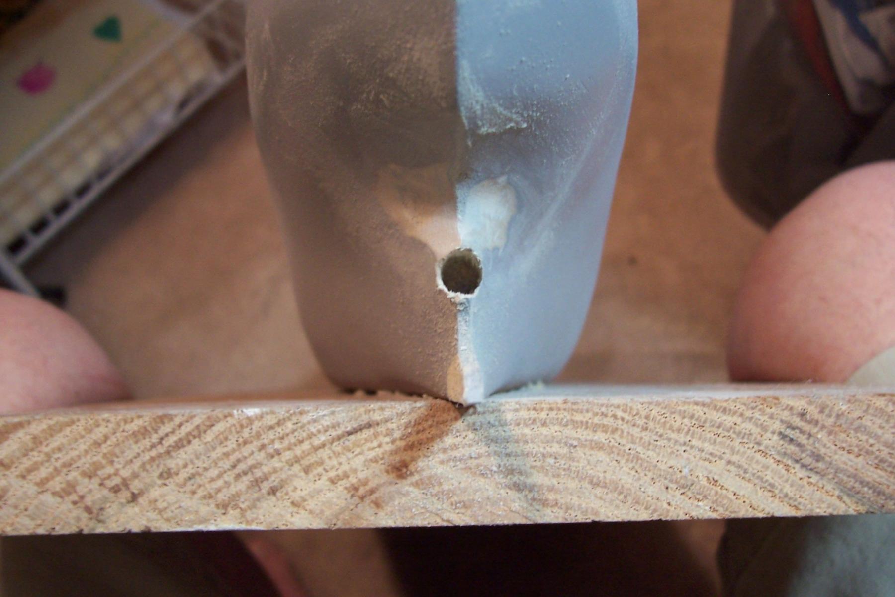
Drilling a 1/8 inch hole into the thin after section was a little intimidating, I started with a 1/16 bit and worked my way up.

After the shaft opening was drilled it was time to finish the final shaping of the hull in that area:

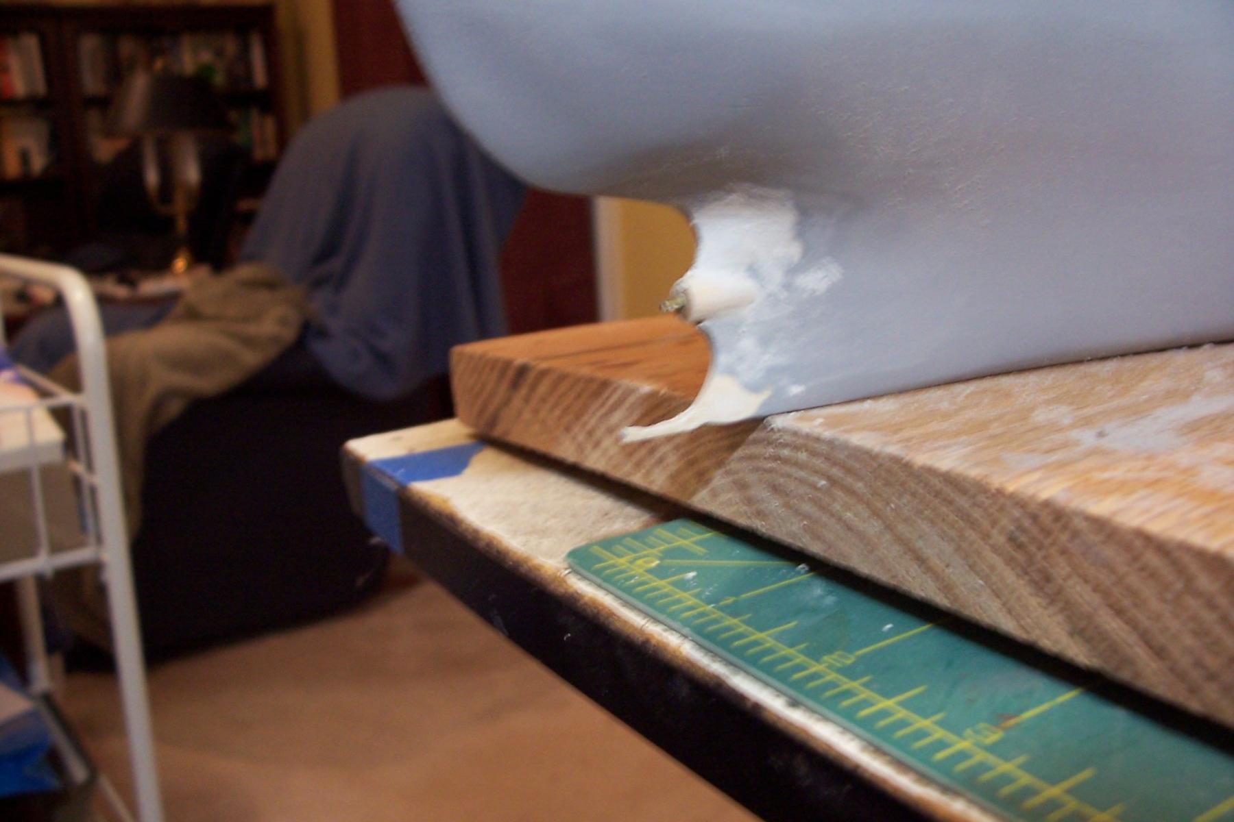
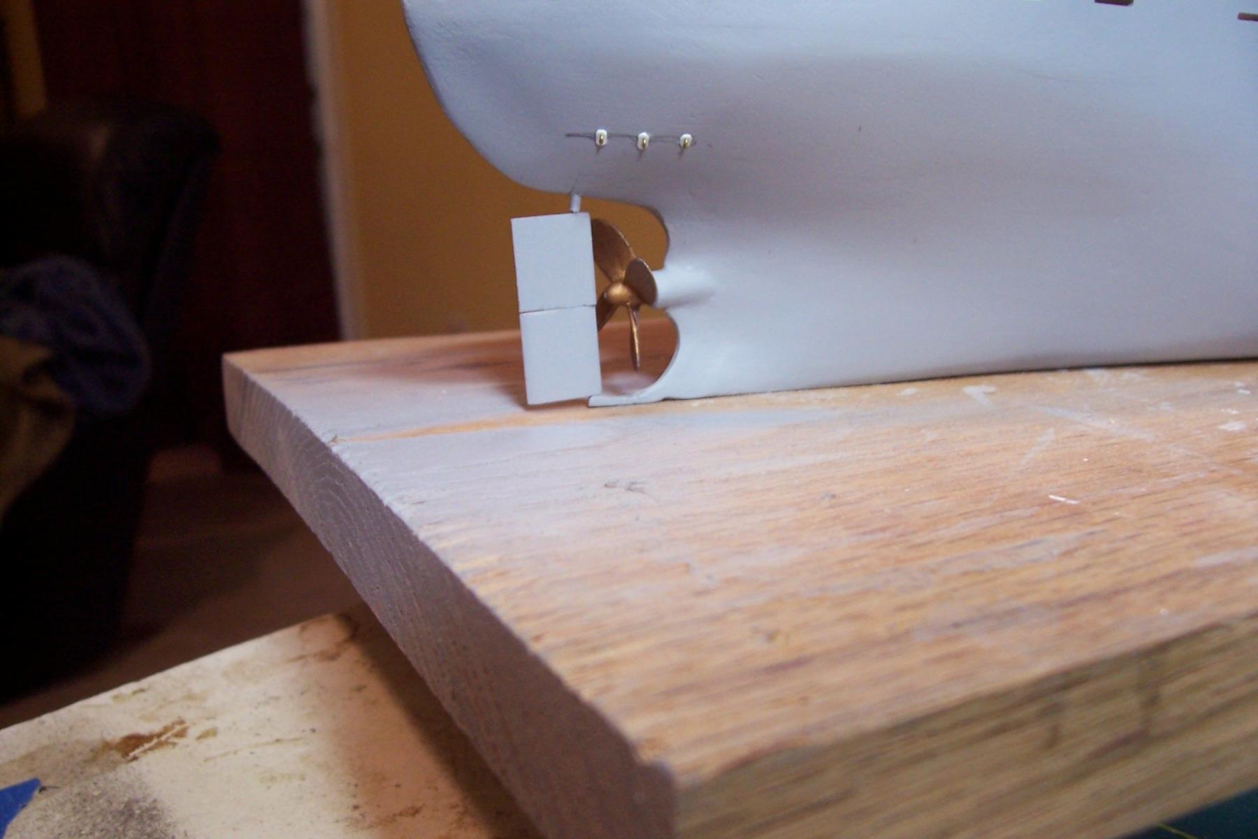
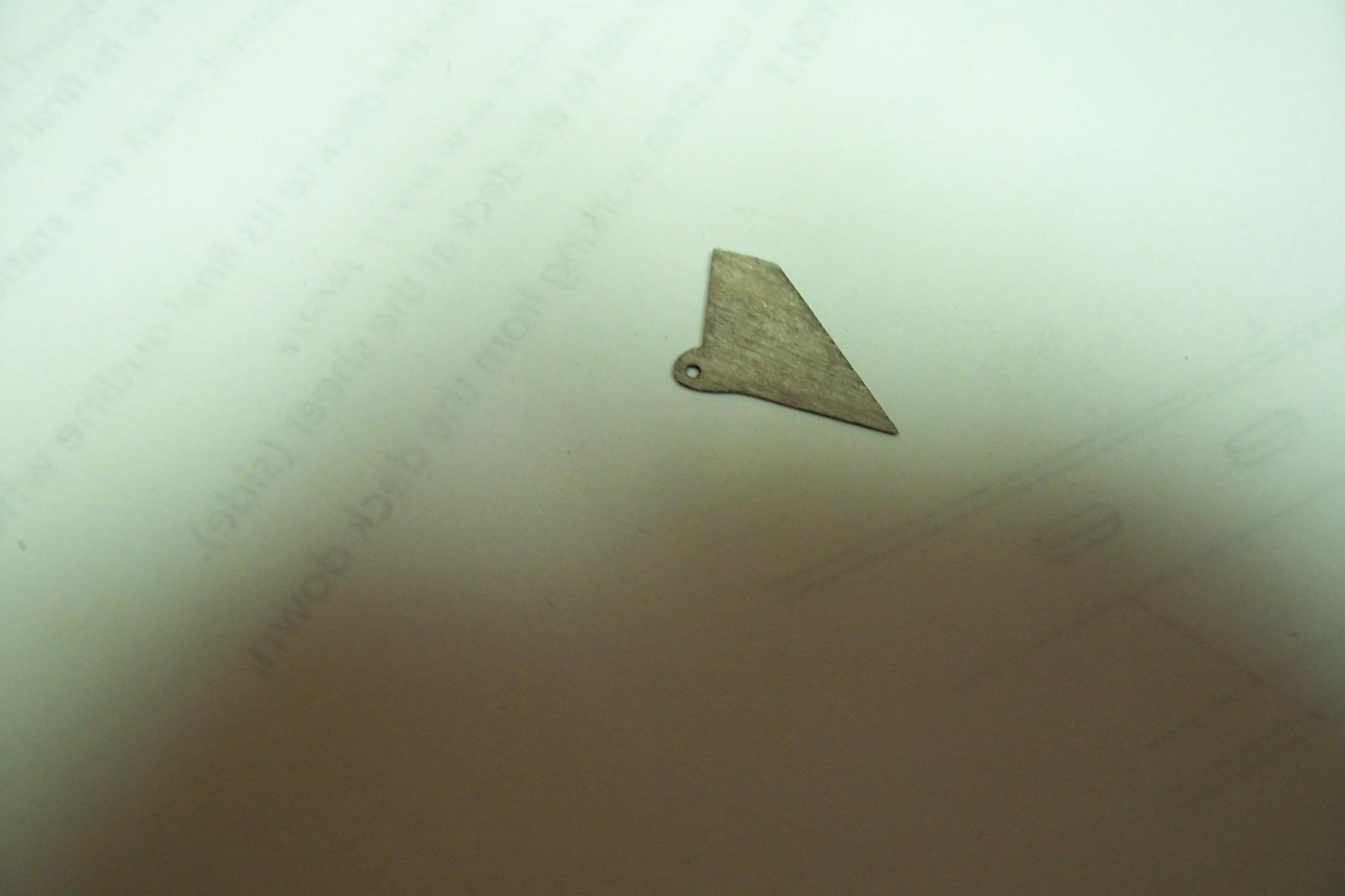
Here’s the final product ( the prop and rudder are off plumb because they are not glued in place, I’ll glue them near the end of the build to save them from getting wacked.) The eye pads above the prop are scratch, you can see the real things in the first 2 pix above.
The anchors were easy to add. At this point the hull “outside the lifelines” is done except for painting.
-
-
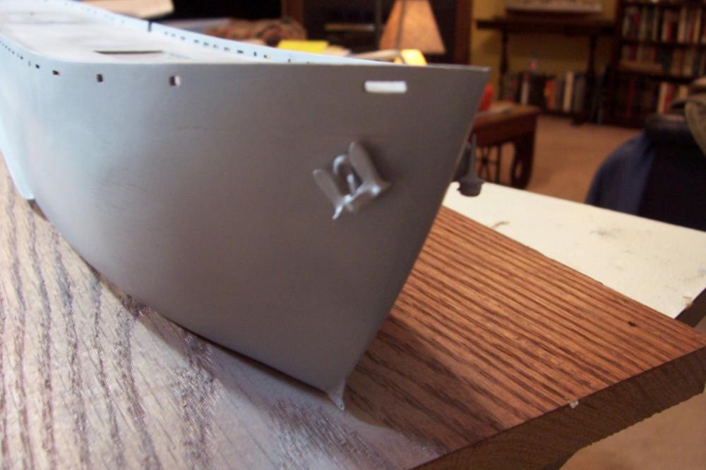
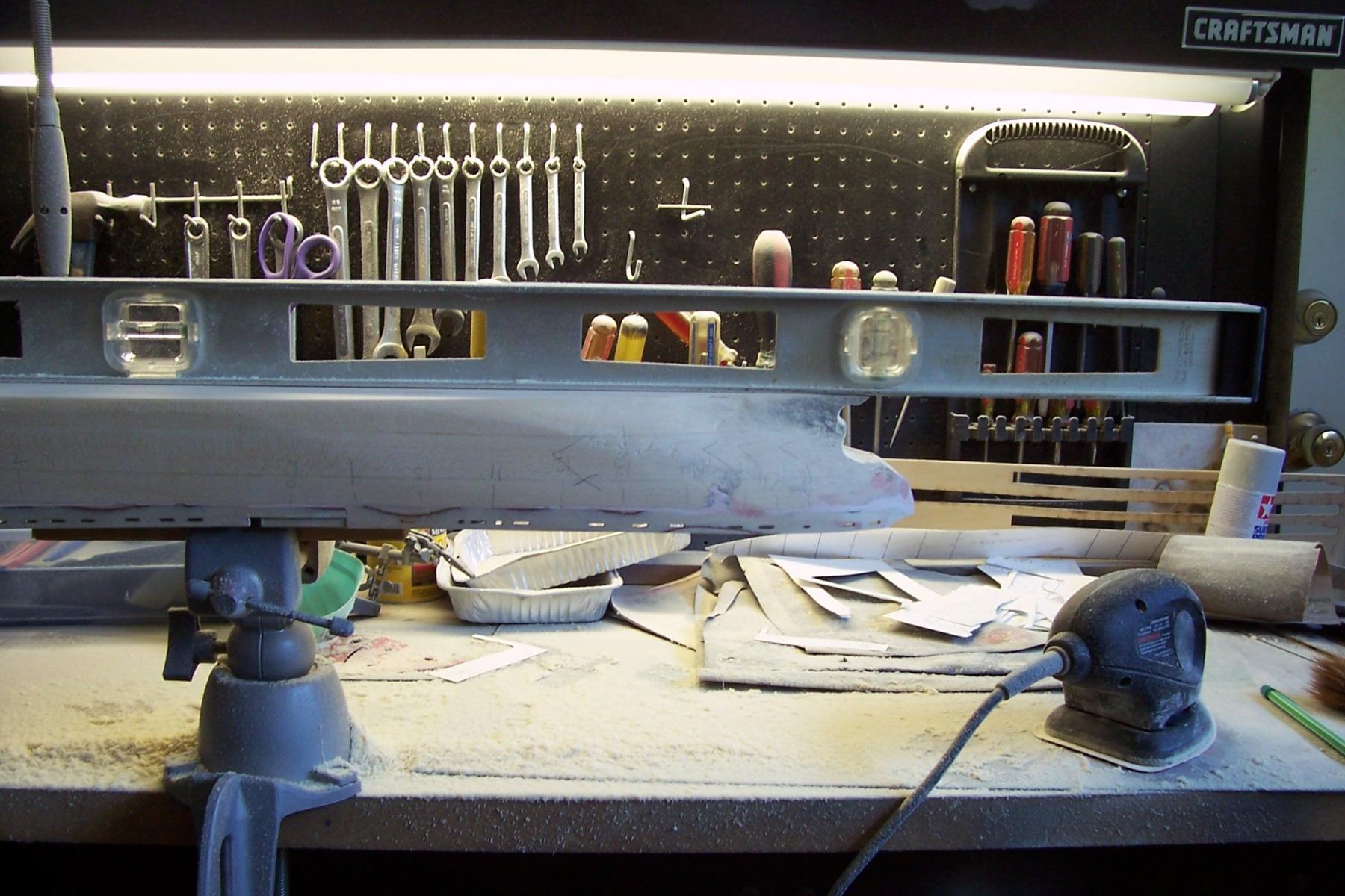
Underwater stuff
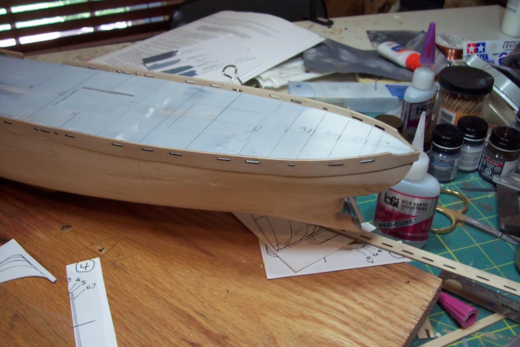
The first item to add is the Paravane Chain Bracket to foot of the stem. The kit provides a nice piece of laser cut ply for the bracket:

After cutting a thin slot in the stem with a razor saw it slides into place:
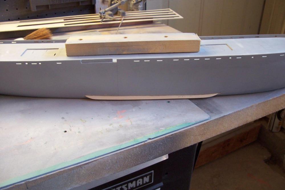
The bilge keels are next. They are first cut to length, then the ends are shaped and finally both sides are sanded to bring the outboard edge to a knife-edge:
The slots are marked on the hull using the drawings. These are fairly straight with almost no rise at the ends, probably because with this hull shape and an 11 knot top speed these ships did not throw much of a bow wave. The slots were cut with a hobby knife and deepened and widened with a narrow file:
The starboard bilge keel in place prior to touching up with filler and primer:
Next up will be fabricating the rudder and prop shaft.
-
Red- thanks for the kind words.
David B - I thought about adding plating with aluminum tape ( the thickness of sheet styrene would be over scale) but after playing with it on scrap wood I've decided not to. 90% of it looked OK but there were enough problems (wrinkles, uneven edges, etc) that I had no doubt I would have ended up stripping it all off. I've got a good, smooth finish on the hull and I'm just going to go with that.
-
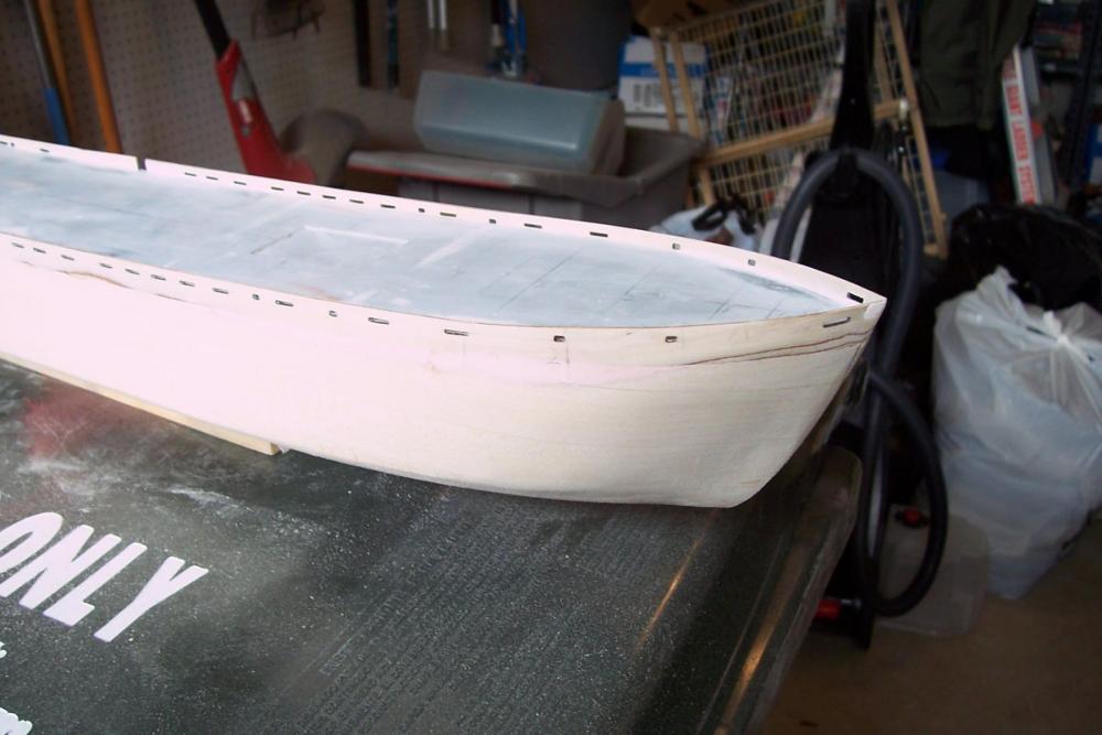
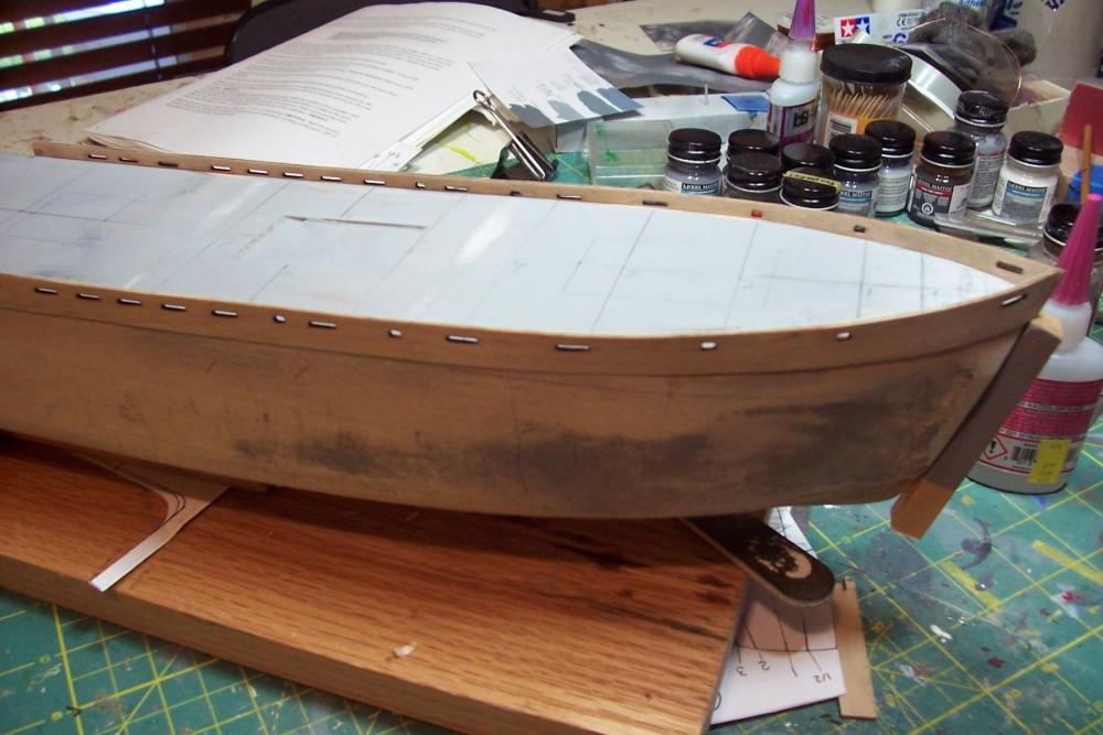
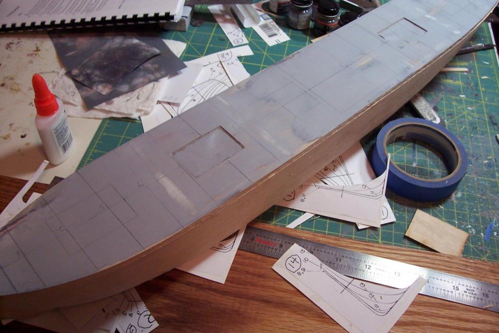
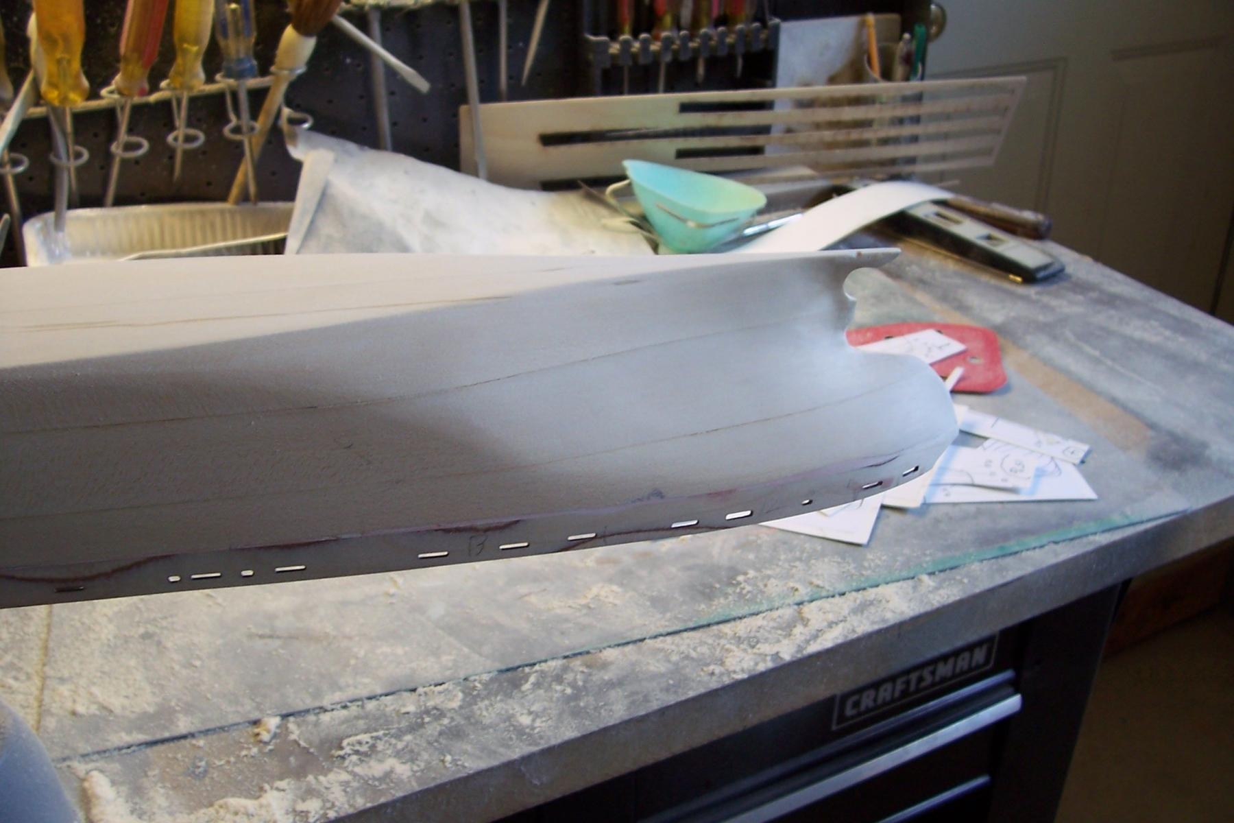
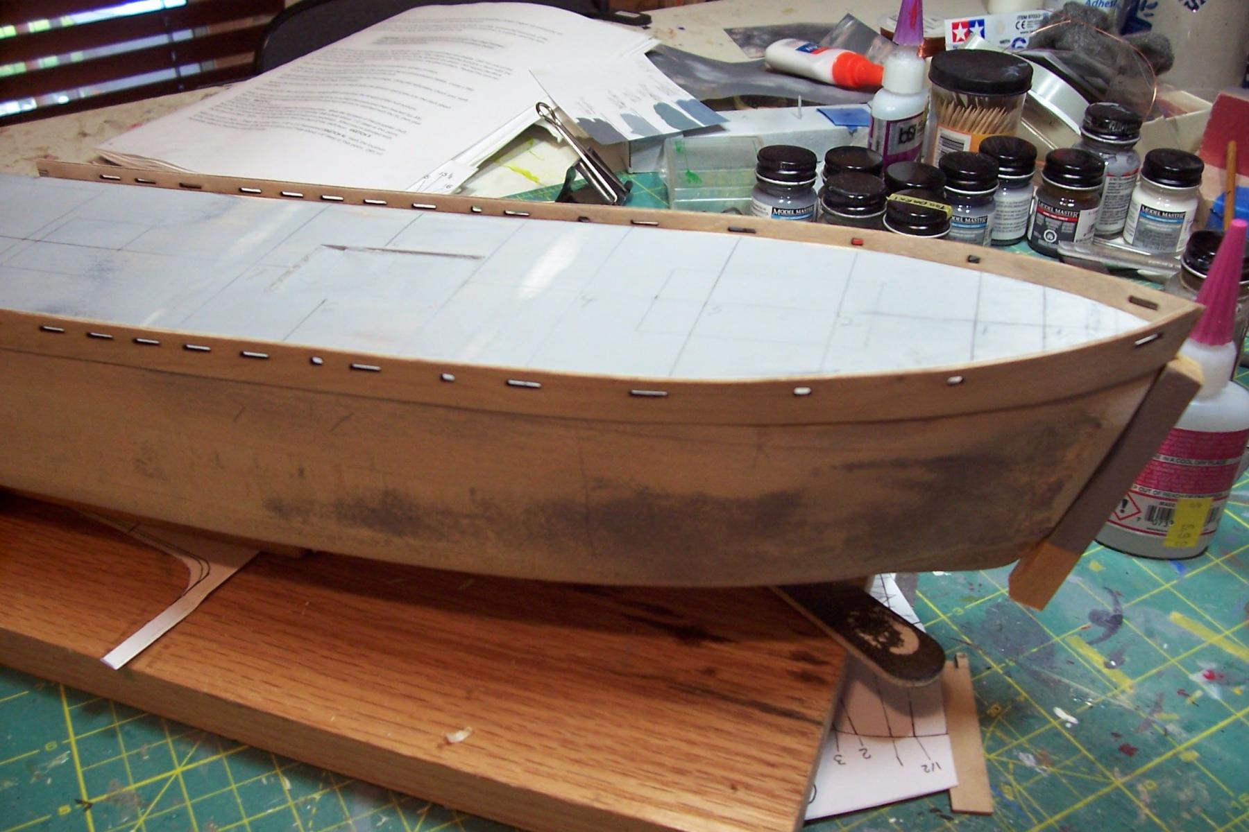
Hull shaping done
I’ve finished the initial shaping the hull using the templates (adjustments may be needed based on what the primer shows). Some minor file and hobby knife work remains to be done around the rudder post and shaft housing to make sure the prop and rudder fit OK.
The first smooth sanding is done, now it’s a matter of priming and resanding, repeated as needed to get a smooth “steel” finish.


- Ryland Craze, WackoWolf, Red and 11 others
-
14
-
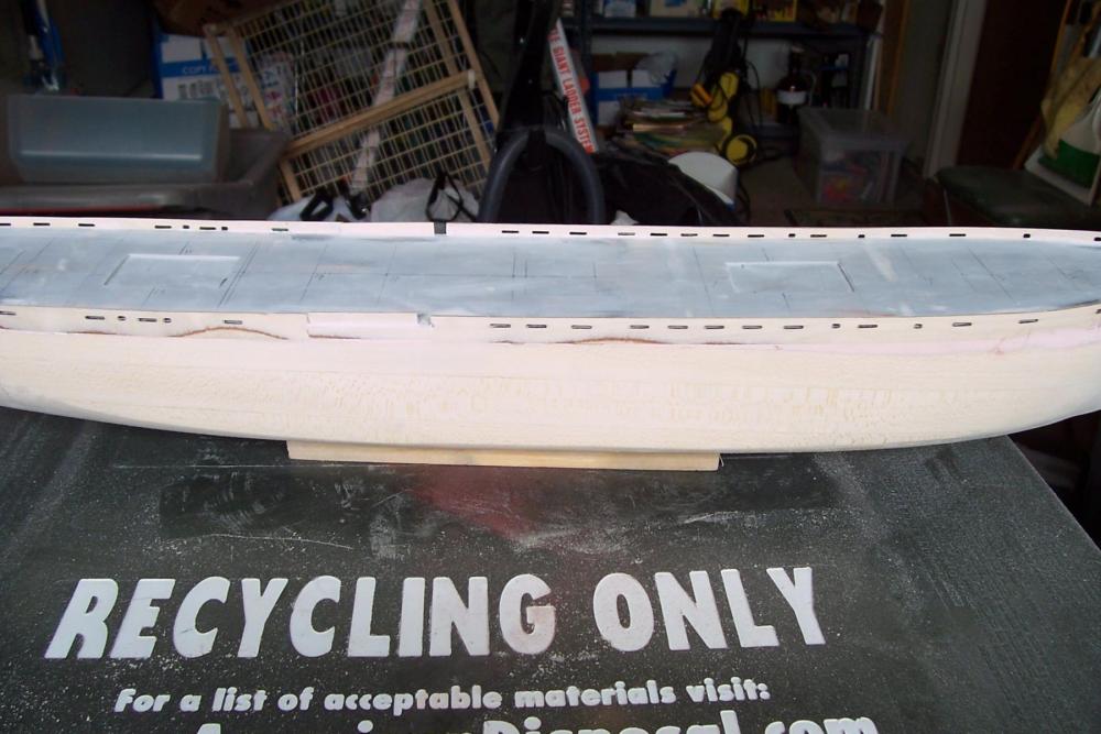
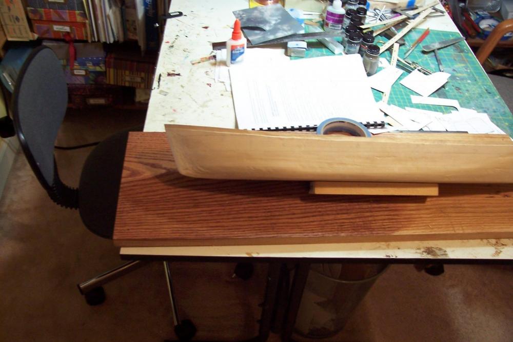
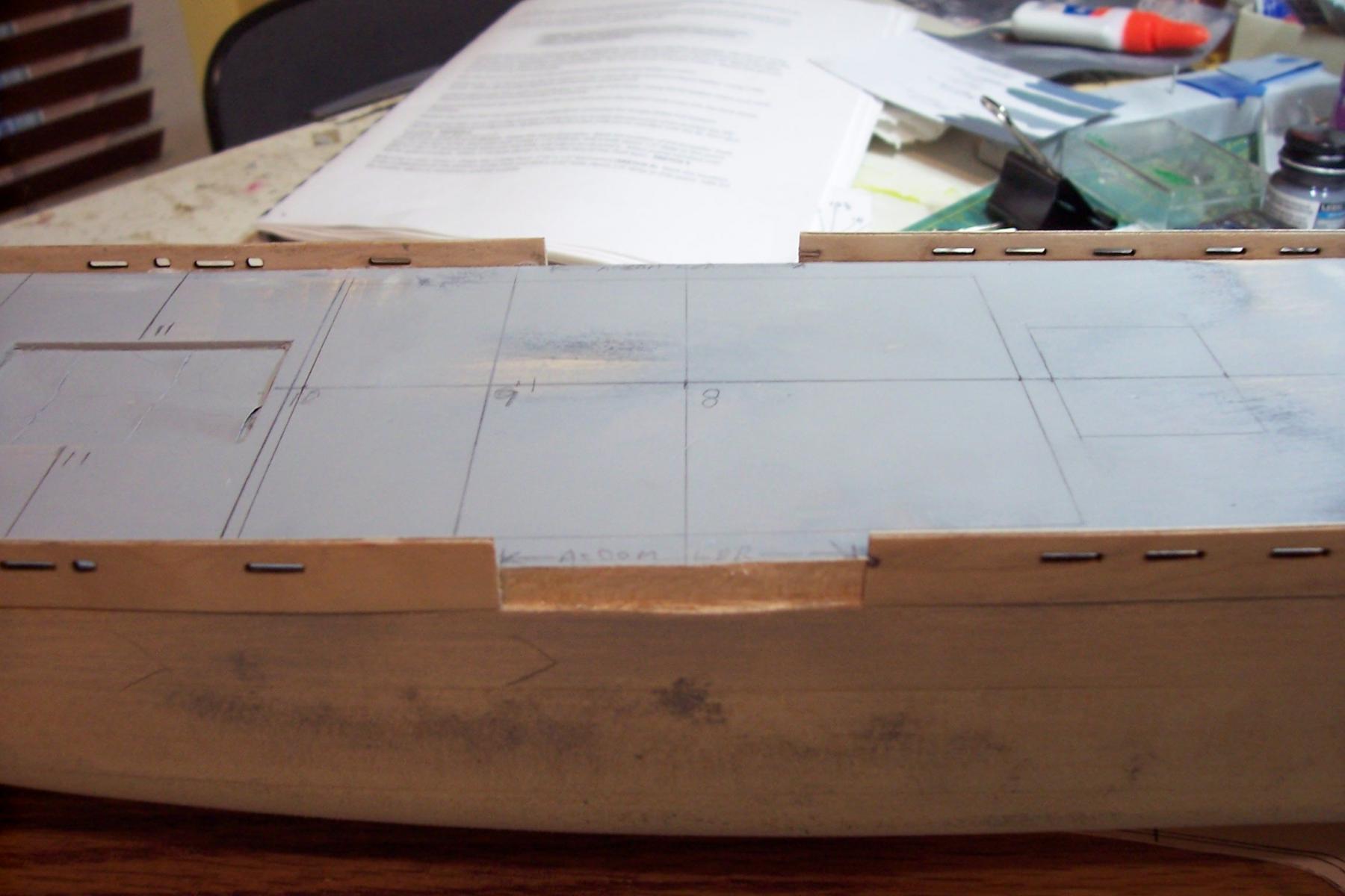
The hull bottom
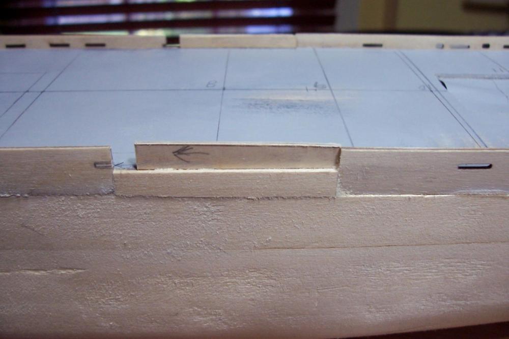
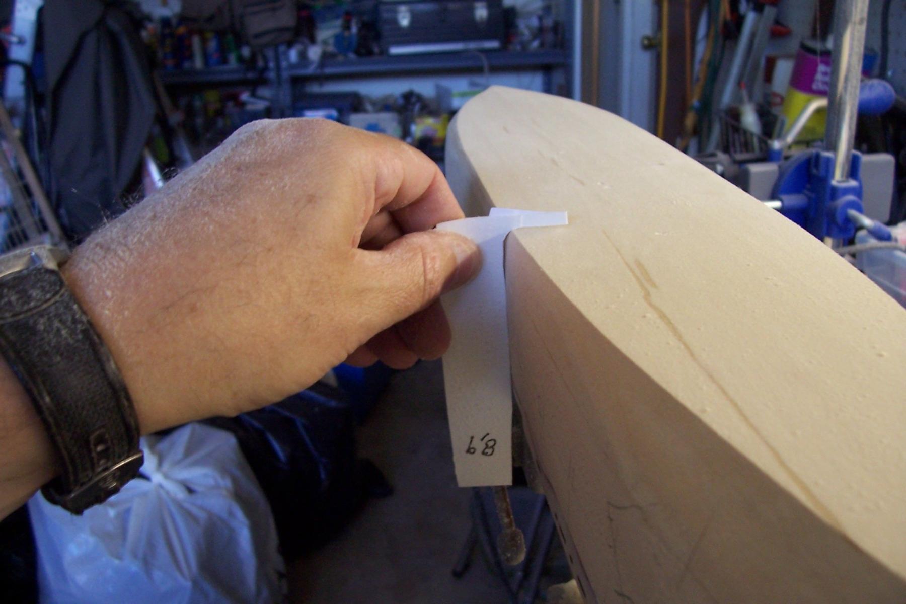
This is the 4th solid hull kit I’ve worked on and the first where I have had to give any thought to the bottom of the hull. With “traditional” hulls you shape the sides, which extend to the keel. Any discrepancies between the main deck to keel height on the plans and what comes out of the box is usually taken care of by taking some wood off the main deck (i.e. lowering it), although I have never had to do that.
In the hull design of the Liberty ships the bottom of the hull is really a separate, distinct area. For most of the length the hull is a box shape with vertical sides and a flat bottom. After shaping the sides I was not happy with the curve of the hull between the bottom and sides - it should be a very small radius curve, basically a 90-degree angle that is rounded. The rough hull in the kit has a much larger radius curve, leaving a gap at the corner of the templates.
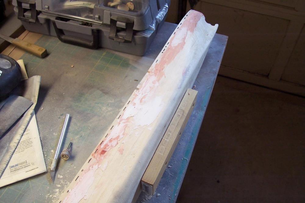
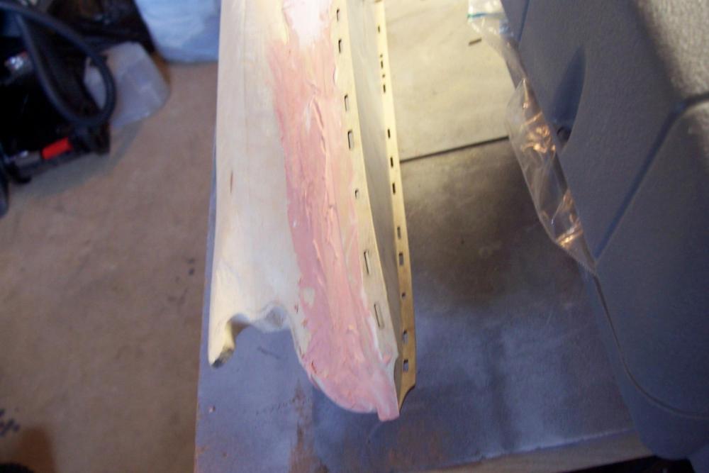
There are only 2 options to address that; take more off of the sides or off the bottom. The sides cannot be reduced anymore without affecting the dimensions of the main deck or inaccurately slanting the sides toward the keel - they would no longer be perpendicular. So the answer was to take wood off the bottom. To find out how much I had to play with I compared the keel to bulwark measurements with the plans (something I should have done earlier) and found that the my hull was 3/16 to 1/4 inch too tall. Obviously the hull was machined to allow for this - I just didn't think to check it. Taking off that amount of wood would solve 3 issues: it would reduce the radius of the turn of the bilge, it would make the hull match the plans and it would fix a problem with the bottom - it should be dead flat from the foot of the stem to the tip of the rudder rest but as you can see below mine had a rise towards the stern:
After several boring hours running a hand-held sander back and forth across the bottom everything fell into place. The curve at the turn of the bilge is good, the hull height matches the plans and the keel is flat.


Next will be shaping the stern area, priming the hull and then resanding to remove rough spots and low areas (like the ones you can see in the photo above).
-
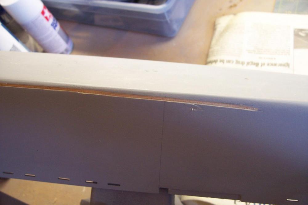
David,
It's neither. The bulwarks fit tight, inboard and outboard and are flush to the hull. I think what you are referring to is that the bulwarks are made out of 5-layer (very thin layer) plywood and as I sanded the outboard sides some areas had to give up more wood than others so what you see is the 2nd, and in some areas, the 3rd layer (they alternate between light and dark wood for some reason.) When I prime them the bulwarks will appear as part of the hull without seams. Any variations in the bulwark thickness will be hidden by cap rails which i intend to install, both for accuracy and to provide more drilling/glueing surface for the 100+ pad eyes and eyes that will sit on them along most of its length.
-
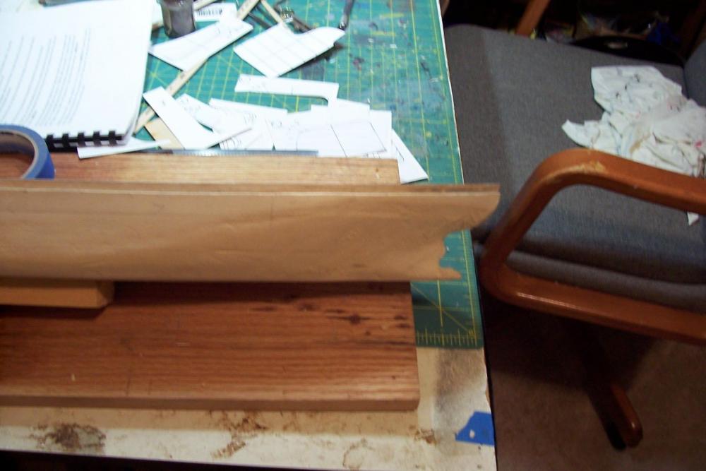
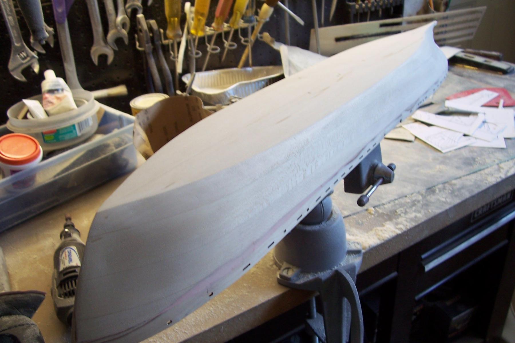
Hull shaping
When I first read through the directions I was surprised to see that the bulwarks were attached before the hull was sanded - I thought they would be fragile and would complicate the hull shaping but I pressed the “believe” button and went with the kit’s building sequence - I’m glad I did. Trying to add them after shaping the hull would have led to inevitable “knuckles” at the joint, requiring even more sanding and they probably would still have not looked right. By adding them first they are treated as an integral part of the hull and after sanding they are fair with the hull. The design and depth of the rabbet also makes for a very secure joint so I have no more worries about them.
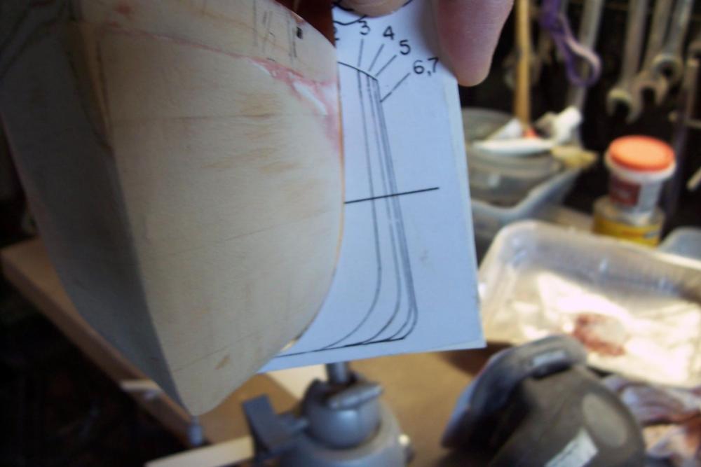
The sanding to shape of the hull is going relatively quick and easily, mainly because of the simple shape of the hull (bluff bows with no flair, slab sides amidships). Here's an example of how the templates are used to check the shape of the hull:
At this point the forward 75% of the hull has been shaped and rough sanded, the stern area is next and will probably take as much time as the rest of the hull combined because of its shape and the need to thin it.
This basswood sands very easily yet keeps an edge, nice stuff to work with.
-
-
Bulwarks installed
The fore and aft bulwarks have been glued in place and a piece of square stock added to the stem to ensure there is enough wood there when the hull gets shaped. I probably will end up sanding all of it off but it is easier to attach now then when the stem gets narrow so better safe than sorry:

The midships gap (indent) is where the accom ladder will go. Scrap wood was used to fill the unused section of the rabbet:

Wood filler has been added to the seams and everything is ready for the hull shaping:
- Captain Slog, John Allen, cog and 10 others
-
13
-
Rabbet finished
Cutting in the bulwark rabbet along the deck edge with a hobby knife went OK.
The bow and stern profiles have been shaped using templates (the shaping of the hull itself has not started yet.
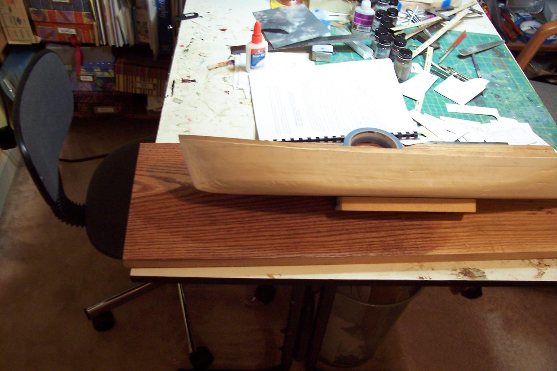
This is a good place to break while I head out of town for a week and a half.
When I get back it will be time to add the bulwarks and then shape the hull.
-
Welcome aboard Carl!
As you follow along please bear in mind that this is the updated version of the kit (which happened in 2009 I think) if you got yours before 2009 your kit may not have as much laser cut wood as you will see here. If that's the case you could always order those parts you want from BJ when you are ready.
-
Cargo Hatches finished and rabbet started
After sanding and priming the deck fill sheets blend in nicely:

Progress will be slow for a bit while I cut the rabbet for the bulwarks around the circumference of the main deck (given the size of the hull it works out over 4 linear feet). I was going to try using the Dremel tool but after practicing on scrap wood I discovered that while it can deliver accurate and consistent wood removal in one dimension, the second dimension is not as good so I’m going to go with the kit directions and take it slow with a hobby knife. Another reason for using the knife is that I want to angle the rabbet around the bow and stern so that the bulwarks will "tilt" out slightly and so be fair with the angle of the sides of the hull in those areas. The rabbet is 1/4” high and will be 1/16” deep.
-
Cargo Hatches (cont)
Fake bulkheads with stiffeners were added to the fore and aft bulkheads since they can be glimpsed thru the main deck hatches. I decided to just order a couple of extra hatch covers from BlueJacket for the Tween Decks rather than make my own so they would be consistent with the main deck ones:

The main deck fill pieces were easy to fabricate and fit snug enough that they do not move around.

Next steps will be to glue the fill pieces in place, fill the gaps with Bondo, sand and prime.
- Captain Slog, Elijah, cog and 11 others
-
14
-
Welcome aboard John, good luck on the Portland, I've always thought she works up to a great looking model. Understand how time gets away from you on a build but 2 years isn't really all that long for a ship like the Portland, plus the fun is in the work not the finish.
-
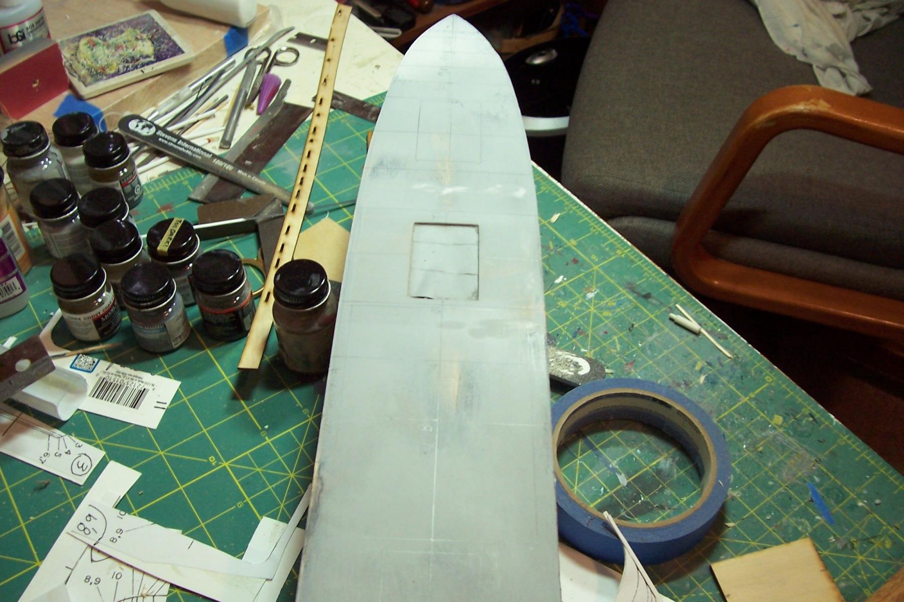
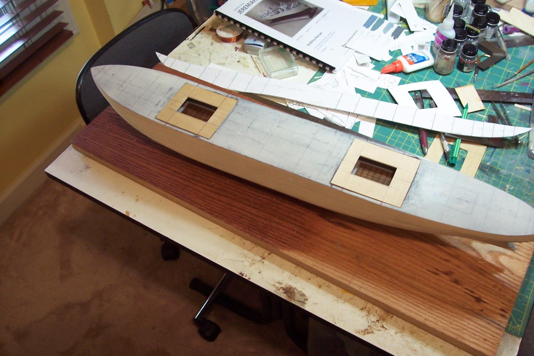
Cargo Hatches at final depth
The # 2 and # 4 cargo hatches are now at their final scale 10ft depth and a 1/16” deep rabbet has been added around the edges for the ply deck replacements to sit in.
The paper mockup resting on the deck gives some idea of how much of the interior will be visible. Since a little of the fore and aft bulkheads can be seen I will detail those with stiffeners, the sides on the hull are not visible so I won’t have to do anything there. The wood square on the deck is a placeholder for the Tween Deck hatch that I will make to match the main deck hatches.
- cog, Piet, Captain Slog and 7 others
-
10
-
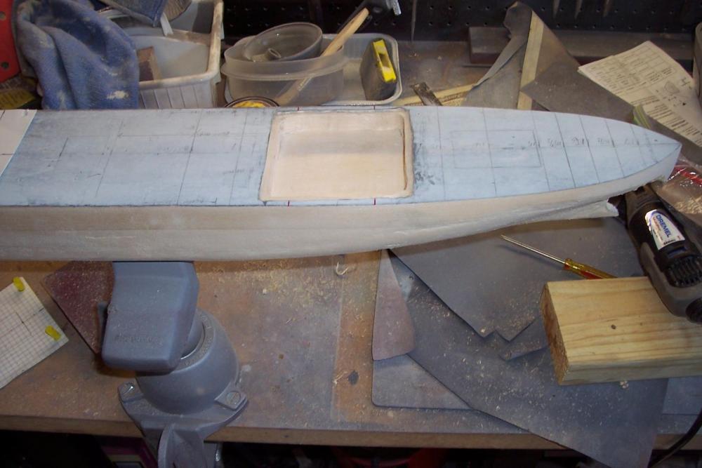
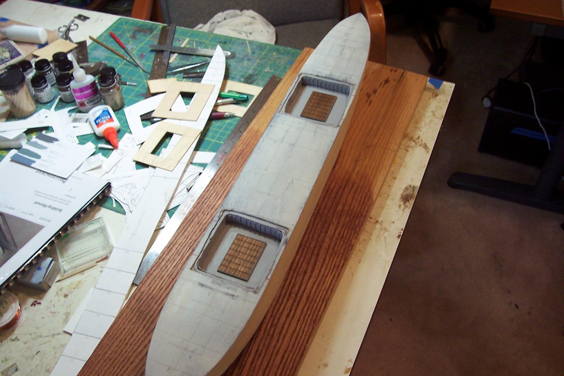
Opening up some cargo hatches
In thinking about how I want the finished model to look I decided that rather than have each of the 5 cargo hatches and their associated booms looking basically the same I will try to rig each one with a different style of rig and also show at least one hatch with the hatch covers removed. I decided to open up the #2 and #4 hatches.
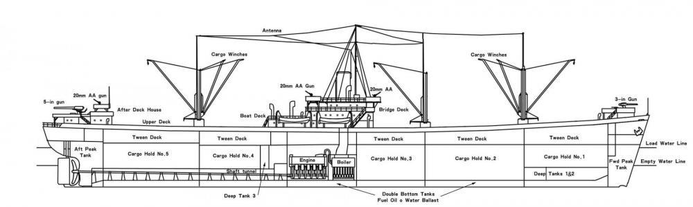
Each cargo hold consisted of an upper and lower hold, divided by the Tween deck. I will only go down as far as the tween deck since anything below the tween deck hatch would definitely be too dark to see. As you can see in this drawing the upper holds were only about 1/3 the size of the lower holds:
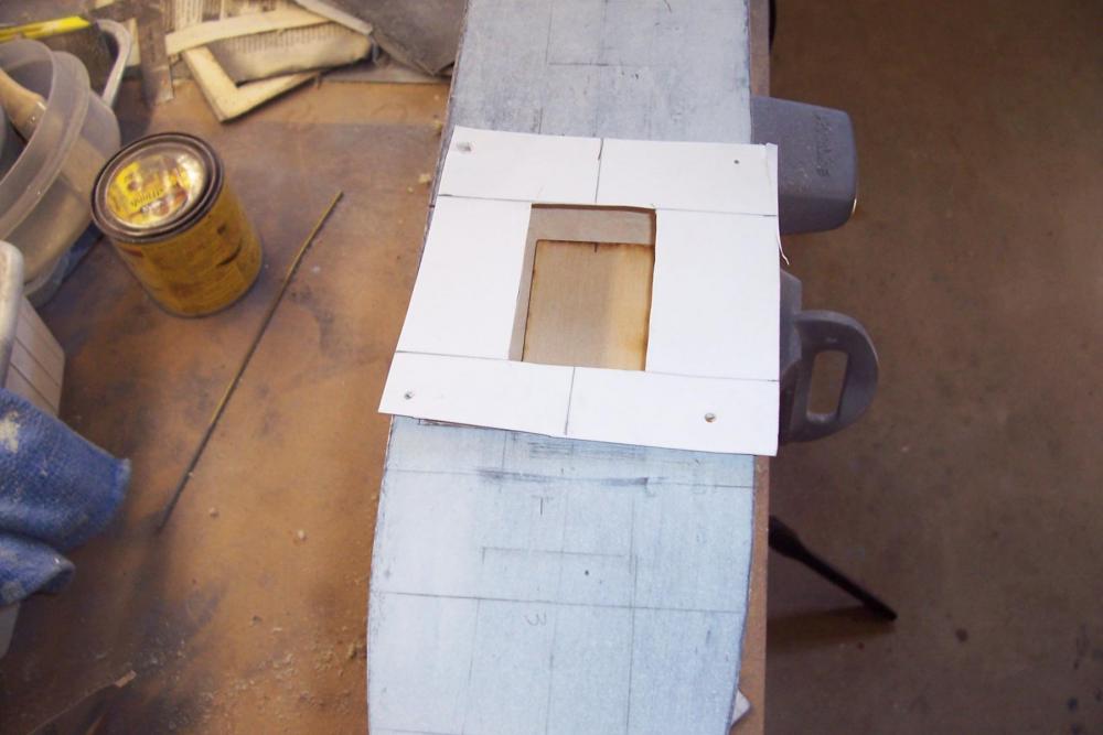
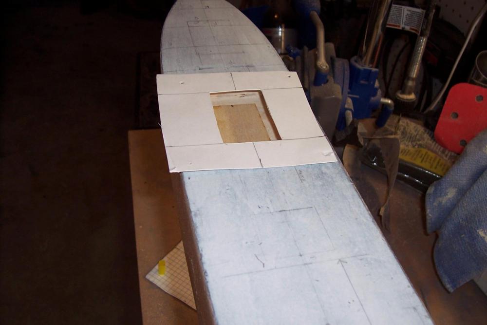
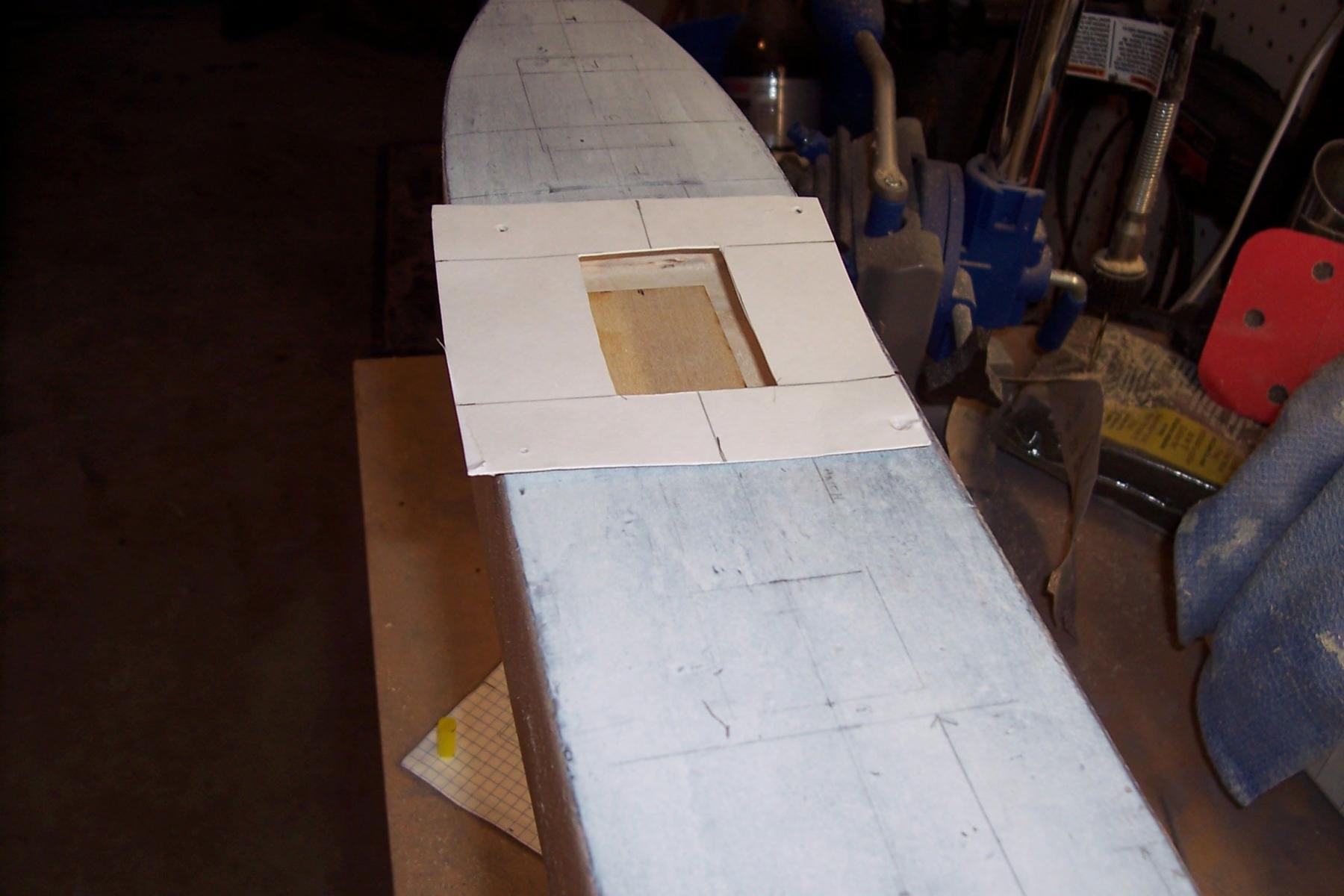
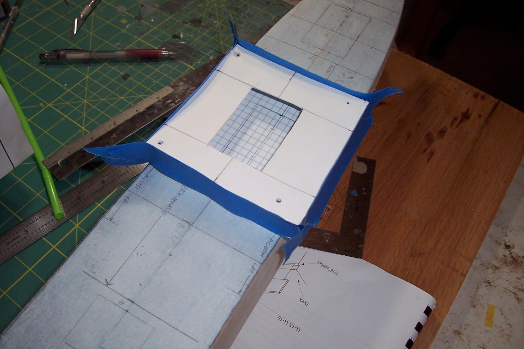
The hatches were relatively small in comparison to the size of the holds so in order to give them some depth I wanted to remove as much wood as needed horizontally so that the holds are visible when looking down through the hatch at various angles (this is assuming there is enough light to see in there, if not then no harm done - at least as much as can be seen will be somewhat realistic). In order to figure out how far back from the hatch combings I would have to “excavate” I made a simple mockup from cardboard with the upper hatch cut out and 4 straws cut to the scale 10ft length to separate the decks. The graph paper on the lower piece allowed me to figure out how much of the Tween Deck could be seen.

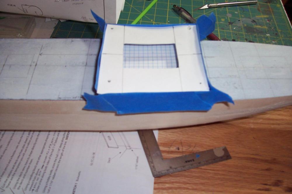
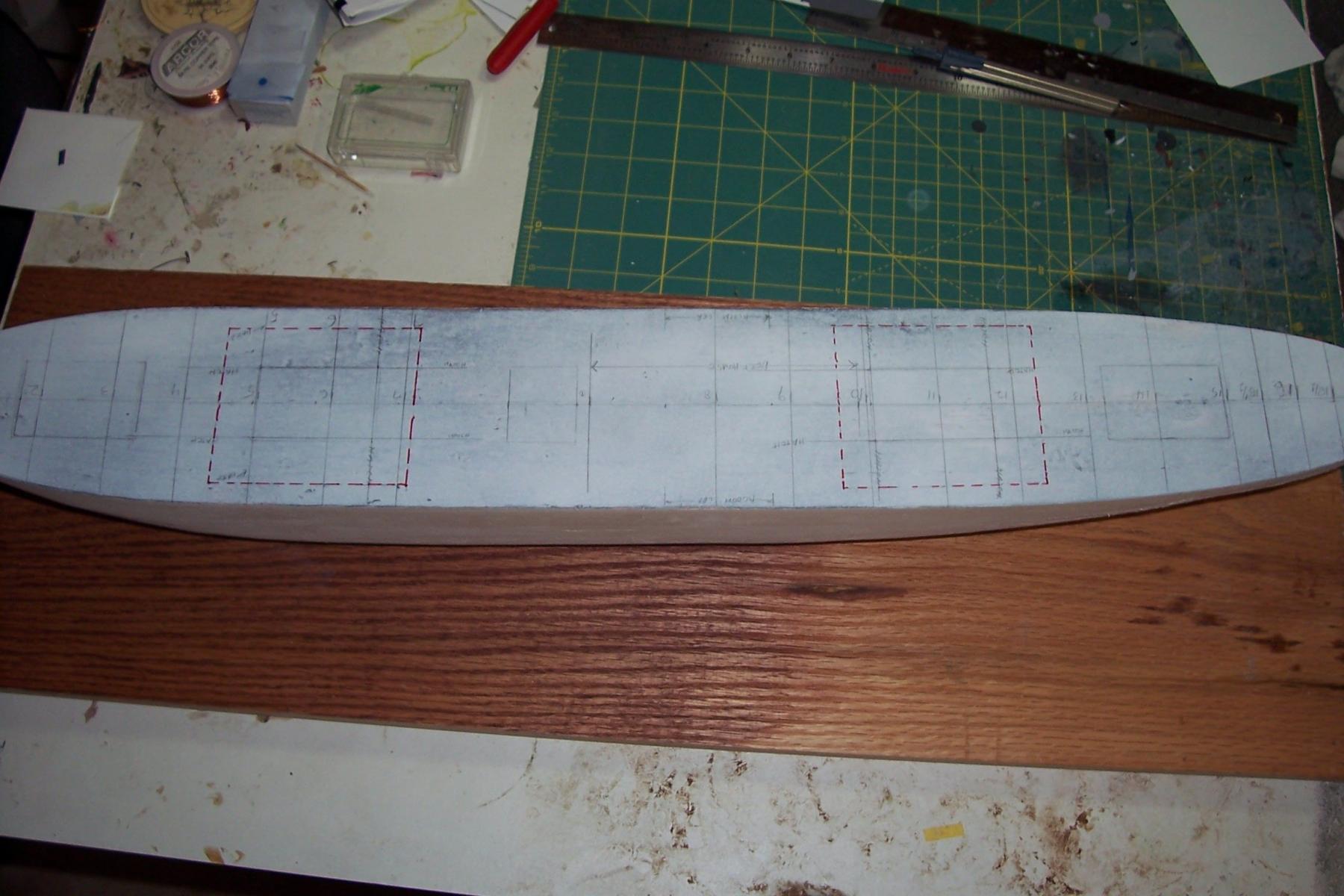
After getting my estimates and adding a little fudge factor I marked the deck in red with the areas to be excavated:

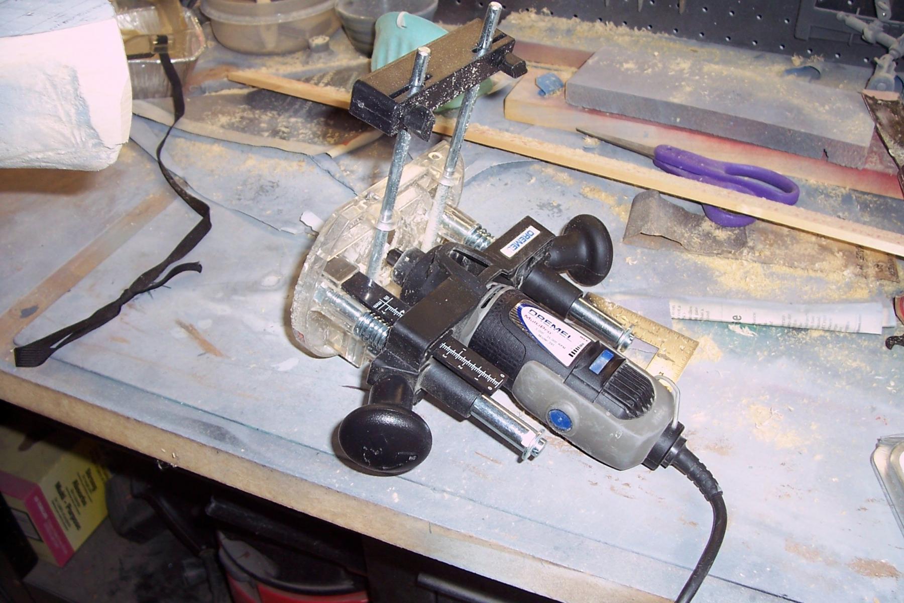
Fortunately I already had a router attachment for a Dremel tool so it was much easier than chiseling, although it will take multiple passes since it can’t handle taking off much more than 1/8” of wood at a time (the final depth will be 5/8"):

Here’s the progress so far, both holds are at about 1/3 of their final depth:
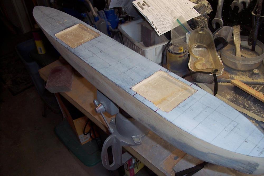
I’ll hopefully be taking off a few days for a fishing trip. When I return I’ll bring the holds to their final depth, add the tween decks and lower hatches, add the fore and aft bulkheads (if they can be seen) and then start fitting 1/16” ply to cover the openings, cut-out the upper hatches and then move on to other things.
- Elijah, Captain Slog, BETAQDAVE and 10 others
-
13


SS Stephen Hopkins by schooner - FINISHED - BlueJacket Shipcrafters - Liberty Ship
in - Kit build logs for subjects built from 1901 - Present Day
Posted
Welcome aboard daddy rabbit, your Scharnhorst looks to be a great build although seeing that PE bender brought back some disturbing memories from my last build (it was an Orange Hobby kit - a ton of unbelievably small and complicated PE)
Bob, thanks for the compliment. I tried textured spray paint that has worked well for me before but it just didn't work this time and since I've no shortage of sawdust with this build I thought I'd give it a try.