

schooner
-
Posts
640 -
Joined
-
Last visited
Content Type
Profiles
Forums
Gallery
Events
Posts posted by schooner
-
-
Lower Masts - some re-do and then done
After looking at the mast bands from my last post I realized something was wrong - I’ve never seen so many bands and of different sizes on any other build log. After looking at the AOTS ESSEX I figured out that I misunderstood what the plans were showing me; what I thought were larger mast bands were actually “wooldings” which are wraps of tarred line that bind things like the cheeks and fish to the masts so I took all the bands off and started over.
Here the front “fish” have been added to the fore and main masts (the fish protect the sails from abrading on the mast bands). One detail that I found on the AOTS book was the battens around the tops of the masts where the shrouds will rest. My guess is that they served to keep the shrouds far enough off the mast that air could circulate behind the shrouds and prevent wood rot from setting in. I have by no means checked every contemporary build log here on MSW but the only one I did find that included the mast battens was the one for the prototype build of Vanguard’s HMS SPHINX.
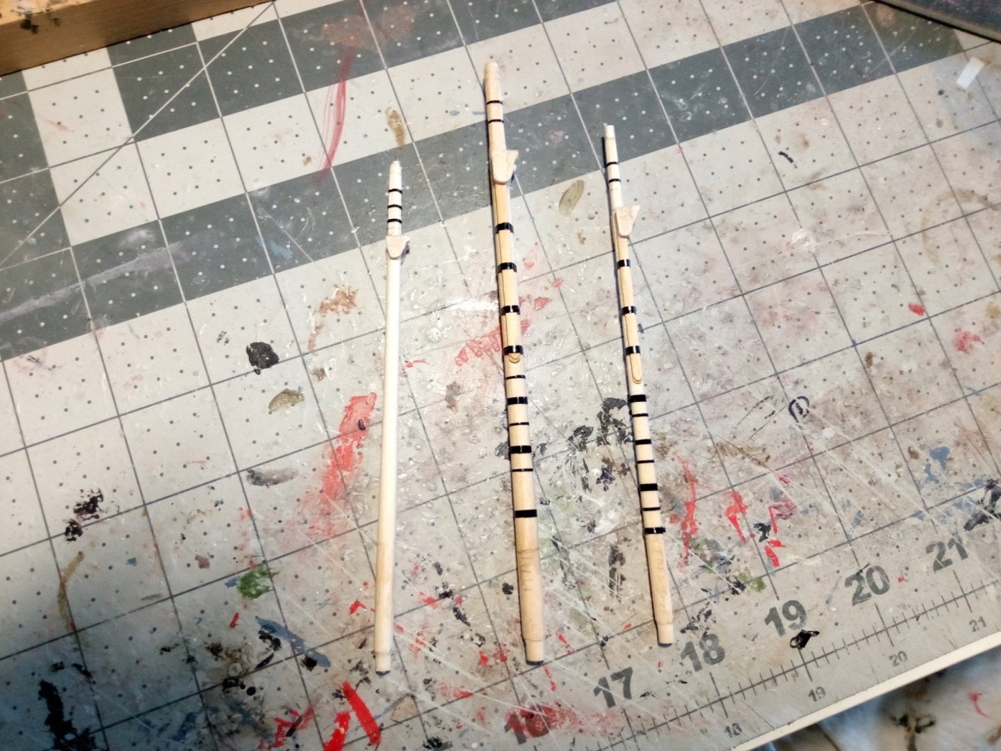
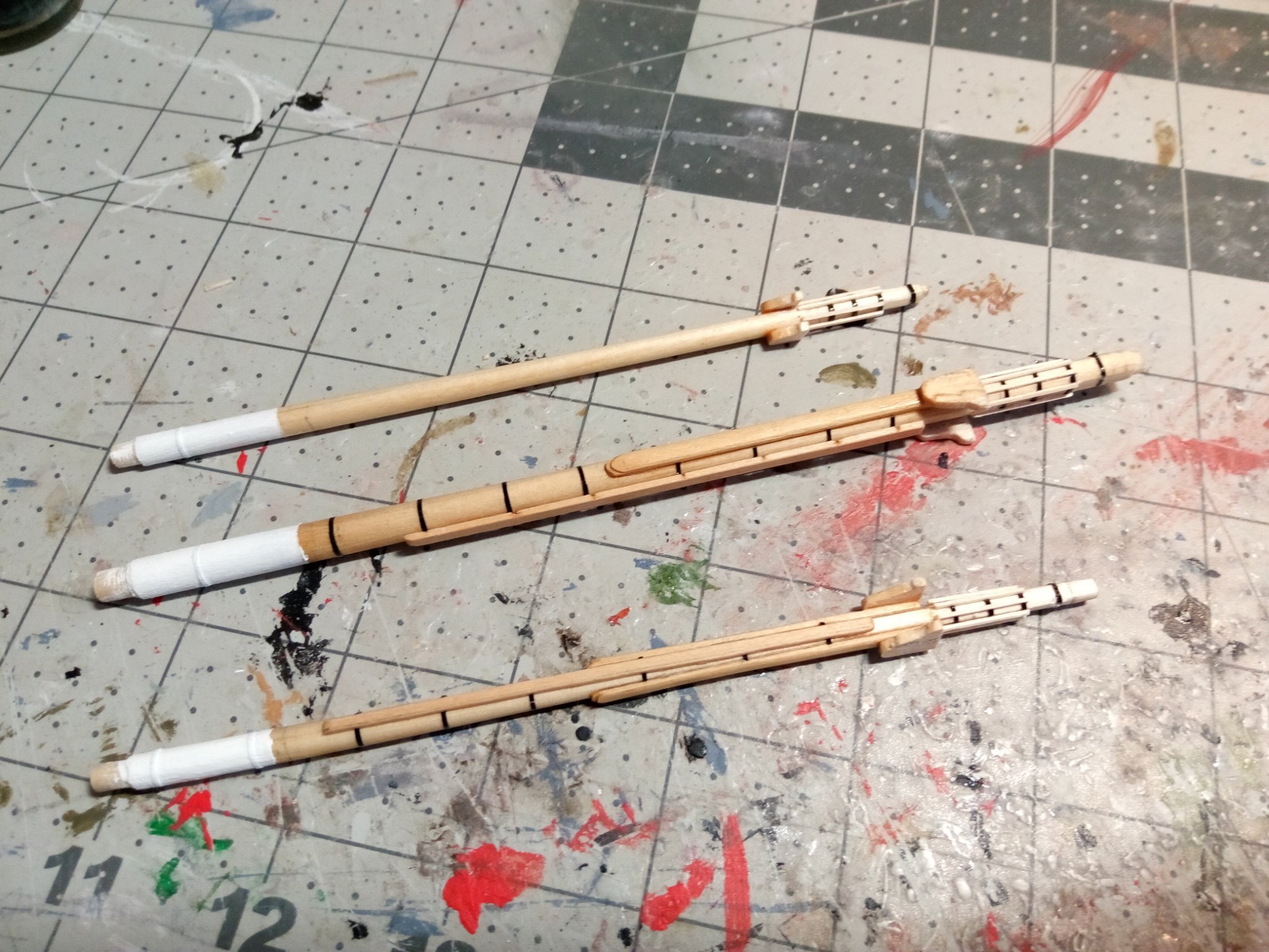
The last step was to spray everything with Testors Dullcoat to cover up the sheen of the pinstripe tape.Here’s the finished masts with the wooldings and addition of chocks on the main and fore masts for the stays and some cleats:
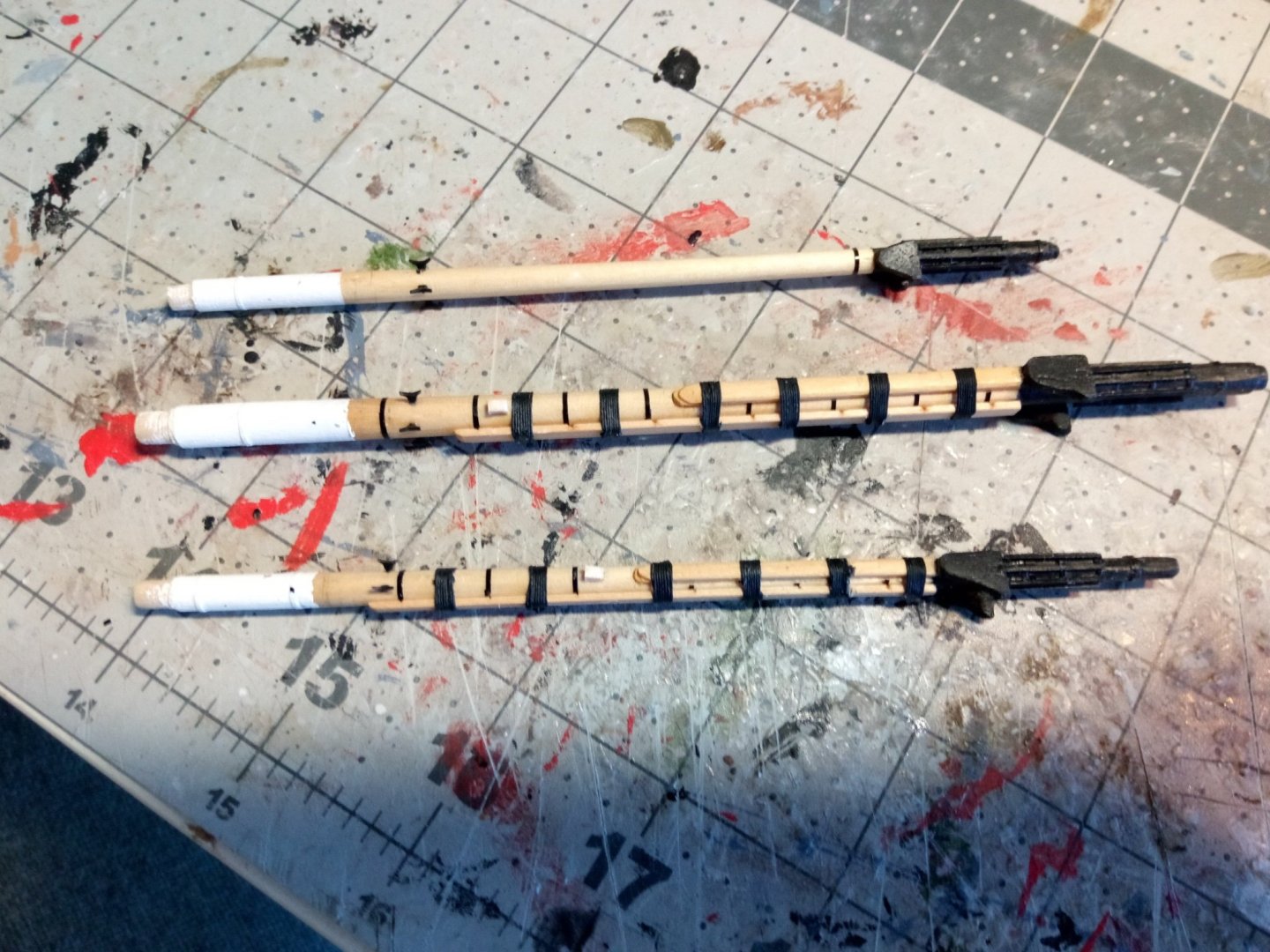
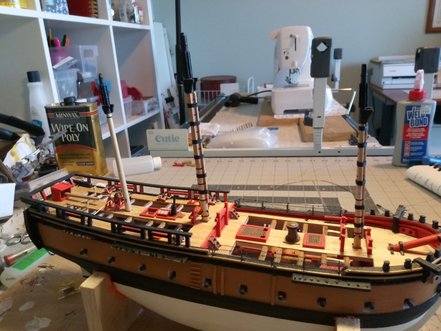
Next up will be the mast tops.
-
Lower Masts (cont)
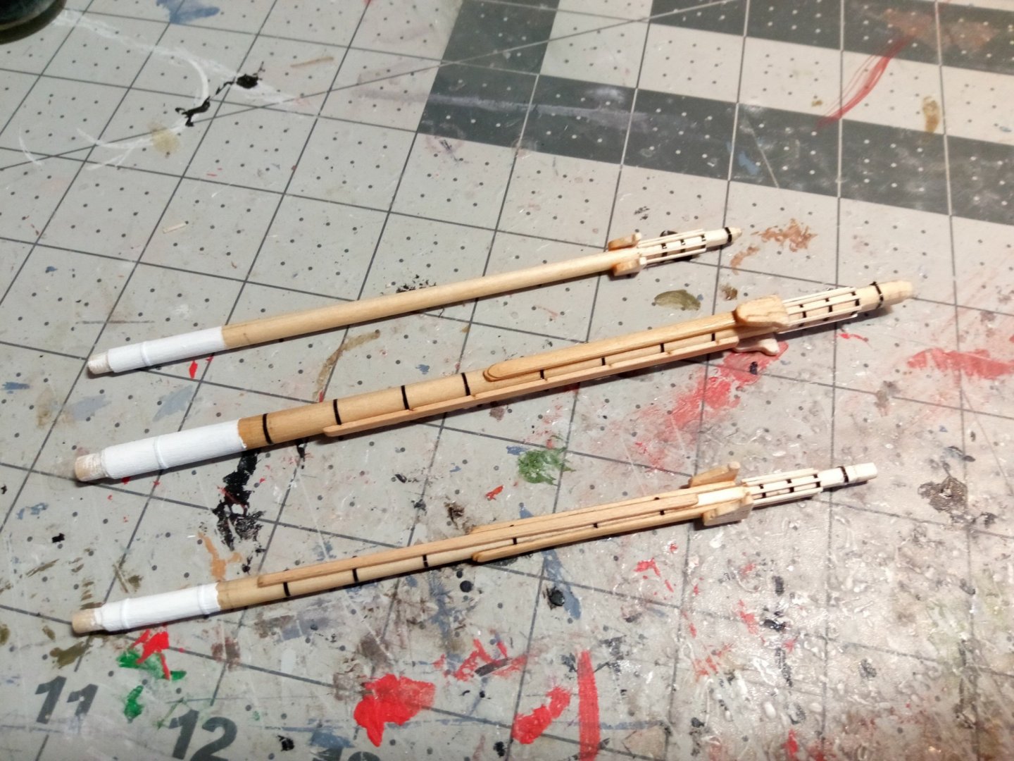
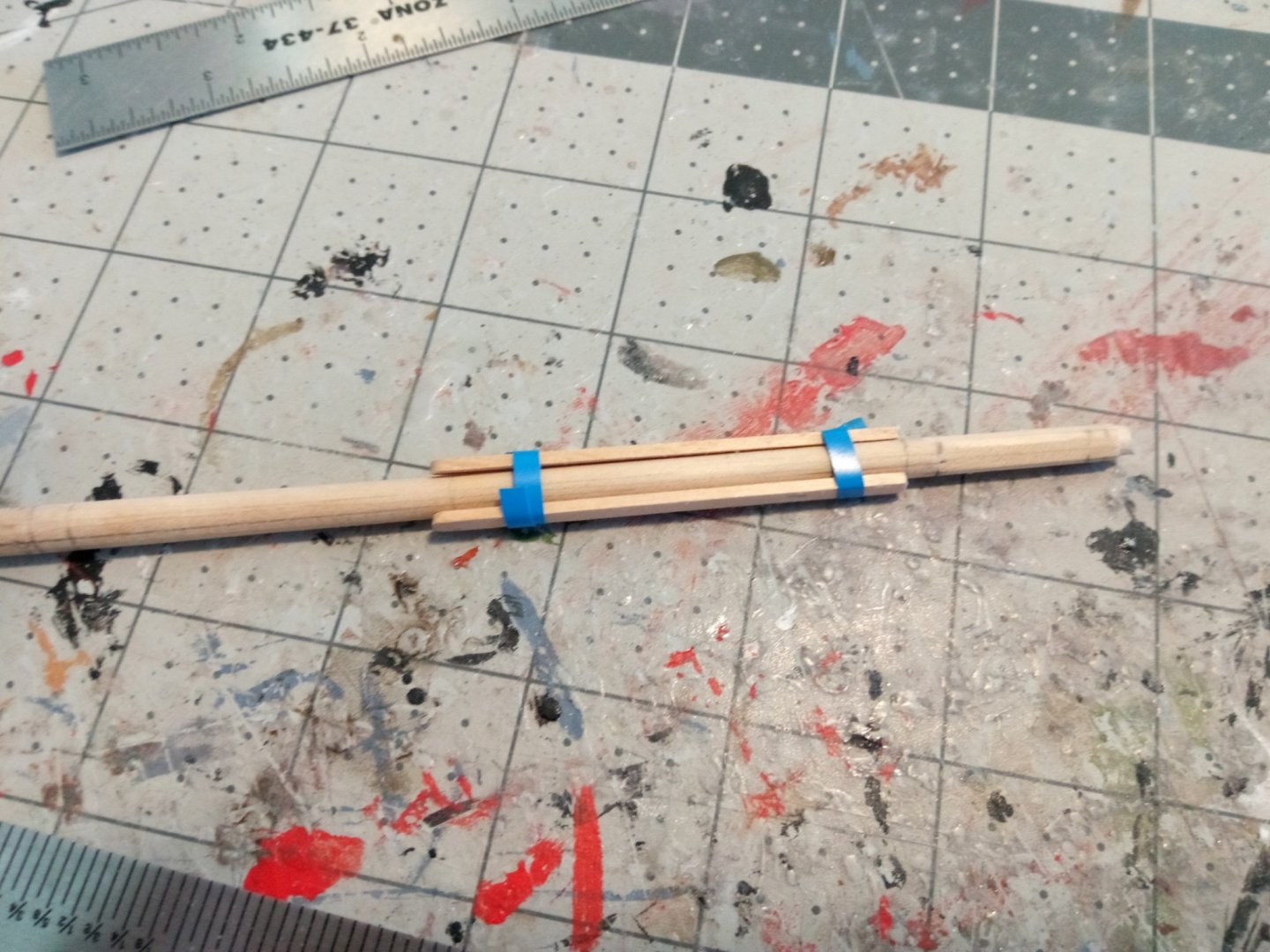
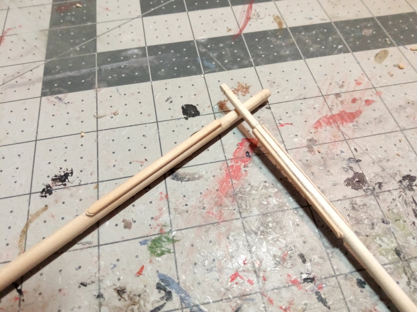
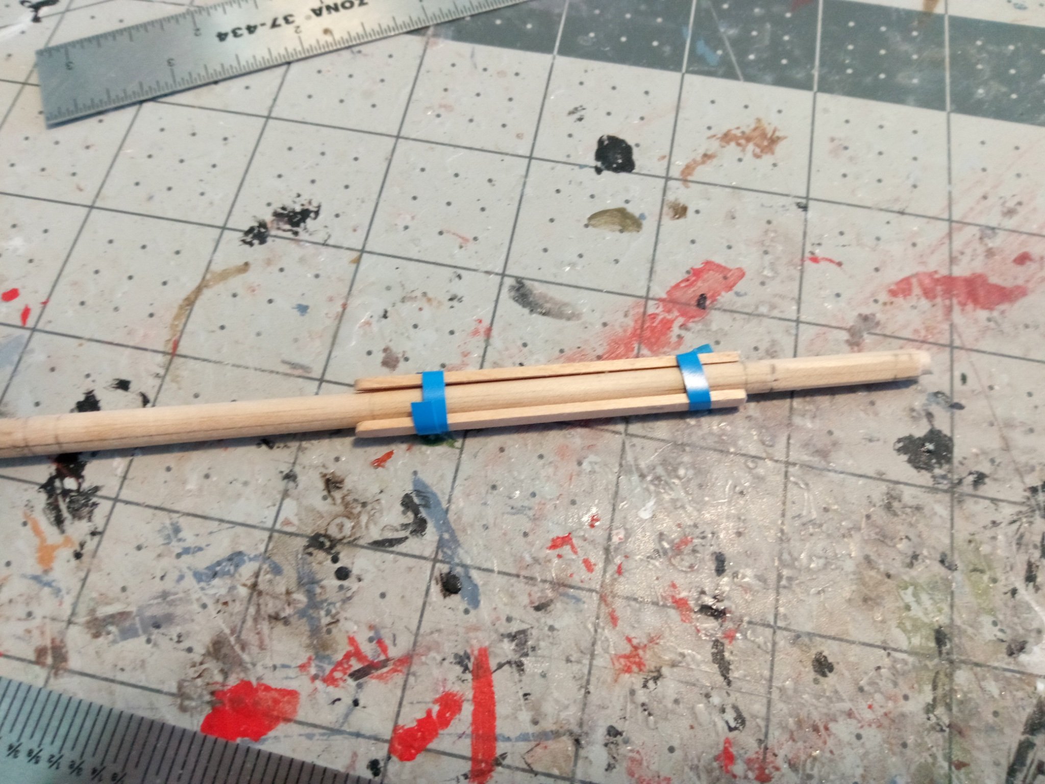
The cheeks were fashioned out of strip wood whose width matched the plans:
They were taped to the masts so that the profiles could be penciled onto the mast - that area was then filed flat so that the cheeks would sit flush on the mast:
Here are both masts with their cheeks. The cheeks have been sanded to about half of their original thickness and a “fingernail” profile was filed onto their lower ends (I have no idea what purpose that served):
The bibbs were traced from the plans and cut out from sheet wood. Although the foremast will be almost plumb the main mast does have enough rake to it that in order for the top to be level it will have so sit at a slight angle to the mast. The plans show a prominent joint were the bibbs on the fore and main were assembled so I’ve simulated that by scribing a line on the forward portion of the bibbs.
The next step was to add the iron bands around the mast using 2 sizes of pinstripe tape:
Next up will be the addition of some chocks and cleats and then the painting of the upper and bottom areas of each mast.
- Bill Morrison, sjanicki, KurtH and 2 others
-
 5
5
-
Lower Masts - Initial Shaping
This is a new area for me. The kit plans give a good depiction of the finished masts that can be used to get the final dimensions of the various pieces of the masts but the description of how to fabricate them is very general - some on what needs to be done but little on how to do it. I needed more than that so I went looking for some help. The following build logs here on MSW were very helpful with pictures and/or descriptions:
- USS Constitution by KHauptfuehrer, starting with post #19
- HMS Snake by Beef Wellington, starting on pg14
- Frigate Essex by Rafine, starting on post #1208
- US Brig Syren by Walrusguy, starting on post #688
I also relied on the instruction book for Model Expo’s US Brig SYREN kit (viewable online) which has some very good step by step instructions. If you use the SYREN instructions bear in mind that 1)SYREN did not have a mizzen mast - not a problem since ALFRED’s mizzen is just a simple version of her other masts 2) The SYREN kit is a different scale so disregard any mention of measurements, 3) the SYREN kit provides some laser-cut items that you will have to make from scratch for the ALFRED.
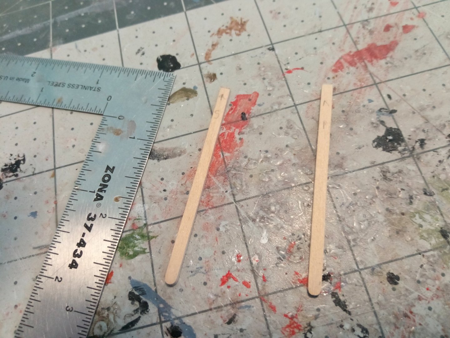
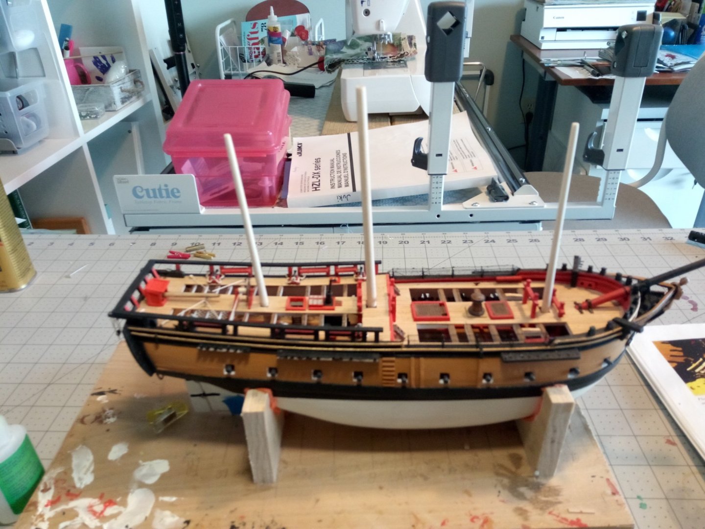
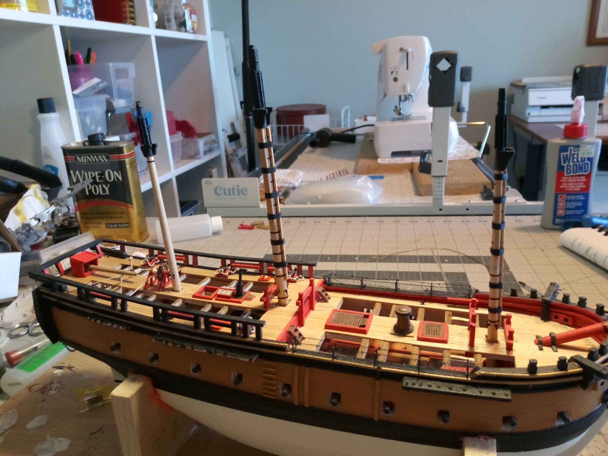
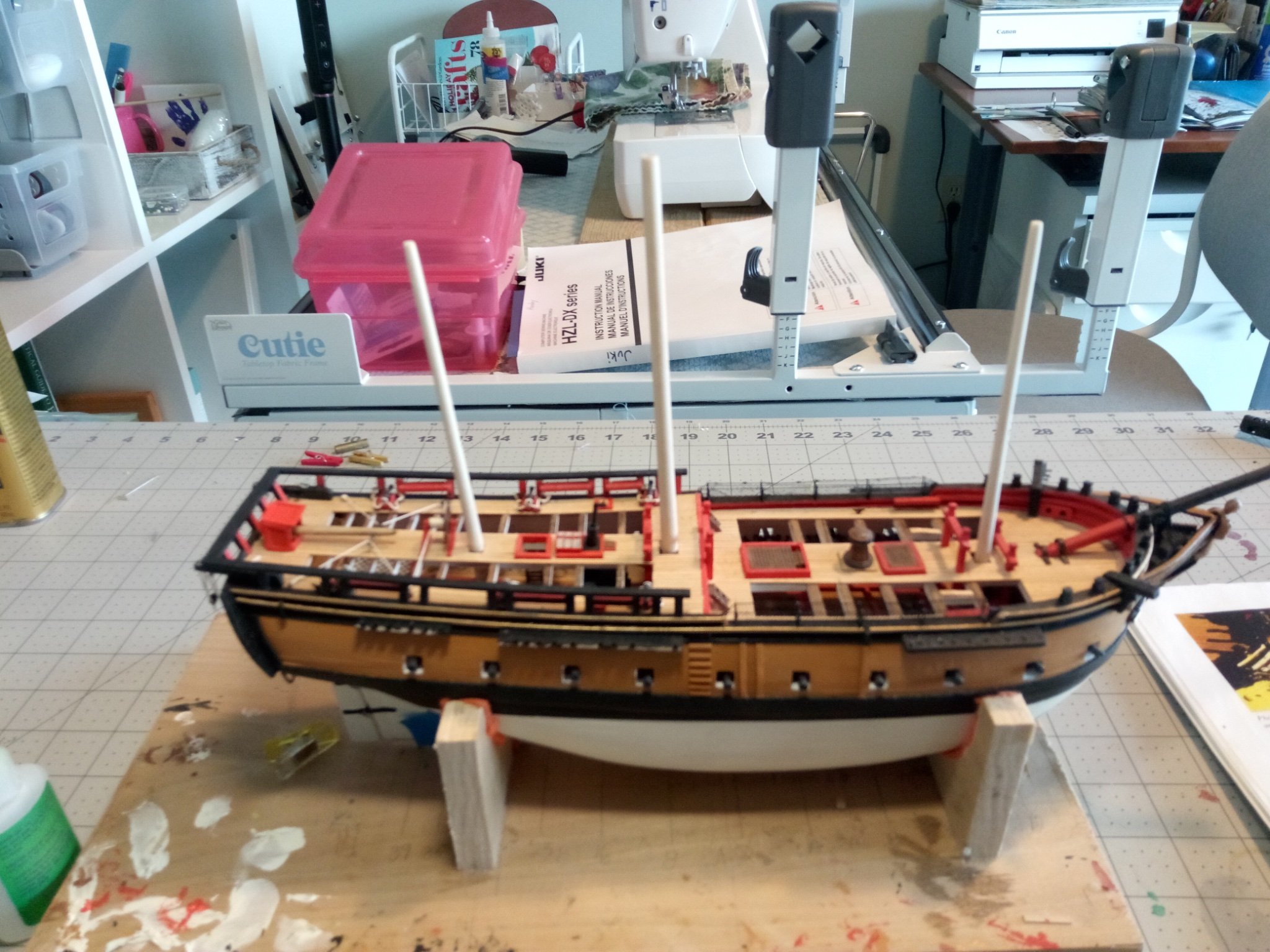
I cut the mast dowels to length per the plans. The width of the dowels below deck are an exact match for the mast widths so no tapering is needed, which is good because I already set the mast rakes using the dowels and mast partners and any tapering would throw those off:
I then tapered the above deck portions of the masts using my poor man’s lathe i.e. the dowel was chucked up in a power drill and sandpaper was used to run back and forth along the spinning dowel until the desired dimensions were achieved.
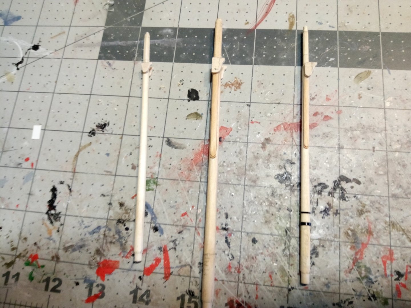
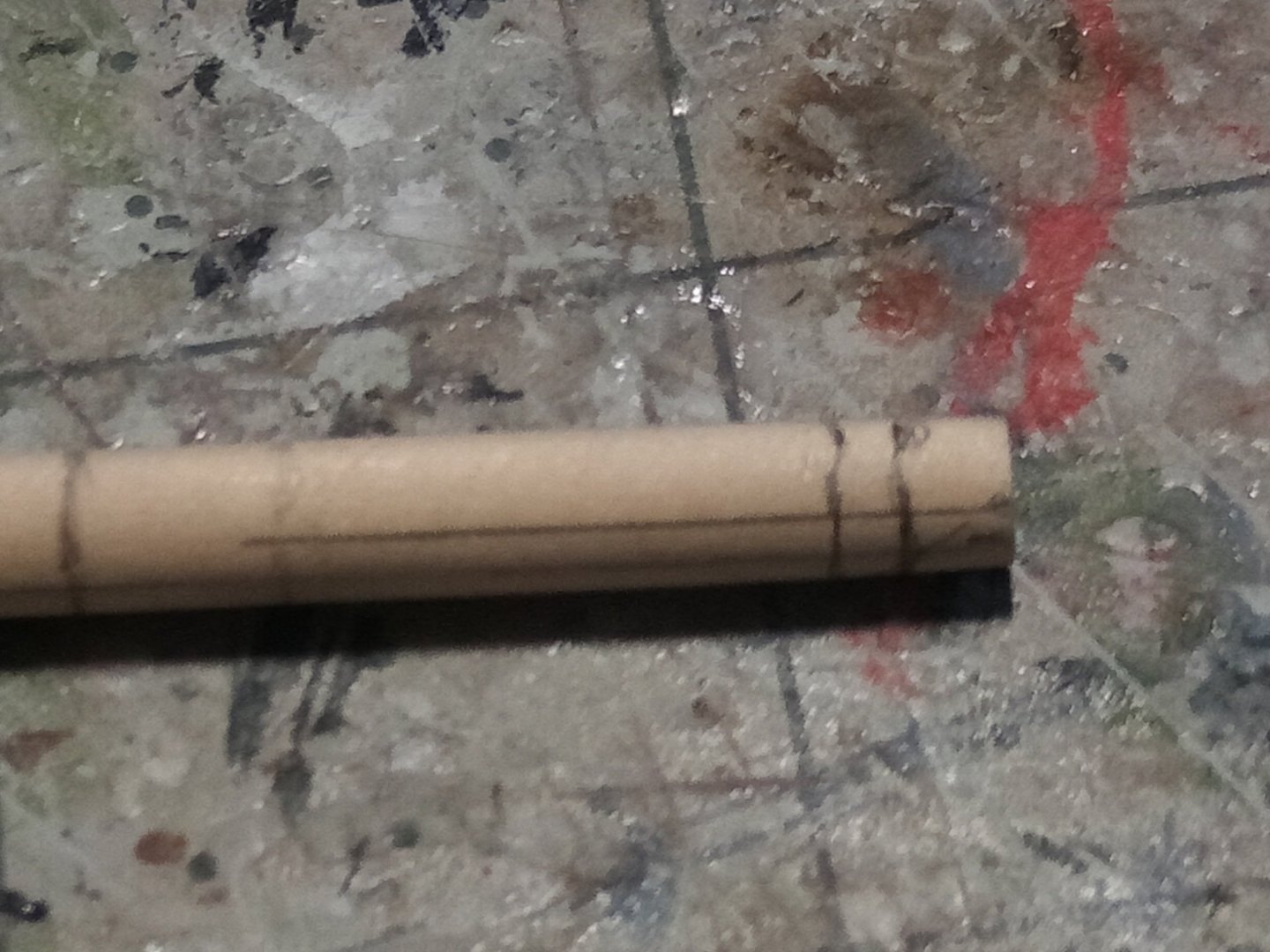
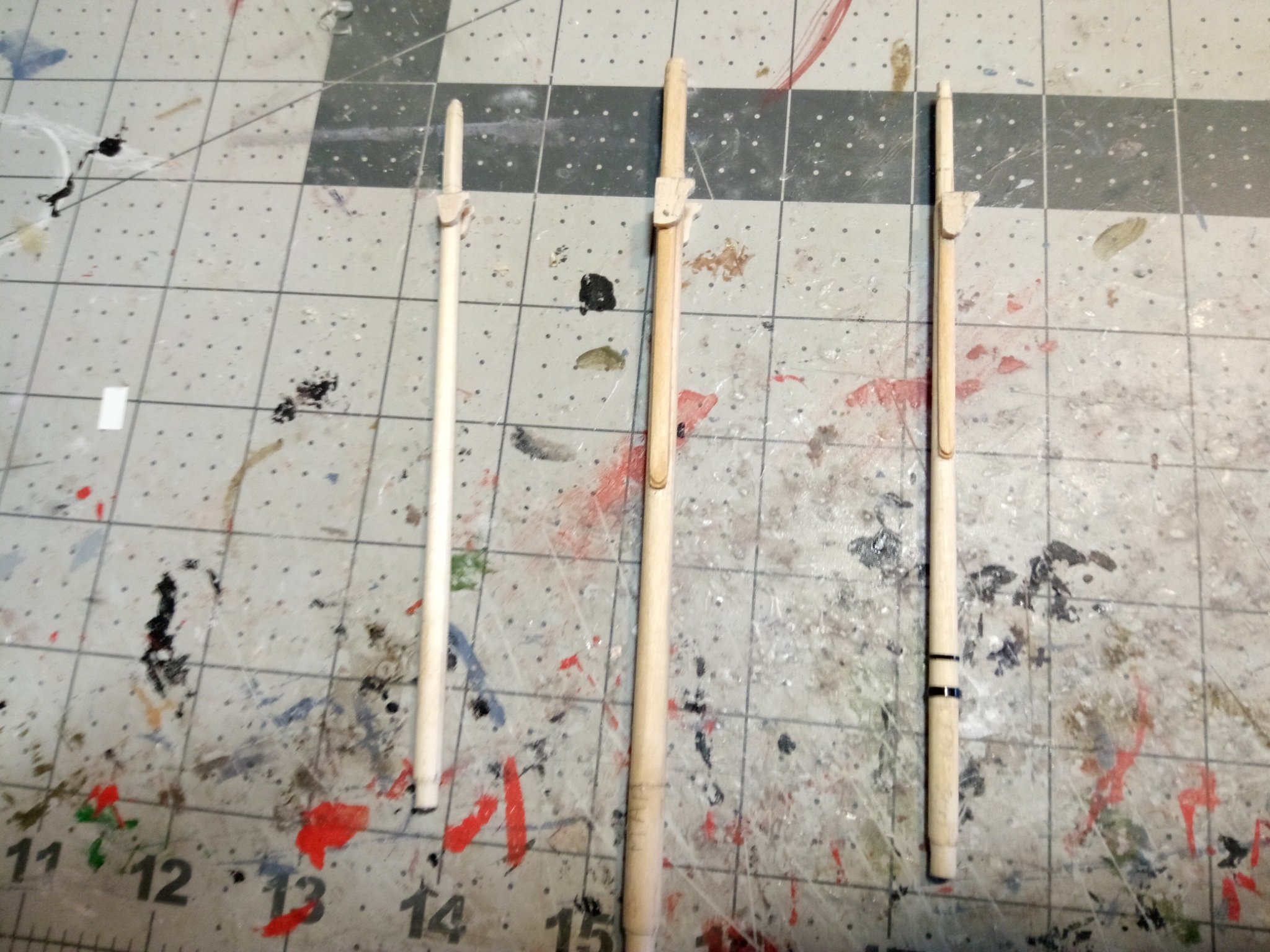
The next step is to square off the upper portion of the masts. I marked the largest square I could fit onto the top of each mast. Where the corner of each square touched the sides of the dowel I penciled a line parallel to the axis, down as far as the squared section would run:
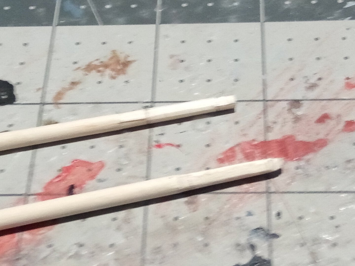
The initial cuts were made with a sharp exacto knife to get a flat surface on all 4 sides and then a file was used to expand the flat areas until everything was square. The final step in the squaring process was to file chamfered edges into the middle portions of each sharp edge. In this photo the lower mast has been squared and the upper squared and chamfered:
Next up will be shaping and installing the checks on the fore and main masts (the mizzen doesn’t have them).
- mort stoll, whitejamest, KurtH and 1 other
-
4
-
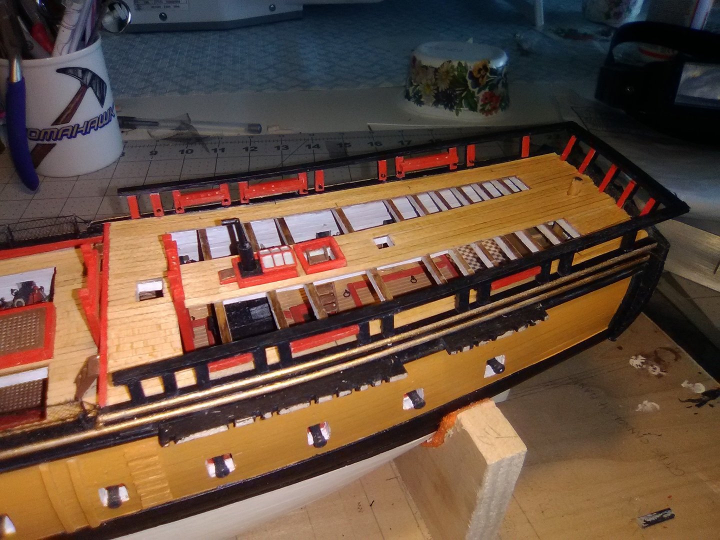
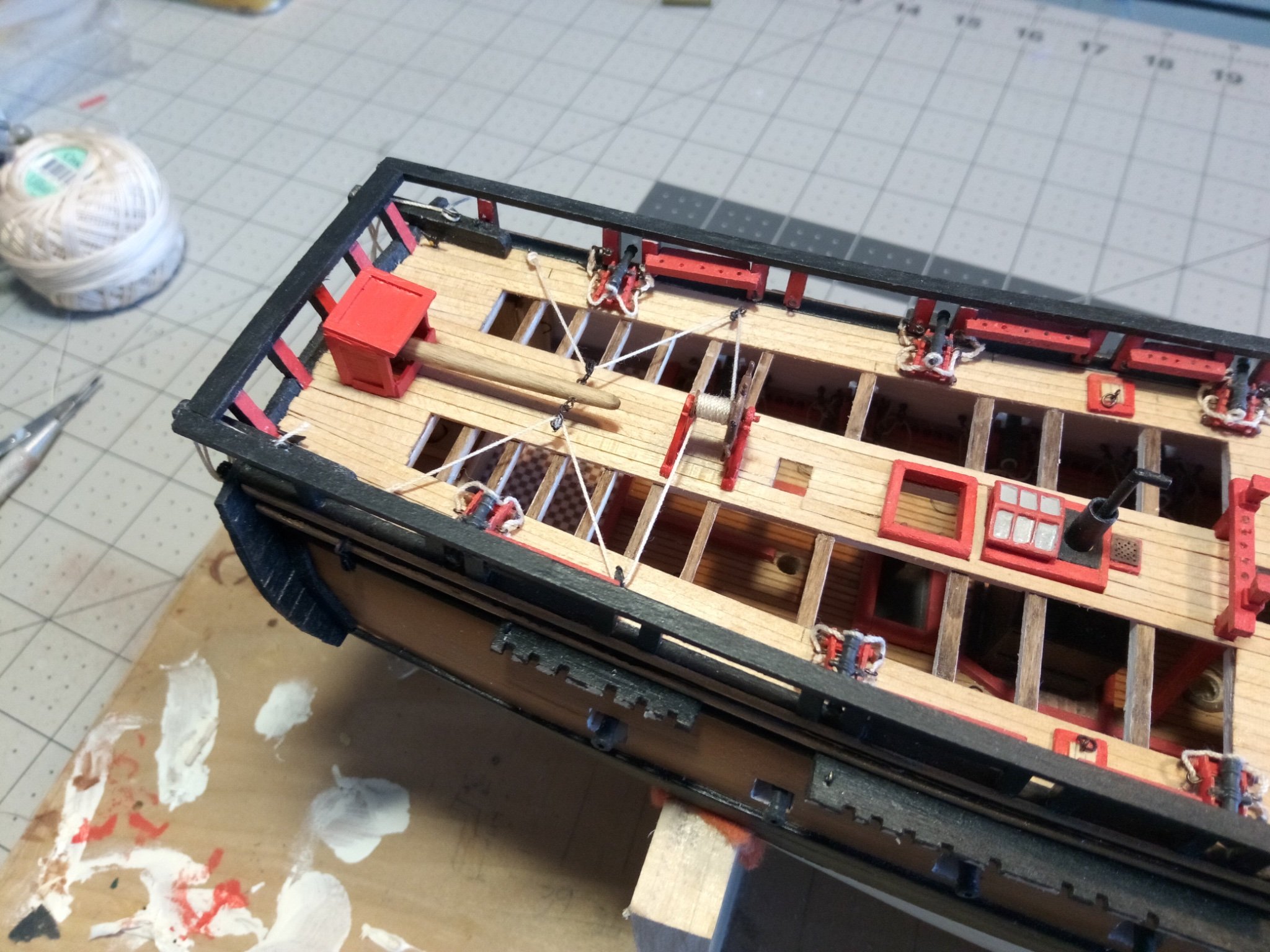
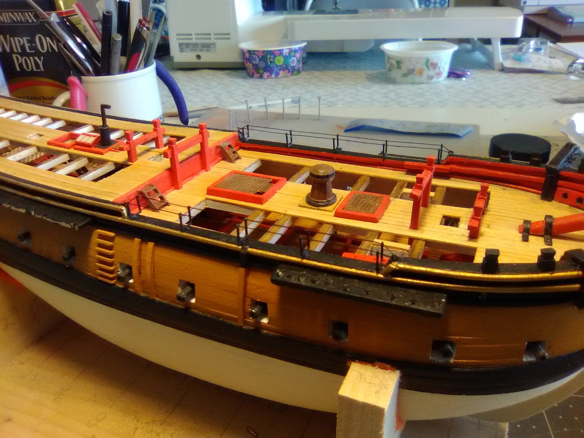
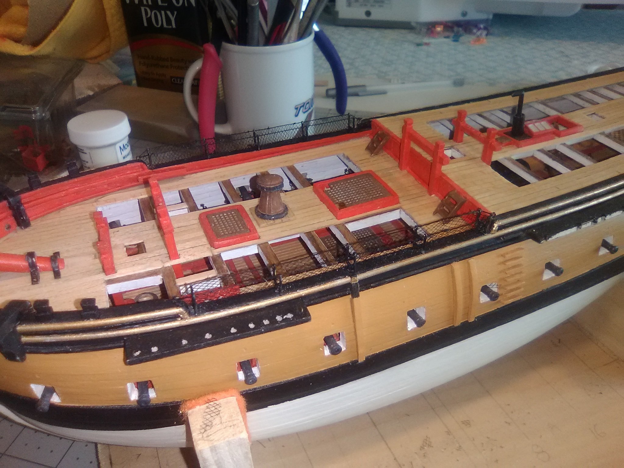
Final hull details
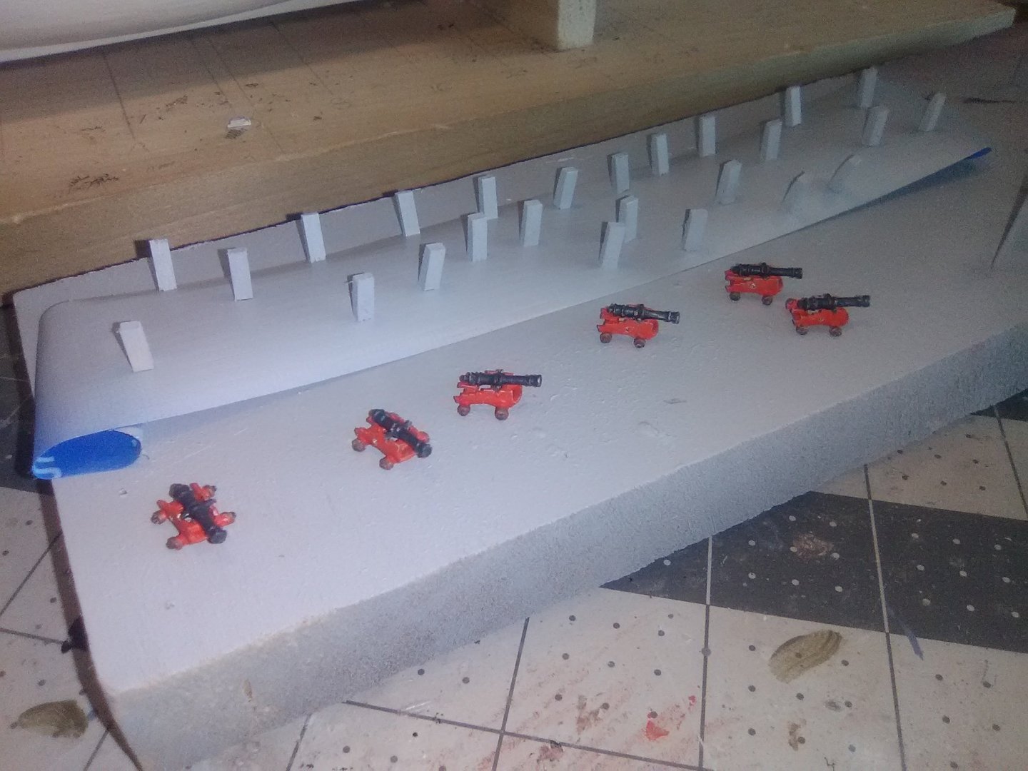
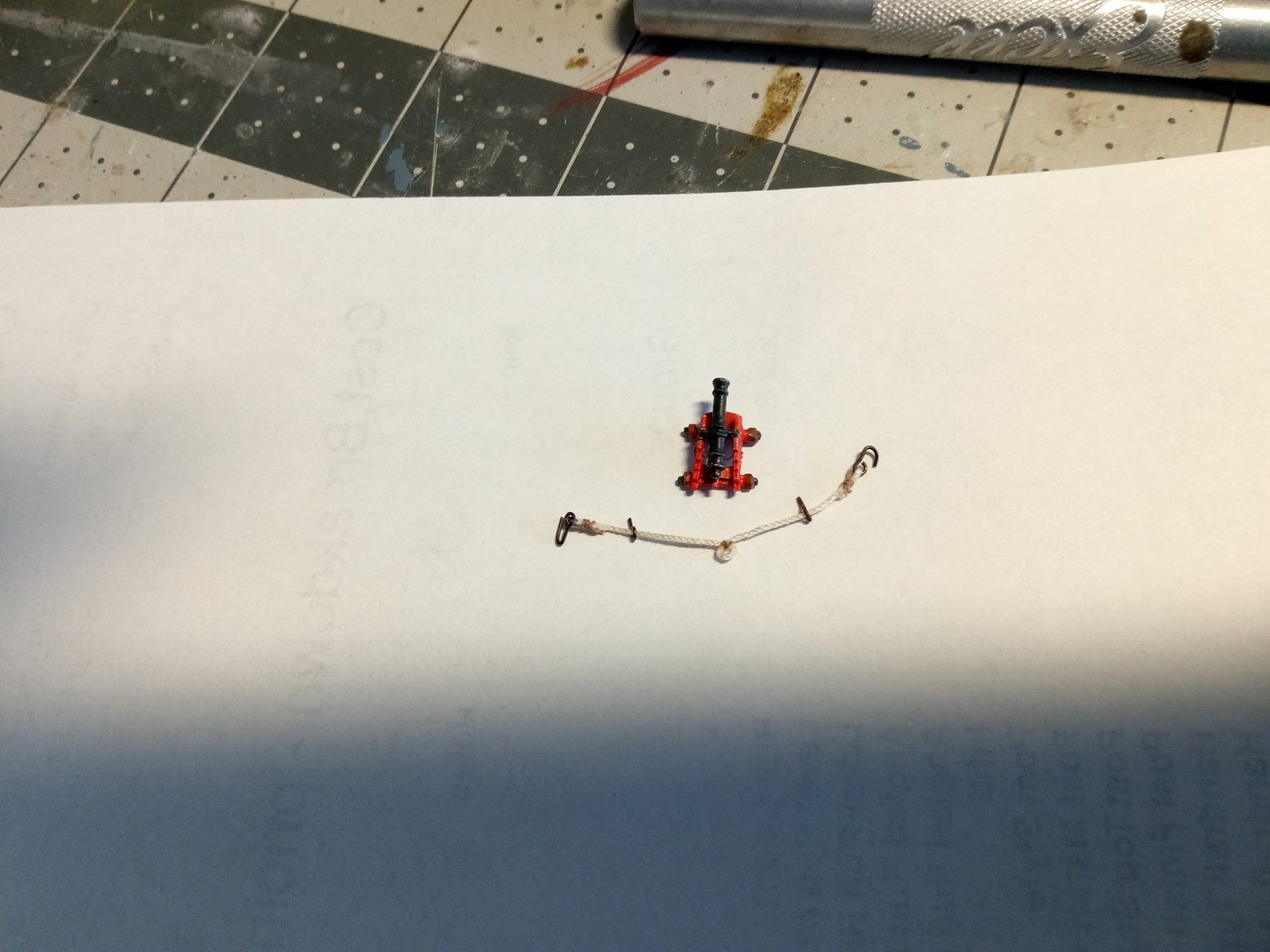
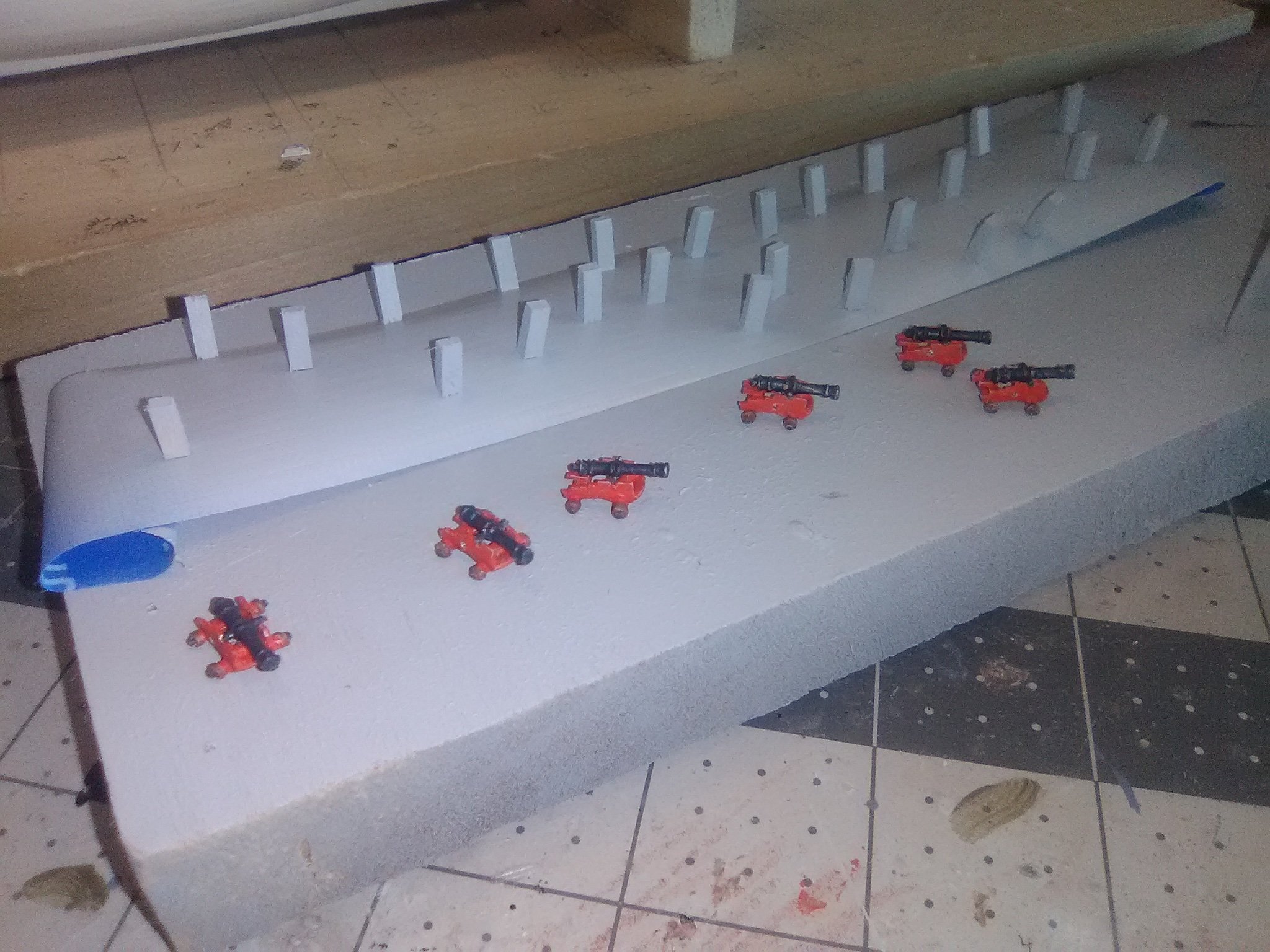
There are 6 4-pounder guns on the quarter deck, made up of 4 britannia metal pieces each. They are really small - the instructions said they were likely moved around where needed. I’m guessing that their small size meant they only needed breeching lines and that their in and outhaul movements could be handled with hand spikes or pry bars. Anyway, they are too small for me to attempt to rig blocks and tackles.
I used a simple jig to rig up the breeching lines.
Here the guns are in place, along with an ammunition scuttle on each side.
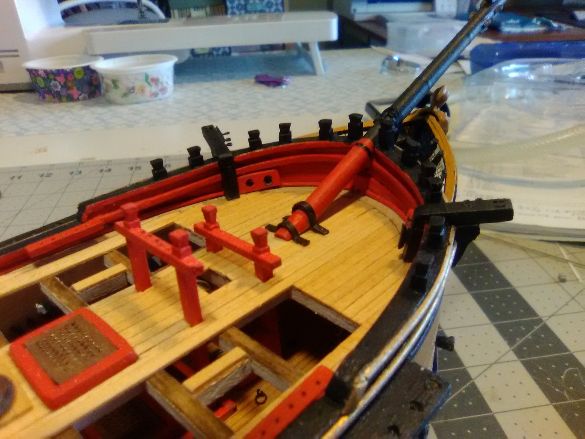
The tiller and it’s “doghouse” have been fitted, along with the ship’s wheel. The kit provides 2 britannia binnacles to be placed in front of the wheel but I’ll leave those off until all the deck rigging associated with the mizzen mast is in place.
Here’s the steering rigging in place:

This basically completes all the structural work on the hull except for the gunport lids which I will put on at the end of the build (so I won’t keep knocking them off) and the anchor windlass which goes on the main deck after the rigging is done.
Next up will be fabricating the masts and spars.
- whitejamest, yvesvidal, mort stoll and 5 others
-
8
-
I agree on Mort on using the instructions that came with the hull, although the new one might help with it's photos in some places. I don't know what your version calls for but mine calls for opening up the gun deck and then after the guns are in place covering everything back up with decking so you would not really be able to tell it's open down there (the big openings in my decks are my addition).
I'm happy to answer questions and give advice but please keep in mind I don't have your older version of the instructions and plans.
Go slow, think thrice, measure twice, think again and then cut once. Have fun.
BTW, although I have not posted in awhile, I still slowly working and post something soon.
- mort stoll, Bill Morrison and mtaylor
-
3
-
-
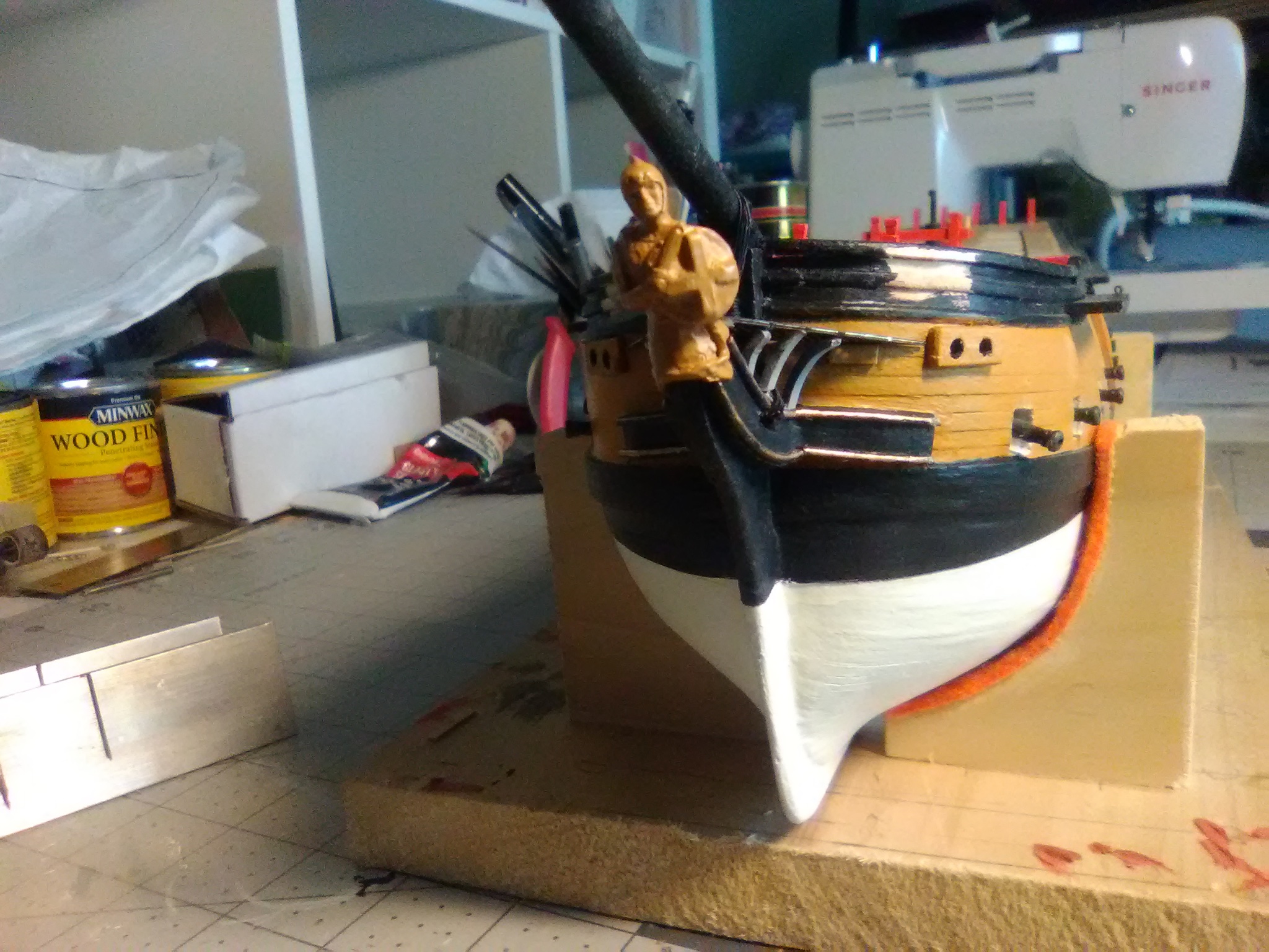
Hi Susan,
That "big bulb" of wood at the bow is the leftovers from when the hull was machined, most solid wood hulls have them, and usually another at the stern. Once you are used to shaping solid hulls you can usually sand those "bulbs" off quickly with a rotary tool.
- pwog, Kevin and EatMoreLobster
-
3
-
-
-
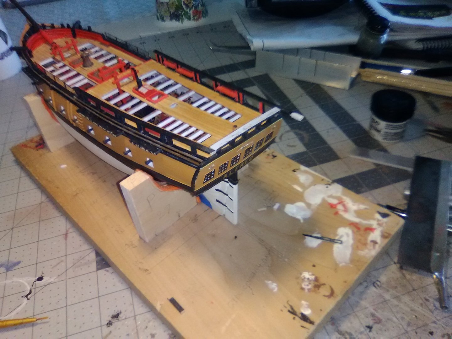
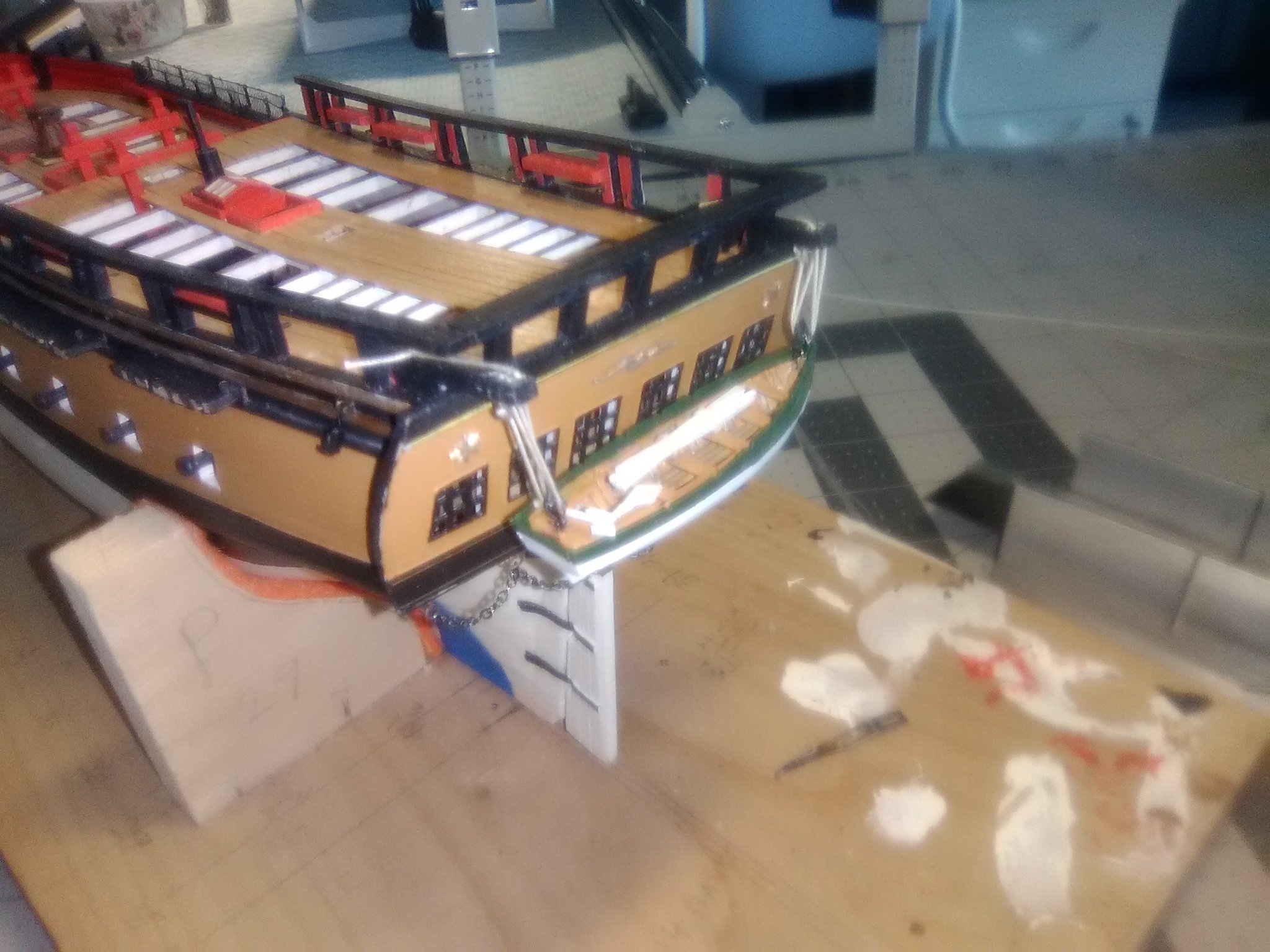
Transom details
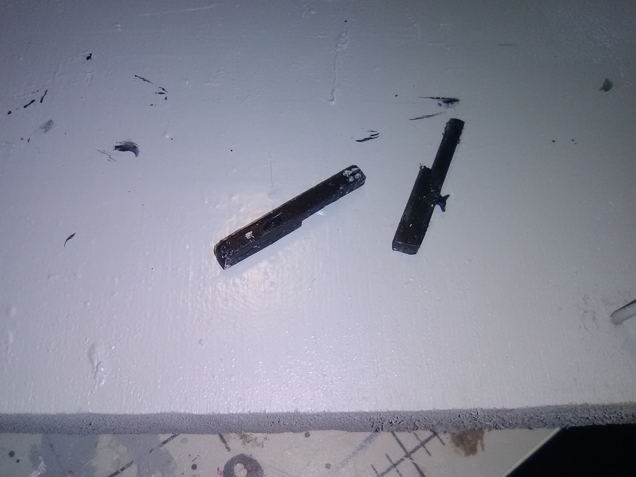
The stern davits were made out of 2 pieces of strip wood “stepped” above each other so they could pass over the 1/16” lip or edge on the transom piece. Once installed 4 holes where drilled near their outboard ends to simulate sheaves.

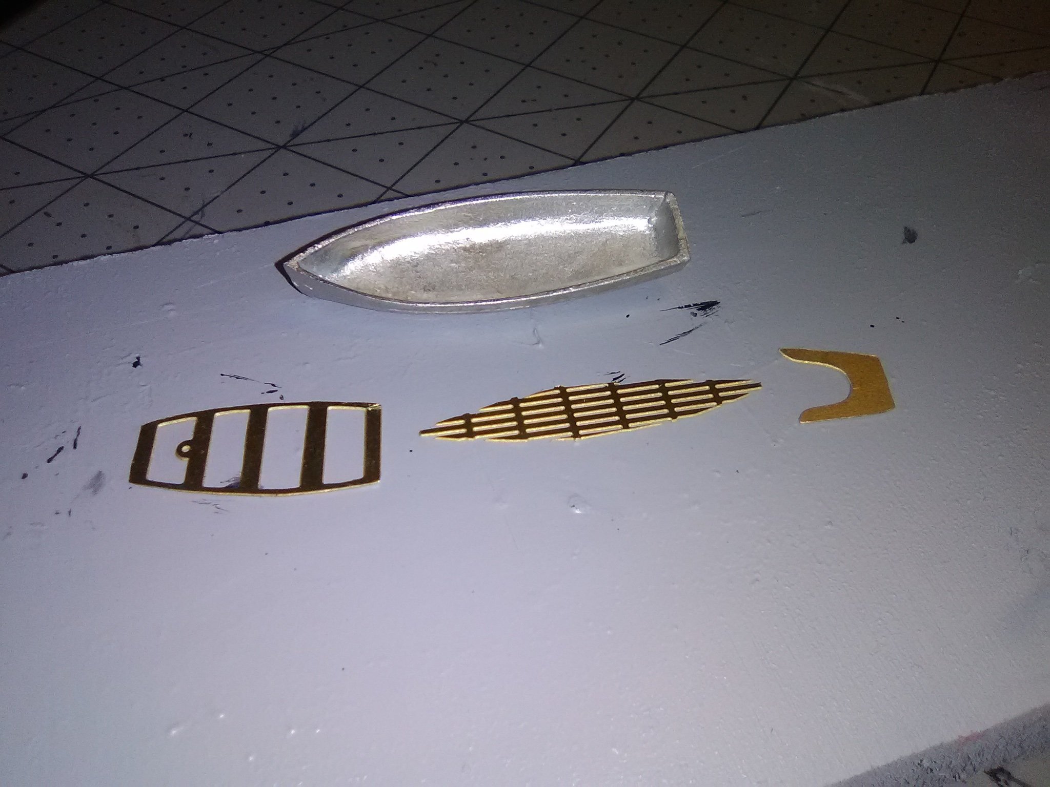
I was originally going to leave the stern mounted boat off and show the larger longboat on the main deck but after all the work involved in putting in the deck reveals it didn’t make much sense to cover up half of them with a boat. So I decided to put together the smaller boat - I may still do the larger water and either mount is on the display board or show it suspended from the yard whips as it would be during launch or recovery.
The kit provides a britannia hull and 3 pieces of photo etch:
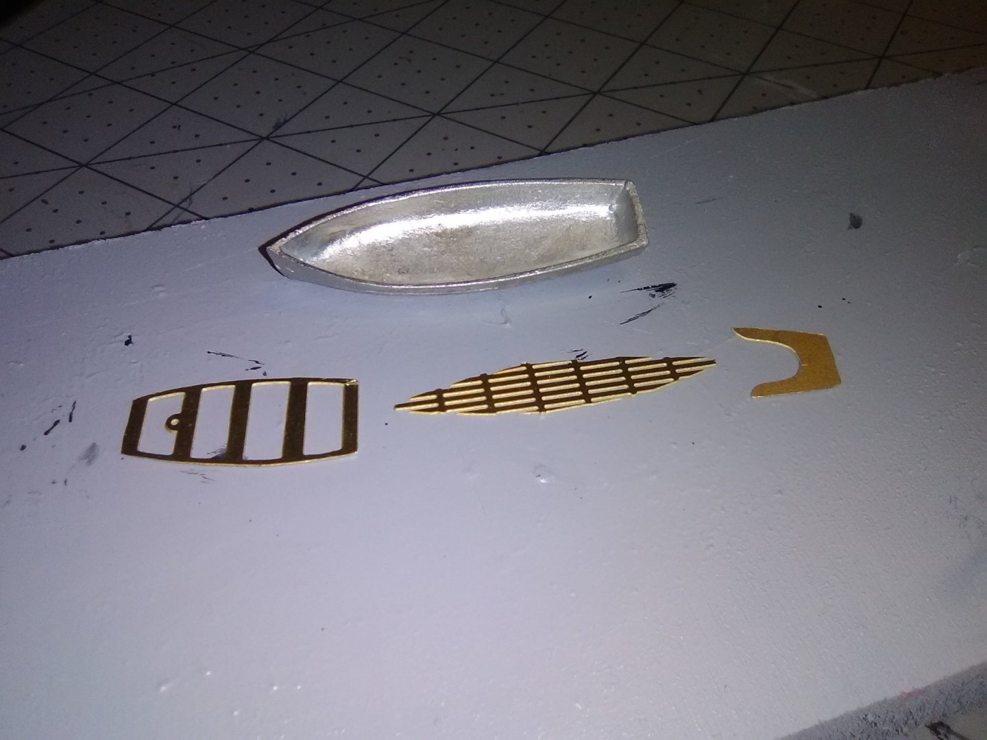
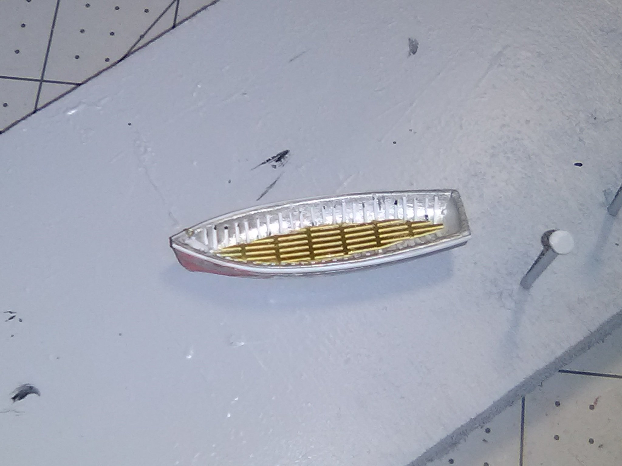
I decided to add a little detail by using strip plastic for the frames, and raising and thickening the gunwales:
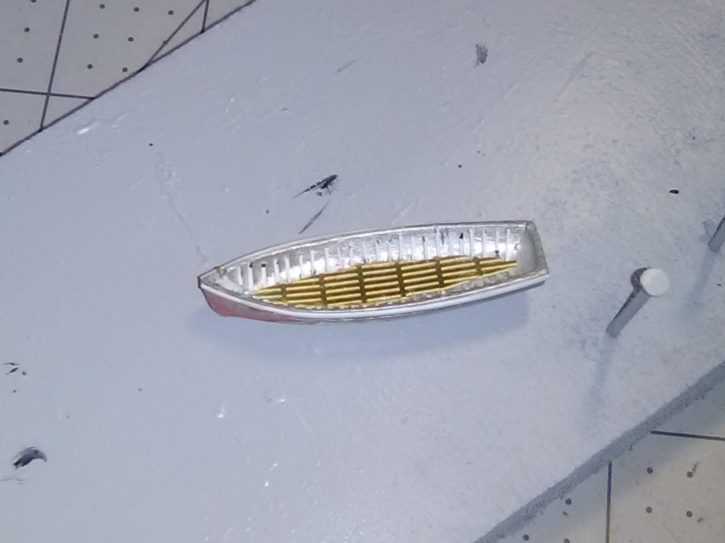
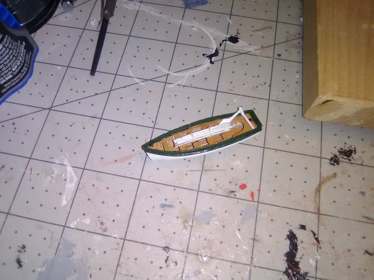
The finished boat is shown on the davits, and as you can see I also added the rudder pendants:

-
-
-
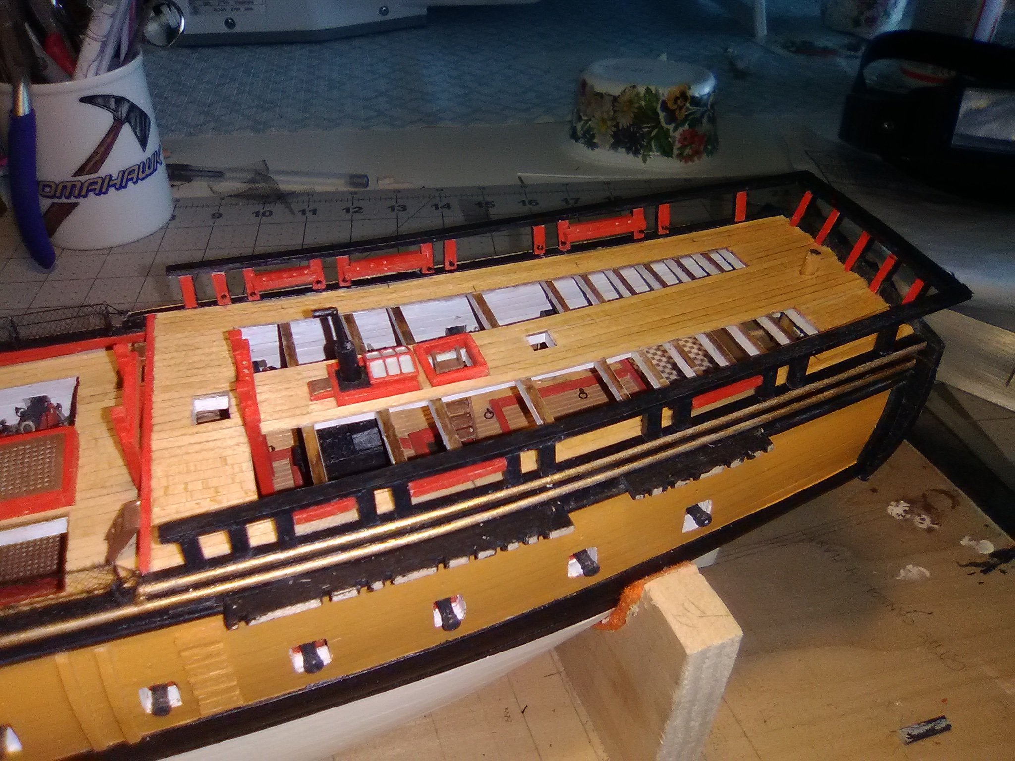
Quarterdeck and Taff rails
The rail stanchions were cut using a “Chopper” from Micro-Mark which gave me more consistent lengths than I can get with a hand saw. The directions call for tapering the 3/32” square stock to 1/16” at their upper ends but it does not say whether that is 1/32 off of one side or 1/64 off of opposite sides. Since trying to taper 1/64 is beyond my interest level I took off 1/32 on the inward faces (its too small to notice so that step can be skipped)

Then instructions state that open railings like this were a common feature on colonial era ships but since the rails were not strong enough to tie off lines to they had to use pin rails so 6 of those have been added

Here’s the railings in place (left long on the aft end to fit in with the taff rail)
And here is the final product.
Next up will be the stern davits.
- GrandpaPhil, Marcus.K., KurtH and 3 others
-
6
-
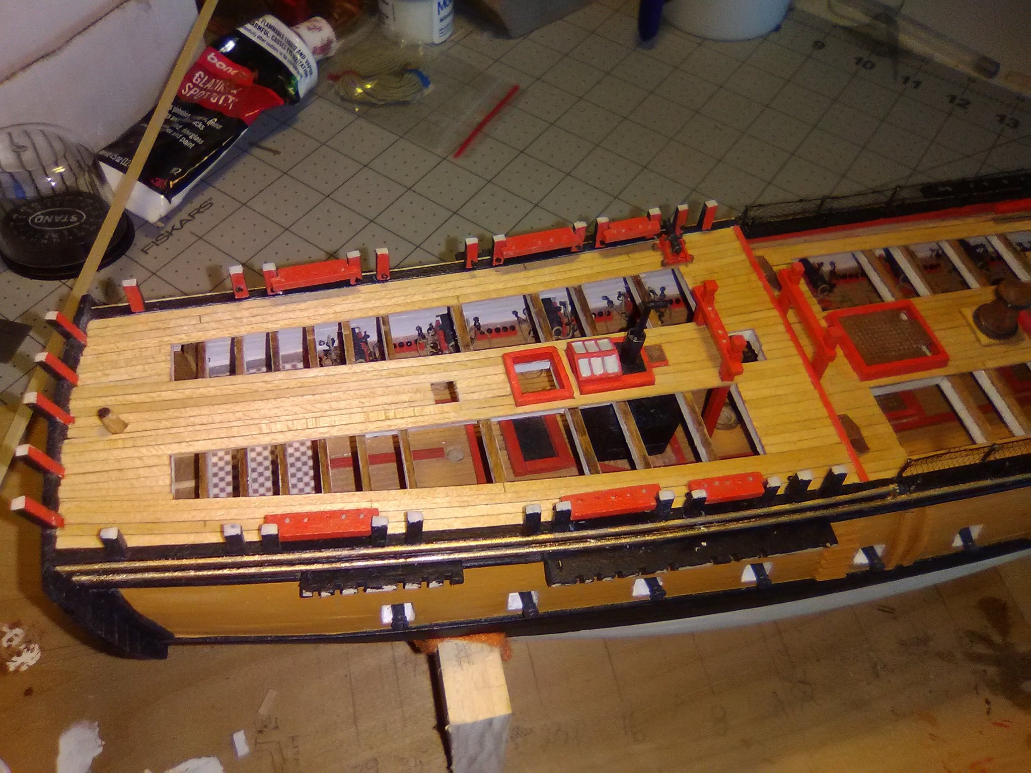
Hammock Netting and the start of the Quarter Deck Railings
Modelling time has been a little hard to come by lately so I have not made much progress. The Hammock netting cranes are made up from PE. The instructions call for connecting them with wire but I found that black thread worked better for me.
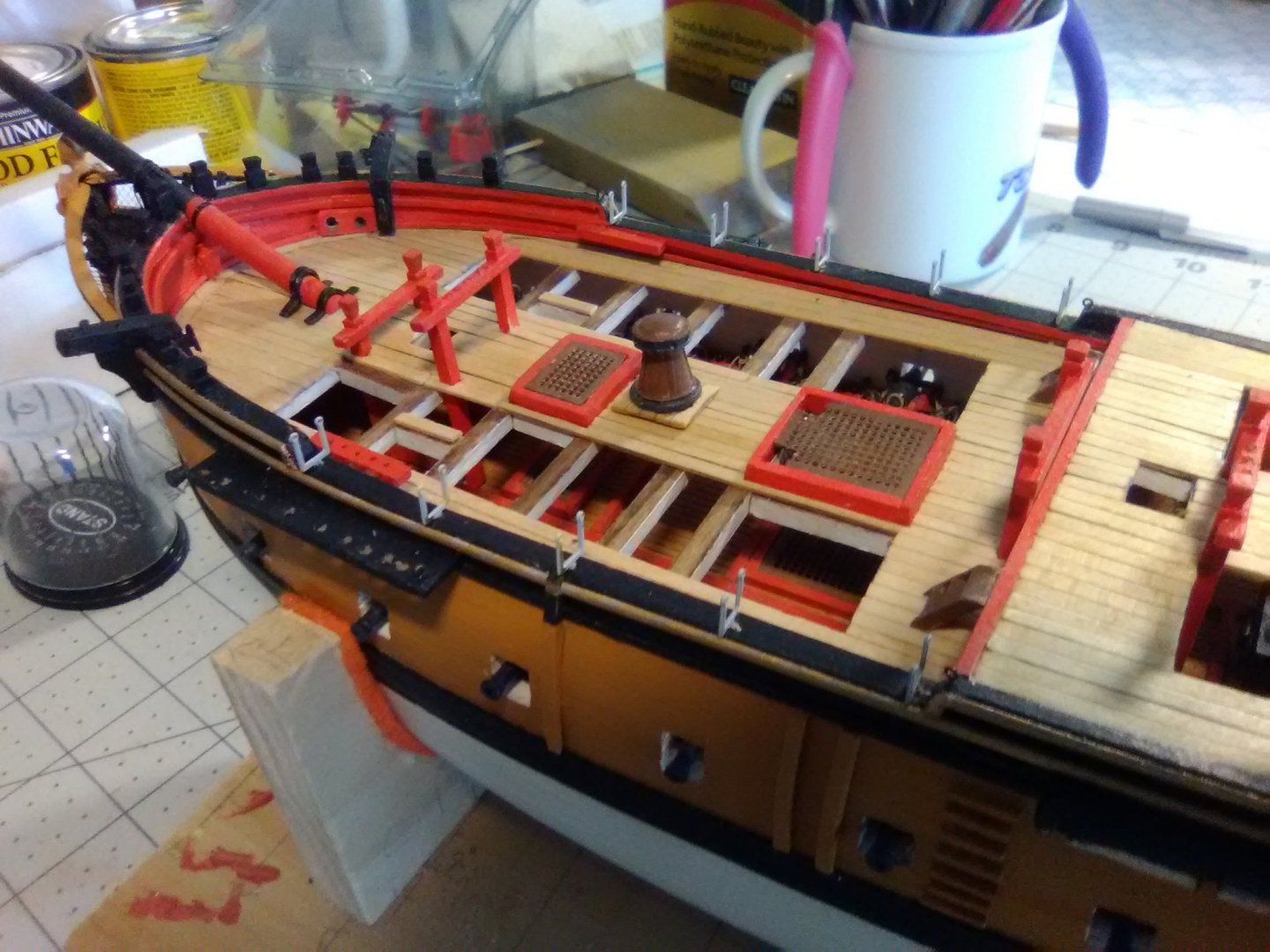

The netting was easy to install as long as a piece of white paper was placed behind it while trimming or it would have been a real strain to figure out what I was doing.
The plans call for making 24 stanchions for the quarterdeck railing but the plans only show 22. I made 24 anyway because I’m going to put 1 extra on each side just forward of the taffrail so as to avoid a 9 ft gap without a stanchion. I made up the 4 pounder guns so that I can figure out how high to place the rings on the stanchions for the breeching lines.
- GrandpaPhil, cdrusn89, KurtH and 5 others
-
8
-
-
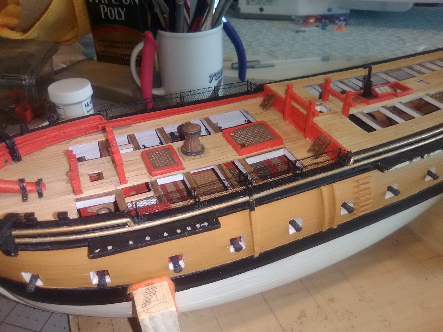
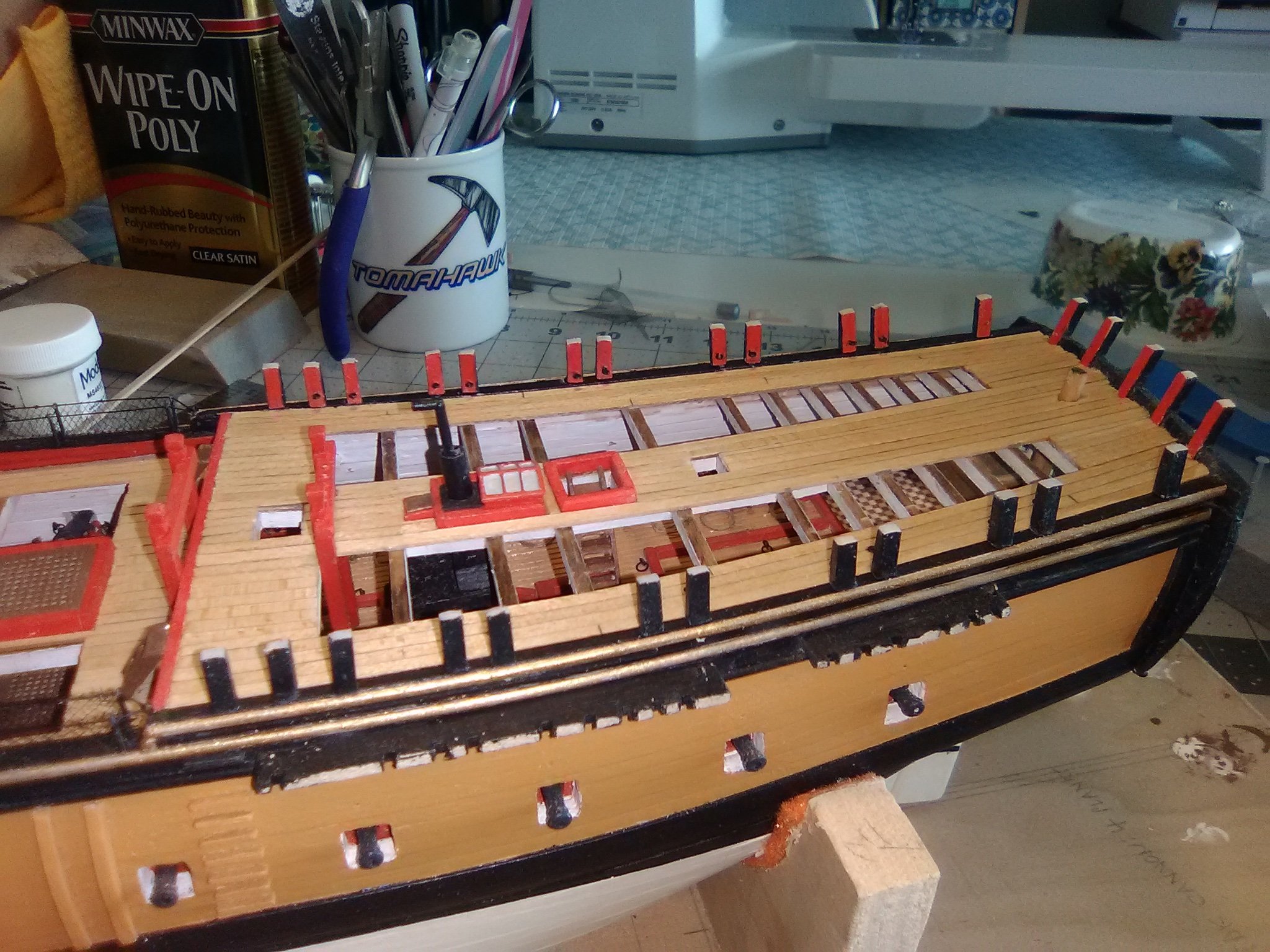
Knightheads and Timberheads
I’ve made very little progress lately because of outside distractions.
The next step in the build is to fabricate and install the main deck pinrails, knight heads and timber heads. They were easy to shape out of the supplied strip wood. Instead of using the plans for their placement I used the belaying diagram in the instruction book which gave a better view of their spacing:

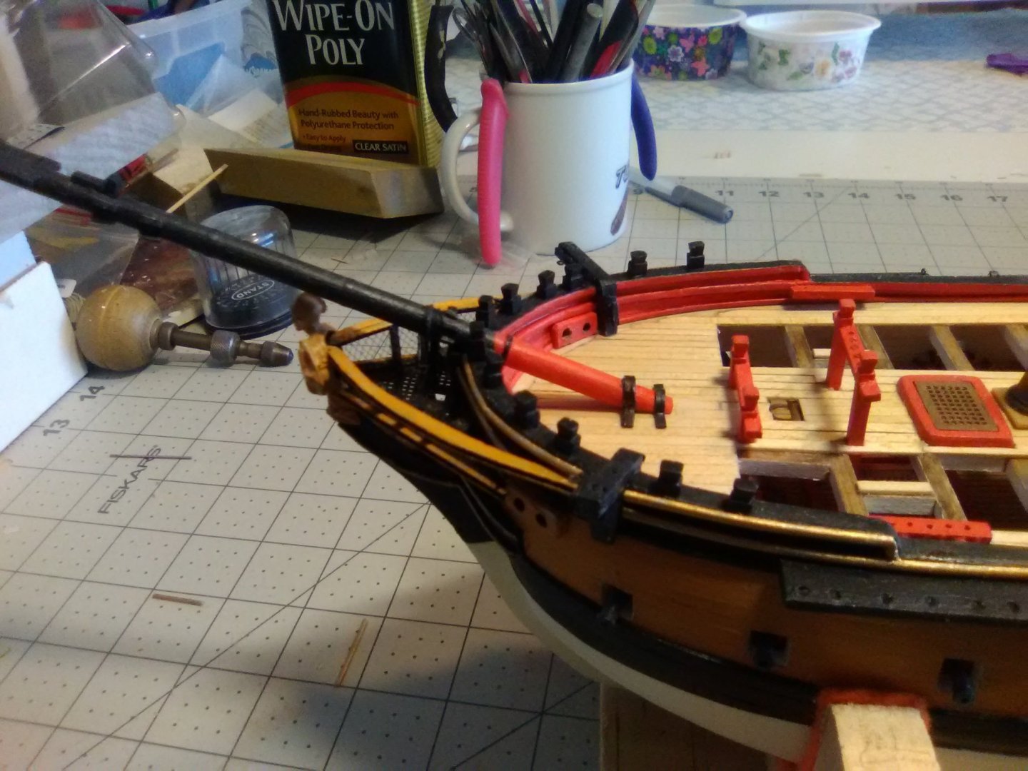
Next up will be the hammock cranes along the lower part of the bulwarks
- KurtH, Bill Morrison, cdrusn89 and 2 others
-
5
-
Tom,
This is a really interesting kit and your quality of work is excellent!
I was interested to see that the kit provides detailed deck framing. Have you considered leaving off the main deck planking on one side (the side away from the viewers would be best) from the centerline to the waterway so all that detail (and some of the berth deck details) could be visible?
Keep up the good work - I'm looking forward to the rest of this build.
-
-
Re-Do on the gilt trim
Although I did not mention it in my last post the photos show the gilt trim along the main and fancy rails. The instructions suggested using a paint pen, which I have never used before but I gave it a shot and to my aging eyes I thought it looked pretty darn good … until I saw the photos “blown up” here on the site, which makes my photos more “close-up” than they appear on my computer. Boy, it looked bad!! In retrospect it probably would have worked fine if I had made sure the surfaces were smooth and the edges sharp rather than rounded. Some tape probably would have helped too but at that point I probably would have just used regular paint.
So anyway, all that was sanded off and replaced with 1/16” half round strip from BlueJacket (their catalog lists it under “moulding strips”) that were primed and painted off the model. If I had to do it again I probably would have used the “double-bead” strips for the fancy rails for a little contrast. This is a big improvement over my first attempt.


Next up will be the knight heads and timber heads around the foc’sle.
- whitejamest, Bill Morrison, KurtH and 4 others
-
7
-
Very clever work on the volutes!
-
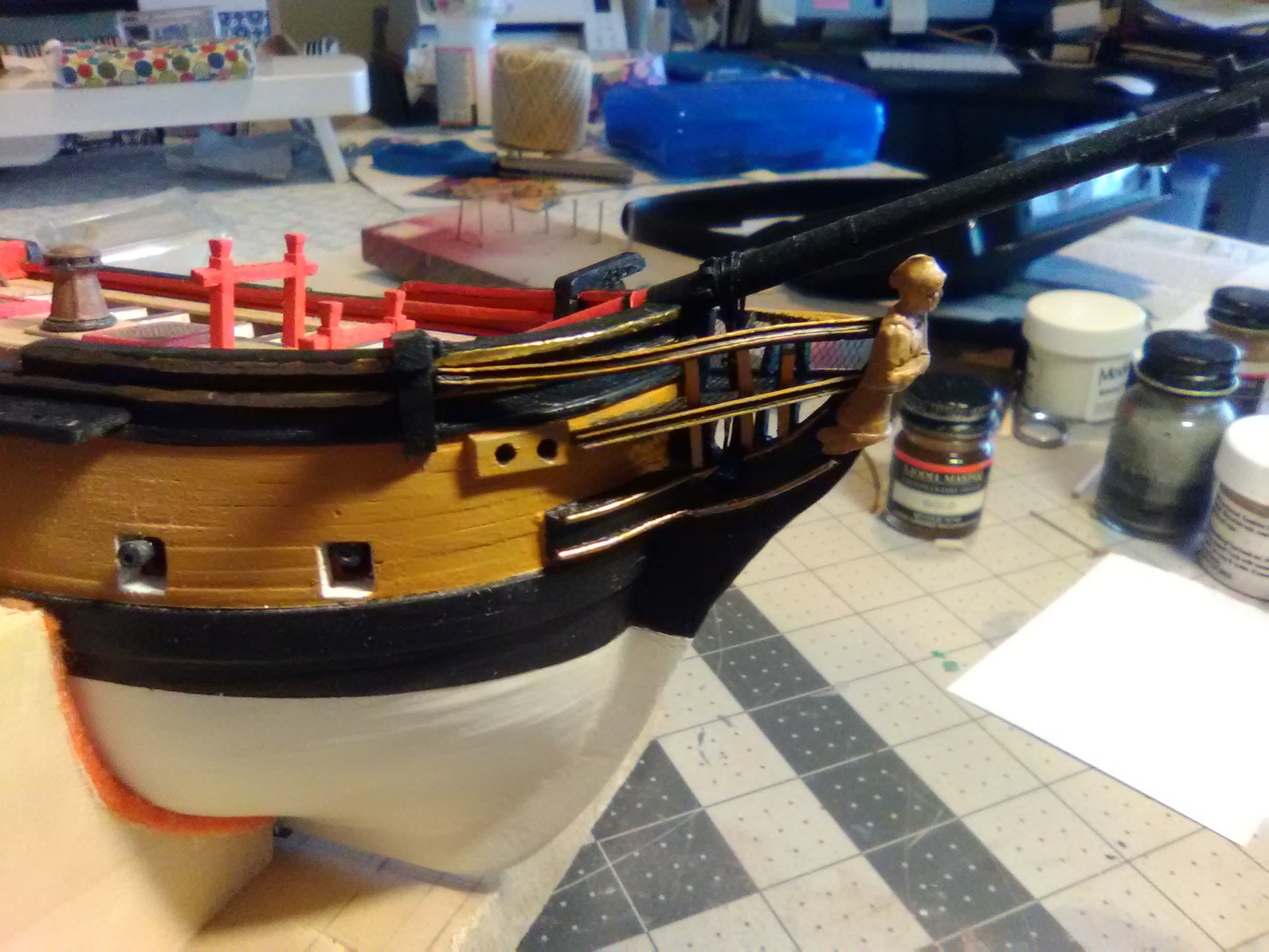
Finishing up the Head Rails
As I mentioned in an earlier post, britannia metal does not stand up to multiple bendings so I used a piece of wire to get the shape of the upper rails set:
I then transferred that shape to the britannia, attached the channel plastic to its outside face and put them in position. The support timbers that run vertically between the rails were easy to make out of britannia strip.

The final details were the netting and the 4 “seats of ease”:

- whitejamest, mort stoll, KurtH and 2 others
-
5
-
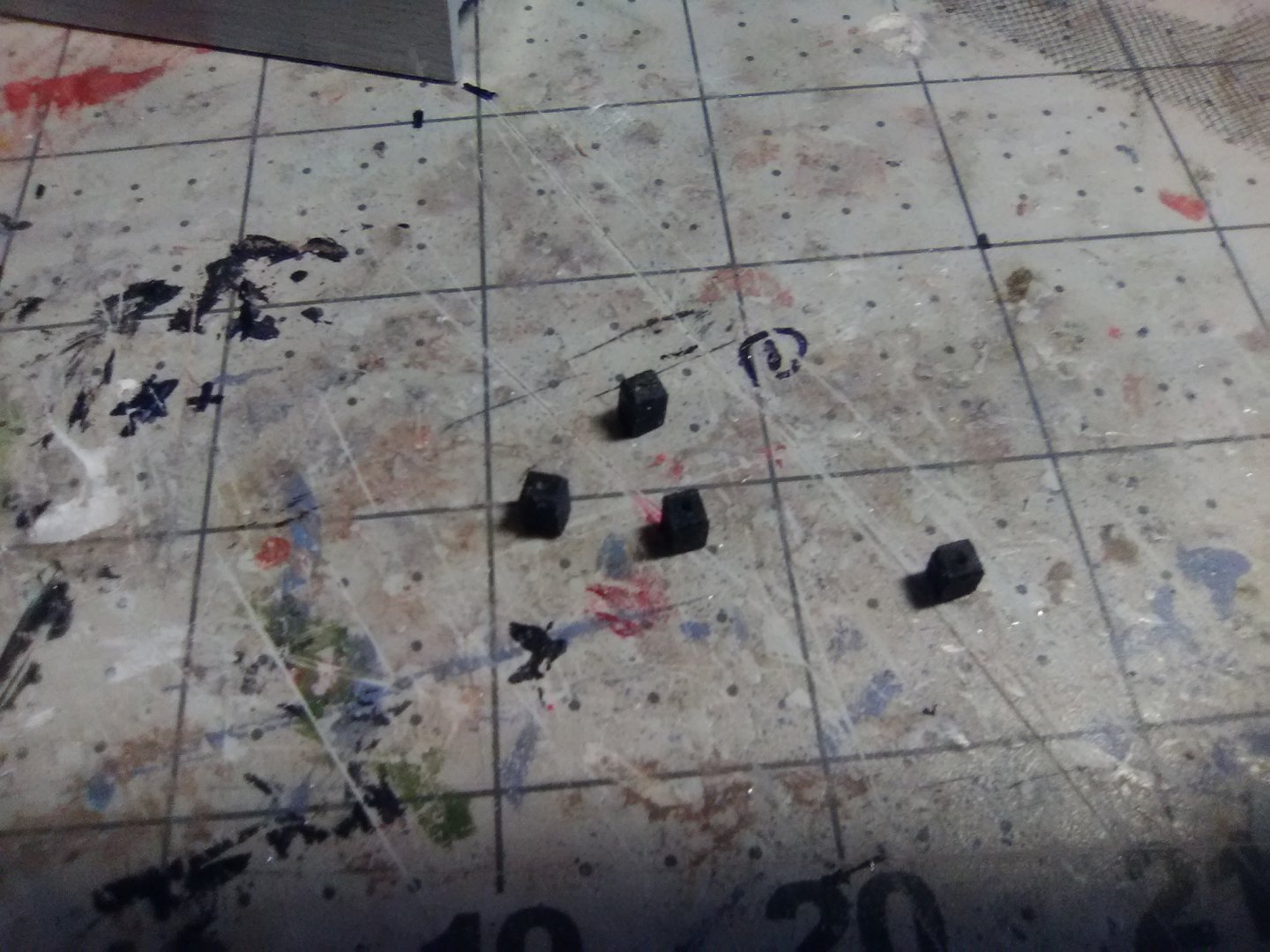
Catheads
The catheads were fabricated out of 1/8” square stock.
The inner piece had to be notched to fit over the main rail and the waterway.
The top piece has fake sheaves (2 pairs of holes, each pair linked with a “trench” connecting them). Plastic strip was used to make up the exterior sheave that will be used for the cathead stopper cable:

The knees under the catheads were made from 1/8” sheet. A piece of card stock was used as a template:

With these done I can resume work on the headrails.
- Bill Morrison, mort stoll and KurtH
-
3
-
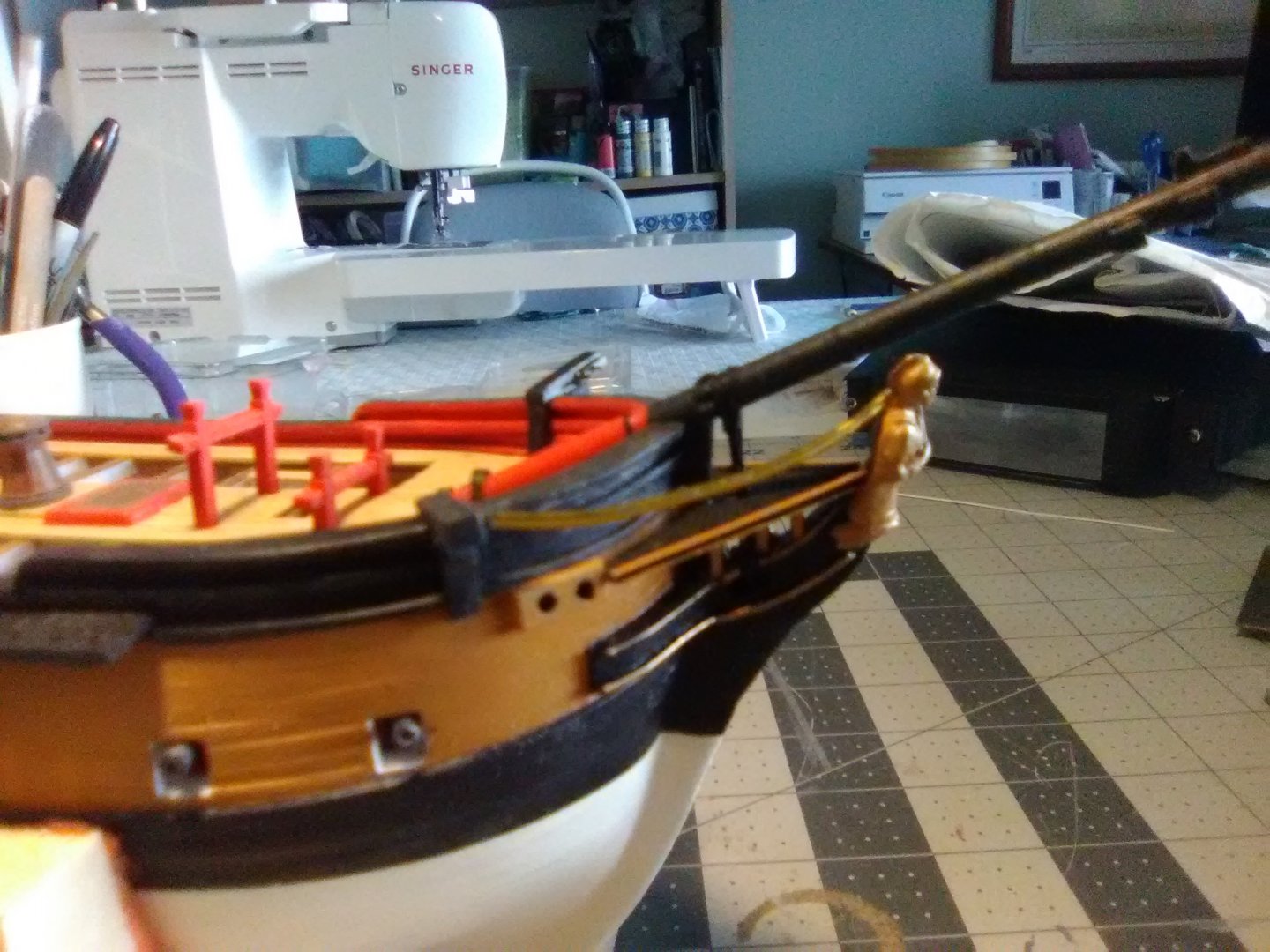
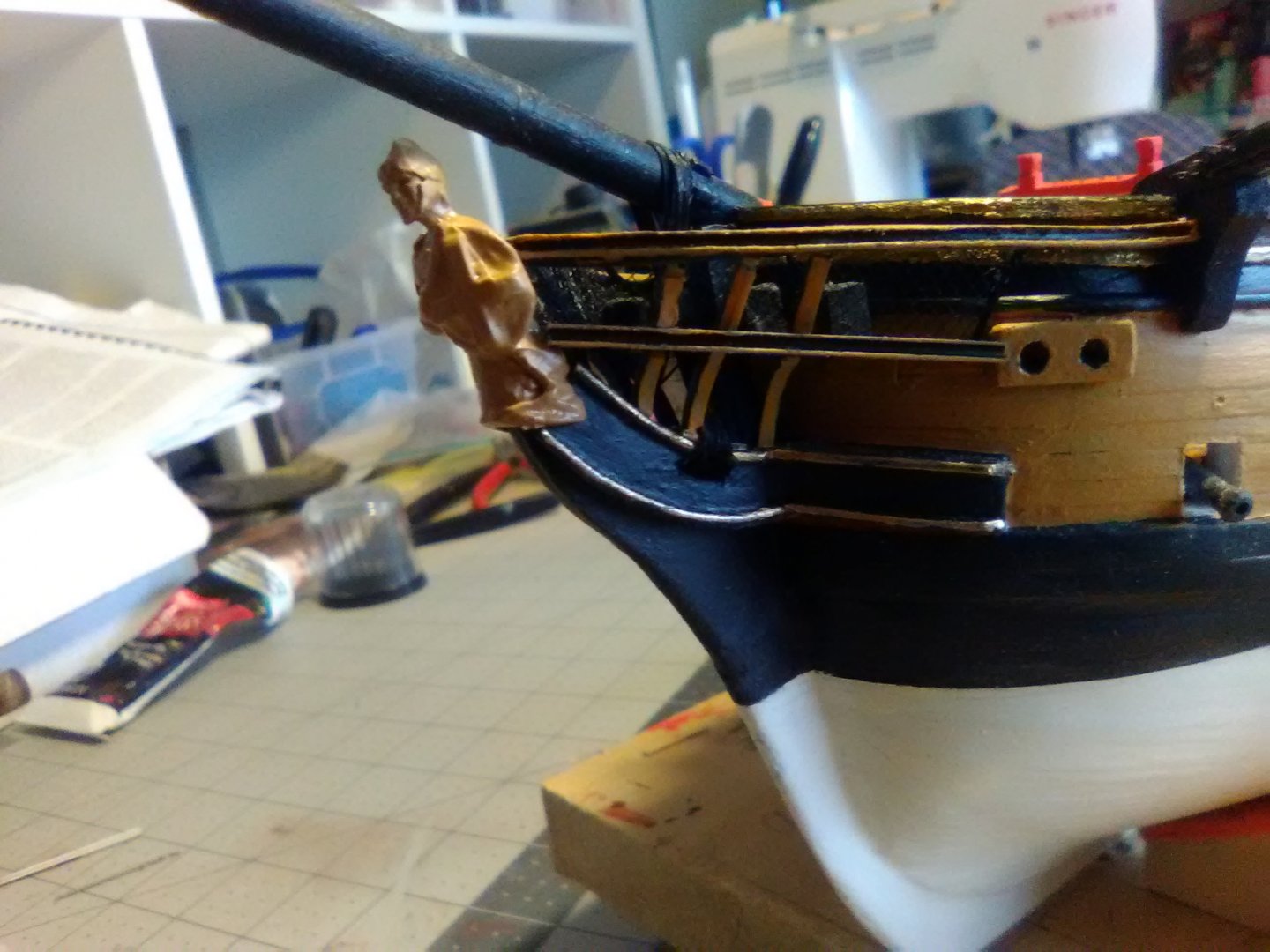
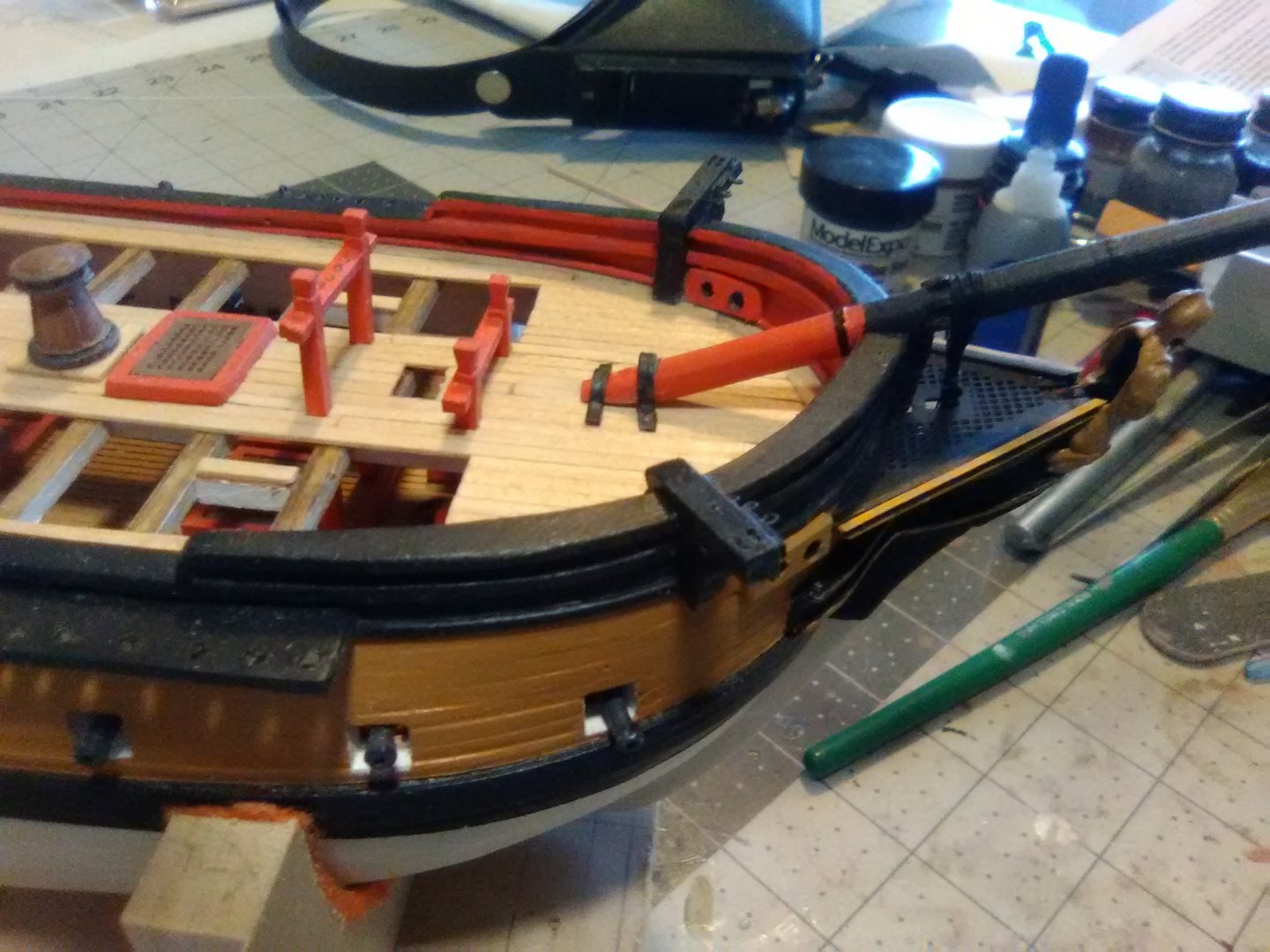
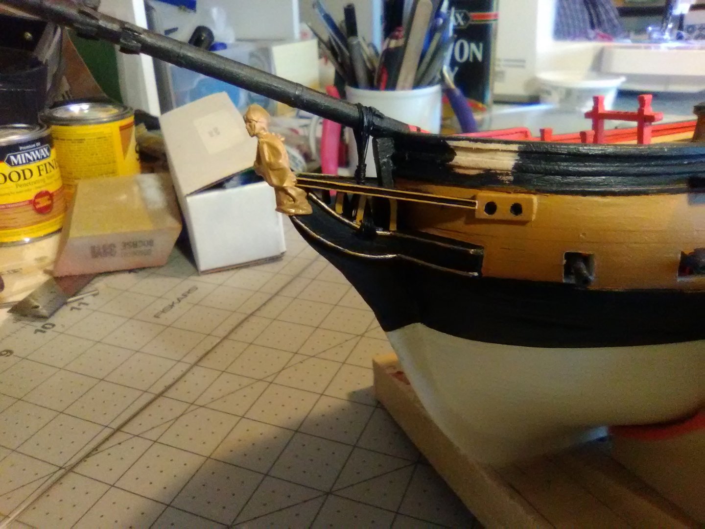
Bow Rails half done
The kit provides some 1/16” x 1/16” britannia strip metal for the bow rails. It is nice stuff to work with in this type of application. It cuts and sands easily and you can easily bend it into almost any shape with no spring back. The only thing you have to watch out for is that it will not stand up to multiple bendings - if I know it will take me several tries to get the right shape I use a piece of brass rod or wire as a template and then bend the britannia to match it.
I was playing around with the britannia when it occurred to me that it would work well to make the small timbers that run from the stem to the underside of the bow grating. The timbers are supposed to be concave and making them from wood involves a lot of trial and error but the britannia is exactly the width call for in the plans and it was an easy job to fit all 6:
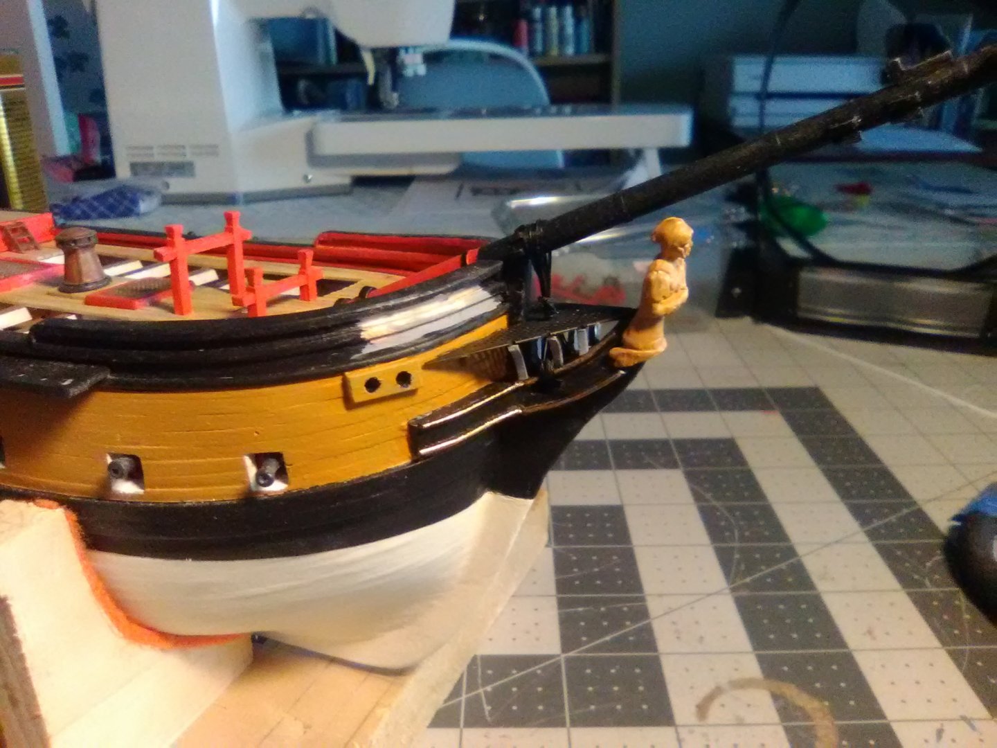

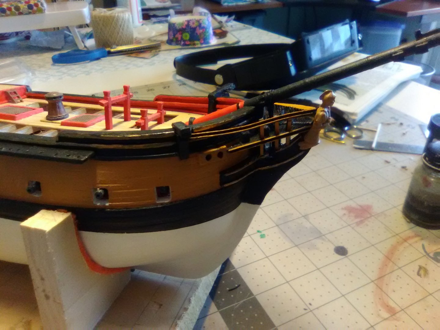
The next step was to place the lower rails along the outboard sides of the grating, pretty simple since there are no bends. The only problem is on all the period models I’ve seen they usually have some sort of decorative moulding on their outboard face which would be pretty hard to do with only 1/16” to work with. I was going to try it with some thin plastic rod like I used on the cheeks but I found some thin u-shaped channel material (Evergreen Scale Model .060" channel, item # 261) in my plastic stash that fits the outboard edge perfectly. After trying several color combinations of buff, black and gold I settled on buff and black:
I can’t do the upper timbers and rails yet because the upper rail fits against the cathead knee so I will have to put the catheads in first. I also needed to order more britannia strip from BlueJacket since using them on the timbers did not leave enough for the second half.
- KurtH, whitejamest, mort stoll and 2 others
-
5
-
Hi Thunder, thanks for the kind words.
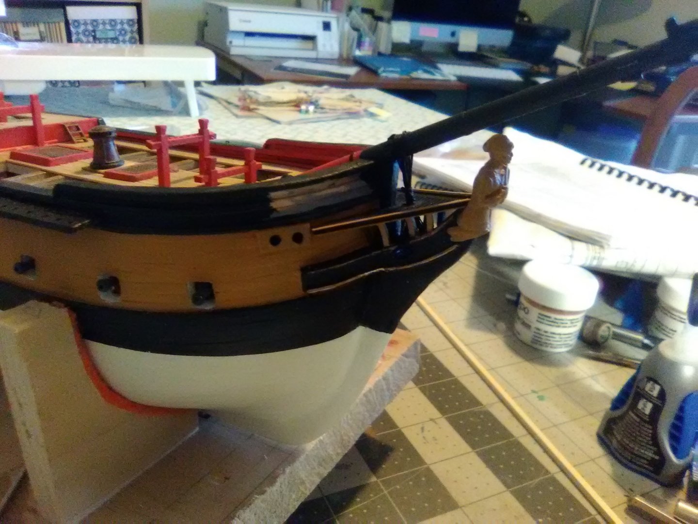
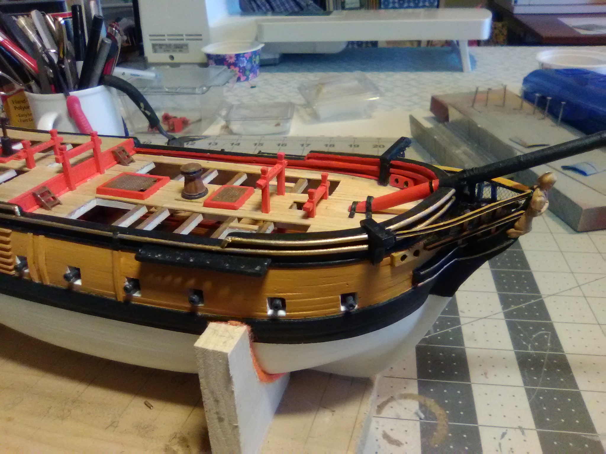
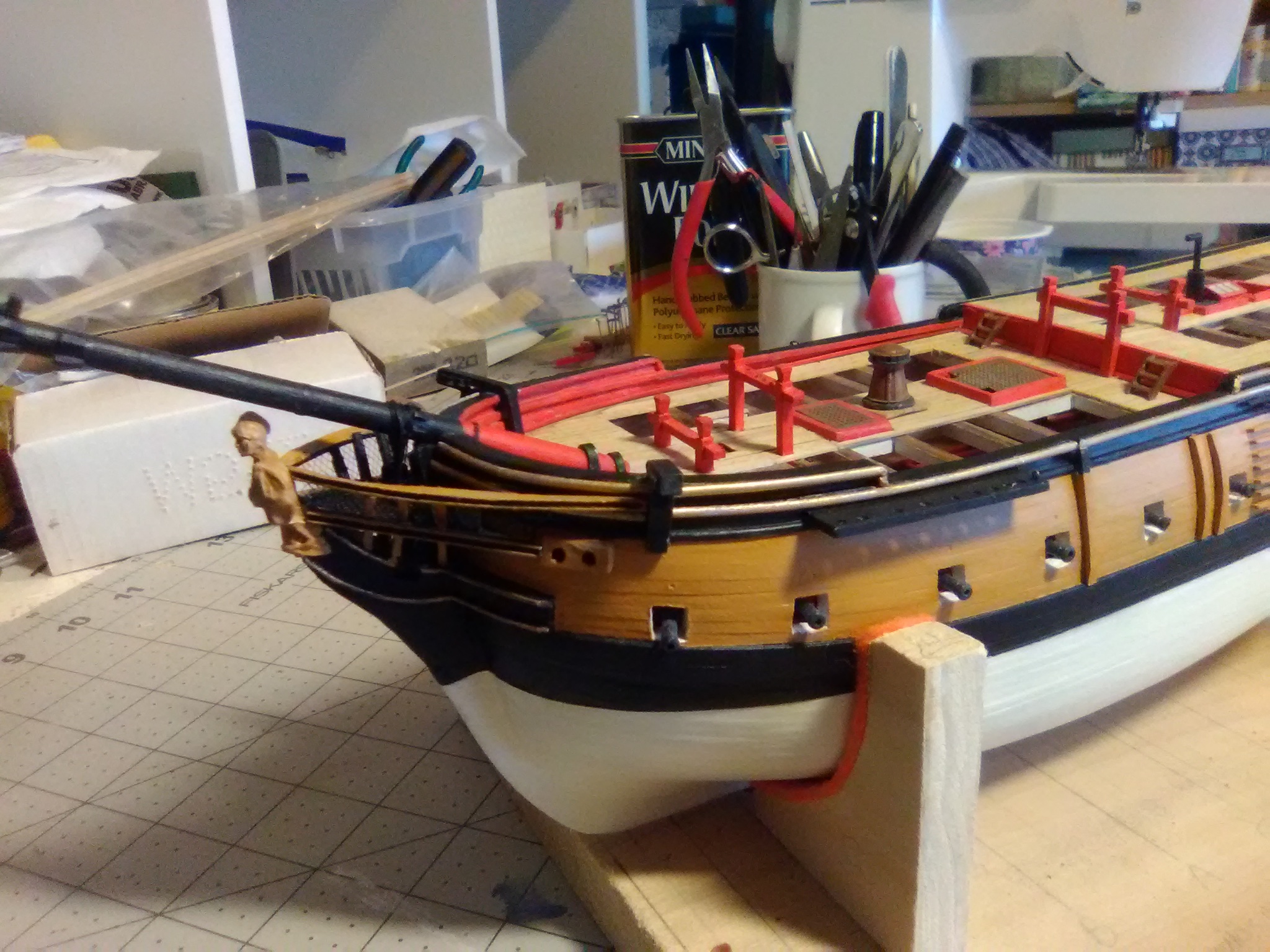
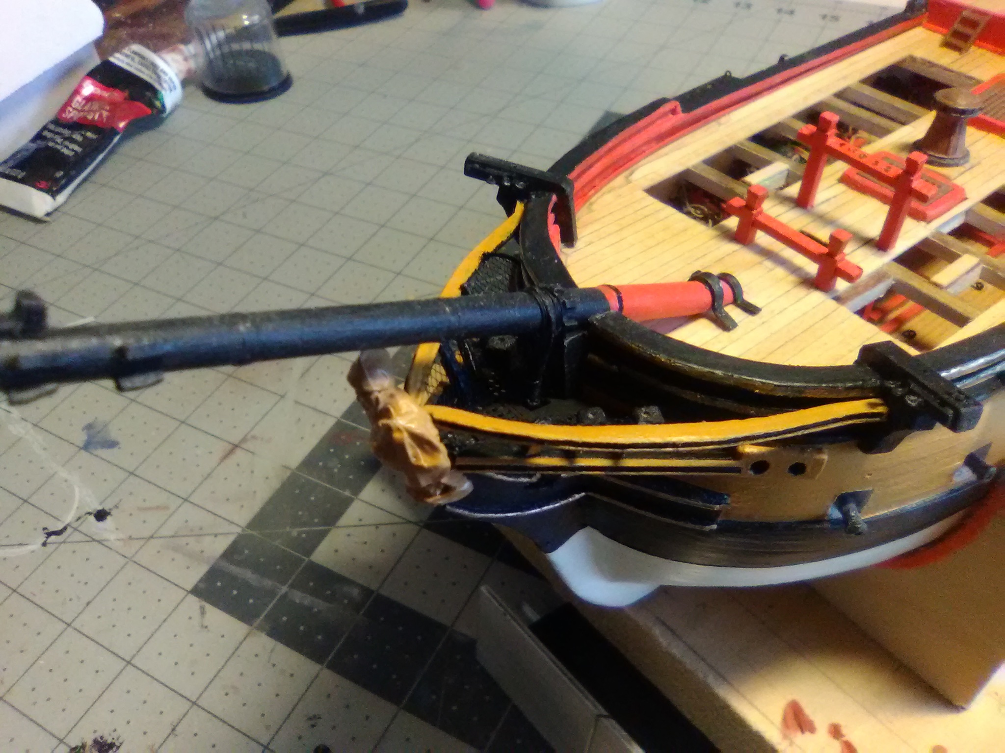
I had the same thoughts about the hawse locations, like you I'm used to seeing them closer to the stem and maybe on the deck below. My guess as to why this is setup this way was that ALFRED was built as a merchant ship and converted to a light frigate in a relatively short time. One of the big differences between her and purpose-built warships was that, although the ALFRED had a capstan, it did not go down to the gun deck and was apparently used just to haul the anchor hawser up from the cable tier. To actually raise the anchor a windlass was used (it will be fitted after the mast rigging is done) probably because merchant ships did not have the manpower to operate multi-deck capstans and it must have been a very slooooow way to raise the anchor. When the windlass is fitted it's heads are directly in line aft of the hawse holes, well out board of the the bits so I'm guessing they must have used some type of line stoppers to take the strain while the ship was at anchor. Definitely not the effecient set up on the ships you have modeled.


ALFRED by schooner - BlueJacket Shipcrafters - scale 1/8" (1:96) - Continental Navy Frigate
in - Kit build logs for subjects built from 1751 - 1800
Posted
I just used some black rigging thread from my stash (Amati maybe?) with a standard whipping rig.