


cookster
-
Posts
416 -
Joined
-
Last visited
Content Type
Profiles
Forums
Gallery
Events
Posts posted by cookster
-
-
Bob, what else can I say that hasn't already been said? Amazing work. I assume, and you probably stated earlier somwhere, are you using the AOTS book for your reference on masting and rigging? I should go back and re-read so pardon my laziness.... I ask because one day I hope I'll be rigging my essex....
-
Hi George. You can't go wrong with using hardwood. Jeff is great and you'll love anything you get from him.
Planking the hull in boxwood will be very nice. I've had to really work with the basswood planking on mine to get it where I can live with it, box would've been so much easier!
Thanks also for the comments about my parents. It's only been 8 months, and the holidays are coming so some difficult times are ahead. That's one great thing about this hobby, or any hobby for that matter- it takes my mind of those things...
Good luck with your build!
-
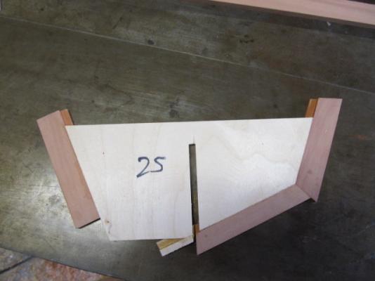
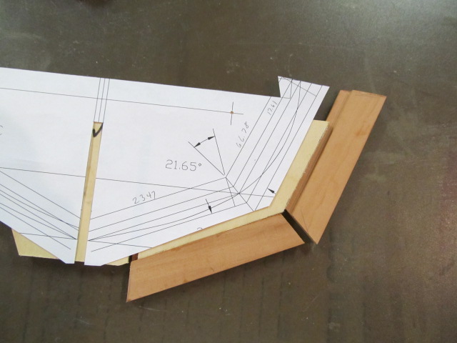
Next, another pattern was used for the "even" futtocks and floor timber.
The floor timber section was cutout of the pattern, then pear was cut to match and glued on.

After that dried the 2nd futtock was cutout and glued on. This 2nd futtock is the most dificult piece to cut as it has to be cut to the exact length and both angles, and glued in placed perfectly, for the futtock heads to flow smoothly. If I make any errors along the way I fear one (or more) of these is where I'll screw up - so I'm trying to be really careful.
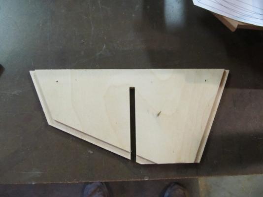
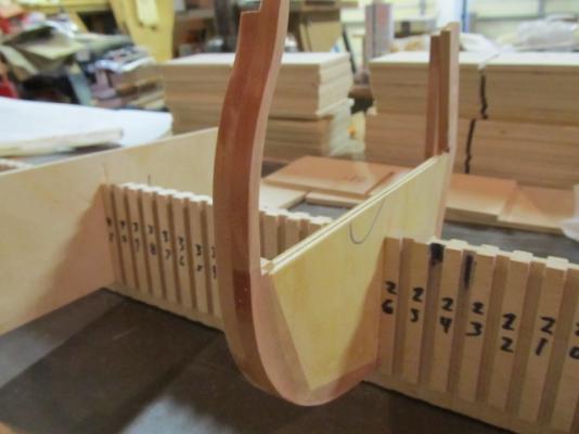
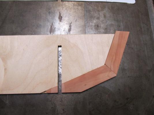
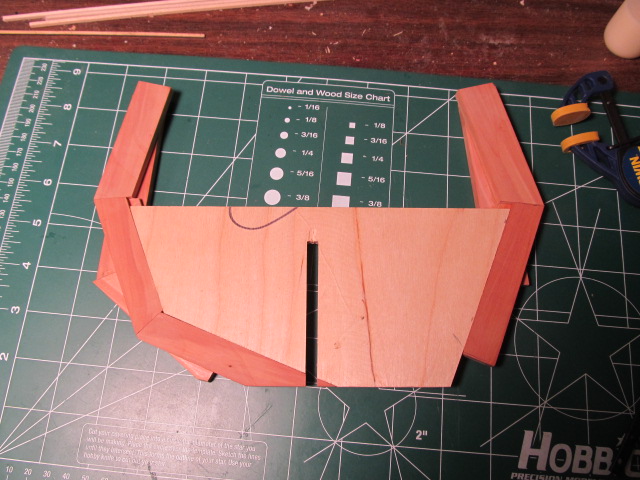
And here is current progress. The dado has to be cut back out and the bulkhead bottom trimed up. I'm working on getting quite a few frames to this point so I can cut them all at once.

I hope all this has been easy enough to follow. Hopefully when I get some frames finished and can show what this is all leading to it will make sense.
-
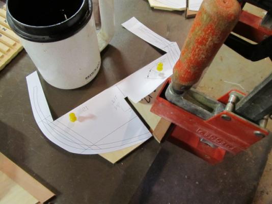
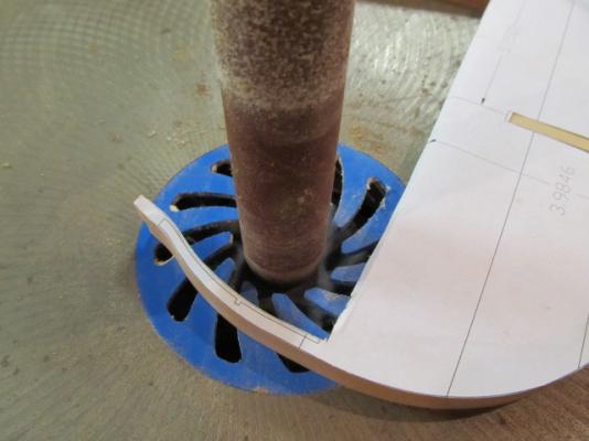
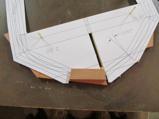
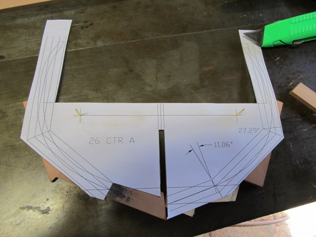
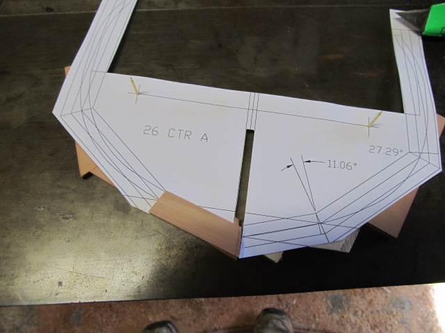
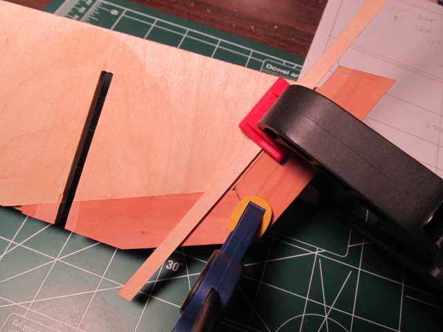
Next, another pattern was cutout to start adding the pear. These pear strips were rabbeted to fit in the rabbets of the ply bulkhead.
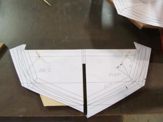
I first cut the angle to match the pattern.
The other end was marked for length, cut long and glued.
The next piece was cut to match the angle of the first, then glued on. It was also left long although it's difficult to see that here.

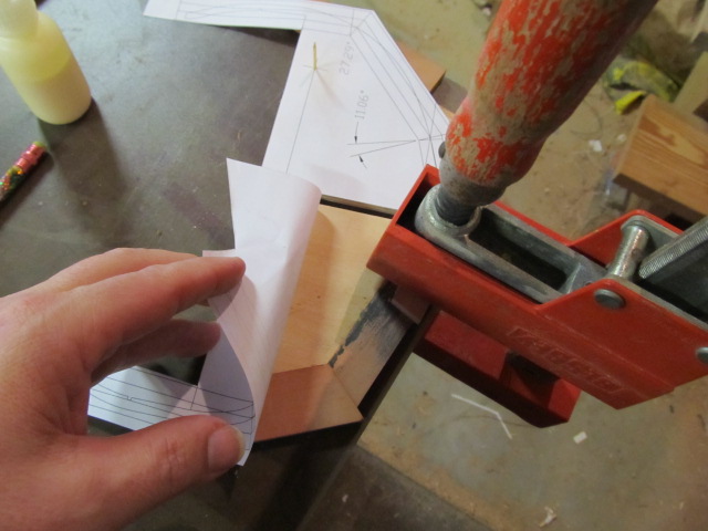
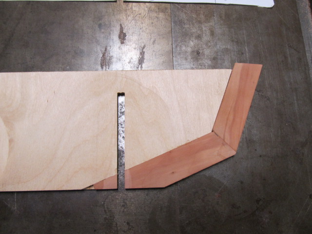
Next the pear for the other side was cut out per the pattern and glued on. This side of the frame will be planked, but to give myself some freedom later I went ahead and added pear here in case I want to leave off some planking, plus it makes it easier to add pear top timbers.

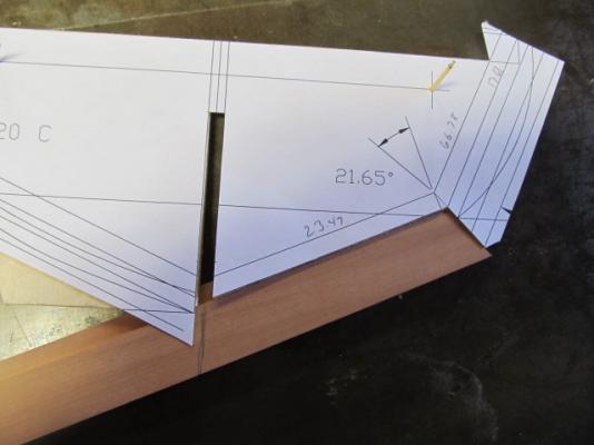
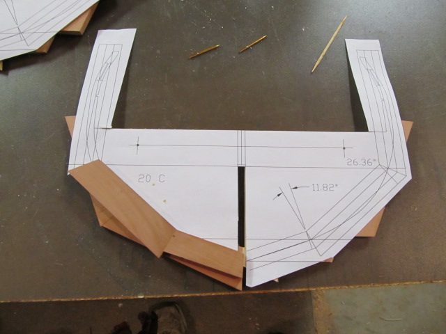
After all these pieces - floor timber and futtocks, were glued.
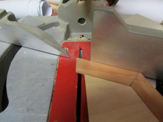
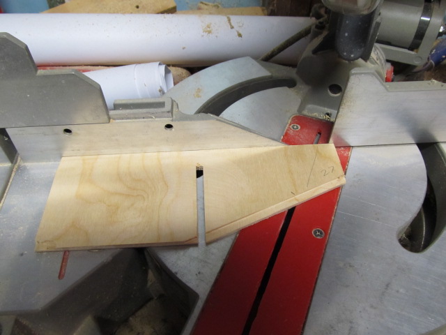
I cut the futtock heads per the pattern on the miter saw. I made a reference in one of my earlier posts about cutting this angle 90 degrees to frame, that was wrong! It is instead cut to a specific angle.
And here is the floor timber and 1st futtocks cut to length and ready to add the adjacent futtocks.
- mtaylor, GrandpaPhil, fatih79 and 3 others
-
 6
6
-
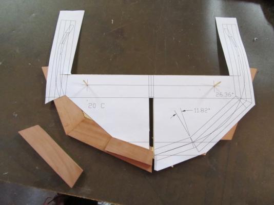
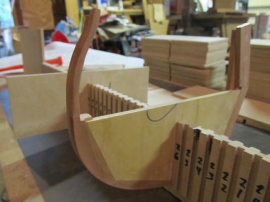
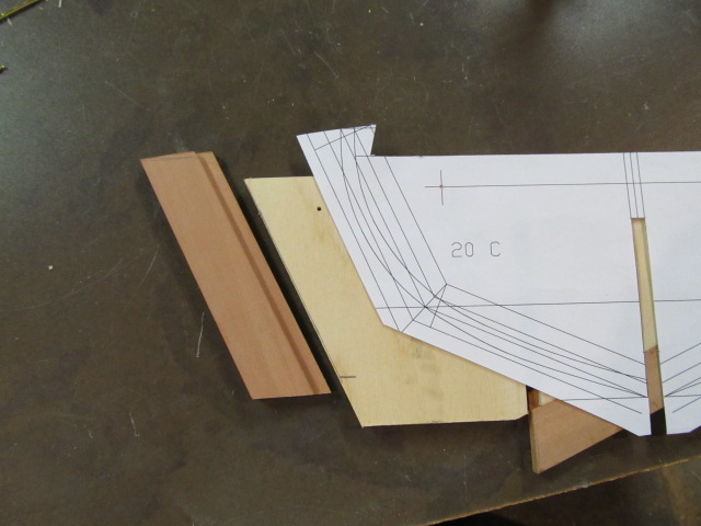
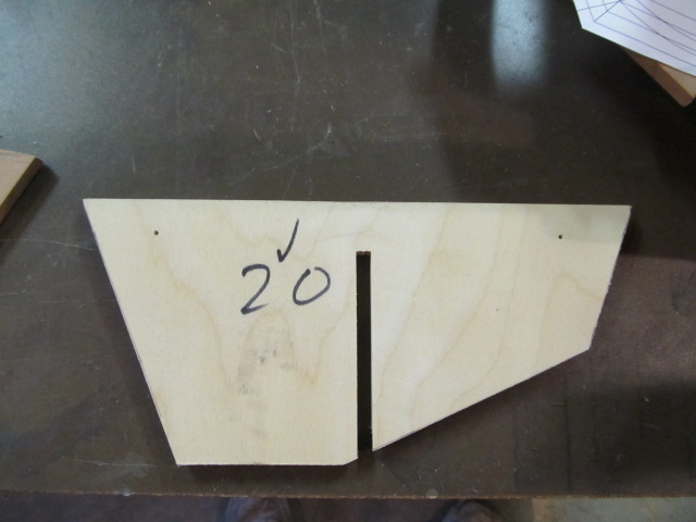
I mentioned earlier I lost some pics I had, so I will show one frame from start to finish. This frame is currently not completeted, so I will show it up to current progress.
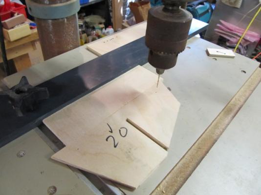
It's my frame "20", this is my numbering scheme - not Hacket's. It's easier for me to design using my own numbering.
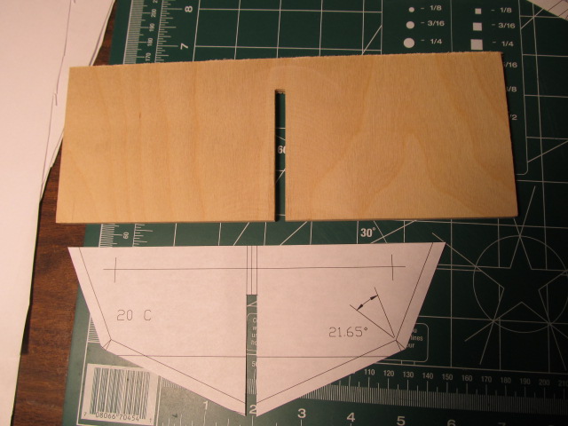
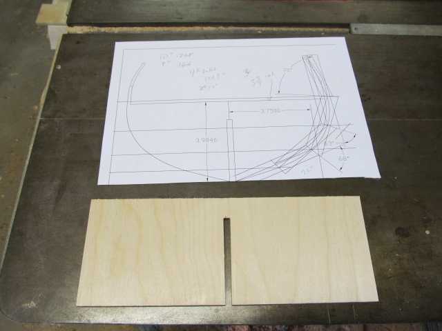
Here is the pattern. This is the floor timber and 1st and 3rd Futtock. Or maybe it's 1st and 3rd Futtock and top timber. One day I'll figure this out for sure.

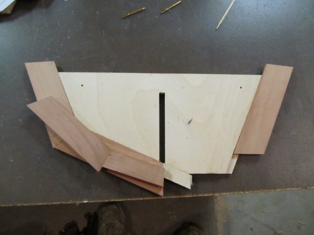
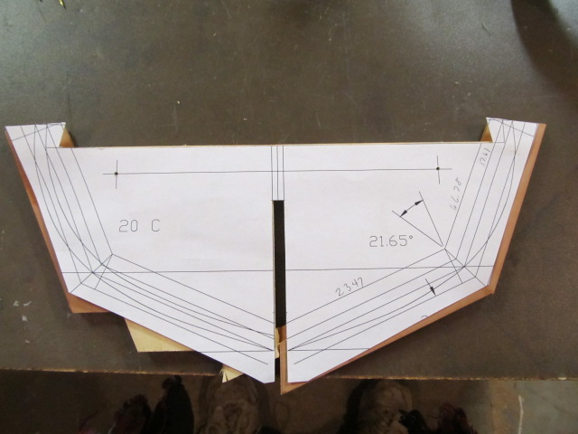
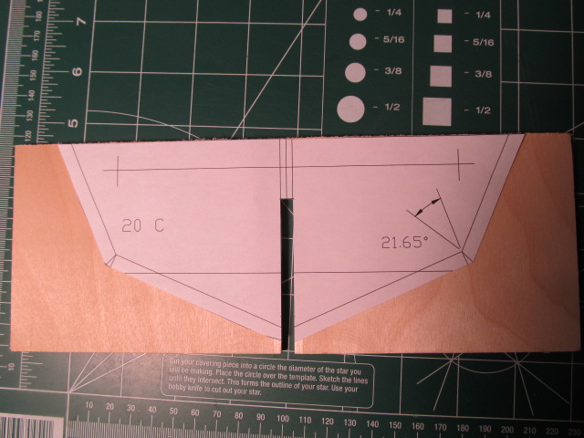
I cut the pattern so the ply blank can be marked and cutout.


The blank was cutout on the miter saw.

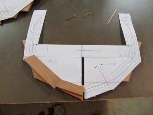
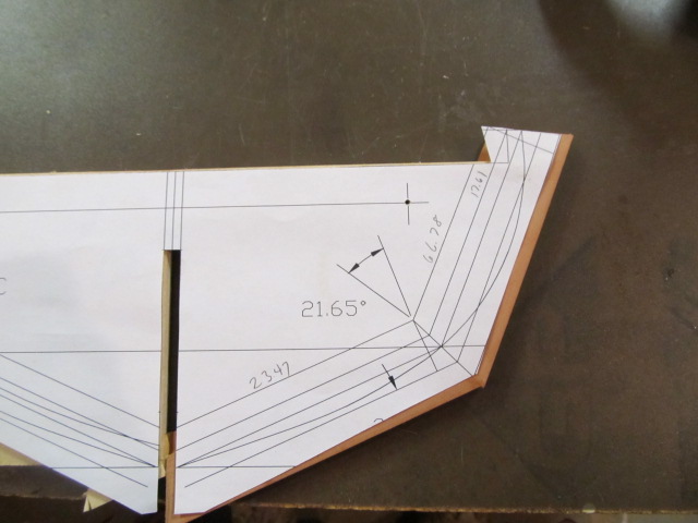
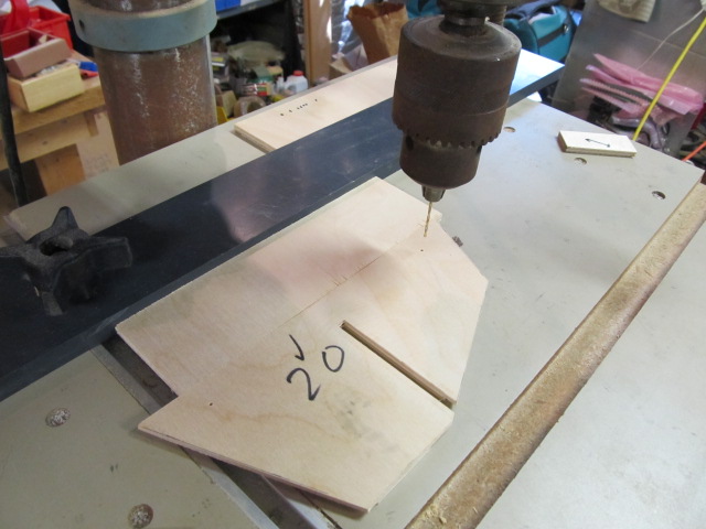
I cut the rabbets for the pear pieces on the router table.
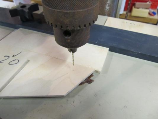
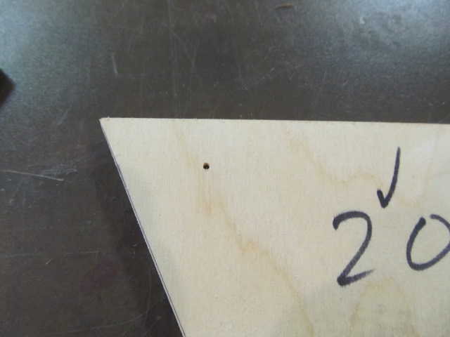
I then drilled the holes for the alignment pins. Here I'm not using a jig but after several frames were made I did make a jig. I will show that later when I describe the alignment pins. I also took this pic after I removed the paper pattern - I forgot to take it with the pattern still attached.


- GrandpaPhil, fatih79, mobbsie and 2 others
-
5
-
-
-
I had some pictures of my bulkheads in the early stages but I lost them. I'll take more as I make additional bulkheads.
So instead, here's pics of current process. Oh, and I'm still drawing... Sigh....
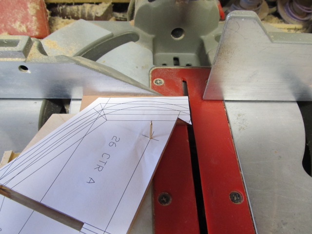
Here's a typical bulkhead in process.
These futtock section tops can be cut on the miter saw. (NOT 90 degrees to the frame as I earlier said!)

After cutting both third futtocks tops. These futtock heads are CUT WRONG! I cut them 90 degress to the frame which is not right. I caught this error after I made a few frames and had to start over on those.

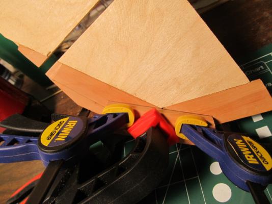
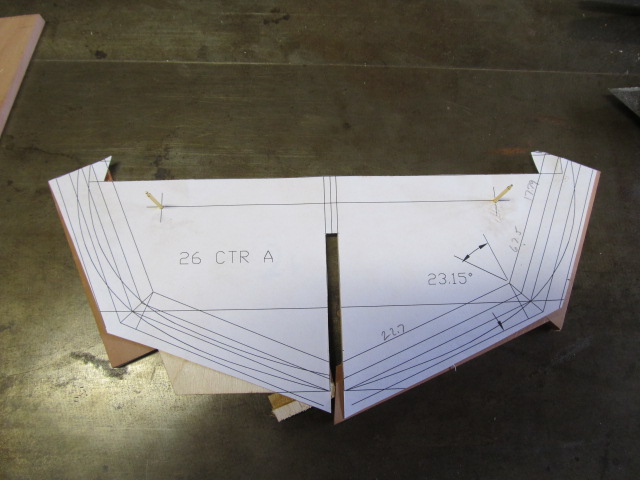
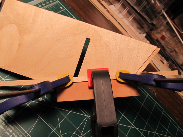
Here are various sections being glued. I use these Bessy clamps that I use building furniture. They clamp parallel to the jaws unlike some other clamps that can shift side to side.
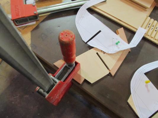

Now working on the afjacent floor timber. I made another pattern for the "even" futtocks. I started with the floor timber, the pattern was cutout where the floor timber goes.

The piece is cut and glued.


You can probably see in some of these pics I started using the brass alignment pin method to align the patterns. This is a tip I picked up from Ed Tosti. I'll elaborate on this more later.
- GrandpaPhil, augie, mtaylor and 3 others
-
6
-
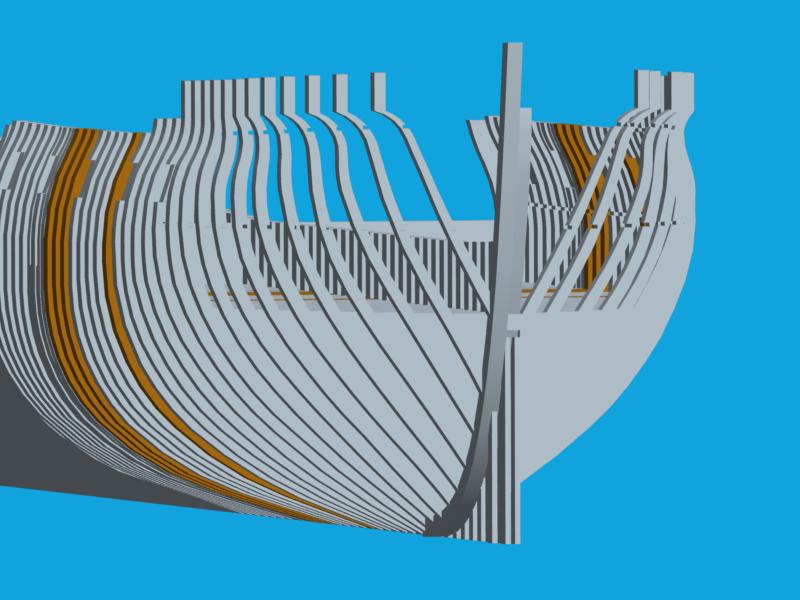
Hi folks, I posted a question on the Essex's bow shape here:
http://modelshipworld.com/index.php/topic/8272-usf-essex-bow-shape-1814/
I'm puzzled by the drawings of the bow shape shown on William Bakers drawings. I'm hoping some of the experts here can offer some knowledge.
In the mean time, here's a couple 3d renders of the proposed bow area as I think Baker drew it. The more I look at it I don't think it's right.


- fatih79, Wishmaster, WackoWolf and 1 other
-
4
-
Ed, I'm quietly following along. I can think of no new words that haven't already been used so I'll simply say your build is amazing. I'm learning so much watching you and your methods. Thanks so much for posting in all your build logs so we can all learn from you!
- CaptainSteve, WackoWolf and Jack12477
-
3
-
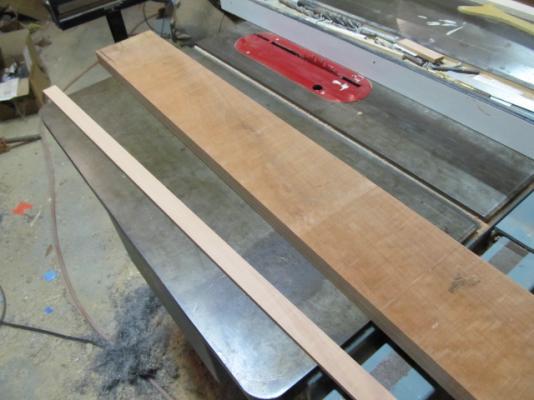
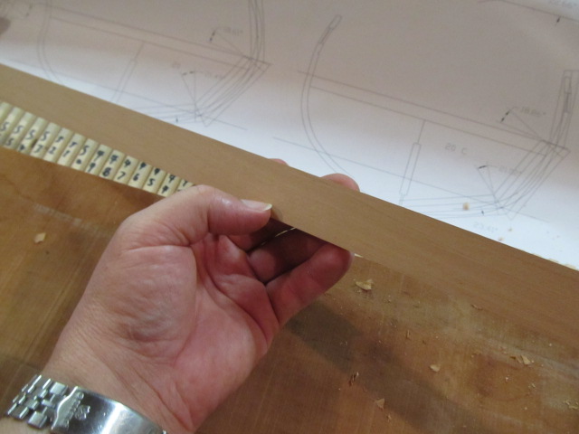
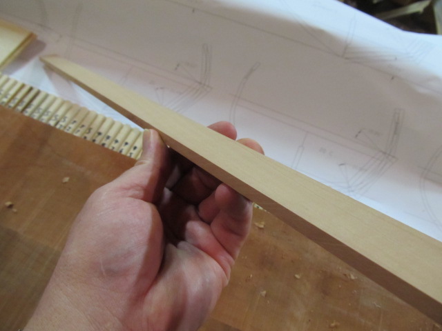
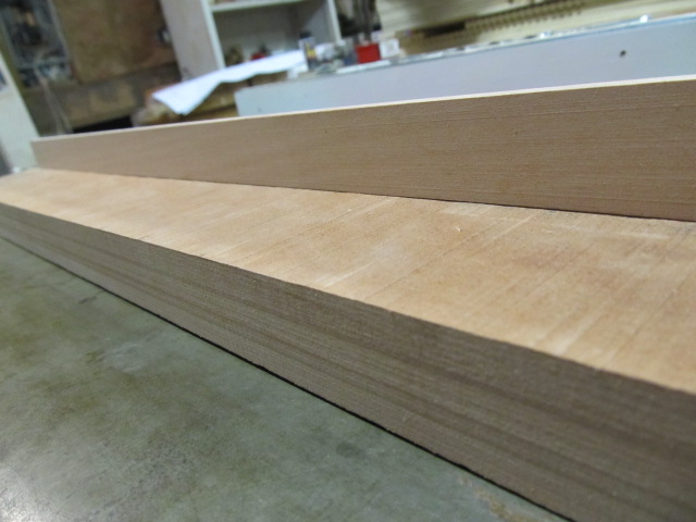
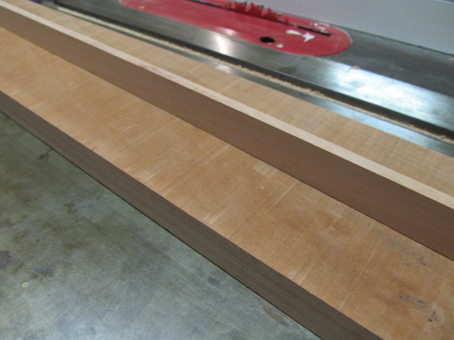
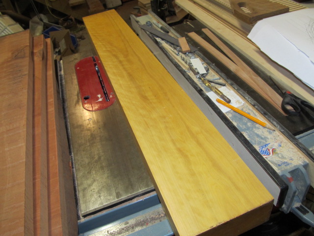
I got a strip ripped and milled from the pear blank i bought to see how it looks, very nice stuff. I'm pleased. Now on to milling many strips...


- GrandpaPhil, mtaylor, augie and 5 others
-
8
-
Tim, on the glue I use Elmers carpenters glue for all my interior projects. I've also used titebond on some things since it's water proof, but it dries a little yellow. Elmers dries clear. Just a personal preference.
The elmers glue sticks I mentioned are for gluing the paper patterns on. It works great for that.
-
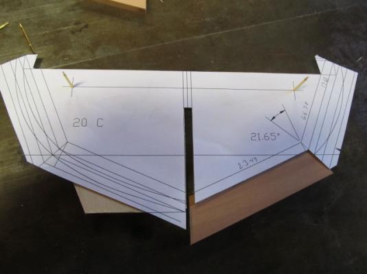
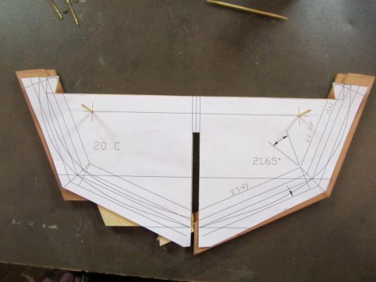
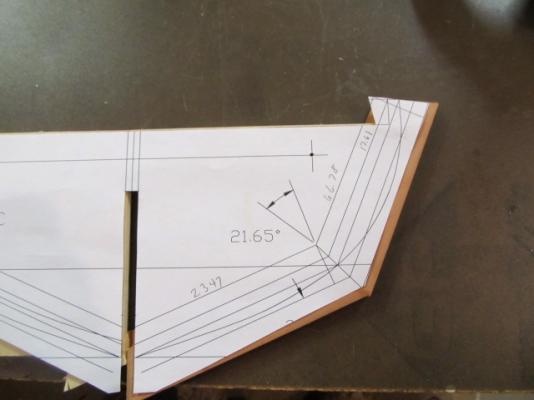
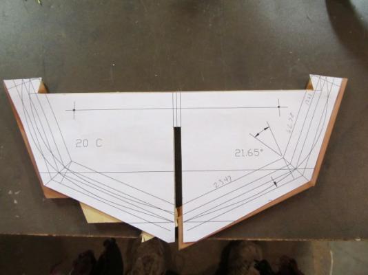
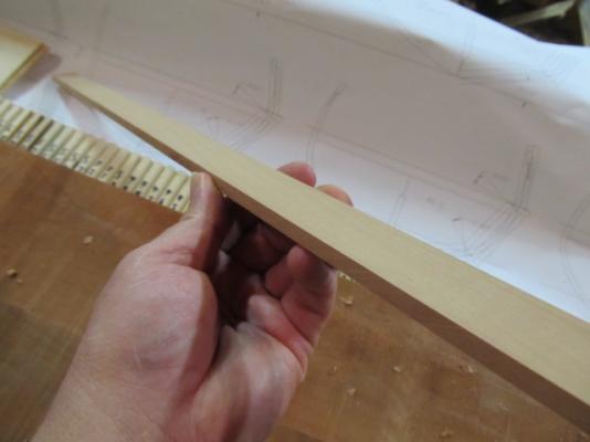
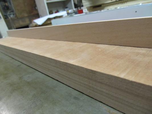
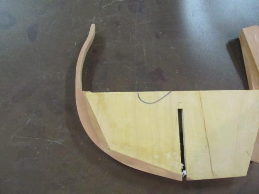
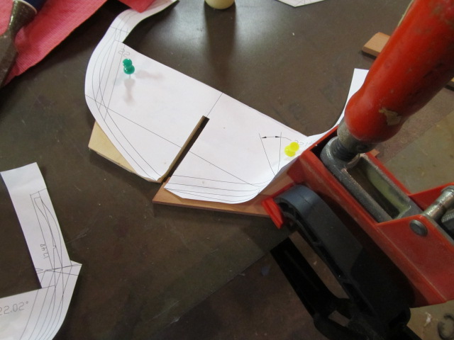
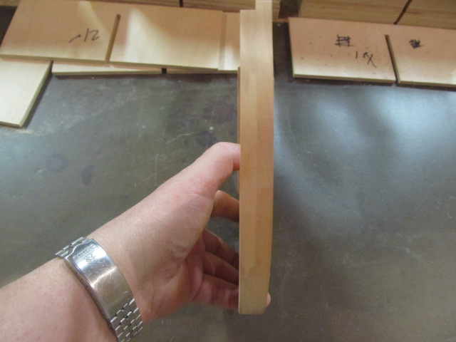
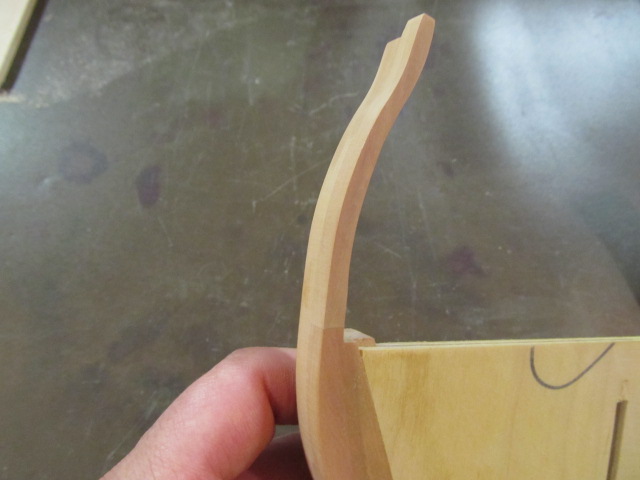
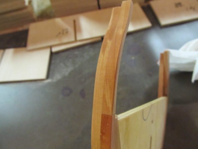
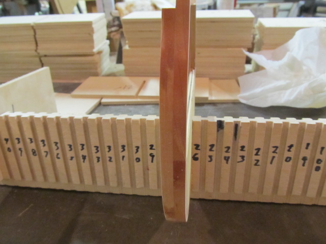
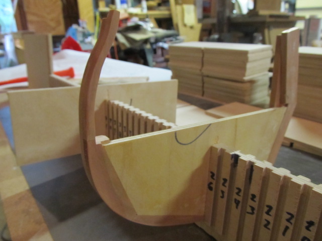
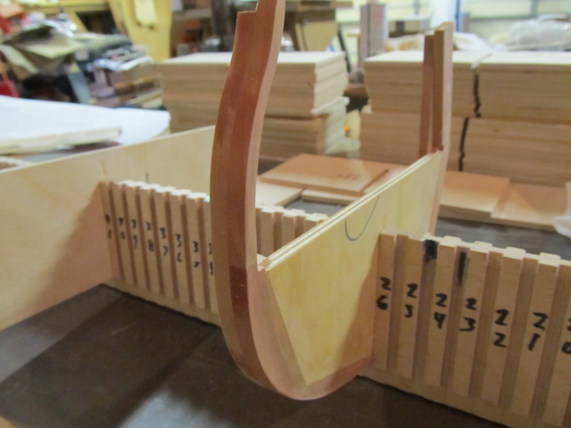
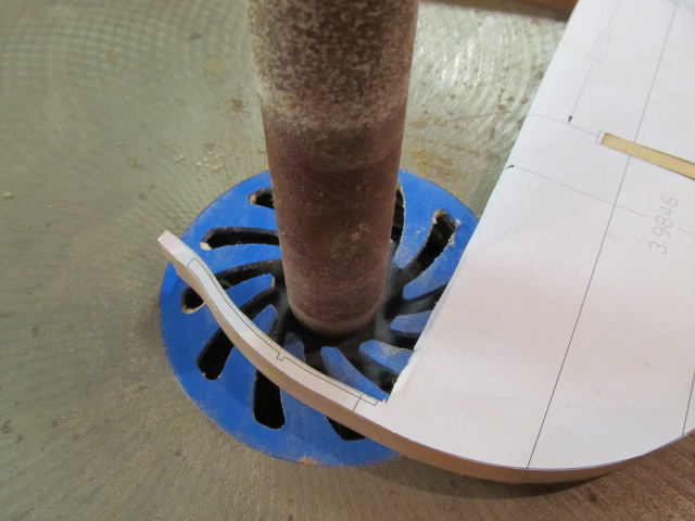
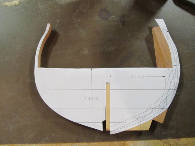
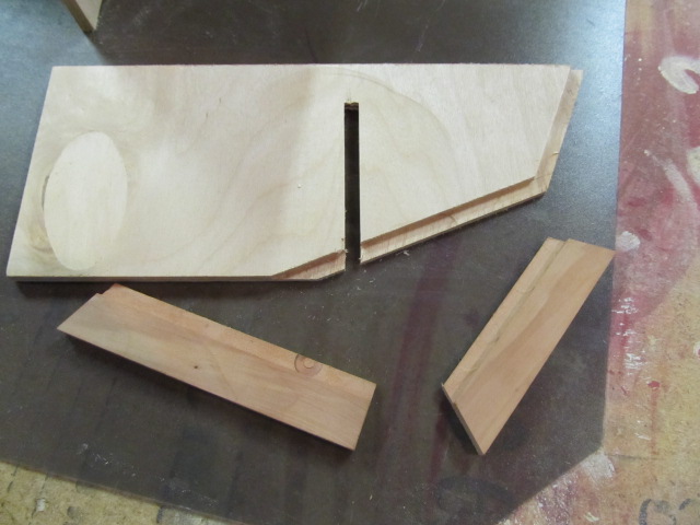
A few pics of the frame half.
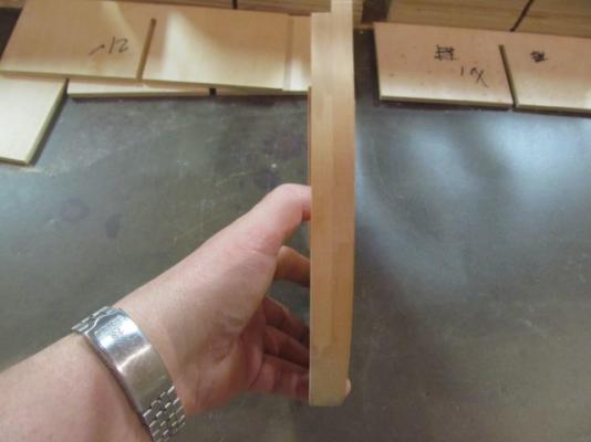

I wet the frame to show the joints.
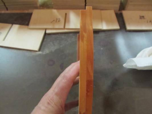

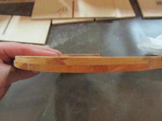
Also, the grain in the pear I used is not very good, it's from another piece of pear I had, not the blank I bought. I expect that pear to look much better.
And sitting in the bulkhead. Now time to do this for real...

-
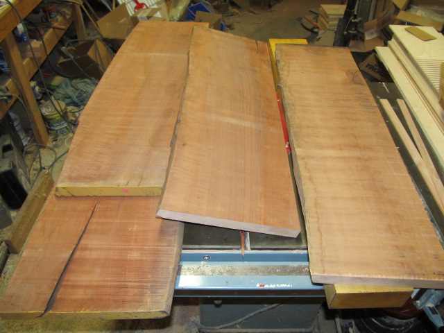
Tim, as far as board ft, I made some guess calculations but it actually came down to what size boards I could find. The pear blank I bought was
12" wide2 feet wide by 6 feet long. If my guesses are right that's enough to frame my essex twice, but that's figuring no waste, so I do think I have enough. The boxwwod blank I bought should be more than plenty for planking, etc.Oops, I got my width wrong - the board was 24" wide before they ripped it to 12" for shipping.
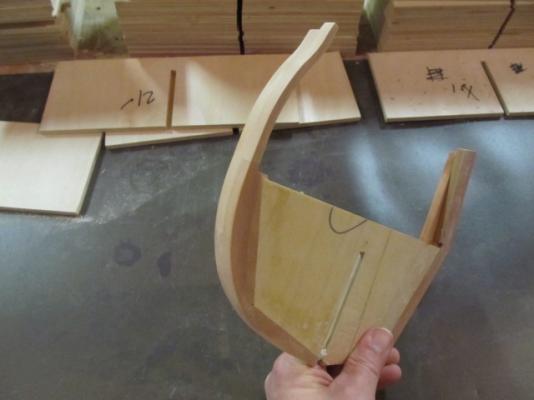
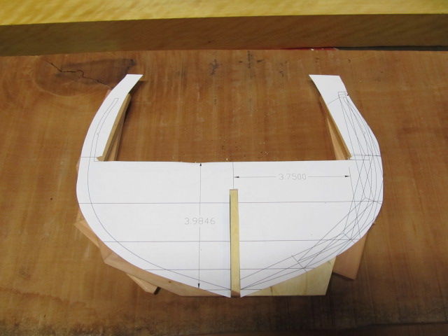
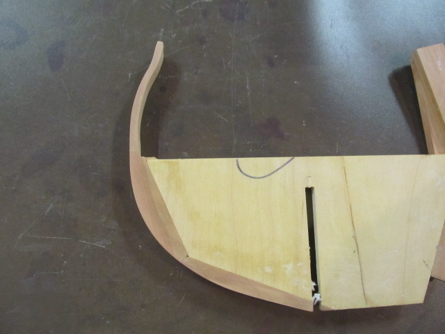
I got my test frame made. I was going to cut both sides but just decided I didn't need to for this test. Also I printed my pattern undersize by accident, so I had to shift it making the other side off anyway. Yes I could've printed another one, but it just wasn't necessary at point I discovered this.
First the pattern was glued to the frame. I used elmers glue sticks which I saw in Ed T's log thinking that glue wasn't strong enough, but if Ed used it, it must work. Confirmed! The glue stick works great.

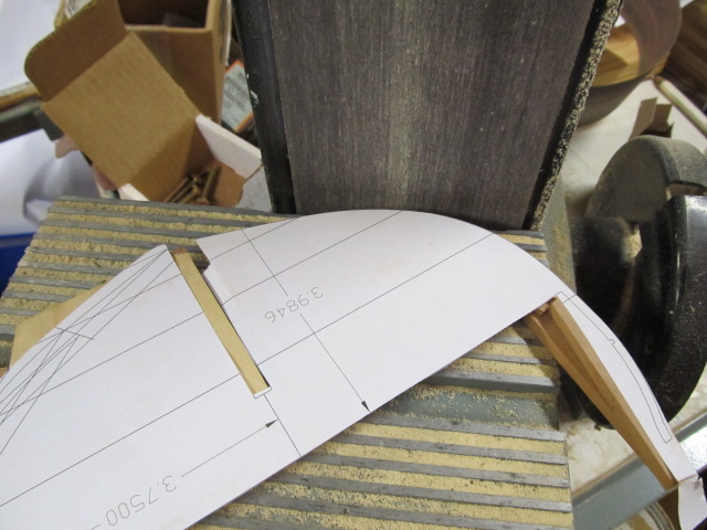
The pattern was cut out with a scroll saw. Then I sanded the convex convex curve with a belt sander.

Then I sanded the concave areas with a spindle sander.
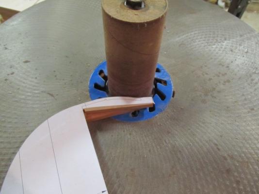
Done.

You can see an area at the top of the bulkhead flat area that isn't sanded smooth, but that doesn't matter since that will be under the gundeck and won't show.
-
-
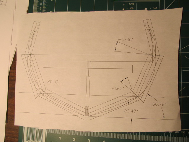
I tought I'd expain some of my framing ideas for Essex since I plan to start cuting actual frames very soon. I've done a lot of reading in the last year on frigate construction trying to gain the knowledge I need. I've also had some good help from several members here. Most of the POF models Ive seen show the futtock frame members stepping down as they rise, preseumably to save weight and use less timber - according to Goodwin. Also, to lessen rot as the airspace between timbers helps them dry out.
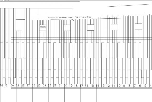
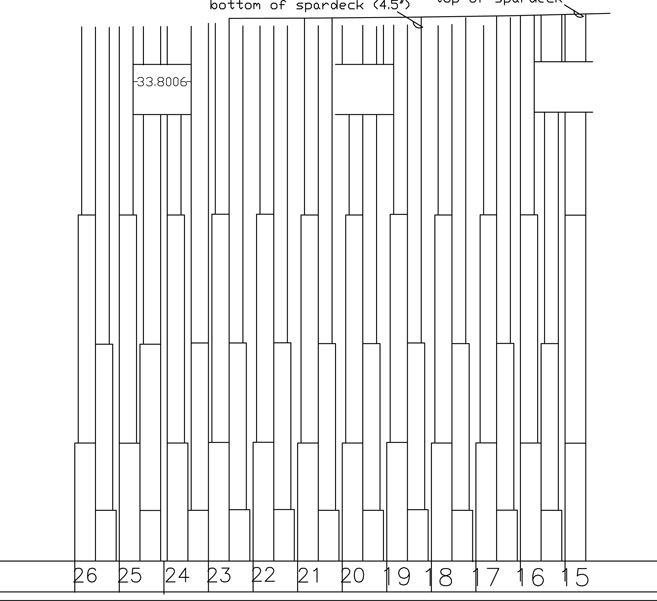
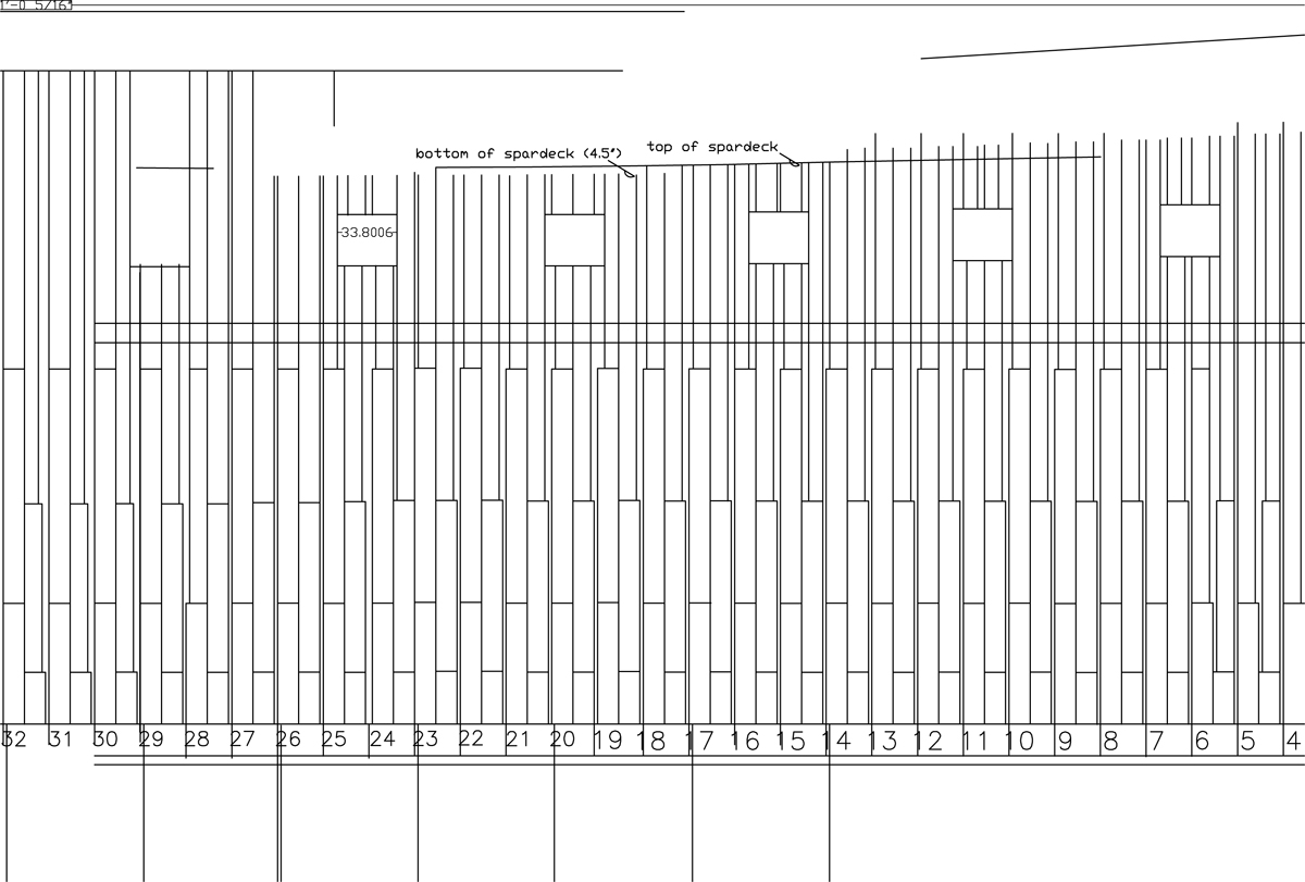
Portia T's framing plan of Essex shows this stepped construction as well, so I finally decided to use that method. My plan was to use width's of 12", 10" and 8" as the futtock widths. I made a set of drawings based almost exacly on Portia's plan, a section is shown below.

Note, the frame numbers are my numbers, not the numbers from the Hackett or Baker draughts.
I liked the idea of the stepped frames as it seemed to give the model some elegance in its frame construction. But, I've been doing more reading, I found a few more people either building Essex or drawing her, and there were some varying opinions on how she as well as the other American frigates of her time were framed.
Some are of the opinon the frames were not stepped, but were the same width (siding?) all the way to the top timber. This basically gives the American Frigates a "wall of timber" appearance when the planking is removed. There's even a photograph of Constitution with her planking removed showing her framing just like that. We all know her name of "Old Ironsides", earned from the cannon balls bouncing off her hull due to her massive frame and plank thickness. Is there any reason to think she was the only American frigate built that way? Or were all the American Frigates of that time - including Essex, framed as such.
Fox reported in 1807 most of Essex's upper timbers were rotten, maybe this rot was accelerated due to no airpsace between timbers?
I still like the stepped timber look, but I think to be a little more (hopfully) historically accurate I'm only going to step the 3rd and 4th futtocks. The first and second will be the same width as the floor timber, in my model's case 12". Room and space on my drawing, based on Portia's drawing, is almost 28", so when using 12" timber I will still have spacing between each frame pair - which I like. I must admit the wall of timber look is not what I'd like for the frames on my model. Image below:
Also note I have not yet drawn the futtock heights varying with the shear, but I will before I start construction.
Not all the frames in that drawing have been moved, but most under the gunports should have been. Using this method I may need to tweak the location of some gunports due to some of the frames moving, not sure about that yet. I could also use frame spacers to take up any gaps, as I think that's what the RN ships did.
Neither of these methods may be 100% historically accurate, but I'm trying to get somewhat close and still have a model that is pleasing to the (my) eye.
Comments, concerns welcome. Frolick, this means you....
Thanks for looking in!
- mtaylor, hexnut, CaptainSteve and 1 other
-
4
-
No problem Tim. Yes, I ordered from Gilmer Wood Co, https://www.gilmerwood.com.
I looked at several online sites for exotic hardwoods and decided to go with them. There is a topic in the Wood forum area on "where to buy wood", Glimer is listed there - that's how I found them. At the time I was looking they were the only one I found that had pear and castello boxwood in the large boards I wanted.
As far as pricing, it gets a little muddy after a while looking and comparing prices. I finally decided to give Gilmer a call to confirm they had what I wanted, and the fellow was very nice and seemed to know his stuff. I told him I was buying for model ships. In the end I may have paid more from them compared to someone else, I honestly don't know, but when the boards arrive and if they are what I expect them to be then I'll be happy and not sweat over saving some $$ (or not).
Let me also add a word about buying milled lumber from Hobby Mill. I've bought from Jeff and the quality is outstanding, and I'll do it again if the need arises. You definitely get what you pay for. But on a project like my Essex, there's no way I could come up with a material list to buy from Jeff - cause I have no clue yet. It would be a complete guest-i-mate if I tried.
Buying larger boards and milling to the sizes I need is the way to go for this project, and it will save me money over buying milled wood - which on this monster will be save me a lot of $$. I already have the tools I need to do this so that makes the most sense for me.
Thanks for looking in!
-
Tim, I'm making the frames from Pear, and probably most of the deck furniture. I'm still not sure what wood I'll use for planking. The decks will be Castello Boxwood. There will probably be a few other species mixed in for specialty items.
I ordered my pear and boxwood boards and hope to have them by Friday, now if I can just finish this darn frame lofting.....
-
The next futtock section was glued on.

The angle on the second section was easier to cut, and more accurate, after it was glued on.
The second section was glued on.
The overlapping frame futtock was cut out and glued on. I guess this section would be the second futtock as the floor timber would mate to this, so the sections I already glued on would be the first and third futtock.
More to come.
-
I started making my test frame. I'm still working on my drawings so nothing to show yet.
As I mentioned earlier I'm building Essex partly POF but using plywood bulkheads for the lower half of each frame pair, so in essence a hybid approach.
Also, I am no expert in ship construction or lofting of plans so I will probably make mistakes in my representation of how I will build my Essex. It's the best I can achieve at my present level of knowledge. I will elaborate later as to how I developed my plan.
This test frame is a center frame in which the futtocks are not stepped but are full thickness all the way to the top timber. I assume this is accurate for Essex as Portia T. shows this on her framing plan. The plan I show below is a work in progress and is not detailed enough for anyone else to use but at least I understand it.

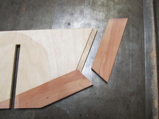
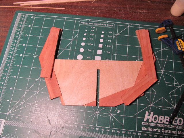
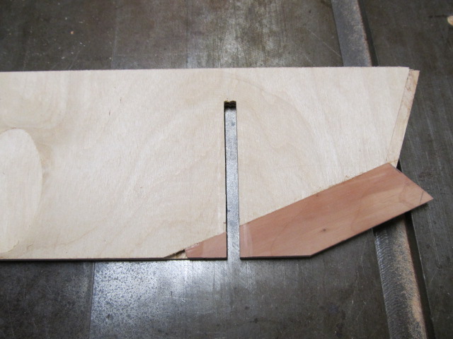
First the bulkhead blanks were cut down to the height I wanted. Then using a miter saw I cut off the angles on the sides of the bulkheads where the pear futtock material will be glued.

I cut rabbets in the pear and ply bulkhead that will be the glue joint. I cut these on a router table.

The first futtock section was glued on.

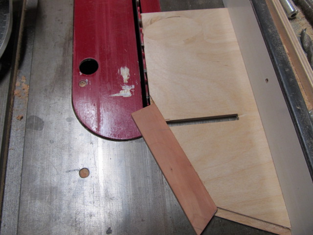
The piece I attached ran long over the end of the bulkhead so I ripped it down on the table saw.

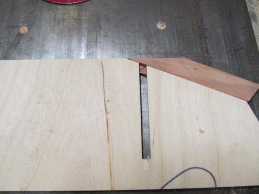
This piece also blocked the slot for the bulkhead so it was cut out.

-
Very nice Tom, shes looking good!
-
Yes I am. I'm actually drawing on it again right now. Hope to get in the shop this weekend a cut some test frames.
-
Tim, it's the Young America - Extreme Clipper by EdT. It is a great guide. And Ed's a master ship builder. Look at his Naiad build - fascinating. Look at anything he does for that matter!
http://modelshipworld.com/index.php/topic/3453-young-america-by-edt-extreme-clipper-1853/
David I haven't documented anything yet but I plan to, to what degree I don't know yet. If anybody wants to learn to loft plans, as I did/do, read EdTs log.
-
Hi Tim, sorry it took me so long to reply, I've been on a very long break from building. I've finally started work again and hope to post some more pics soon.
One of the issues I ran into when drawing my plans was my lack of knowledge on lofting ships plans, I just started the best way I knew which worked OK, but I did start to get frustated when I realized I was making too many errors from lack of knowledge. Then, I found Ed Tosti's log and posts oh how to loft plans (the right way) and it all clicked. I'm redrawing my frames again and am going back to correct subtle errors now, not huge ones. I'm really looking forward to making some more sawdust on Essex soon.
Thanks for looking in!


Bomb Vessel Granado 1742 by mobbsie - FINISHED - 1/48 - cross-section
in - Build logs for subjects built 1501 - 1750
Posted
Hi Tony, I missed that you finished your Aggy and started this one. Now that I've found your build I'll definately follow along. I wish you the best of luck!