

Bedford
-
Posts
1,190 -
Joined
-
Last visited
Content Type
Profiles
Forums
Gallery
Events
Posts posted by Bedford
-
-
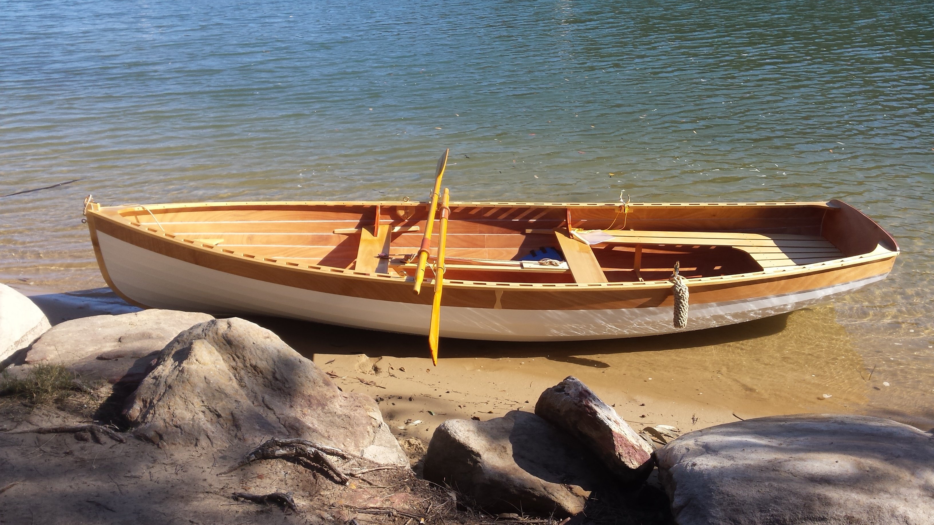
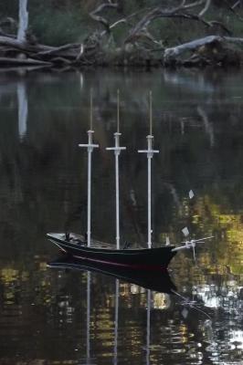
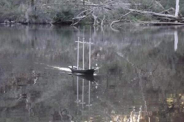
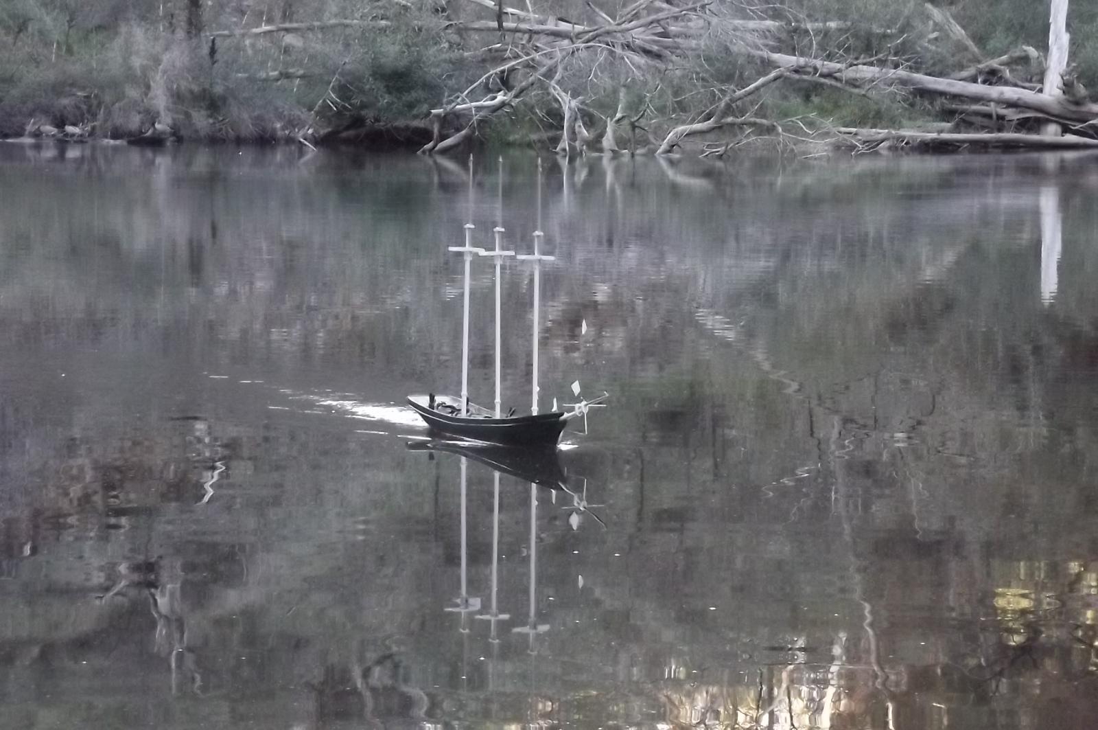
So, to part two of the sea trial storey.
Sorry the camera was not level but you get that in the bush with only rocks for tripods.
Generally this is at fairly low speed which is more than adequate but she has much more go than that which means she will be able to drive against the wind if I need to. At the end I was heading in and gave her full power but she didn't speed up properly and sounded odd. Keep an eye on it right to the end.
Pay attention to the upper left quadrant at 1:30, that is a platypus, not that you can really see it.
-
-
You and I are alike in that the joy is in the building. We have slightly different goals but our models may only sail a few times, just because they can.
I mentionned earlier that I may have something to show.............
Does it fit in the car?
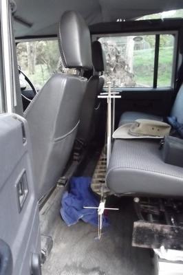
Easy, granted if she had shrouds on they would be fouling on the seat but I could make a simple centering cradle to prevent that.

There's more but I need to sort the details first.
-
It really is amazing what we can find lurking in the wood isn't it?
-
Thanks Michael and Bob, I relish the challenge this build provides me.
Michael, will your cutter be R/C?
Steve
-
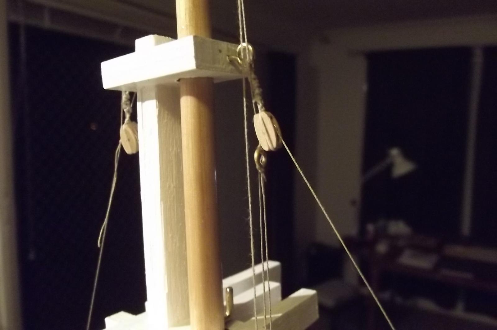
Hey Jerry, I've got another one for you!
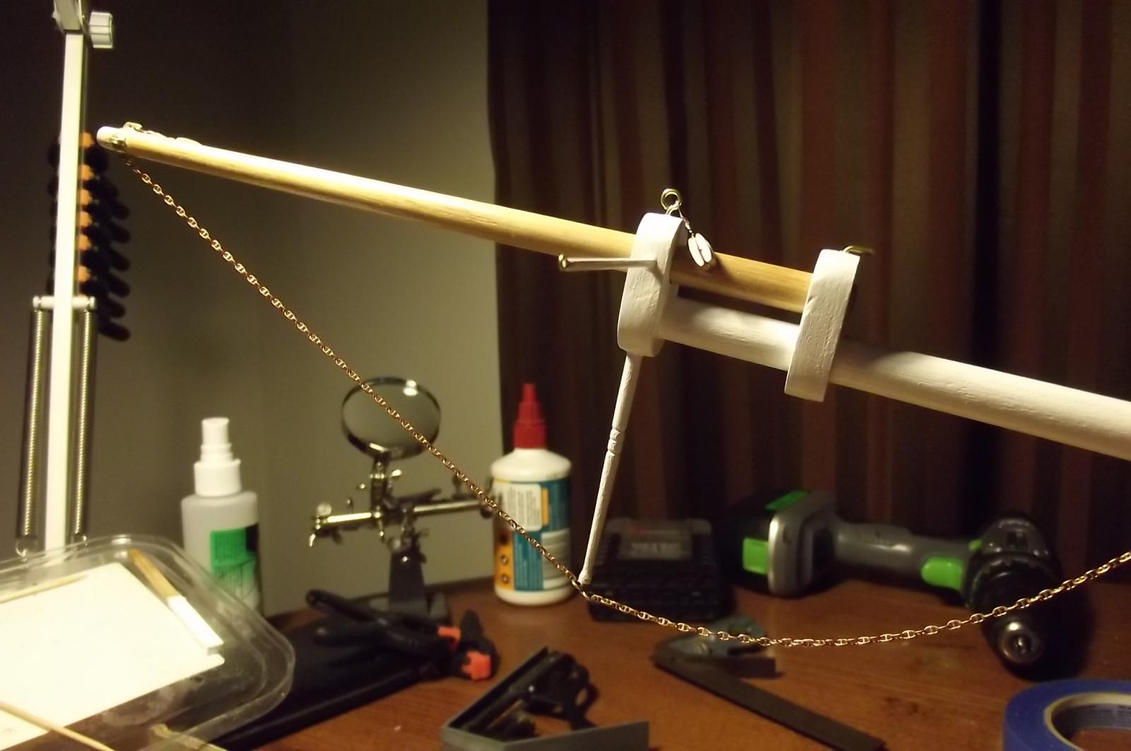
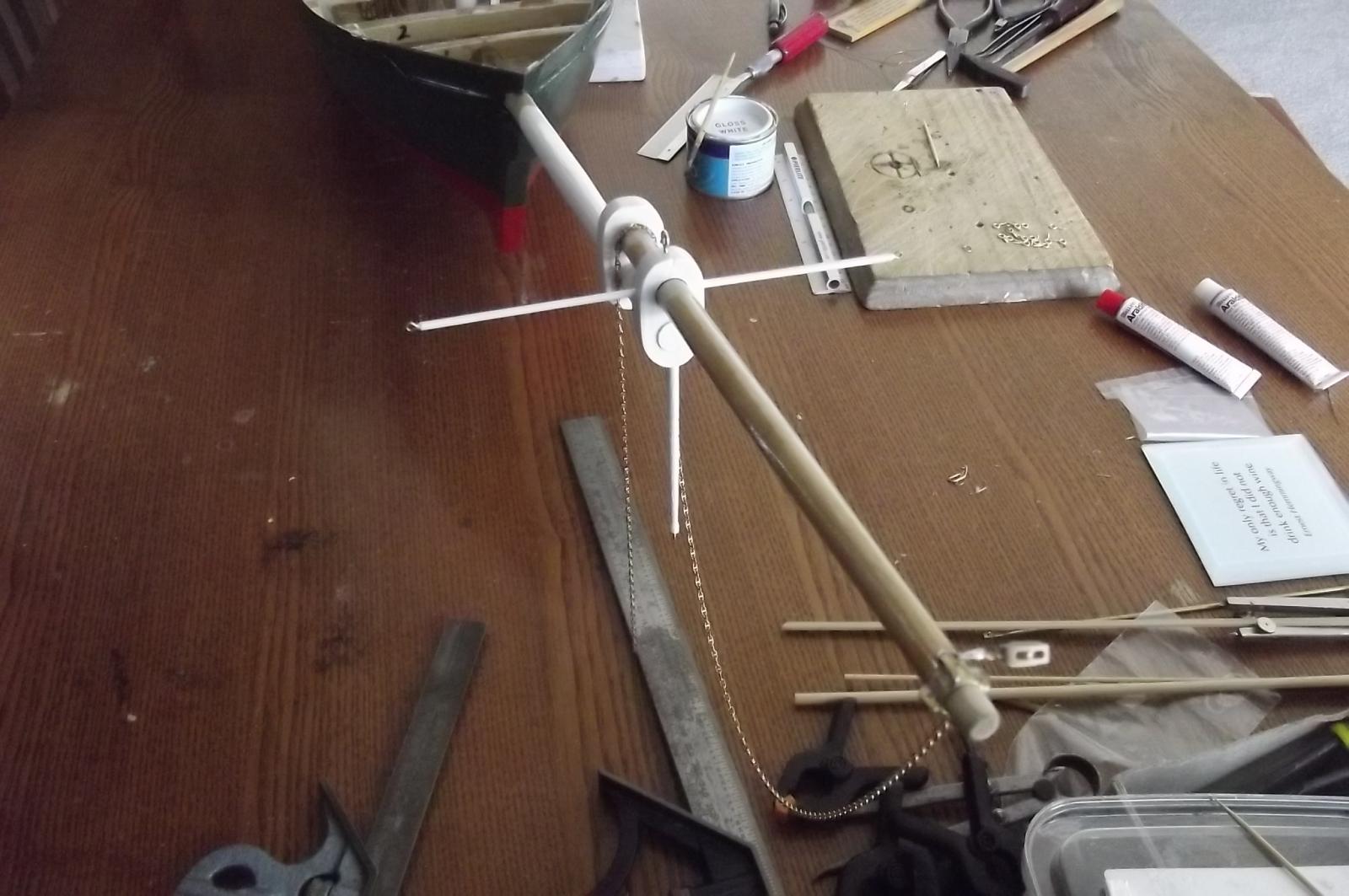
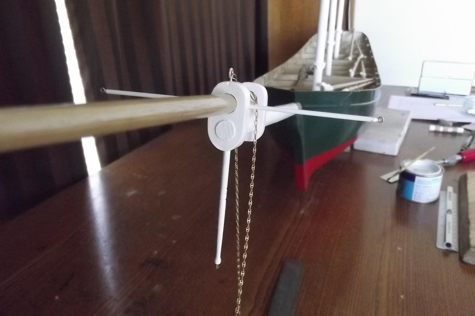
Not as clever as the stays'l sheets but a simple way to raise and lower the stays'ls without having to turn three different diameter winch drums.
Recap - all the sails on this ship are in lots of three and the course and tops'ls are basically the same relative to each other so one pull will handle the course and one for the tops'ls but the stays'ls are all different sizes and travel different distances up the stays so I was thinking I had to turn three different diameter drums for the one servo. These would stack one on top of the other and give the different rate of pull needed for each sail.
Better idea !
I know it isn't quite scale but then this is "stand off" scale.
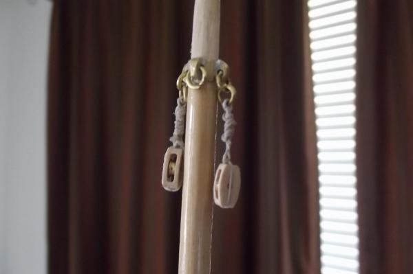
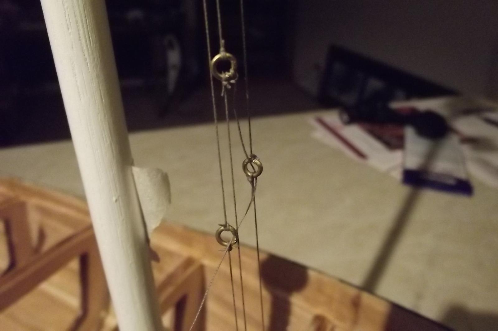
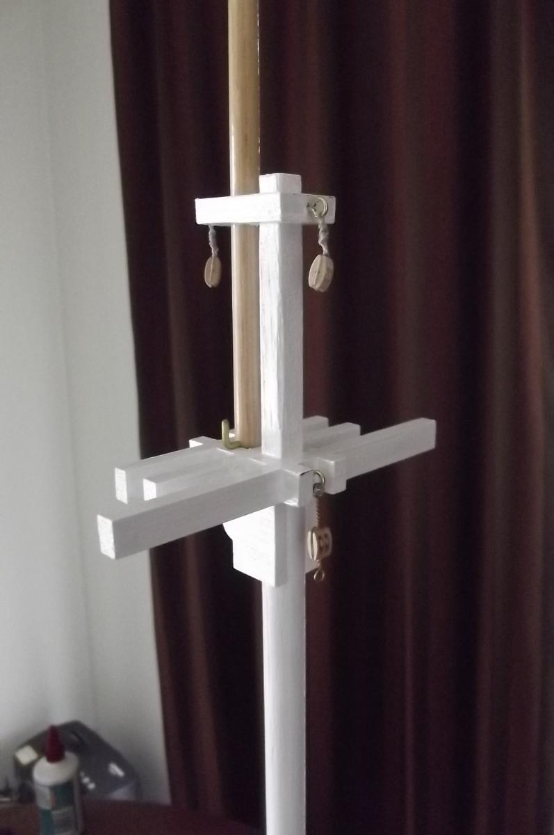
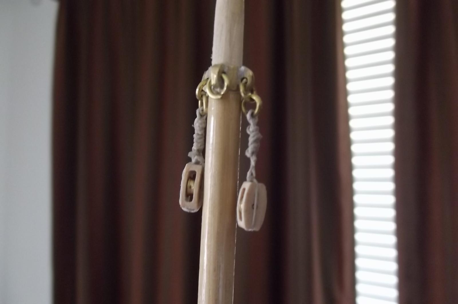
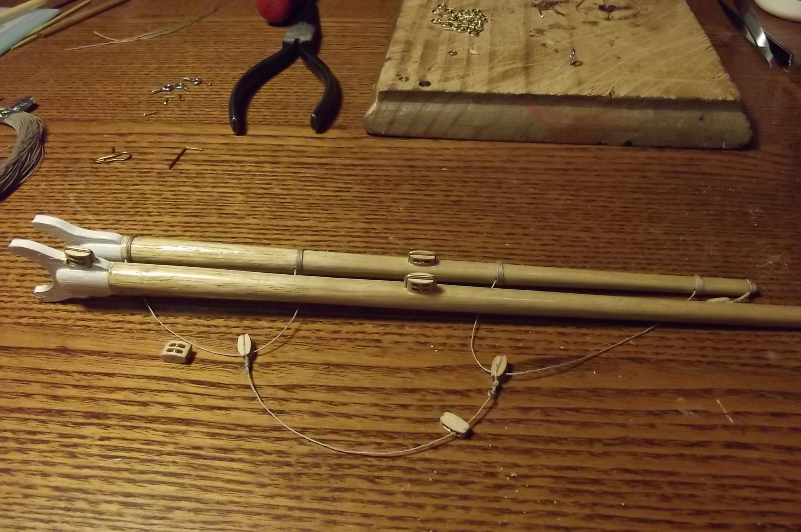
I tie a brass ring into the halyard for each sail immediately below the block on the mast.
The halyard/lazy jack forms a closed loop for the lower and upper stays'l and the halyard for the top stays'l runs through the rings on the other two and goes to the servo drum.
Therefore the top stays'l is the only one that is directly connected to the sail winch servo. As it is pulled down the ring in it catches the ring in the upper stays'l halyard and starts pulling it down and then catches the ring in the lower stays'l halyard and pulls it down. By setting it up with the rings in the correct place on the halyards they all pull down to the same spot and the sails raise to their correct height.
The trouble is going to be in lowering the sails because the rings won't pull the previous one up. I think a lanyard linking each ring at the correct distances will do the job. So the top stays'l halyard will go up the mast as the sail is pulled down, when the lanyard reaches it's limit it will start pulling the upper stays'l halyard and so on.
My only concern with the lanyard is that it may get blown around while slack and get fouled on the tressle or deck furniture. If this is the case I may need to use a chain for the lanyard because it won't blow around as much. Failing that I could put a small sinker on the lower ends of the lanyards to keep the thing tight. Time will tell.
First pic, the tape on the halyards represents where the top of the sail would be.
Lowered.
Raised.
You can see the ring with the halyard passing through it just under the block for the upper stays'l

With sails raised all three rings would be together just a bit above the deck.

Also.............................I MAY have something interesting to show tomorrow.
Steve
- mtaylor, Boodar, qwerty2008 and 1 other
-
 4
4
-
You are doing lovely work there Michael, I check this thread every time I log in.
-
Count me in Robbyn, I am back on board for this build.
Looks like you have made a good start.
Steve
-
Waiting for parts to turn up from the UK again.............
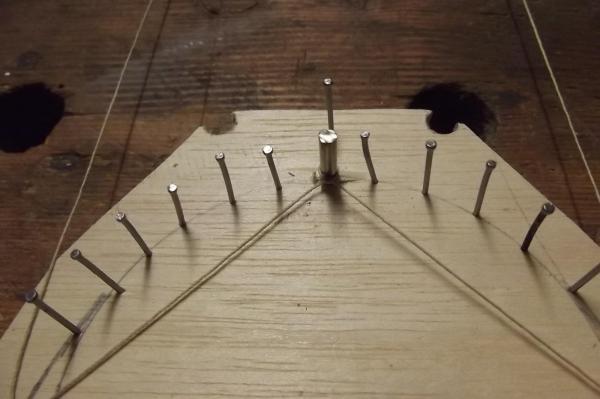
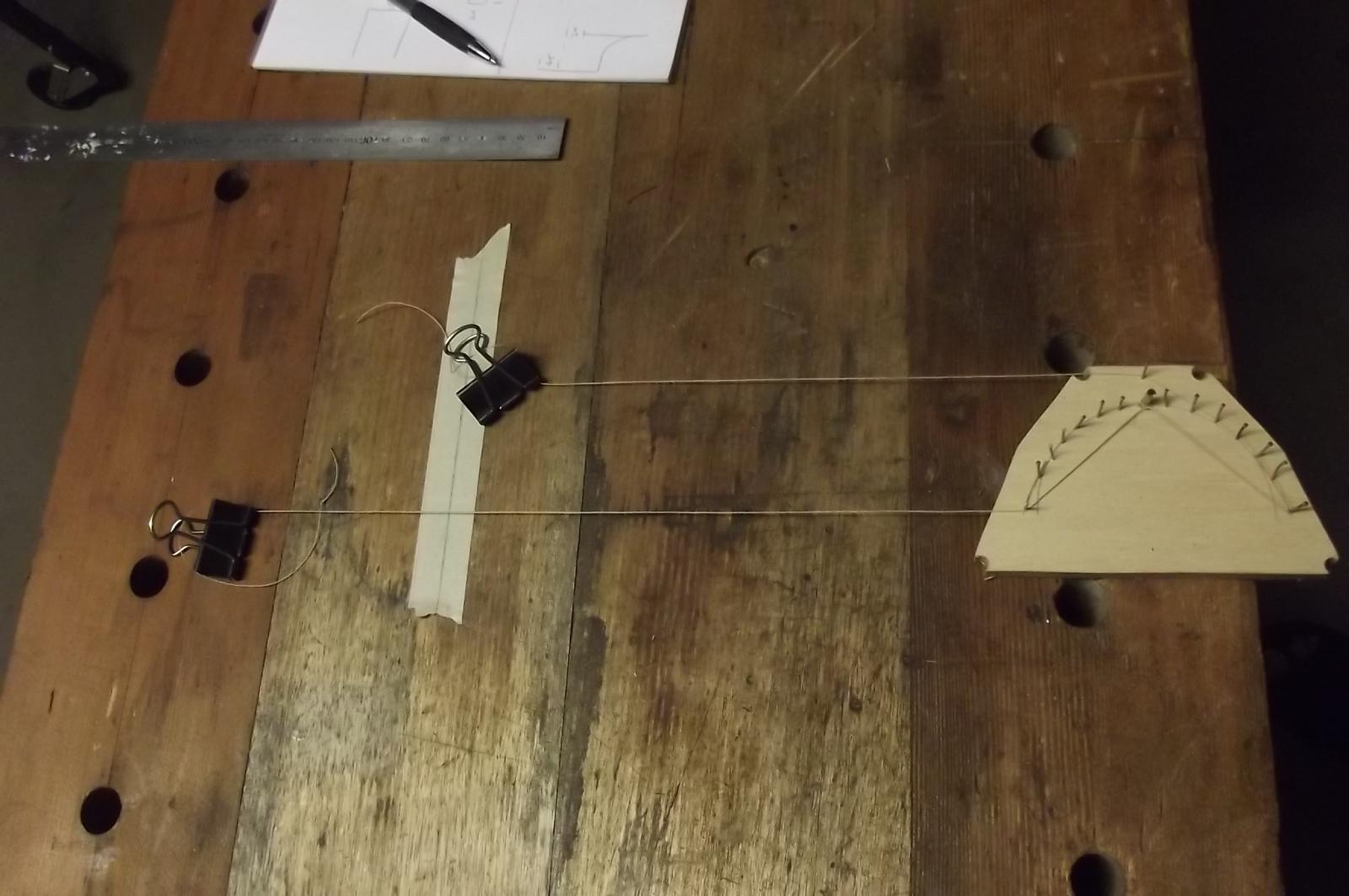
There was discussion on page 14 from memory about the difficulties involved in controlling the differential feed required for the stays'l sheets.
The problem is that as the sails cross the stay in the course of tacking the lee sheet has to take up while the windward sheet has to go quite slack so it can cross over the stay and remain slack. Therfore the servo has to let out more line than it takes in. This leads to some very complicated control movements as per the posts on page 14.
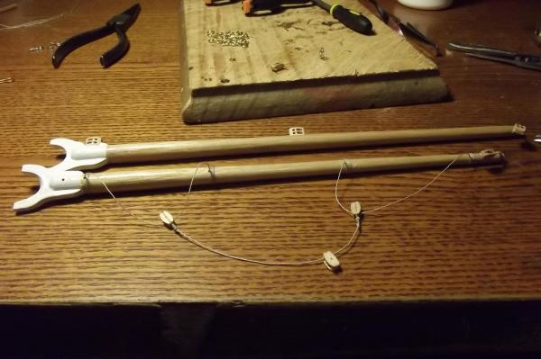
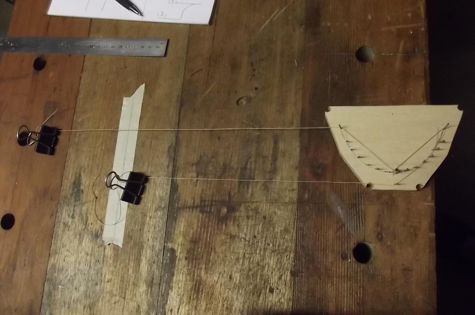
Me being me I always look for an easier mechanical solution. Tonight I found it !
This is going to get a touch technical but it is pretty straight forward.
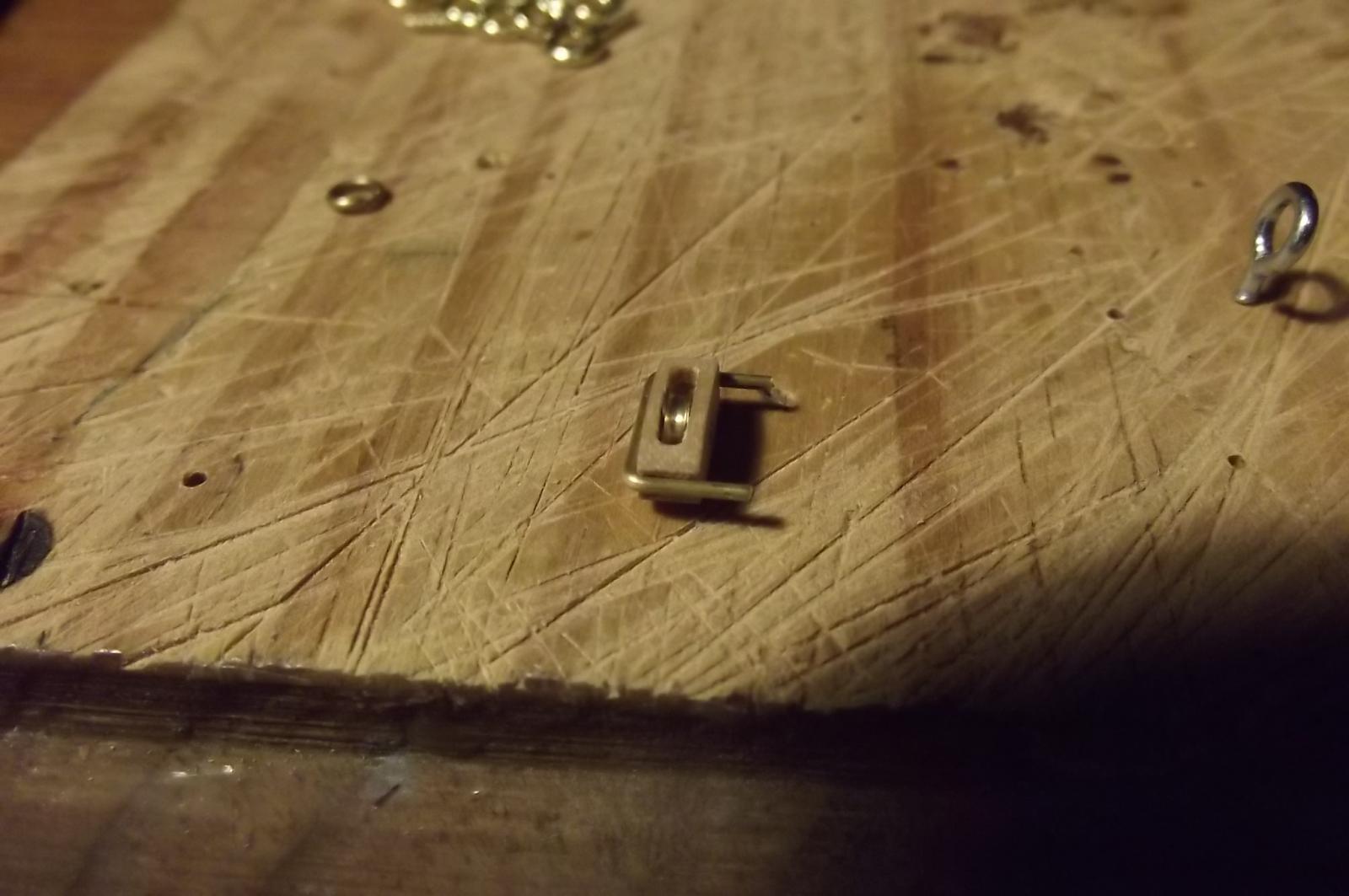
First, I have about 150mm of width in the fore cabin to play with and the device I made to test my principal is 90mm across so it will fit in easily. I was thinking I would need a curved sheet guide to provide smooth exponential in and inverse exponential out feed but it turns out that the rotary movement of the end point achieves this naturally. What I am saying is that I started with a curved line of nails but ended up realising that I just need to attach to the end of the arms, ie where the last nails are in the pics.
The large pin in the centre is the pivot so this is where it would attach to the servo, the lone nail out from the pivot pin adds to the inward pull.
Now that that's as clear as mud, look at the following pics, you can see the position of the clamps on the faux sheets when the control device is centred.
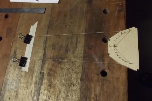
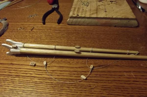
When the device is turned through 90 degrees you can see that the inward pull is significantly less than the outward feed.

The same occurs in reverse when rotated to 90 degrees in the opposite direction.

You can see how the sheet goes out around the single pin infront of the pivot. I would imagine making the centre of this pin adjustable so as to have adjustment of the in pull. The further from the centre the greater the pull.
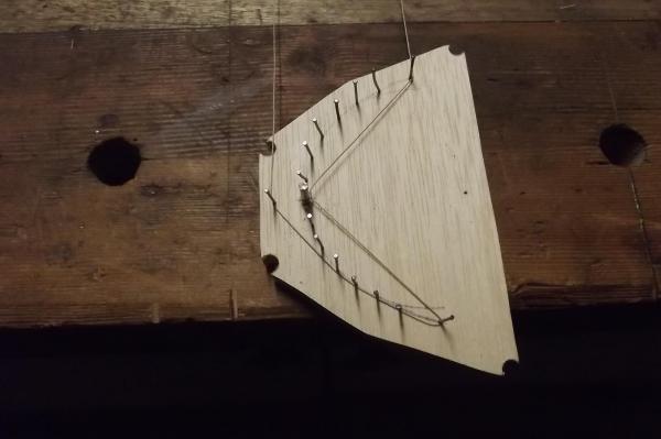
With the test rig I achieved a differential feed of 60mm, ie 30mm in and 90mm out!
So I need to buy yet another servo, one that will travel through 180 degrees, and make the "L" shaped servo horn with an adjustable pin, no biggy ! I will probably need to make a guide out of brass wire so that as the servo rotates and pulls in the slack sheet the guide will make sure it comes back up onto the servo horn.
If you followed all that, you win a banana !
Steve
- mtaylor, Elmer Cornish, KevinR and 1 other
-
4
-
Beautiful work Michael, it looks like a great scale to work in.
I have handled lignum vitae once, at the old Sydney Maritime Museum they had a piece of about 75mm square and maybe 600mm long. It is so heavy and smooth, unlike any other wood their is. I would love the opportunity to work with a piece of it.
-
-
What was said about the speed of the Victory after the battle of Trafalgar, she makes 10 inches to the hour?
I think I have built the Victory. I floated her in the bath and powered her up, after about 10 seconds of running she started to make way, very painstakingly slowly and bung the motors in reverse which is 50% the revs and nothing.
I wish the sites I bought the props and motors from had a chart to match things or at least more info on the props, when I got them the paperwork said their max rpm was 13000, I had an idea then that this setup would be woefully inadequate.
Next step is to either find two new motors to run without reduction gearing or find bigger props but what I didn't realise when I ordered the shafts is that 25mm is the biggest prop I can get to fit 3mm shafts. I think revs are going to be the answer, either that or I get two big plastic props to fit while sailing her but they would create a lot of drag.
I can remove the reduction gear boxes from the existing motors I suppose, rather than spending more money just yet.
Too late tonight so I will look into that tomorrow.
-
Thanks Bob
I aquired a battery charger today, damn thing comes with a book of instructions !
What happened to the good old days when it was just plug in - turn on ?
Assuming I can work it all out, including programming the radio, I will then have to find somewhere reasonably nearby to see how she goes.
Steve
-
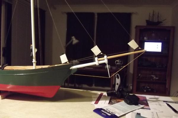
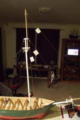
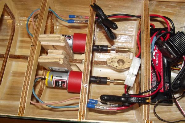
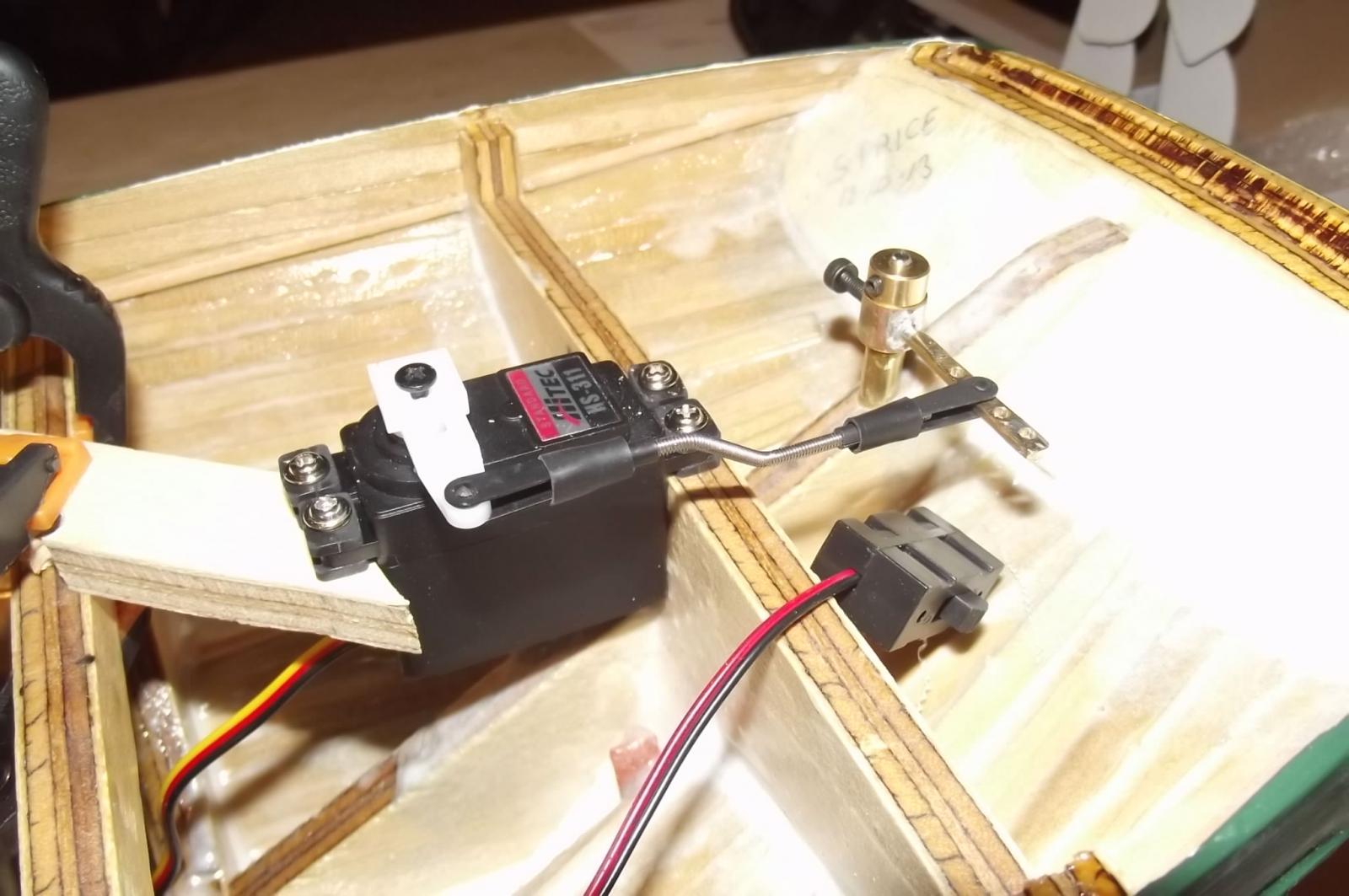
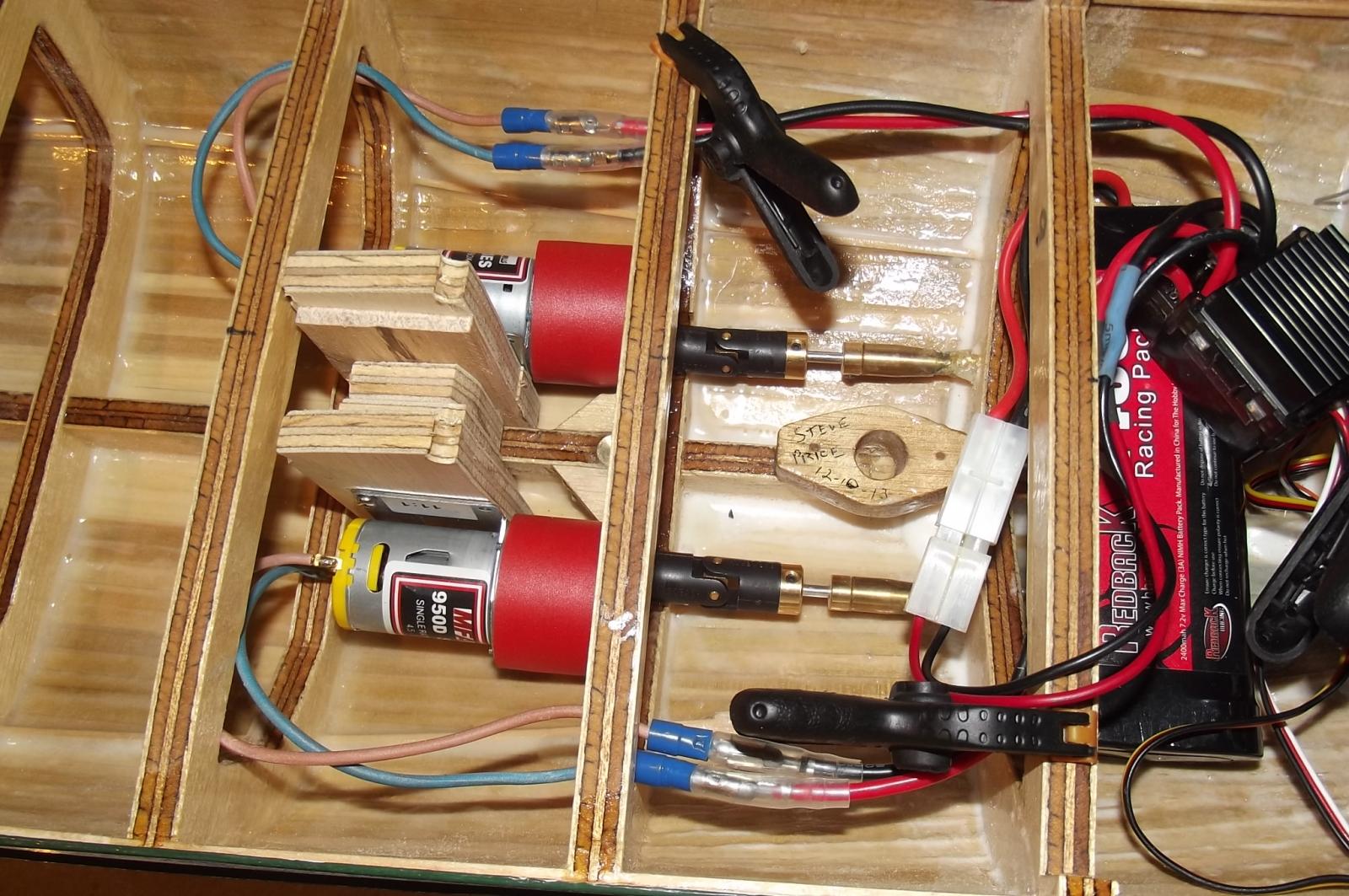
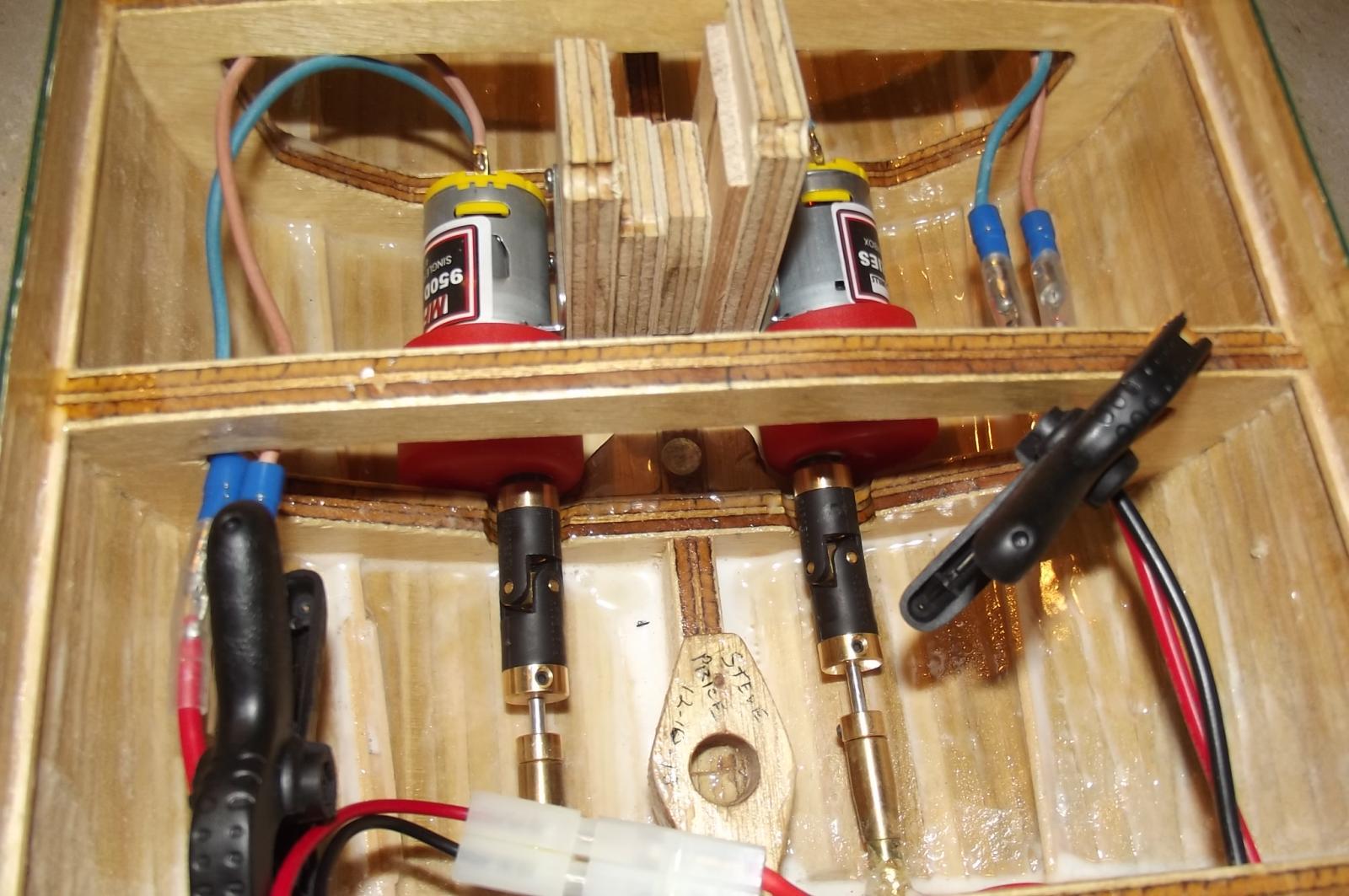
My goal this weekend was...............sea trials!
I set up the motors and made the steering arm etc but when I came to charging the onboard battery I found that my old charger has died a horrible death so I was unable to power it all up.
These pics show a real mess but it is all just jury rigged for sea trials. I need to see if the motor / prop combination will provide enough thrust before going much further.
Helm control with temporary servo mounting

Motors, battery and speed controller, temporary mess
The whole mess
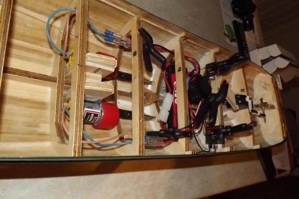
The motors, like everything else, are temporarily mounted.

-
I have to make the sails for my schooner, my wife was quite a good seemstress and had a very good sewing machine with feet for just about anything you could want to do. I should have built the schooner before the divorce

Now I am in your boat and have to do it myself.
Steve
-
Nils, we could jump ahead and look at the completed model in the appropriate gallery but that would be a huge spoiler. I am checking on this build every day to see what new pics you have put up. It is fascinating.
Such beautiful work and craftsmanship.
Steve
- clipper and Mirabell61
-
2
-
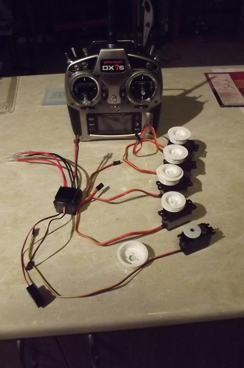
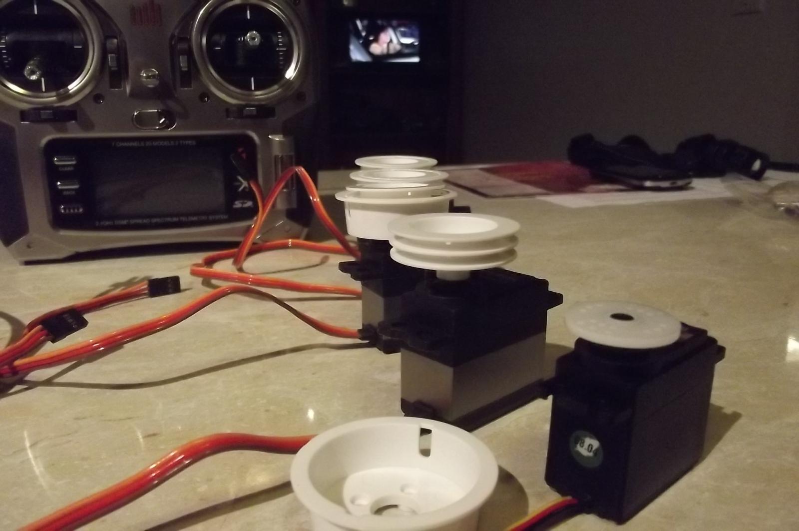
New parts have arrived in the shipyard...................now it really gets interesting

The winch servos look good and they are nice and heavy so hopefully that translates into strong!

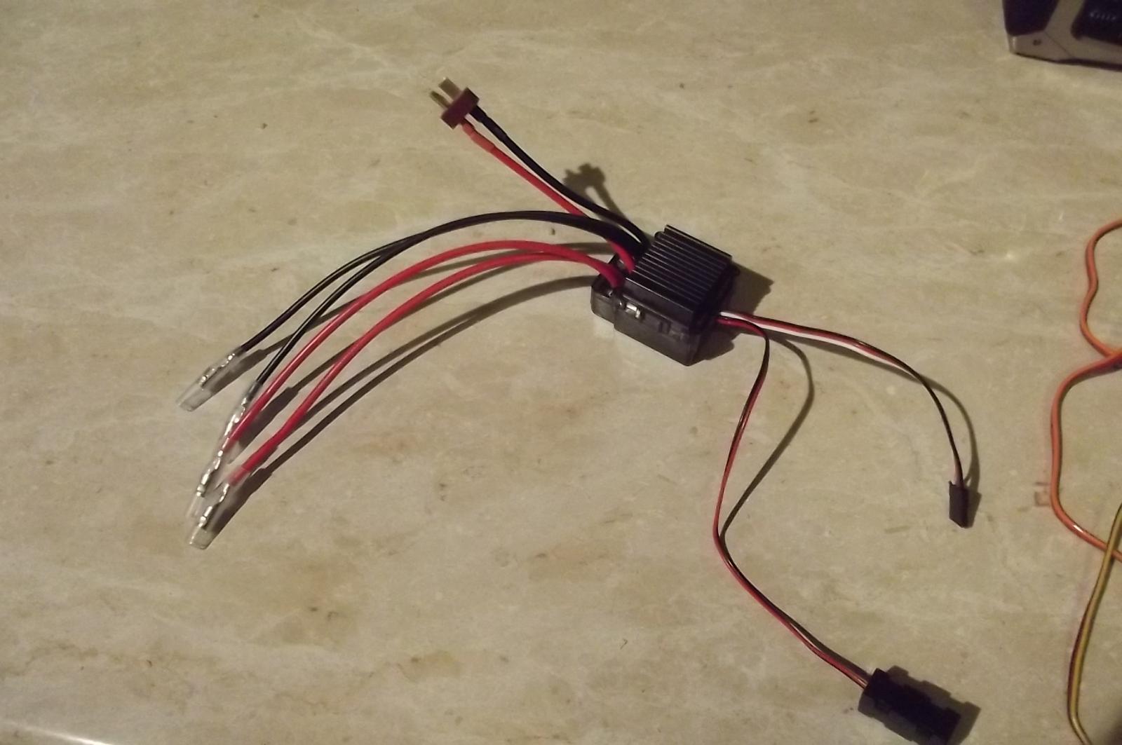
The speed controller for the motors is designed for a 4wd buggy with two motors, convenient!

Now to start planning the controls in ernest.
-
John, just a little note on the colour of the Craig when she was brought into the haorbour 20 odd years ago. I found pics the other day and she was a light blue and another colour, I think just whatever they could get cheap to paint over the rust and make her look a bit presentable. I first saw her on the pontoon dock next to the "South Stien" in Darling Harbour during the bi-centennial celebrations and she was painted brunswick green then.
Steve
-
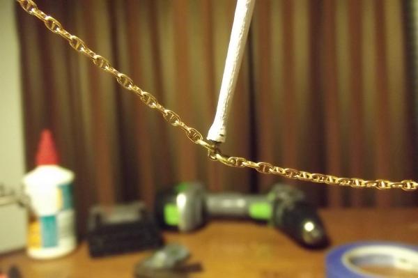
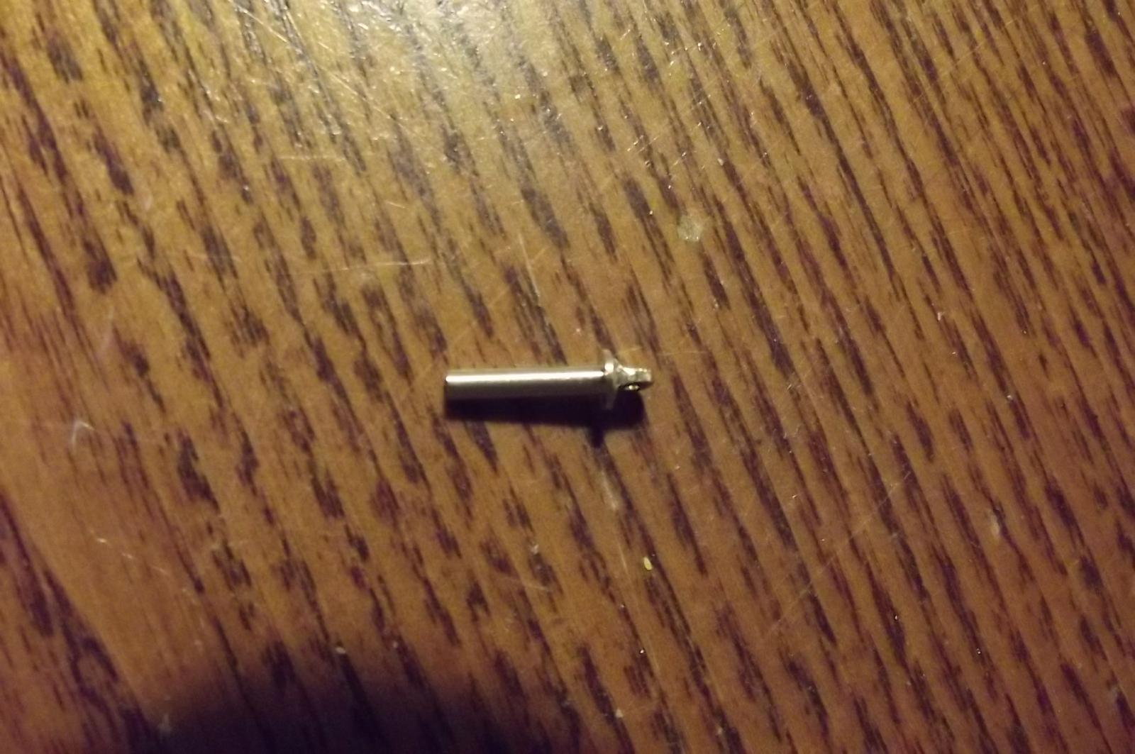
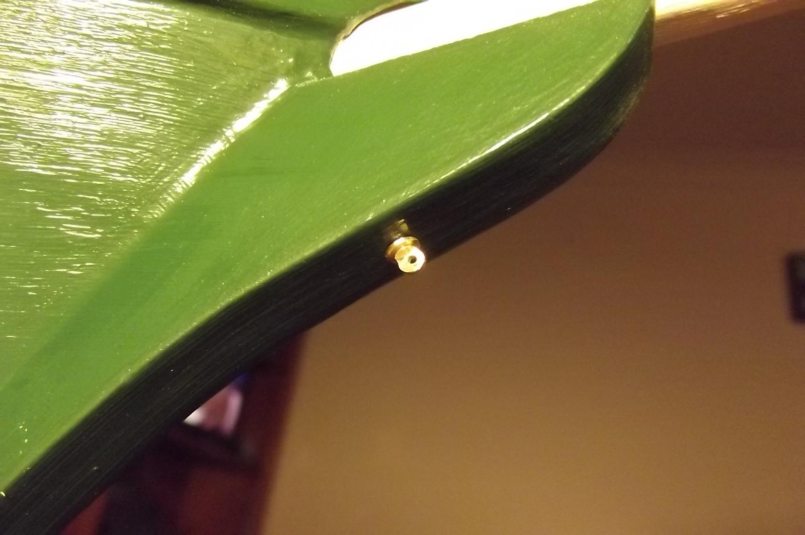
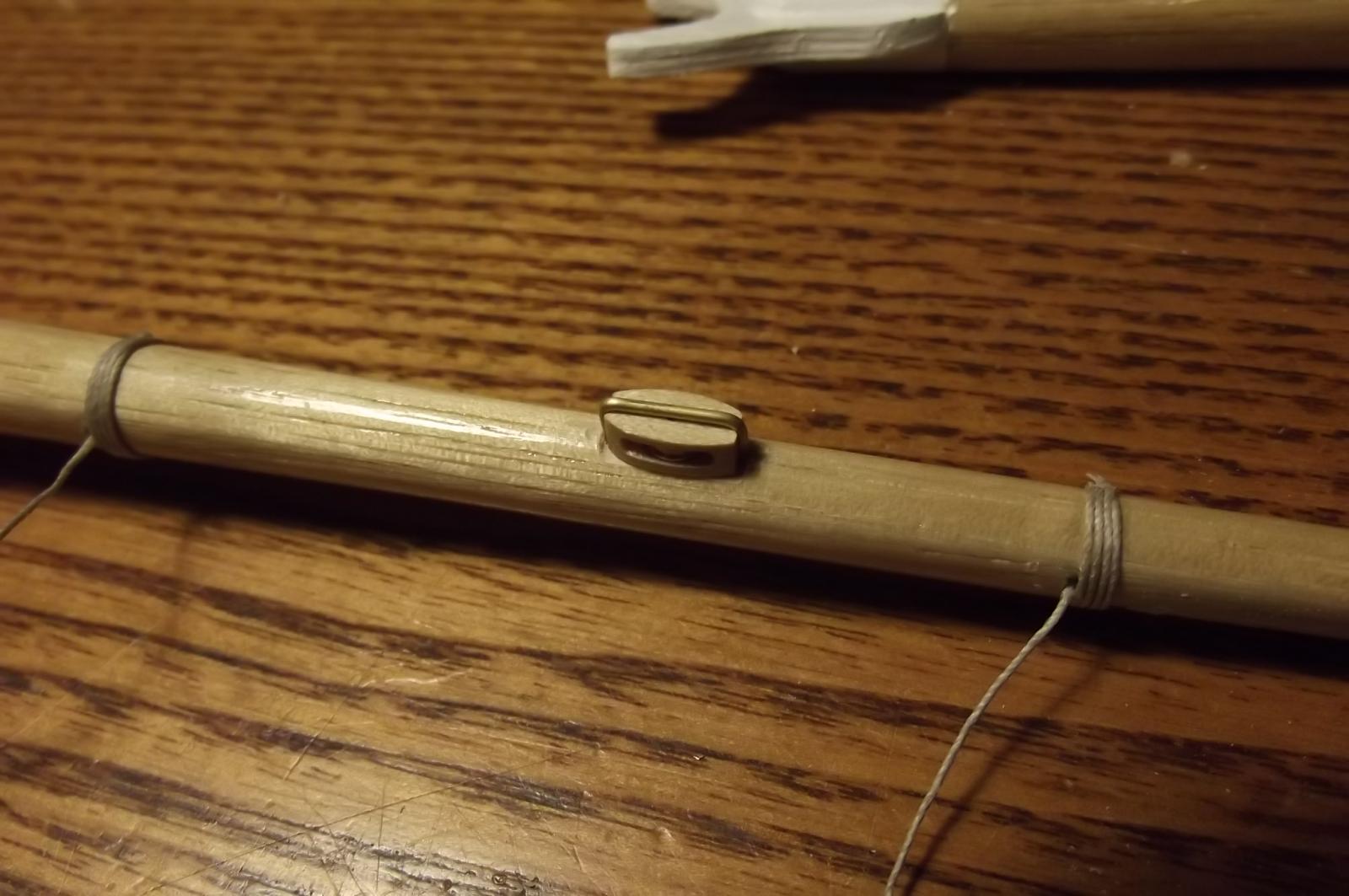
More progress, the chain is partially fitted and I have turned an eye with which to attach the other end.
The eye pin has a 2mm shaft, then the flange was turned to 4mm and the eye loop was formed by filing.


- mtaylor, JerryTodd, avsjerome2003 and 2 others
-
5
-
I find myself more and more getting bogged down with planning and details to the point I sit and stare at her thinking about how to do this and that and not actually achieving much. This weekend was considerably cooler thankfully and it rained, I had heaps to do around the house because I had been too tired from the heat to do it. I got all caught up and decided to just do SOMETHING to the ship and what do you know? Some of the things I had been agonising over just happened.
First, I can't remember what I was thinking when I glued the eye collar onto the dolphin striker that made me put the eyes at 90deg to the bowsprit ( I'm sure there was profound logic behind it at the time ) I ended up cutting it off and drilling up the center of the timber to accept an eye pin so I can attach a chain from the end of the bowsprit jib boom via the striker to the bow. Then I looked at the line of the horizontal stays for the bowsprit and realised I needed to stand them off so as to allow free movement of the anchors so I added the timbers to do that.


The chain is a studded anchor chain, I have used this because the normal brass chain with open links has a certain amout of elasticity. This is a closed link chain and will take the strain.
The strain has been a big stumbling block, ie:- will it last, will it hold, do I need to design something better, these questions are comming up for everything I do now but I have decided to just build it soundly and if something does need to be re-engineered stronger it will let me know.
I am doing the rigging for the blocks in a simple yet strong way by twisting 0.5mm cord together leaving an eye which I then pass the ends through to form a loop into which goes the block. The block is then placed over a pin on my cutting board and the tail is passed through an eye hook screwed in about 12mm away. I then run the tail up beside the block and clamp it there and use another piece of 0.5mm cord and tie it around the tail, knot after knot all the way up to form pseudo siezing, I cut the ends of the tail a bit short of the block so they get covered by the siezing and when all is done I put glue on my finger and thumb and squeeze it into the rope while rolling it between my fingers. Some are not very neat, they were done when I should have been in bed.
 They will not stand out in the overall ship though, especially when she is under sail.
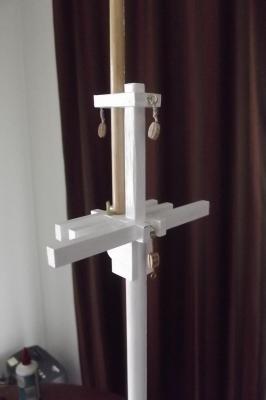
-
Well I have been a bit quiet lately, mainly because of the heat and all the planning, it has left me a bit brain fatigued.
Orange is a place that can get snow in winter and normal summer temps are in the order of 26 to 28 deg C with the odd day of 30 ( that's 79, 82 and 86 degrees respectively for the imperialists) but the last two weeks or so have been up around 33 and 35 deg C or 95 deg F and thats just too much for me because I never did handle heat well.
The upshot of all that is that when I muster the energy to work on the ship I only do what I can without leaving the air conditionned comfort of my house and entering the stinking hot garage.
Tonight though the temp has dropped and it has rained, and we really need that because most of the country is in drought, and it looks like a few nice days comming up.
So, to the progress.....
I am working on the blocks etc, fitting them to the masts, booms and gafs.
I created a flat on the side of the booms and gafs to accept the blocks and glued them on with a simple butt joint but I wasn't happy that this would be strong enough.
So I drilled into the boom/gaf at each end of the block and bent up brass wire which I epoxied to the block and into the boom/gaf and I feel much more confident now.


-
Again, if memory serves, I seem to remember reading about her at the Sydney Maritime Museum - not to be confused with the Australian Maritime Museum in Sydney - that she was trying bulk loading for the first time like the non sail ships did and had a hold full of wheat. She encountered a storm and the hatches were letting water in. The grain on the leeward side of the hold became saturated which caused her to heel over more and the fact that the grain was free to move around in the hold meant it all tried to get to the lee side and she capsised.
I was there not long after the James Graig was brought to Sydney so that was about 20 years ago, I will therefore stand correction

-
From memory she used to frequent Sydney along with her fellow "P" line ship, the Passat. Not sure which but one of them was the last commercial tall ship to sail out of Sydney on 1957.
I will keep a close eye on this one.
- avsjerome2003 and Mirabell61
-
2
-
More and more I am loving the old schooners.


Maine three masted schooner by Bedford - Radio - 1:54
in - Build logs for subjects built 1851 - 1900
Posted
Happy to say she remained as dry as a bone throughout the test.
It appears that the coupling on the motor shaft was a bit too close to the motor and under thrust conditions it rubbed on the motor itself causing it to bind up. This led to a high current draw from the motor which in turn burned out the battery lead before any other damage was done, thankfully.
I have re-attached the coupling and replaced the lead and all is well.