molasses
-
Posts
455 -
Joined
-
Last visited
Content Type
Profiles
Forums
Gallery
Events
Everything posted by molasses
-
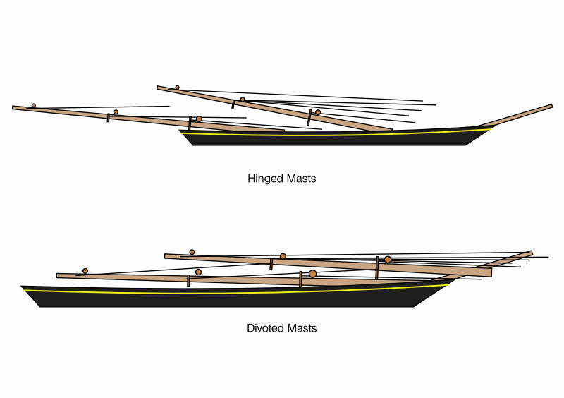
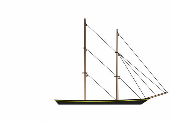
 You can rig all the shrouds and backstays outside the bottle but you won't be able to set the masts into a hole or tube. You can use either hinges at the bottom of the masts or use one of two variations on what I call the "divot" method. For this just drill a very shallow hole - just up to the shoulder of the point of a bit the same diameter as the mast - leaving a shallow "divot" to locate the base of the mast. The base of the mast has a matching shallow cone to fit into the divot. Glue a length of thread into a small hole drilled in the center of the mast base and pass this thread through a small hole drilled through the hull at the center of the divot to draw the base of the mast into the divot. The thread can be omitted if you don't mind guiding the mast into place with a tool from outside the bottle. I've used both variations but prefer the thread when there are deck obstructions. It is possible to rig an entire vessel outside the bottle and pull the masts out of the divots which will collapse the rigging like pulling out the poles of a pup tent. Inside the bottle, all that is required is to move the bases of the masts back into the divots. However, this method requires clear space forward of the mast locating divots to allow the mast bases to slide on the deck into position. Having some fore-and-aft stays loose will allow moving the mast bases into the divots around or over obstacles. Conventionally, all of the fore-and-aft stays (six on the foremast, four on the other four) will have to be routed out the bottle - 14 to 22 total, depending on how they're rigged. Here's three sketches of what happens to the fore-and-aft stays. A brig with three yards on each mast, other spars (spanker boom and gaff) and all rigging but the fore-and-aft stays have been omitted. There are two variations on rigging these stays. First is to have the main topmast stay (middle one on the aft mast) route through the foremast (where it becomes the forestay) and through the deck. Similarly with the main topgallant stay (the upper one) through the foremast (where it becomes the fore topmast stay) and through the bowsprit. You won't be able to glue the fore topmast stay sail to the stay, it will have to slide on that stay. The alternative is to rig the main topmast and topgallant stays more realistically by passing the stays through eyes glued to the aft side of the foremast and down through holes in the deck and out the bottle. They can be routed through the same hole as the mainstay. Of course, all the forestays start on the foremast and go out through the hull and bowsprit in this variation. Here we have the two variations on masts. The upper has the bases of the masts fixed in place by hinges. The stays are all the same length as those on the first sketch. Notice how much more line will be needed in order for the masts to fold down. If the stay continues through the foremast then the shortages are added together and it also shows why many staysails can't be glued to the stays when continuous stays are used. The lower sketch has the mast bases loose. It seems possible to attach the stays at both ends to the mast and deck as shown but I would plan for the stays going through the bowsprit being control lines. On a five-master, the main mast stay(s) going through the deck may need to be loose as well. This could cut the number of stays out your bottle down to six or eight, maybe ten. I've never tried the divot method (with none of the stays being control lines - re-erecting a tent with only the tent poles) on more than two masts. I've learned that Murphy takes special interest in ship bottling and I prefer having options when - not if - something doesn't go as planned. If you're intending to rig the shrouds and backstays loose and draw them with the pull of one string, it would depend on 150 tied and glued knots not failing. You would need to glue off all of those threads individually inside the bottle to make sure the standing rigging doesn't go slack if any of those knots fail with time. Depending on how complete you intend to rig Preussen, I see eight or ten control lines in the fore-and-aft stays and two control lines for the spanker boom. Braces, yard halliards, topping lifts, clew lines, bunt lines, leech lines, reef tackles, etc. can be rigged outside the bottle and won't need adjustment inside the bottle, with a few exceptions such as tacks (and those are easy in the bottle but rarely done). I don't see any point in doing up-hauls, down-hauls and both the sheets on all the stay sails (and much of the listed running rigging) on a model of Preussen that isn't much longer than a pen. You're going to have a problem keeping the diameter of the rigging to scale; simplifying the rigging somewhat will help balance over-size lines. Even the finest fly tie thread is grossly out of scale for stay sail lines and many other small lines.
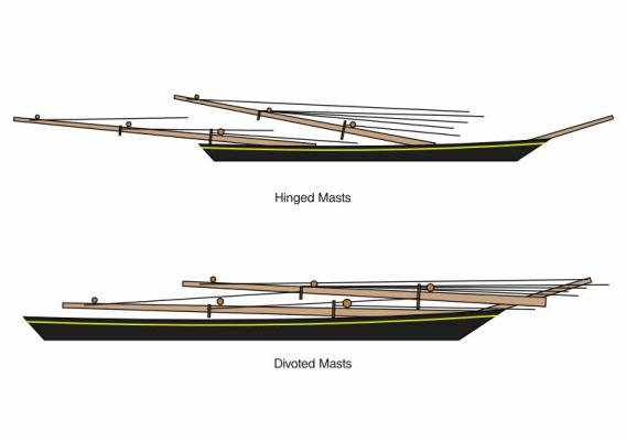
-
Deadeye Diameter and Thickness based on Shroud Size?
molasses replied to molasses's topic in Masting, rigging and sails
Granted; just like everything else on sailing vessels, there was an evolution, but that formula works well for late 18th century through 20th century wooden blocks for hemp rope. My project is a Napoleonic era warship. -
Deadeye Diameter and Thickness based on Shroud Size?
molasses replied to molasses's topic in Masting, rigging and sails
Thanks, John. That was what I was looking for. The diameter correlates pretty closely with what I was getting by scaling off the drawing depending on whether I measured to inside, outside or center of the rather fat lines on my drawing - 12 to 15 inches for 9 inch circumference shrouds but not close enough for sure. Thanks again to all. Dave -
I have a set of plans and pages of tables for all the rigging used on a ship I want to model. Problem is that there is no mention anywhere of the dimensions (diameter and thickness) of the deadeyes. I could measure the deck level deadeyes on the hull plans, but that's not reliable and doesn't help with the top mast and topgallant mast deadeyes. Is there a formula relating the deadeye dimensions to the size (circumference or diameter) of the shroud or back stay that will be attached to it? I know the three holes will need to provide clearance for a lanyard about half the diameter of the shroud. I already solved a similar problem with the blocks which don't have their sizes listed either, by using a simple formula. The sheave thickness is 1.1 times the rope diameter and the block dimensions are multiples of that thickness: length, 8x; width (across the cheek), 6x; and thickness (through axle), 4x and add two sheave thicknesses (one each for the sheave and spacer) for double, triple, etc. Seems to me that deadeyes would have an even easier formula.
-
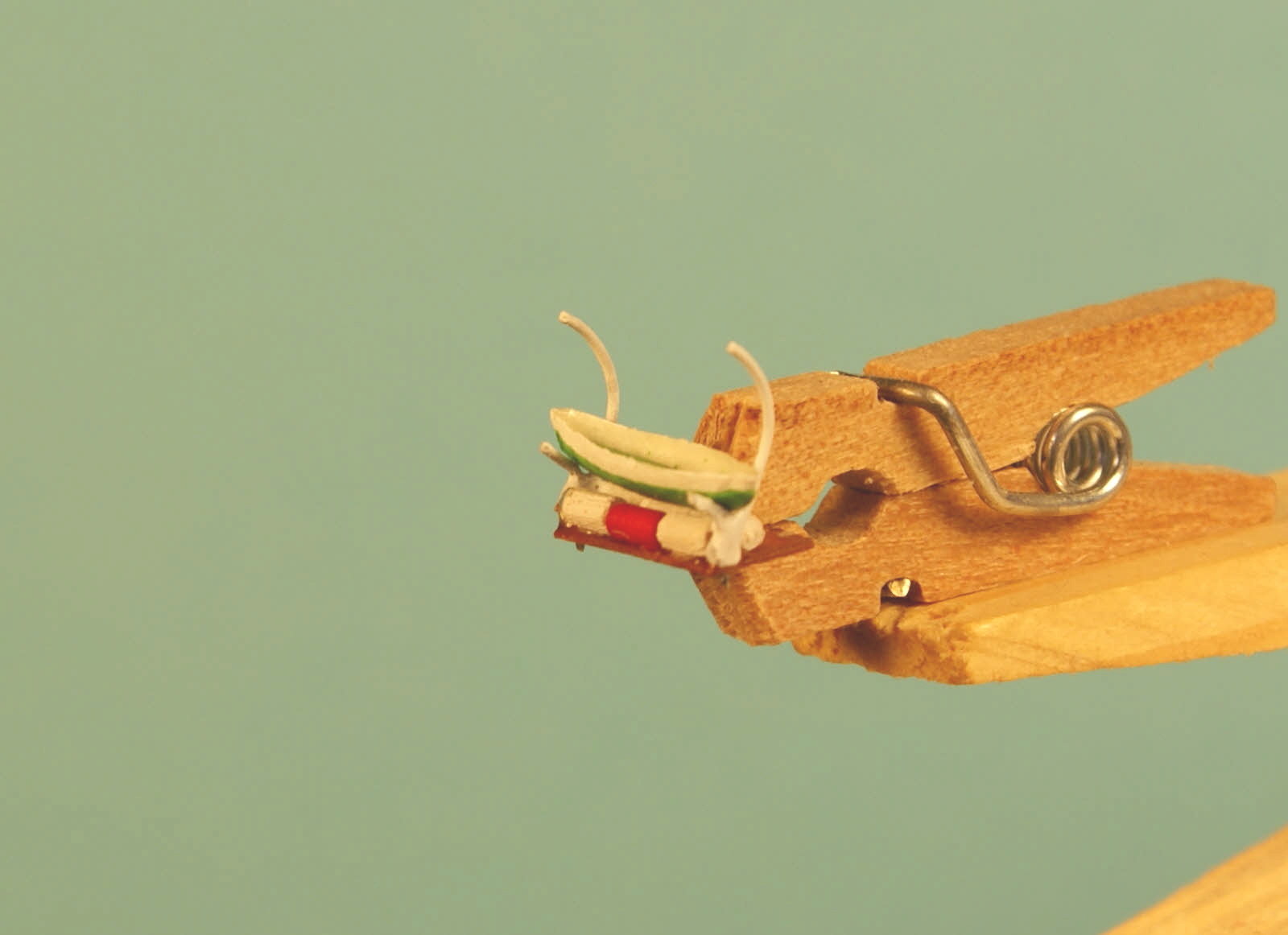
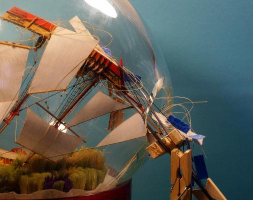
Jeff, If you look closely you may notice three sizes of clothespins. Here in the States the mini clothes pins can be found at Walmart in the craft section and the small ones in the office supply section. It seems strange they are in different sections but they are.
- 84 replies
-
- 1
-

-
- bottle
- training ship
- (and 1 more)
-
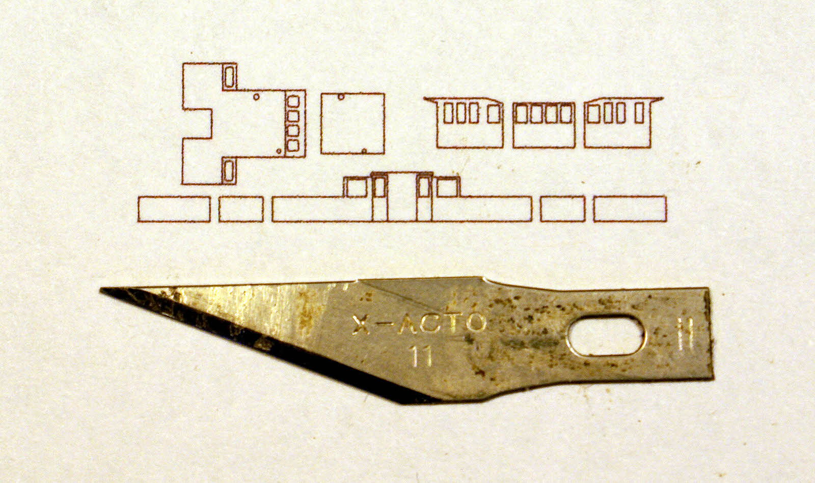
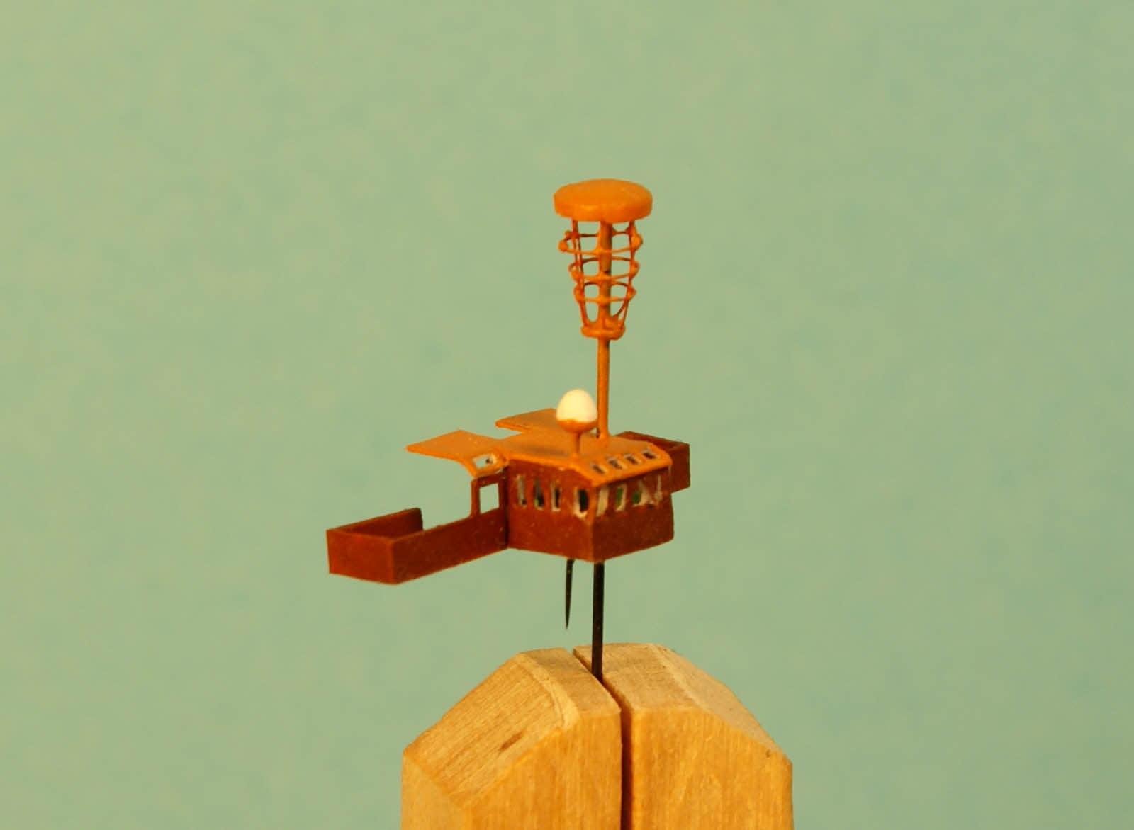
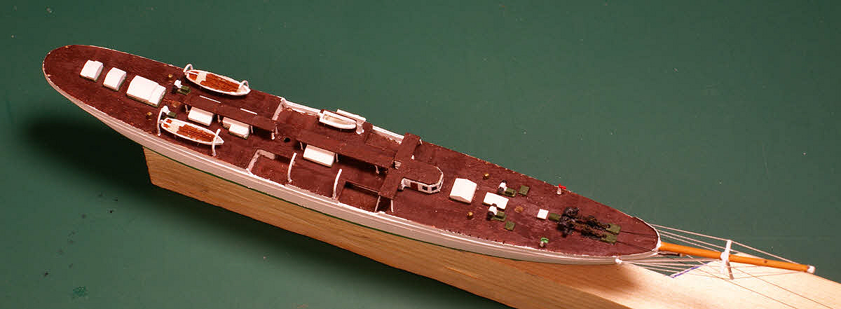
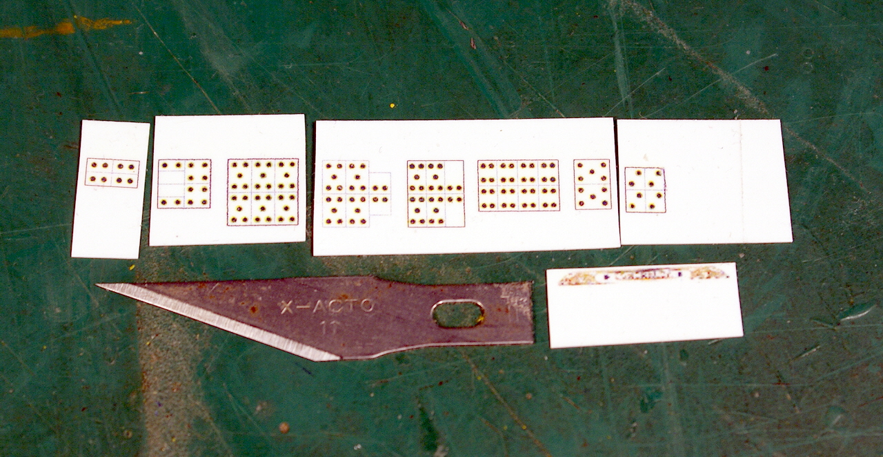
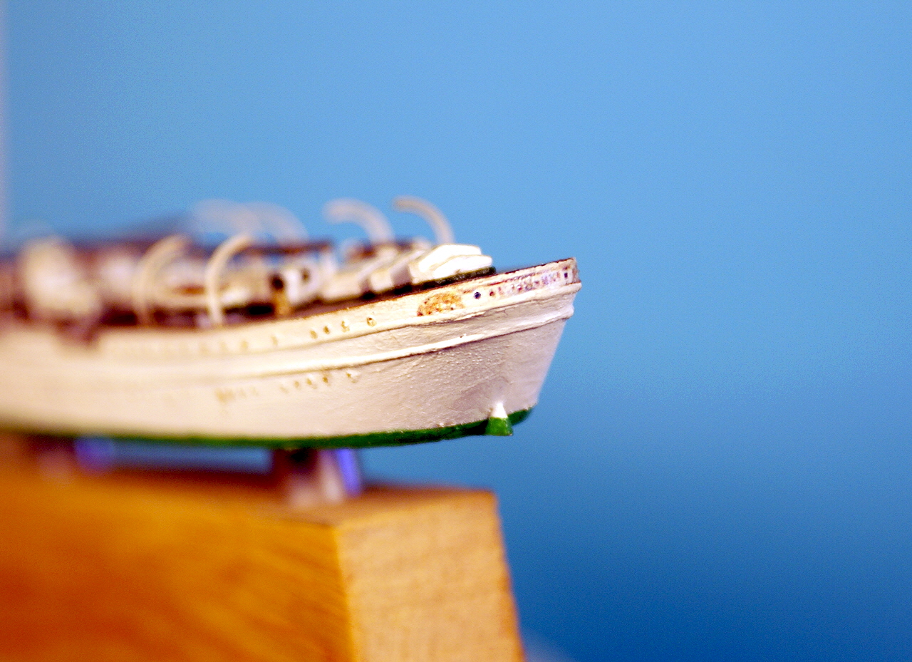
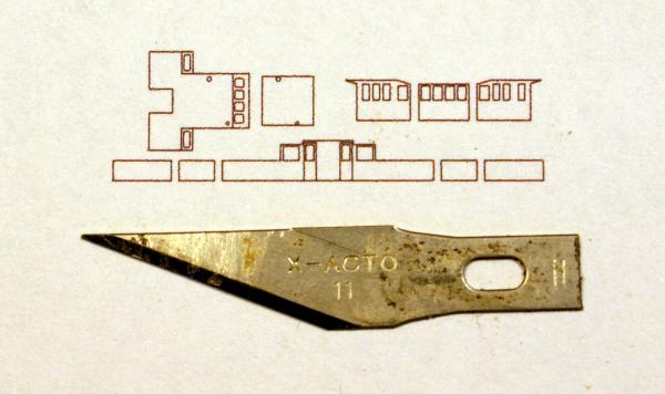
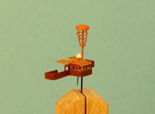
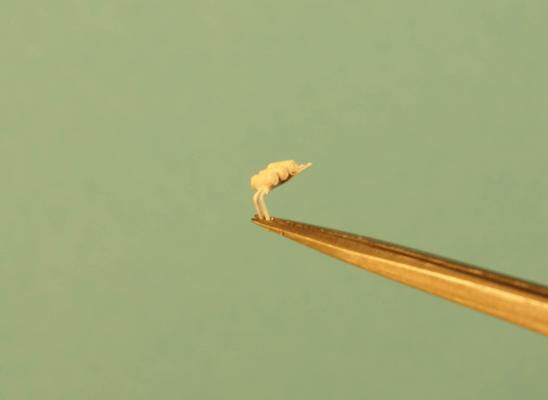
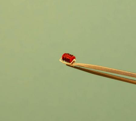
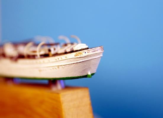
Time to post some progress. I'm basically focusing on deck details near and on the lower bridge just forward of the main mast. The flying bridge with radar units on roof and the boat with davits and containers below the boat. I drew the components I needed for the flying bridge on the computer and printed them out on card stock. Flying bridge parts with X-acto blade for size reference. Yes, I freaked out seeing them life size and wondering how I was going to cut out all those windows (22). But I surprised myself and all went well. Mostly complete flying bridge. I made the radar cage from 40 gauge (.0035 inch / 0.09 mm) wire with top and bottom made from a narrow strip and two discs of card stock. Other radar is a bug pin with the head built up with a couple dips in gesso. The roof of the lower bridge has two holes drilled in it to receive the two pins which will be cut shorter later - they are much too useful now as handles. Some detailing remains. I worked on the davits, boats and containers as single assemblies on bases from paper. This is essentially the same as on the ship (except the base is a thick steel plate) and works out well for me. Six containers, two davits and a boat. The containers were made from basswood sanded to diameter then cut off to length. I made lots so I could use those that were closest in length, even a couple thousandths difference in length at this size is noticeable. Davits and cradles made from 30 gauge wire. Boats were made the same as the others made earlier. The boats need thwarts, oars, rudders and tillers. These three assemblies will be glued to their places after the ship is in the bottle. At least that's the plan. I may be able to install the boat & davits assemblies before but I won't know until later - it seems better to plan for the worst case at this point. I also made two of these racks with three more containers each. I've assumed these containers hold inflatable life rafts - sixteen total. One of three fire hose reels on deck. Here's the group photo including the motor launch at far right which is now just a painted hull needing floor boards, seating, motor compartment, tiller and rudder. Dave


- 84 replies
-
- 7
-
-
- bottle
- training ship
- (and 1 more)
-
Where were you two and a half years ago? I'm at 95%+ done fabricating with only deck details left. And I do not want to find that I have a bunch of mistakes to correct. Seriously, Igor, I appreciate the offer but I really don't need them.
- 84 replies
-
- 2
-
-
- bottle
- training ship
- (and 1 more)
-
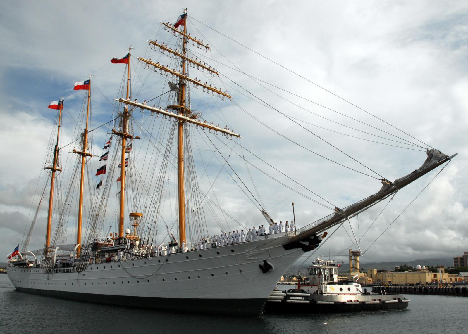
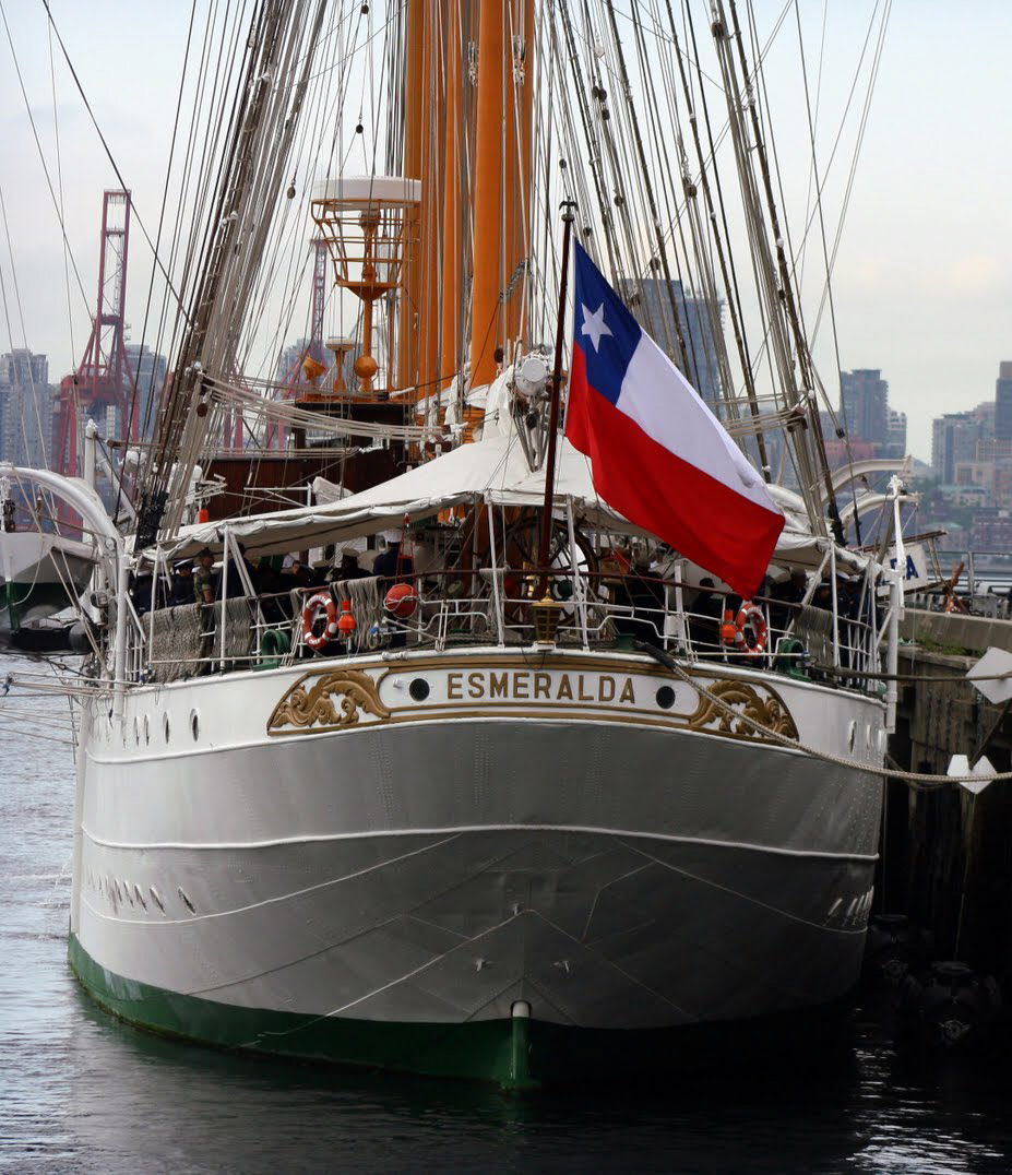
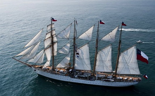
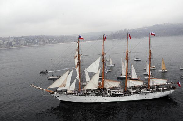
If you liked that shot you'll love this one: 300 crew + 90 Chilean Navy midshipmen
- 84 replies
-
- 2
-
-
- bottle
- training ship
- (and 1 more)
-
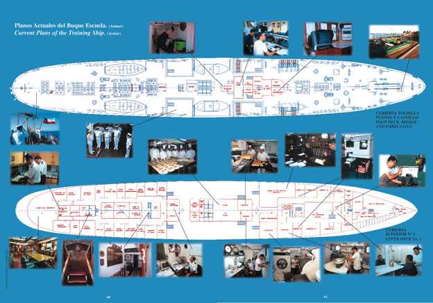
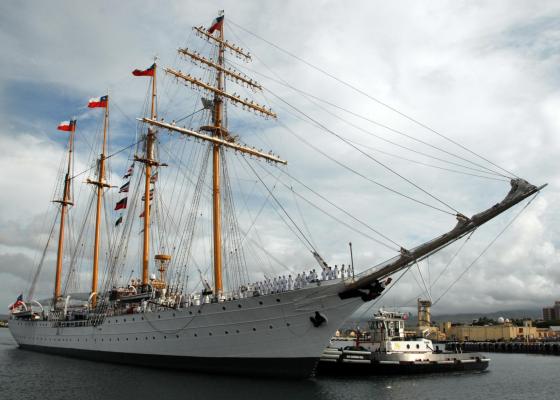
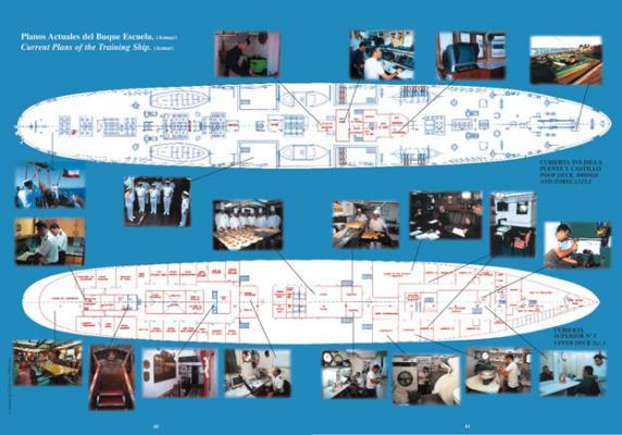
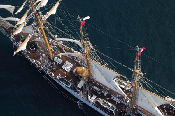
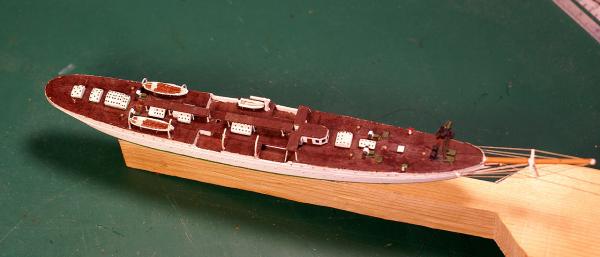
I'm working almost exclusively from photos. I was unable to find any plans for Esmeralda or her sister ship Juan Sebastian Elcano. I did find a low-res drawing of the weather deck and the deck below which gave me my deck outline and helped with my best guess at the waterline shape. I also had the dimensions (OA length, WL length, beam, mast heights, etc.) which I used to extrapolate other dimensions from the scores of photos I collected from the web. Deck plan used. The lower deck shows the hull shape at the lower deck which I used to make my best guess at the waterline. The three images below are lower-res versions (for posting here) of high-res images (up to 6 MB) I found and used for my deck detailing. I also used numerous on-deck photos and video tours of the weather deck for specific details and as checks against my extrapolated dimensions. In most cases I have two or more photos of a specific detail from different angles. Spar dimensions were easy to derive; there are numerous photos of Esmeralda under sail in which the spars are parallel or near parallel to the plane of the camera lens. It's easy to compare that length to the WL length or the total mast height in several photos to come up with a number at E's scale (1/640). That's my long answer. My short answer would have to be, "I'm eye-balling it." Dave
- 84 replies
-
- 4
-
-
- bottle
- training ship
- (and 1 more)
-
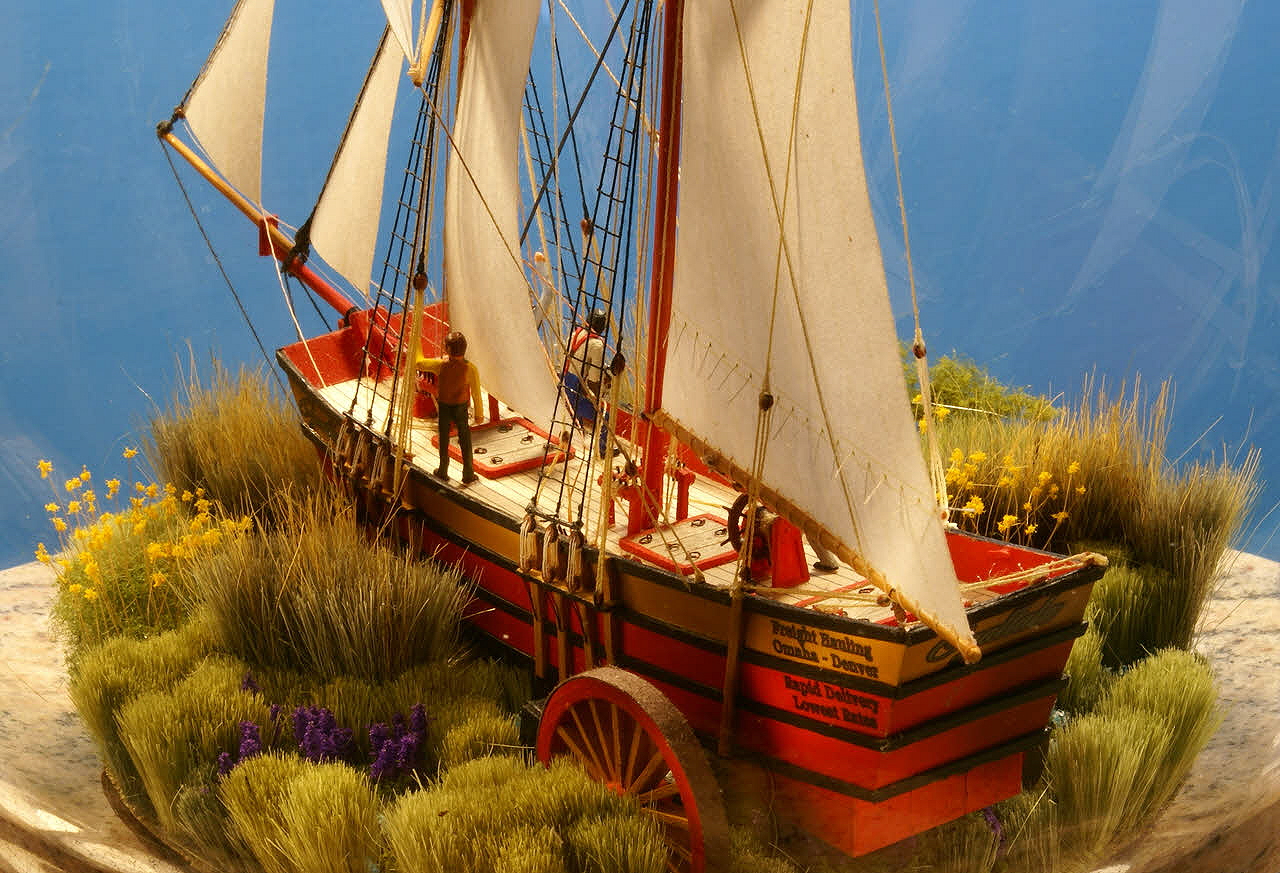
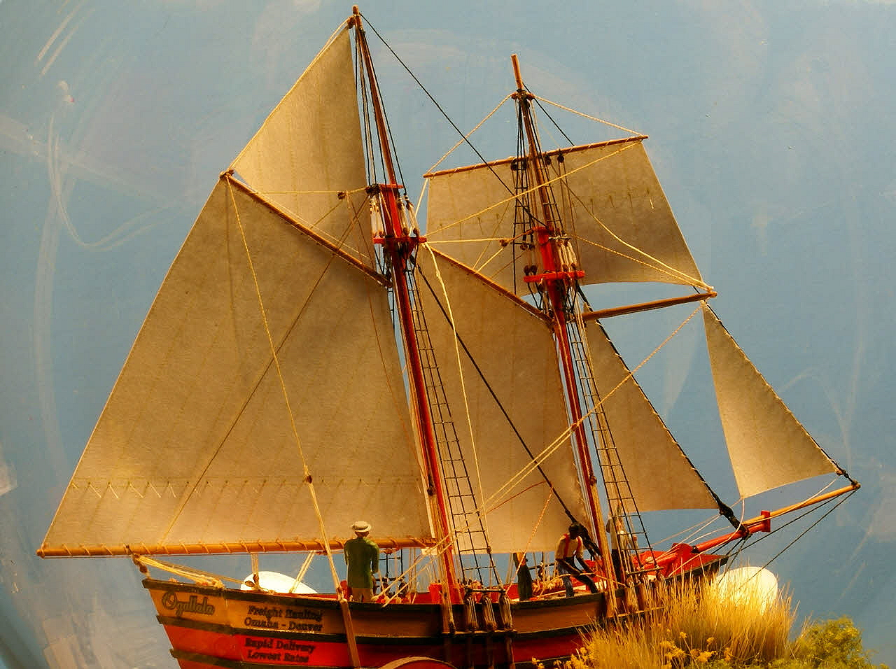
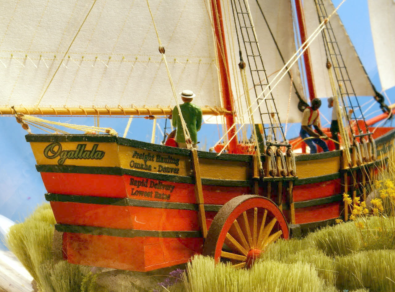
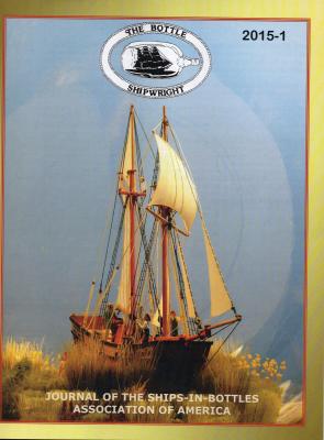
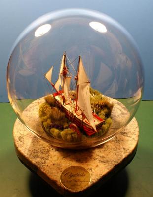
I'm posting a follow-up on Ogallala. Upon finishing her I submitted photos to Bottle Shipwright, the quarterly journal of the Ships in Bottles Association of America (of which I am a member), and quickly learned that Ogallala would be the featured SiB in the March issue which I received a few days ago. Here's the cover. I'm not going to bore you with posting the photos from the article because they have already been posted here. As an aside, I mentioned a couple times in this build log that I can't really see my work for what it is. All I can see are the deficiencies no matter how minor. Ogallala has been sitting in a box on a shelf since I finished her in late October - until today. I'm now able to see her as a whole and I'll admit I was impressed and very pleased. If you haven't seen them yet check out my two current projects listed in my signature.
- 170 replies
-
- 6
-
-
- ogallala
- praire schooner
- (and 2 more)
-
You should be able to save your Word document as a pdf then post it without a problem.
-
That's one way to rationalize my laziness. I'm very pleased to be back to work on Esmeralda and sharing my progress with my friends here. Thanks to all for the "welcome back". Dave
-
Welcome to resumption of work on Esmeralda. I haven't worked on it in over a year so picking up where I left off was a bit difficult. I decided I have some re-work to do to incorporate some techniques I learned or improved upon since the last work done. I also have a lazy streak. There are a large number of round port lights on most of the deck hatches that I didn't originally intend to reproduce but decided I can't leave off. I realized I could do them as decals on the eight hatches and prepared them on the computer and printed them on decal stock along with the yellow metal stern relief detail and name. Hatch cover details and stern relief decals. Before applying the decals to the tops of the white deck hatches. After applying the decals. The difference is more noticeable when you click the image. There are 146 port lights in the hatch covers. To do the stern detail I had to photo-shop the relief from a photo of it and adjust that image for the curvature of the stern to print it on a flat surface and for the distortion from the angle the photo was taken. I also had to do some color correction to make it look bright and shiny (the photo was taken on a dark, overcast day so the relief looked very dull). then reduce it for the model. Esmeralda's stern relief. I have to wait about 24 hours before coating all the decals with a couple coats of artist's matte varnish. The photo from which I extracted the stern relief. I realized while I was making the decals that this was the way I should have done the port lights on the hull. Live and learn. If I ever decide to do Esmeralda's sister ship Juan Sebastian de Elcano (a topsail schooner while E is a barquentine), any of the Gorch Fock sisters and clones (nine of them) or any ship with lots of port lights, I'll know what to do. Dave


- 84 replies
-
- 10
-
-
- bottle
- training ship
- (and 1 more)
-
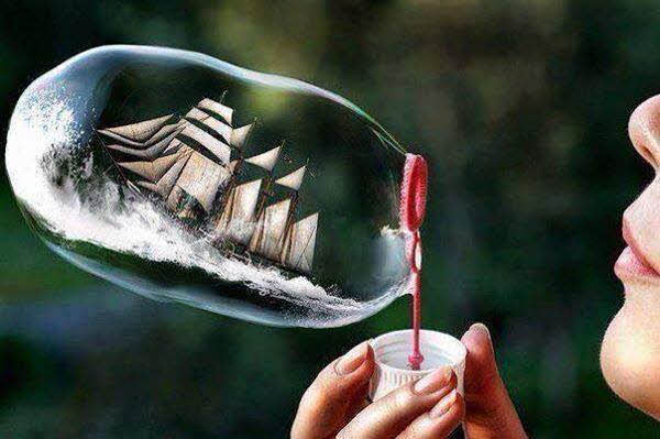
Finished Ogallala and can now get back to work on Esmeralda. I hadn't intended to take this much time away from Esmeralda but Ogallala turned into a much more comprehensive project than I had originally planned. I did find some more, useful, photos of E for some details on deck and aloft and kept her in mind during my side journey. I learned a few things from O that I will apply to E and I have a bit of re-work to do and some details to add before I pick up where I left off. I'll post my progress soon. I came across an interesting variation on a ship in a bottle with Esmeralda as the subject but the method is a bit too ephemeral for my taste. Dave
- 84 replies
-
- 8
-
-
- bottle
- training ship
- (and 1 more)
-
Jack Needham in his book "Modelling Ships in Bottles" has an entire chapter covering this subject and it's the best discussion of the interaction of wind, swells and ships I've seen. I highly recommend it. You can look at wave propagation theory but that's mostly calculus based and isn't much help except for some of the basics. As wind velocity increases so does the height, interval between crests and the speed of the swell. One aspect of wave theory that's interesting is how waves of different magnitudes and velocities interact and may be useful - the Wikipedia article on wave theory has several animated representations of the effect. A study of the Beaufort wind force scale is also very useful. Look at several graphic representations on the web, there are lots of them. Notice in the scale that there is only a narrow range of wind velocity that causes wind swells to break and roll over. Below but near that range, crests may get a bit frothy at random peaks, and above that range the crests get blown away as spray in the air and froth down the lee side of the crest. Many ship bottlers tend to make their waves look more like surf with lots of breaking waves rather than a series of swells as seen in open, deep-water seas, but you're not making that mistake. All in all, you seem to be on the right track. I like the effect you show on the lee side where the bow wave has combined with the swells to change their angle, it's spot on; other than a "bone in her teeth" nothing else is needed on that side. I'm aware that you haven't addressed bow waves and a wake but I suspect you have a good handle on them. There's also a wave that can propagate from the water that passes under the hull, rises to the surface (following the hull shape) and meets the water passing along the side. Where this occurs, it's magnitude and the angle of this small wave depends on the hull shape. Compared to a prop driven vessel, the wake will be relatively smooth with much less froth. I may be mistaken, but I seem to recall that you intend to depict Preussen under shortened sail in high wind. I suggest that you consider increasing the interval and magnitude of your swells and depict them with blown-away crests. The wind effects on the sea need to match the number and set of your sails. The way you have it now the wind is from the starboard quarter, but when the forward motion of the ship is added in, the apparent wind from the deck of the ship will be closer to being off the beam so keep that in mind when you brace the yards. I like your very methodical approach, it bodes well for a successful completion of this very ambitious project.
-
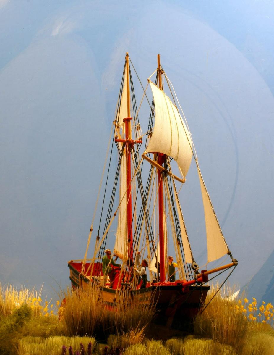
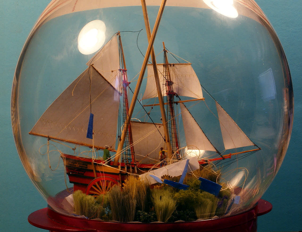
Thanks for the very kind comments. Here's the best of the photos of the finished Ogallala. Thank you to all who viewed this log and especially to those who contributed with 'likes' and with comments - you all pushed me to do my best possible work. Now I can get back to work on Esmeralda. I learned a few things here I can apply to "The White Lady". Dave


- 170 replies
-
- 11
-
-
- ogallala
- praire schooner
- (and 2 more)
-
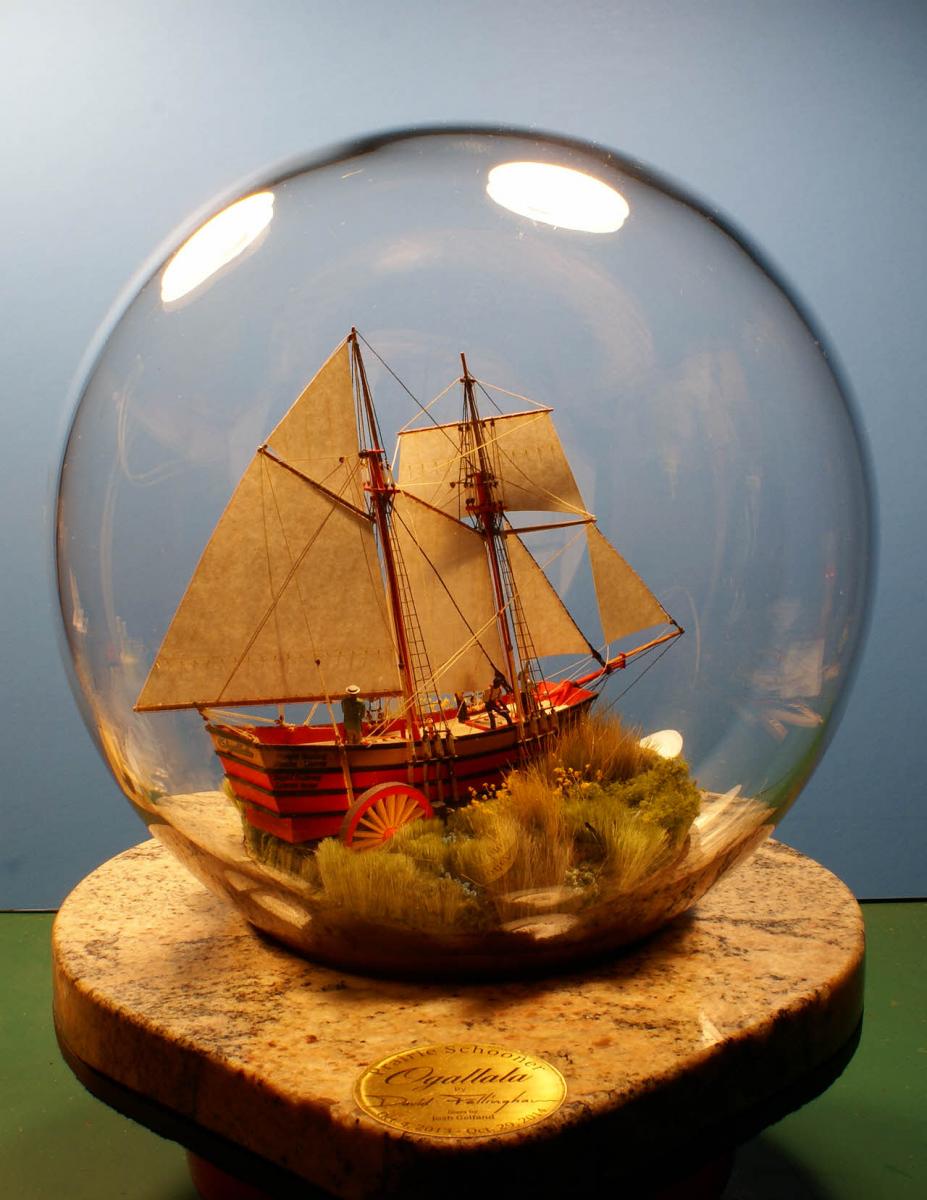
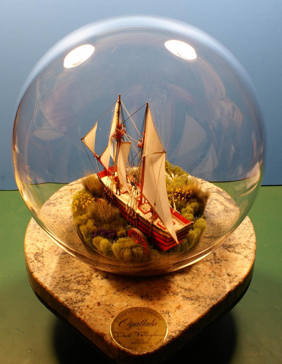
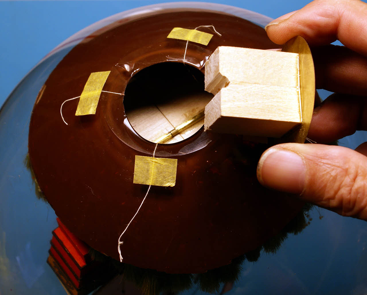
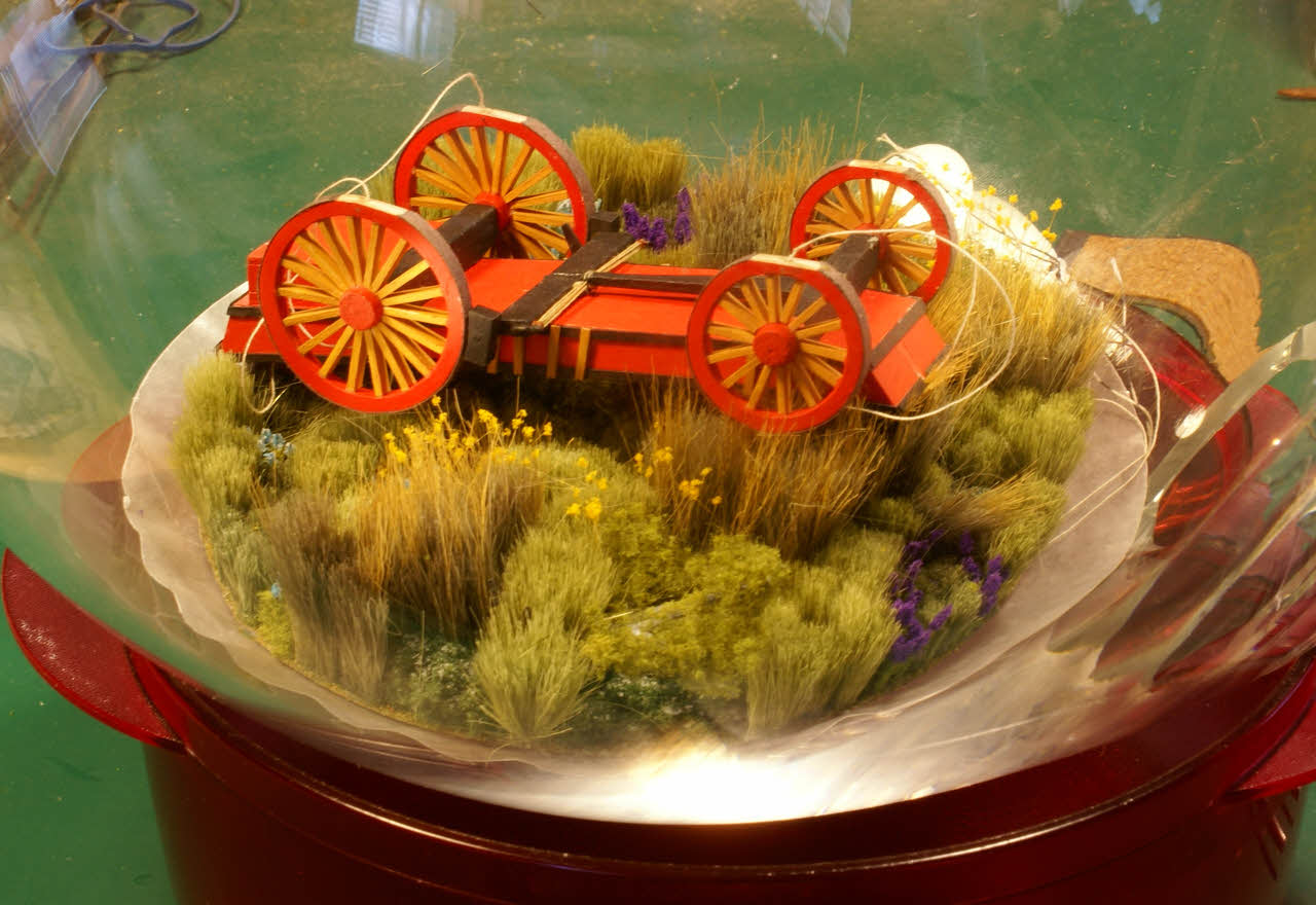
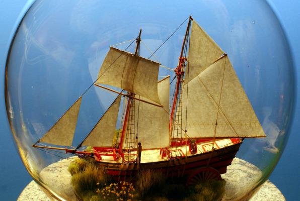
Ogallala is finished. Tensioned and secured all of the lines but had to redo one that was done wrong. Had to cut it loose at one end and glue another thread to it end to end, then re-tension the line, glue and trim it inside the bottle. Don't bother looking for the splice - you won't find it. Cleaned the inside glass again then located the prairie disc and ship using the four threads from the wheels taped to the outside of the opening. Once in position I epoxied the disc to the glass in three places. When the epoxy cured I painted the inside of the bottle below the soil line and re-checked the tension on the four threads. I had intended to simply epoxy the other medallion over the opening to trap the threads but decided this may not be secure enough. I cut a block of basswood to fit between the medallion and the bottom of the prairie disc and epoxied it to the medallion. When cured I epoxied that assembly to the disc and the opening. The medallion with the basswood spacer after checking the fit. I epoxied the assembly to the disc and the face of the opening to trap the lines as well. After the epoxy cured and the outside of the bottle / sphere was cleaned I took lots of photos. Here's two full view photos. I'm still going through them all and will post more tomorrow or the next day. Click on the photos for larger versions. Dave


- 170 replies
-
- 9
-
-
- ogallala
- praire schooner
- (and 2 more)
-
I laughed hard over that first sentence. I know how the wadded up mess looked (but it is a very apt description) and just wanted to clarify. Nothing about an SiB can be haphazard. I've tried many different ways to organize the threads that will be secured inside the bottle. Here, I prepared two strips of card stock, one for each side, with a series of slits cut along one edge to keep the lines organized with name tapes folded over the end of each line (in some cases pairs of lines). The lines are arranged from fore to aft along the card strip. The three major control lines (main, fore and jib stays) were the only black threads leading out of the bottle, so there was no chance of confusion there Dave.
- 170 replies
-
- 2
-
-
- ogallala
- praire schooner
- (and 2 more)
-
A lot of planning. Everything is planned towards the insertion in the bottle. I rarely mentioned the planning and various trial fits and the practice except in passing (because they're boring) but they were instrumental in the success and seeming ease of the assembly inside the bottle. The practice outside the bottle reduces the "pucker factor" during the insertion. I have noticed that few ship bottlers stop for a photo op during the insertion and I vowed to get a good photo at that point and others to show more of the process during this key phase. That "wadded up mess" was carefully laid down when I lowered the masts to make sure that the lines didn't tangle around items on deck like the four figures. It amazes me too when the erection of the masts goes as easy as this one did; it doesn't always work out that way. I hope so, at least enough to give a SiB a try. SiBs present different challenges than a conventional static model, but they also have several advantages. It occurred to me that I could build the entire US Navy of the War of 1812 in bottles and display them all in the same space that a larger scale Constitution would take. SiBs are entirely self-contained and transportable unlike a large Constitution in a display case. The miniature scales required present challenges as do the functionality of the model as it transforms during the insertion in the bottle and re-erection of the masts, but the personal gratification is higher than in a conventional static model, similar to building an R/C sailing ship. Some will enjoy the extra challenges and embrace them while others won't. I also hope to raise the perception of SiBs from "folk art" (with all the inaccuracies and disproportions implied by the name) to a respected method of building and displaying high quality miniature ship models. Even though Ogallala is pure fantasy, above the deck she is a very accurate model of a typical topsail schooner. If nothing else, I'm pleased that everyone who is following this project enjoys this voyage into the obscure art of bottling ship models. Unless something goes wrong, I anticipate one more progress report on this build log followed by lots of photos of the finished Ogallala. Dave
- 170 replies
-
- 5
-
-
- ogallala
- praire schooner
- (and 2 more)
-
You're right about that and it doesn't get better when in front of an audience. I compare bottling a ship model to launching a real ship - all the mechanical parts have to work right and together. And unlike conventional static models it can't be worked on again after the bottle is sealed.
- 170 replies
-
- 3
-
-
- ogallala
- praire schooner
- (and 2 more)
-
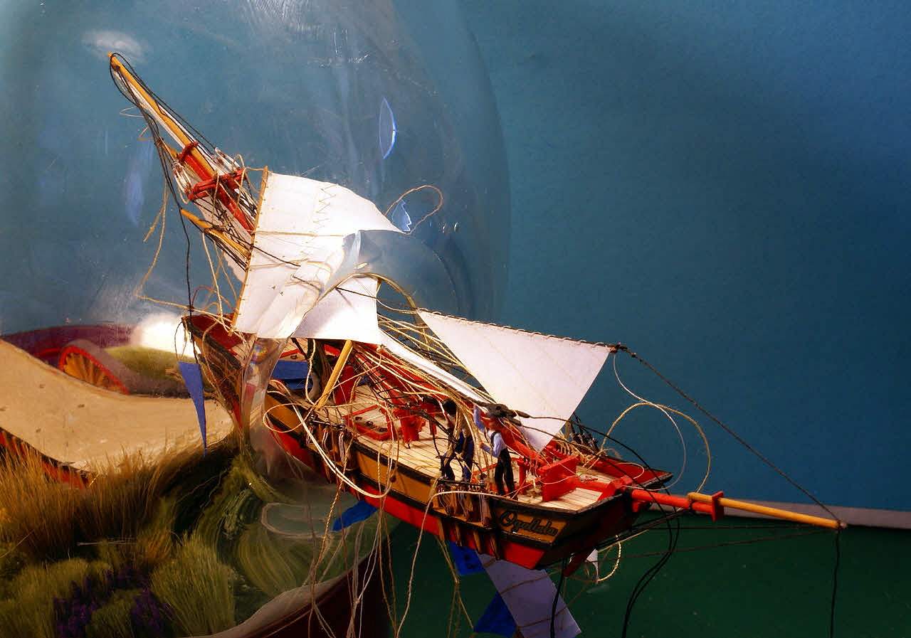
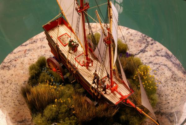
Thank you Keith and Omega and to all the 'likers', you're very kind. I started by wiping down the entire inside surface of the sphere to remove any debris from the base assembly. The rigging on many lines on the ship were slacked off, masts hinged down to the deck and the two big sails extended part way away from the ship and rolled to go in the bottle. The mainsail was rolled and started into the opening followed by the main masthead, fore masthead and then the transom of the hull. This was the tightest spot, then I had to adjust the fore topsail yard and crossjack as they slipped through. Part way in and looking good, no problems yet, even though the rigging looks like a rats nest again but it's more like organized chaos and will restore most of itself as the masts hinge back up. When I got the ship a little further in I started raising the masts and pulled the fore mast into its position, tied off the forestay at the bowsprit and glued it, then did the same with the jibstay. I turned the ship over, tensioned the mainstay and glued it where it comes through the bottom of the hull. Upside down, held in place so I can trim the two ends of the mainstay. Next step is to turn the ship back over and glue it to the lower hull. Upper hull turned over and glued to the lower hull. The crossed poles are bamboo skewers cut off about 1/8 inch / 3 mm out the opening with a lead weight on the ends while the pva cures. The three stays are the only lines that I've touched so far; more to go but the worst is over. From here all that's left is several tedious hours of adjusting about twenty more lines, then securing and trimming them. One thing about working inside a sphere I like a lot is that I can turn the model so the part of the ship I need to work on is near the opening - something I can't do inside the usual, cylindrical bottle. Dave


- 170 replies
-
- 7
-
-
- ogallala
- praire schooner
- (and 2 more)
-
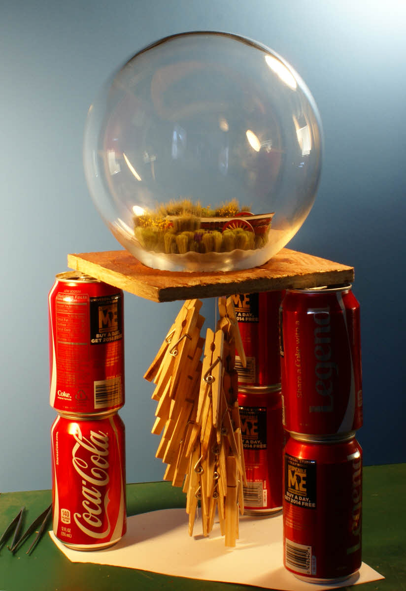
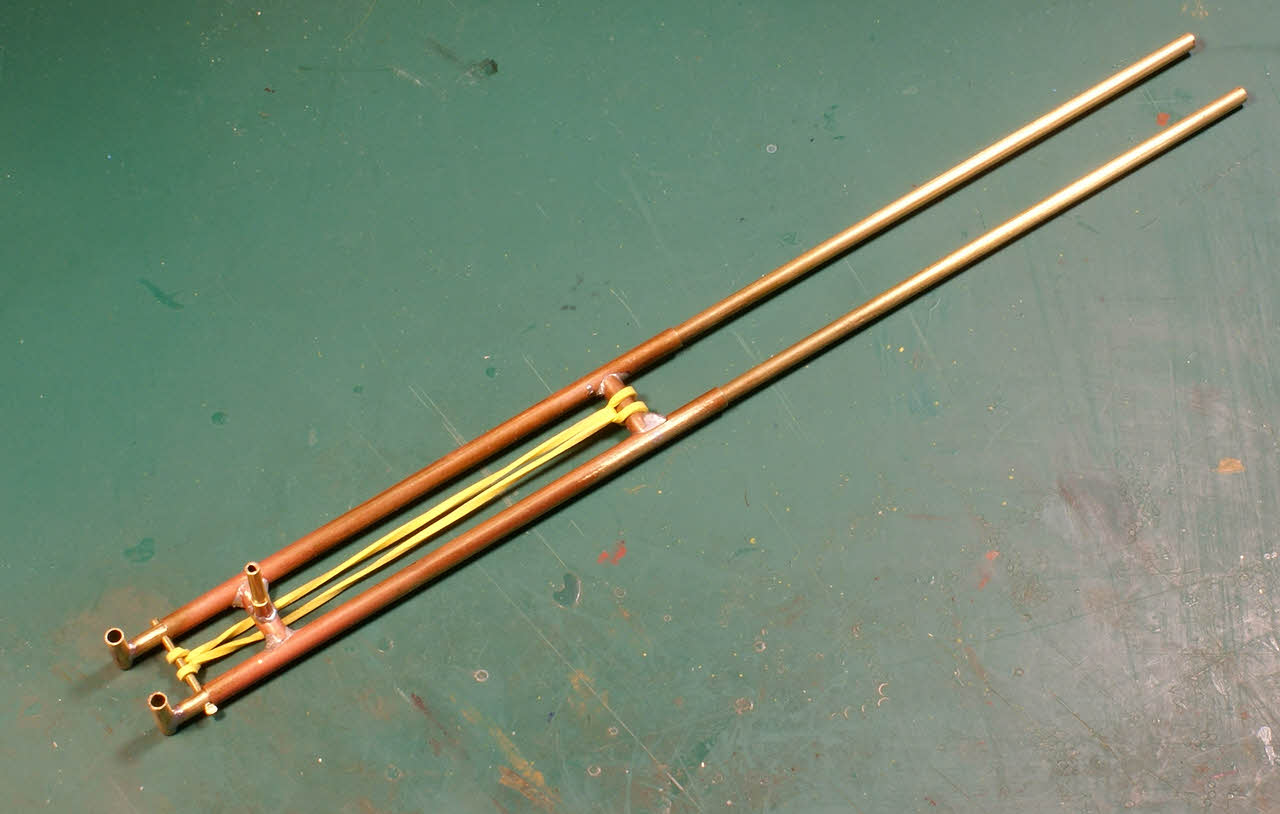
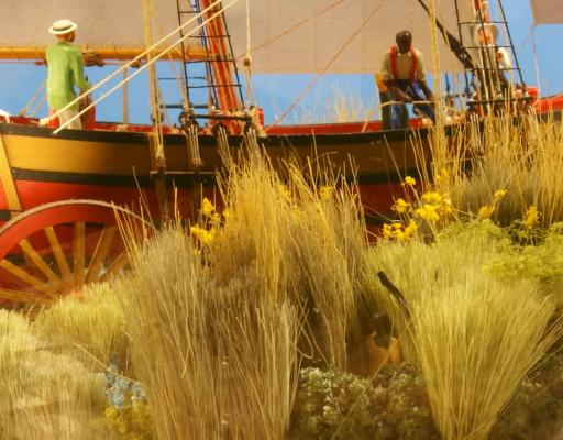
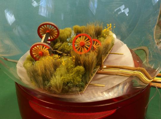
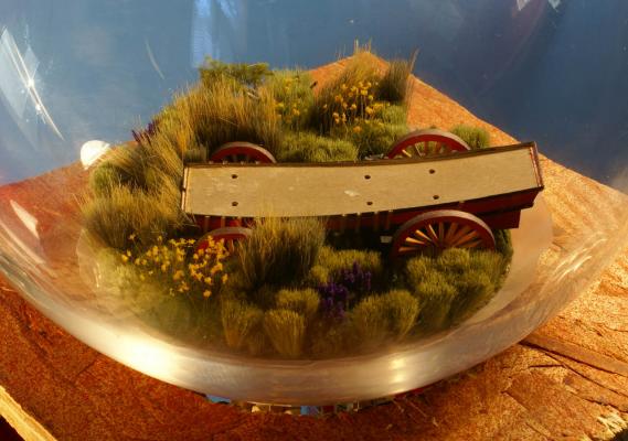
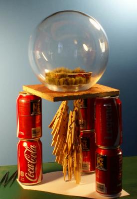
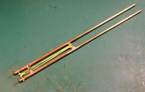
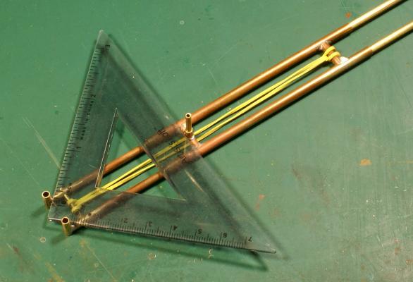
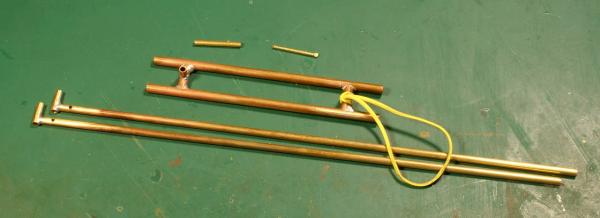
Don't hold your breathe you'll just pass out. I do enough holding my breathe for everyone just to help keep my hands steady. When working with the very small I can sometimes see my pulse transferred to the tip of a tool. I started by making and inserting a cone of waxed paper to protect the glass from smudges from painted surfaces, to protect those painted surfaces and to provide a catch for debris from the prairie segments. Using the clamping tool - I call it a trombone because of its resemblance to one - I assembled the prairie segments. This went so quickly and easily, relatively, that I almost forgot to take a photo. Three segments of prairie assembled with the wheeled assembles stationed for use a bit later. The trombone holds the segments together as the fourth is inserted, positioned and slid onto the three brass rods. The clamp is released from the three segments, opened to hold all four and then clamps them together. Using the trombone, the disc was turned over and the segments were glued with slightly diluted pva (about 20-25% water) painted onto the seams. This went very quickly - the photo was taken just 45 minutes after starting and the glue on the disc was drying another half hour later. I had to modify a brush by cutting it off at a slight angle just behind the ferule and gluing it back together rotated 180 degrees to give me a brush with a roughly 45 degree bend. Getting to this point took more work and fiddling inside the bottle. I used the trombone to hold the lower hull as the wheel assembles were glued to it. The threads kept getting in the way and I had to keep in mind that I had to turn this assembly over. I had to take it apart once to get the lines right. I used a model railroad scenery glue - Hob-e-Tac from Woodland Scenics - to assemble these three pieces. When spread on a joining surface and allowed to dry until clear (the glue is white) it acts like a contact adhesive. This glue isn't as aggressively tacky as contact cement and gave me time to get these pieces assembled. I used long tweezers and a pair of bamboo skewers, manipulated like chop sticks through the bottle opening, to get the wheels attached to the lower hull. This assembly took another hour and a half. The trombone was indispensable to both of these assemblies. It is rather simple and an improvement over one in my toolbox. The trombone clamp relaxed. The rubber band is the spring that provides clamping force and is easy to replace with shorter, longer or stronger bands when needed. The clamp holding a triangle to show how it works. The clamp disassembled. The small brass pin keeps the ends aligned. By making brass tube pieces to fit in the three vertical tubes the clamp can be easily modified to hold irregular objects. The small piece of tube with one end deformed so that it is a slight press fit in a larger tube is just an extender. The older version was essentially half of this with just one outer tube with a stop and an inner tube like one of these but it would not hold larger, irregular objects. Shrink tubing can be shrunk around the clamping points or the points can be wrapped with masking tape for finish protection. The next step was to glue the wheels of the lower hull to their places on the prairie. I slowly worked the wheels into the wheel tracks using the threads from the wheels and a tool to apply downward pressure from above. When the wheels were near their position I moved the waxed paper and disc until the bottle opening was on top and the paper and disc were on the bottom. I applied large blobs of pva at the wheel attachment points, allowed the waxed paper and prairie disc to slide over the opening as I slowly turned over the sphere, routed the threads from the wheels through the opening and pulled on those threads until the wheels were well embedded in the glue. Much of this latter work was done on an impromptu stand to allow access inside the sphere from below. I then attached clothes pins to the four threads to provide weight to hold the wheels in place while the pva cured. The impromptu stand made from soda cans, a piece of wood with a hole in the center and a piece of card stock all glued together. I need to make a more permanent version. Lots of clothes pins were used to weigh down the wheels into their places. Seven components assembled inside the bottle / sphere. Look familiar? This part took about two hours. I left the weights in place over night and all the next day before moving on to the ship itself. It took about five hours total, all in one day, to get these components assembled not counting breaks for photos, food, glue setting and my nicotine addiction. The clamp allowed the work to progress rapidly - combined with sufficient assembly practice outside the bottle to find and eliminate potential problems. Now for the last component. Dave


- 170 replies
-
- 9
-
-
- ogallala
- praire schooner
- (and 2 more)
-
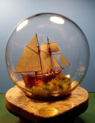
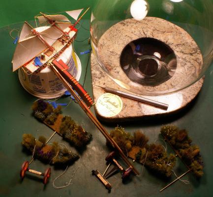
I have gone over all the components, touching up paint and completing final touches, and there's nothing for it but to stuff this thing in its bottle. One last photo of the eight components to be assembled inside the sphere while still outside. From lower left across: four prairie segments and the front and rear wheel assemblies. The wheels each have a thread leading through holes in the prairie segments to help locate them in their places. The lower hull is near center held with a clamping tool I made for this project - more on that when in use. The upper hull with rigging is at the upper left. At upper right is the sphere on its stone display base. I had it made by a local stone counter-top installer from a remnant from one of his jobs. It is mostly light tan with streaks of red and black through it picking up and complimenting Ogallala's colors. The base has the finished medallion permanently attached and an X-Acto knife for size reference. Click the image. I finished the medallions with a chemical blackening agent, sanded them until only the lettering remained black then sprayed them with clear lacquer. I'll post more on the base later. I cleared off my work area for the group photo and made sure (again!) that everything is ready. No excuses left. Dave

- 170 replies
-
- 7
-
-
- ogallala
- praire schooner
- (and 2 more)
-
Thanks Jeff, but the Micro-Mark Pro-Etch directions are very good and complete even though the process is somewhat involved.