jre8655
-
Posts
154 -
Joined
-
Last visited
Content Type
Profiles
Forums
Gallery
Events
Everything posted by jre8655
-
Popeye, I wish I'd seen this build when you started it. I purchased the Thermopylae kit quite some time ago and when I found that the instructions were in Italian I contacted the manufacturer and was sent an English version of the build sequence. I've attached them for you. Jack Thermopylae Assembly Instructions.doc
- 452 replies
-
- 6
-

-
- thermopylae
- sergal
- (and 1 more)
-
Tom, I'm not so sure I would try using the drill press/x-y table to cut out the bulkheads. Here's why: it's very easy to turn the adjustment knob the wrong way, thereby risking cutting in a direction you don't want to go. Now there is another way to do this...use the x-y table to move the cutting tool to a precise location then drill a hole. Repeat this all the way around the section you want to cut out, drilling a series of holes then just cut between the holes to remove the section. It wouldn't be much of a chore to file and sand the bulkhead after that. I've done this with some difficult pieces in the past and had very nice results.
-
Tom, I'm not sure if a Coping Saw is route to go. The spiral blades are hard to control and as mentioned are very course. The Jewelers Saw Blades are somewhat expensive and I have found Scroll Saw Blades that are finer. Several suggestions: Try using automotive masking tape on the back side of the plywood. It has a very fine grained adhesive and should not harm the wood. I've used scroll saw blades from Woodcraft that are up to 46 tpi and found they cut very cleanly with a minimal splintering on the back. Here is the URL: http://www.woodcraft.com/category/PA115-08-01/scroll-saw-blades.aspx?gclid=CKqOz5GY9coCFQoNaQodwj4PiA And one question. What kind (brand) of a Scroll Saw are you using?
-
I like it! I can't tell you how much time I spent tying knots on Ratlines and these were on 1:100, or less, scale. At those scales the knots look too large. I will have to try this.
-
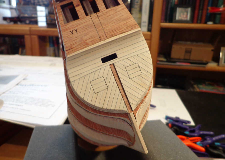
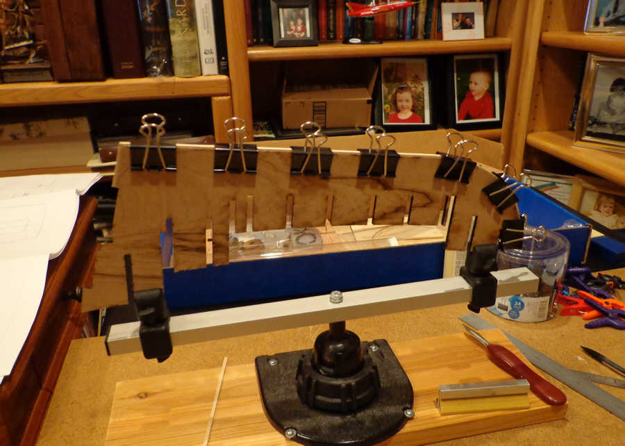
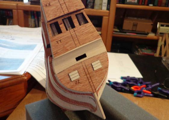
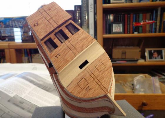
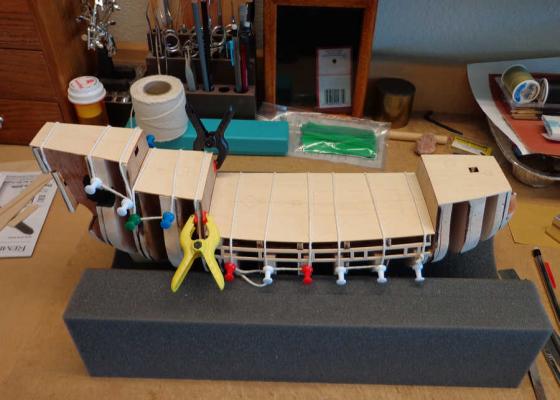
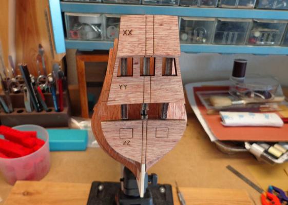
I used the first set of planks that I prepped with the plank jig for the stern and counter. The instructions called for a layer of 1/16” x 1/8” planks to be applied to the counter. When I finished this set of planks I noted that there was a 1/16” drop from the stern piece ZZ to the counter. I found that I had to apply a second layer of 1/16” x 1/8” planks in order to achieve a smooth transition from stern piece ZZ into the counter. I’m thinking that maybe the planks should have been laid flat instead of upright; however, the plans show them laid upright. Once these two layers of planks were sanded to shape and blended together I began the second layer of 1/32” x 1/8” planks. Per the instructions, the gun port lids are placed first. With the gun port lids in place I transferred the angle of the planks from the plan sheet to an adjustable protractor (37°). The planks were then cut and applied to the stern piece ZZ and finally to the counter. < I realize that most of the stern planks will be covered with white paint so all this lovely caulking will be lost. I therefore considered this an opportunity for me to practice coloring the plank edges and laying the planks in preparation for the deck planking job that lies ahead.

-
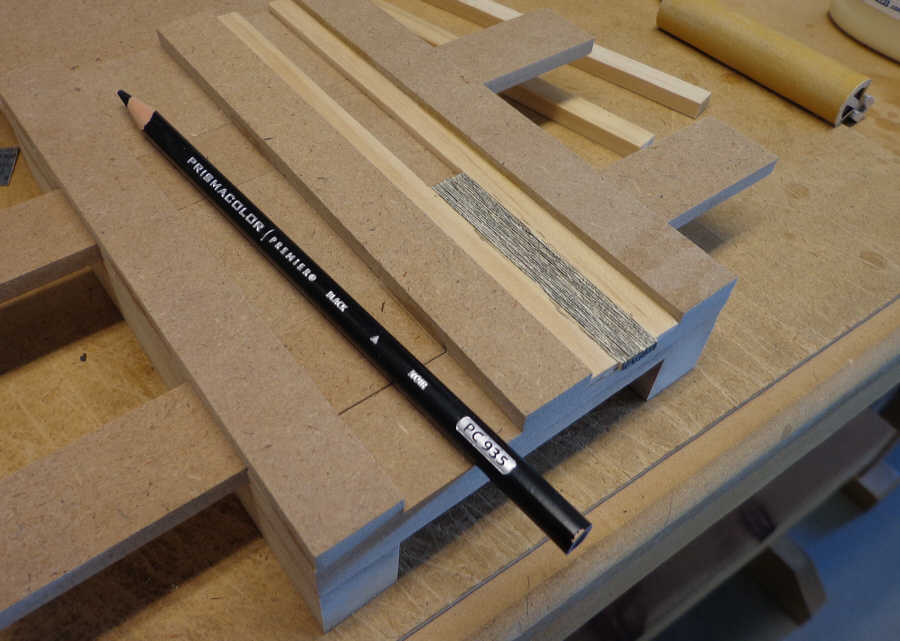
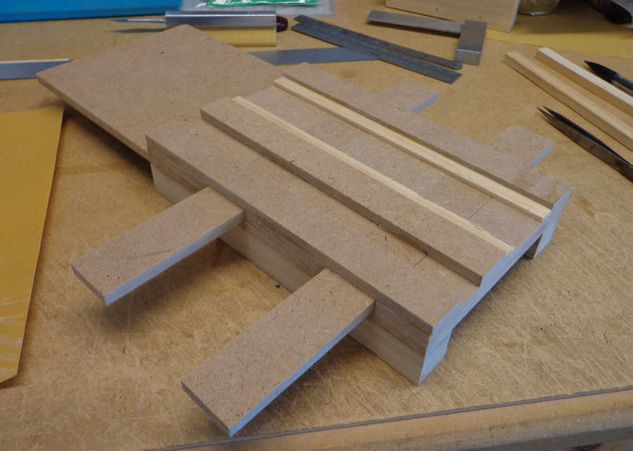
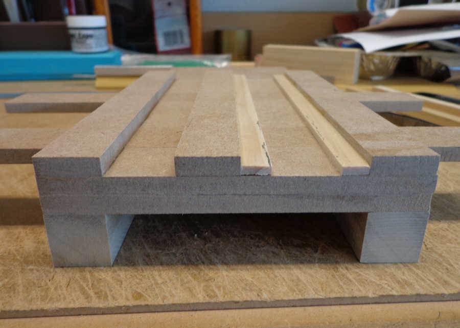
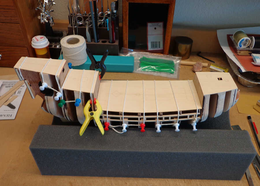
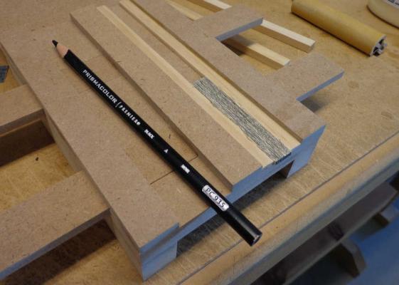
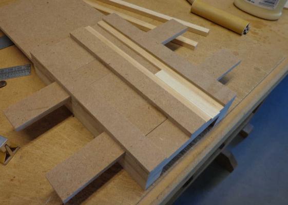
Previously I made a comment that I was going to construct a jig to help prepare planks for this build. I wasn’t sure if the time spent designing and building such a jig would ultimately save future effort with the planks. Well here is the jig I came up with. The center section of the jig is movable slides to clamp the planks between the two pieces of pine. These pieces were cut to a 3/32” thickness to accommodate 1/8” wide planks. This would allow for sanding the planks to the same thickness. I spent one morning at our community woodshop and cut all the pieces from ¼” Masonite. The two lighter colored pieces are pine. The idea was to have a clamp that would hold a number of planks so they could be gang sanded to the same width and length then edge colored to simulate the caulking. To test the jig I cut 25, 1/32” x 1/8” planks and stacked them in my jig then closed it. There is enough friction between the pieces of Masonite to hold the plank stack, but if needed I can wrap a rubber band around the slides to add pressure. Once in place it was a very quick operation to sand all the planks to the same dimensions. After sanding, I colored the edges with a Prismacolor black pencil. Now it’s on to applying the planks to the model.


-
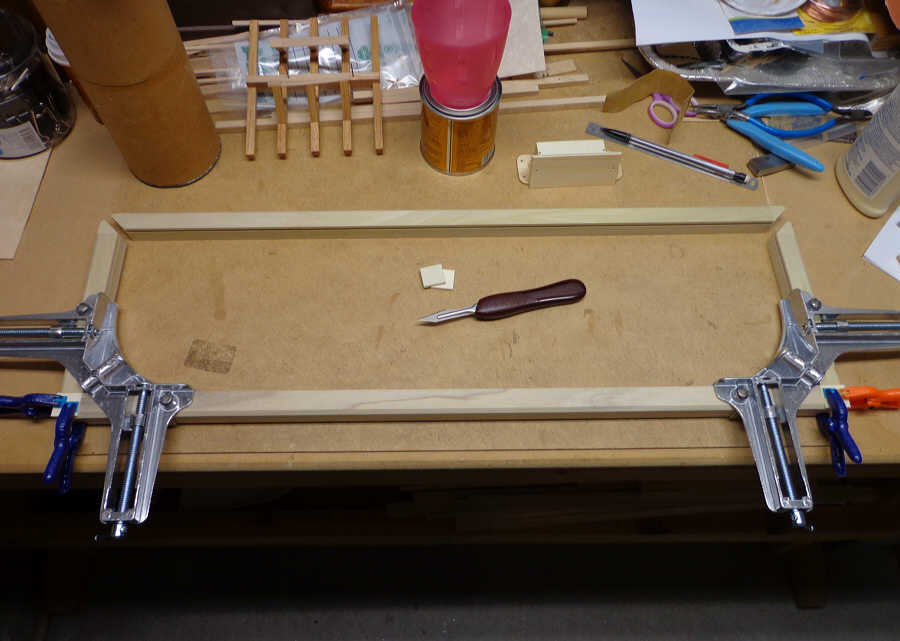
Thank you Frank. I've set about trying to construct a jig that would help with trimming and prepping the deck planking.
-
Thank you Nils. I hope to do the forum proud.
-
Ah ha! So at this scale a 20 ft deck plank would be 3 inches in length. That explains why the Forecastle, Half Deck, and Poop Deck all have deck planks running their entire length. Thanks Russ. I very much appreciate the help.
-
All the decks are now glued in place and the upper sections of the bulkheads and decks are faired. I’ve been reading over the instruction manual and delving into some of the other Mayflower build logs for information on planking the decks. Looking at the plans and the photos in the manual it looks as though the deck planks are laid down in very long sections. I’m not sure what length these planks should be, but I’m thinking of making them about 1.5 to 2 inches in length. There is an illustration in the manual showing the deck planks much shorter than depicted in the photos. Any thoughts on this?

-
How to build a wood case ?
jre8655 replied to alexmd's topic in Painting, finishing and weathering products and techniques
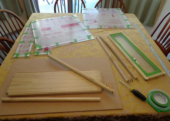
All the 1/8" grooves, base and frame pieces, were cut with the MicroLux Table Saw. I used a Dado disk with the blade for the 1/8" cut. The Lexan acrylic was cut to order when I purchased it. I had the dimensions figured out when I got it. -
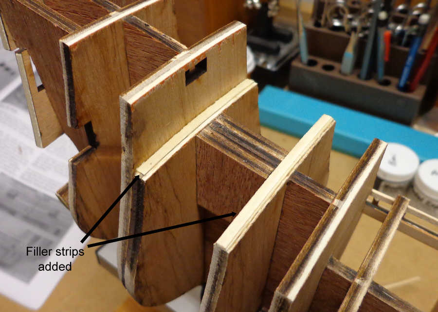
Once I began fairing the bulkheads I realized that there were several places where it would be necessary to add some filler material to achieve a nice roundness to all the bulkheads. I decided to add filler blocks to most of the bulkheads to get the roundness I wanted and provide a wider gluing surface for the planking. I used some scrap balsa for the fillers. I have a fair amount of experience with balsa from my days building model airplanes. Now it’s time to get on with the planking.
-
How to build a wood case ?
jre8655 replied to alexmd's topic in Painting, finishing and weathering products and techniques
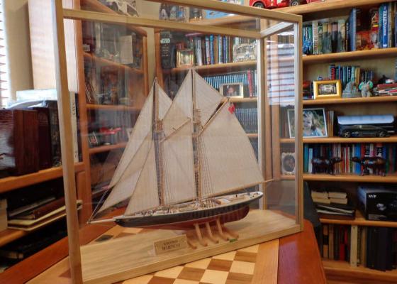
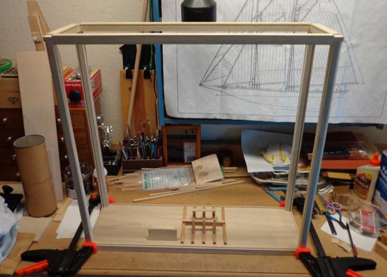
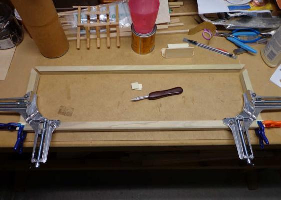
Using the dimensions you posted, your case should be about the same size as the one I made for my Bluenose. I made that case using Poplar. The base is 24" x 7.5" x 3/4". All the pieces for the frame are of 3/4" square Poplar. The case is 23" high. Here are some photos of the case construction: All the acrylic is Lexan and the pieces slide into 1/8" grooves I cut using a MicroLux miniature table saw. The wood frame certainly provides strength and you don't have to worry about trying glue the acrylic itself. I believe that at some point you will have to use a table saw to cut the parts. If you know someone that has one, you could ask to use it for the amount of time it would take to cut and groove all the parts.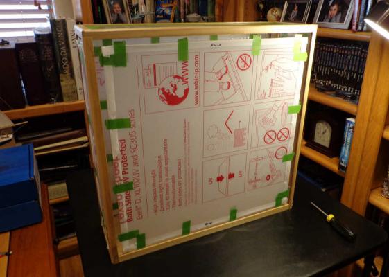
-
How to build a wood case ?
jre8655 replied to alexmd's topic in Painting, finishing and weathering products and techniques
Realistically, the only way to cut a groove in the wood is with a table saw. You can set up the rip fence on the saw to cut the groove whatever distance you want from the edge and adjust the saw blade to the depth you want the groove. Once the rip fence is set up, say to allow a 1/8" space from the edge of the piece to the groove, you can then cut the groove in all the pieces. -
Many years ago, around 1973, I purchased a Unimat SL. That thing was a variable (belt driven) combination lathe (metal and wood), drill press, verticle milling, table saw, jig saw, disc sander, flexible shaft handpiece, all around whatever you needed machine. There were so many accessories available that it was an entire workshop rolled up in one. Wish I still had it!
-
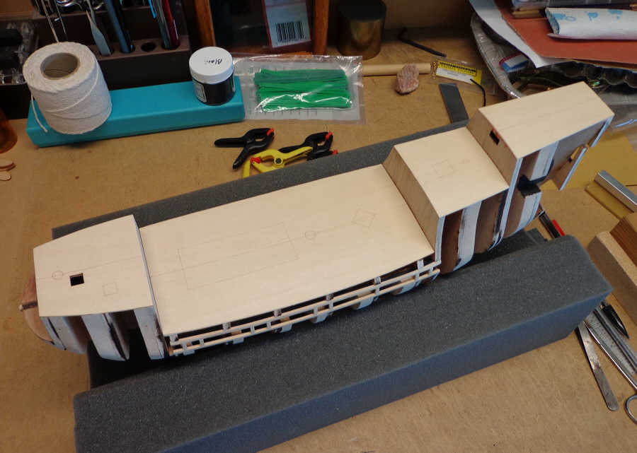
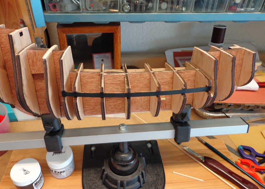
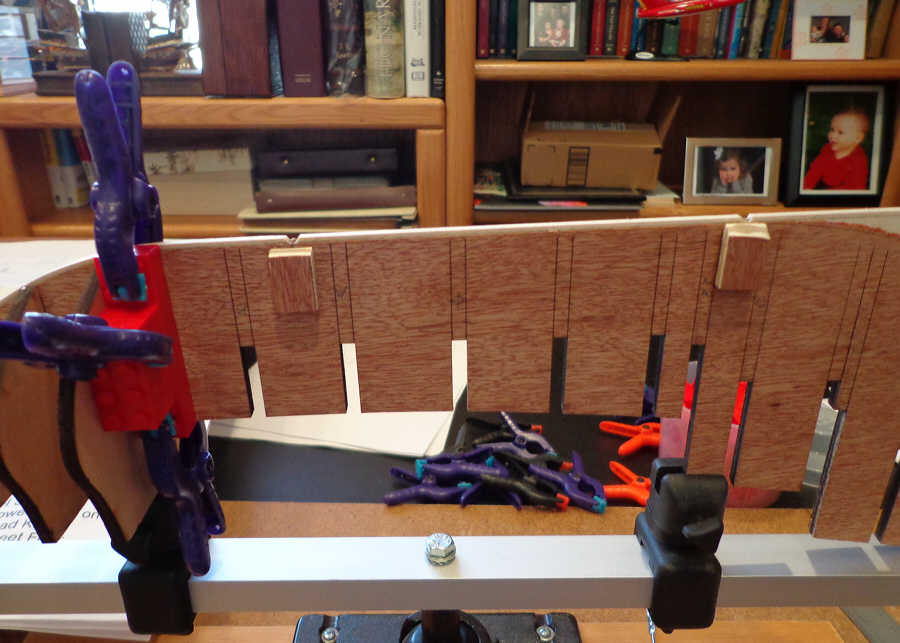
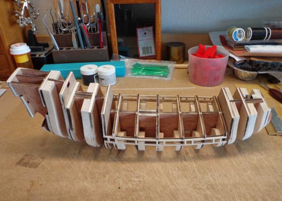
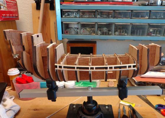
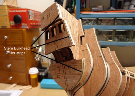
Moving on with the assembly process, the gun ports are in place. There is a Dummy Cannon Support Strip glued into the recess in bulkheads spanning the center of the ship. This strip is painted black to hide the interior of the model. I really haven’t decided if I want to build the model with open gun ports or not. Either way, when the time comes I have it ready. The next order of business is the construction of the gun ports themselves. These are made up from 3/32” square strip. I made a copy of the section of the plans to use as a template for locating the gun port positions of each side of the model. Additionally, I made a small jig to make sure that all the gun ports are the same size. It is now time to start fairing the bulkheads. As I began this I noticed that there is some difference in the bulkheads that needed to be corrected. I added 1/32” thick strips to the bulkheads to give me a truer curve to the top of the bulkheads where the deck will be glued. I also added some additional material to the stern bulkheads to make a smoother curve without having to reduce the bulkheads unnecessarily. There may be some other areas that will require filler strips. As I fair the bulkheads I’ll add these as needed.


-
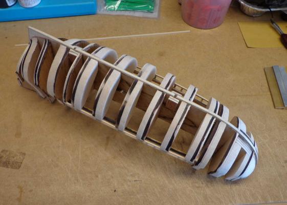
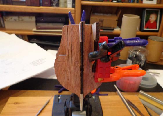
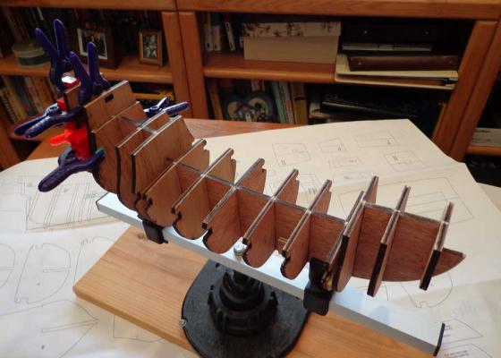
Russ - I sent a message to Chuck and received a reply. There will be holes through the deck and into the filler blocks. He says it's not neccessary to drill these holes now and to wait until I'm ready to set the masts. Thanks for your suggestion. Now on to the build. The weekend was very productive. The stern frames were added. When I test fit the 3 stern bulkheads, XX, YY, and ZZ; I found that the ZZ Bulkhead only had support in the center from the keel. I was afraid that when it came time to fair in the bulkheads it wouldn’t be enough support and this bulkhead may just break off. I added 2 extensions to the frames for additional support. Now everything is square and secure enough to withstand the fairing process.
-
Jeff - sorry to hear about your problem with the plywood for the keel. I did notice that there were several areas where the plywood is missing strips in the middle ply on this kit. I'm thankful that it's not in any critical area. Russ - I went back over the plans and instruction maual as you suggested. Maybe I'm looking for something that isn't there. I see where each mast has a Tenon shaped into there base, but I can't find any mention of cutting a Mortise in the decks. I re-read the section on stepping the masts on page 36. It appears that the masts are set into a ring (mast coat) then glued to the deck. Sorry if I'm dense, but I just thought there would be some sort of "hole" drilled into those filler blocks. Anyway, the build is coming along and I was able to make progress this weekend. Will post as soon as I can.
-
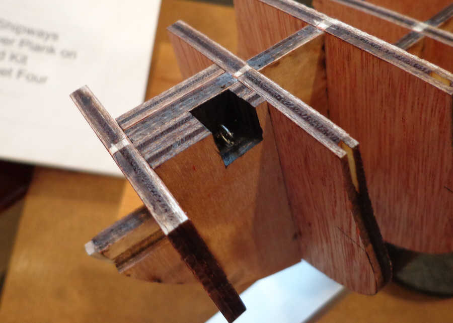
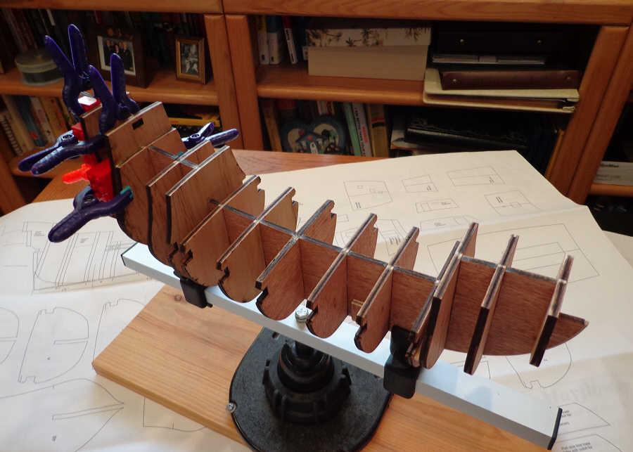
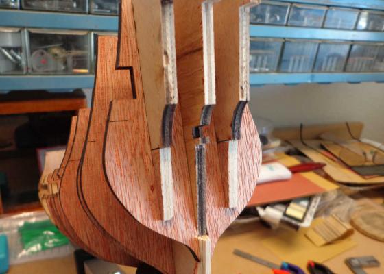
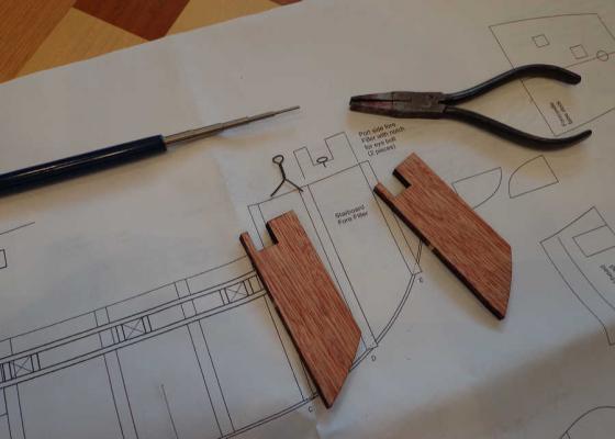
With all the bulkheads in place it’s time to start adding the filler blocks. Everything is pretty straight forward with the exception of the Fore Filler Block. This bit of construction consists of 3 blocks: 1 on the starboard side and 2 on the port side. The 2 port side blocks have a notch cut into the top. An Eyebolt has to be fabricated and glued into this notch. The instructions call for the blocks to be glued together and then glued between bulkheads D and E. Then a hole drilled into the notch at the glue joint. I made the eyebolt, using the 28 gauge wire provided, but cut a slot in each of the filler blocks where the eyebolt was to be placed. When the filler blocks were glued in place it was a much simpler task to glue the eyebolt in place since the hole was already there. The placement of the eyebolt is somewhat confusing because the plans show it facing port/starboard. The instructions indicate the eyebolt is to face fore/aft. Be careful with this placement. The plans are drawn to show the size of the eyebolt, not its proper alignment. This eyebolt is shown on plan sheet two and described on page 47 of the instructions as being an anchor point for the Fore Tie and Ram’s Head Block for the Fore Mast. There is still one more thing about these filler blocks that bothers me. There are no slots or holes in the keel, nor are there any indications or instructions to drill holes for the masts. I haven’t, as yet, anything in the instruction manual either about drilling holes for the masts. Anyone have a clue on this?

-
Dave, Nice to hear from you. The amount that needed to be removed was very minimal. I used a small flat file to take off just enough to allow a smooth fit. There was some play still left between the parts so they could be squared up. As far as the weather goes...I don't think we should say anything. The rest of the country will hate us. Actually, if they're watching the nationwide weather reports they hate us already. The keel clamp is great! I purchased it from Model Expo when I set about building the Bluenose. I like the freedom the piviot provides. Just rotate the arm until you get to where you need to work.
-
Thank you Russ. I made considerable progress these past two days. I'm sure it will slow down very soon as I get past the large pieces and on to the little ones.
-
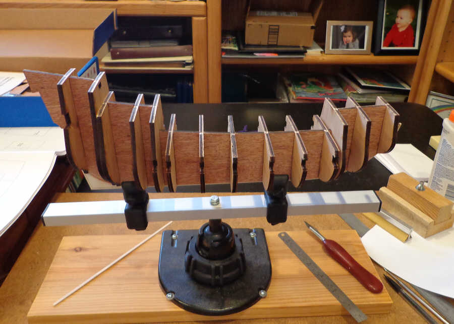
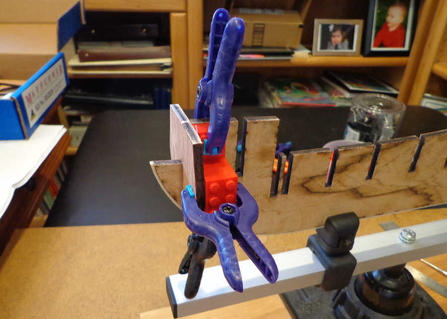
I cut loose all the bulkheads and test fitted them to the keel. With two minor exceptions the bulkheads all fit very nicely. Two of them required minimal filing to trim out the slots. With everything lining up nicely and the keel is straight it’s time to start gluing. Thanks to those who posted build logs I followed their wisdom and invested in a container of Legos. Those babies sure come in handy! One of the things I did before beginning any of the actual construction was to read through the instruction manual. I didn’t find anything about when, or where, to install the pedestals that come with the kit. I realize that at some time in the future I will have to drill into the keel to mount the ship on these pedestals. I figured that I had better plan ahead and marked the locations for the pedestal screws. I marked these locations on both the keel and the plans. At this stage of the build I made four reinforcement blocks and glued them to the keel in the locations I marked. I tried to drill a hold in a piece of the scrap the keel came out of and found it almost impossible to drill a straight hole without the bit drifting out one side or the other. That’s why I thought it a good idea to reinforce and drill these locations now. Legos in hand, clamps at the ready, it was time to start gluing. This was actually fun! The way all the bulkheads fit the gluing went fairly fast.


-
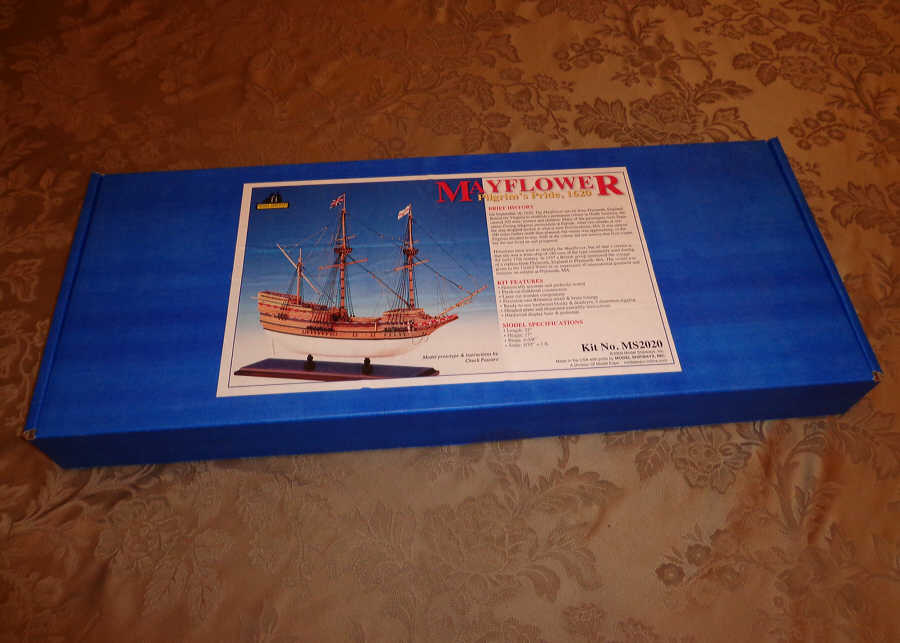
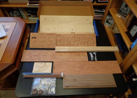
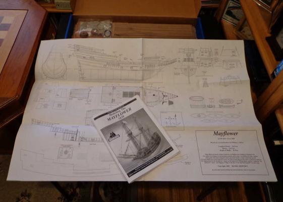
This will be my second build. I completed the Schooner Bluenose (scale 1:100) and set about deciding which ship to build next. Thanks to the Admiral, I have several kits to choose from. These were purchased over a two and a half year period following my decision to retire…for good. The Admiral asked me what I wanted to do in retirement and I said build model ships. I made a list and when the kits came on sale I would purchase them. I now have nine from which to choose. I rolled the bones and read the signs. The spirits told me to build the Mayflower next. Actually, I looked at them in chronological order. The Mayflower would be first because it was built, date wise, before any of the others for which I have kits. Since the Bluenose was a Model Shipways Kit and seemed to be very well designed, had a good set of instructions, and very good material I look forward to building the Model Shipways Mayflower based on the experience I had with the Bluenose. I also sought out the build logs that are posted on the forum for this same kit. Opening and inventorying the kit was not all that time consuming. The parts list gives a very good description of each piece and the way the kit is packaged makes it a snap to find everything. The four sheets of plans are large (I can see them without my glasses) and quite detailed. I spent about an hour reading through the instruction manual and surprised at how well the construction is broken down and described. Step one was to cut loose the keel. It came right out and is straight and warp free. The keel has a Bearding Line etched on the starboard side at the stern. Using a French Curve I marked and transferred that line to the port side. There is a Rabbet Strip that needs to be glued to the bottom of the keel from the stern all the way forward and up the bow. I soaked this strip for about half an hour and clamped it in place to dry. Once this is glued the keel is tapered, along with the Rabbet Strip, to a thickness of 3/32”. I hope to get all this done before our two year old grandson finds me. All observations, criticism, advice, and comments are welcome and encouraged. I sure don’t consider myself any sort of expert after just one build. So here’s hoping that everything works according to plan…and instructions!


-
Adam, I was reading through the manual this morning as I was getting the parts inventoried and found the section that refers to that eyebolt. On page 47, under "Fore Yard..." it's explained as being a substitue for a knight that is supposed to be located below the forecastle deck. The eyebolt is used to secure the ramshead. I'm still on page 2, paragraph 1, in my construction phase.
-
Airbrush results in "fuzz"
jre8655 replied to jmorgan11's topic in Painting, finishing and weathering products and techniques
Jesse, I've been using the Model Expo Paints and Primer. It's been working very well for me. They're an acrylic based paint that is easily thinned with water. Clean up is very easy.