


Glenn-UK
-
Posts
2,630 -
Joined
-
Last visited
Content Type
Profiles
Forums
Gallery
Events
Posts posted by Glenn-UK
-
-
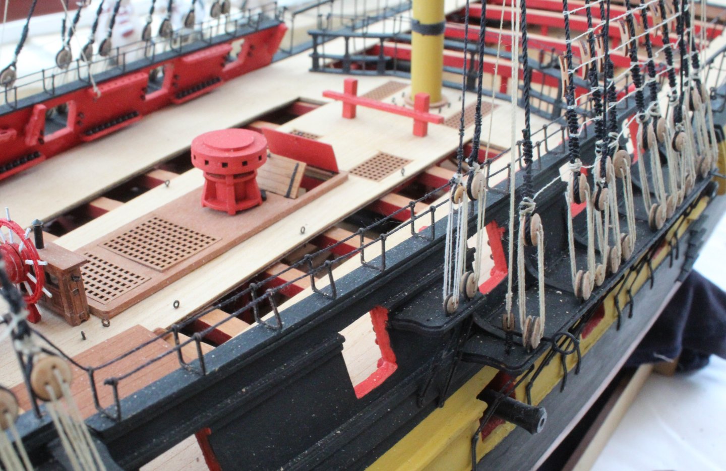
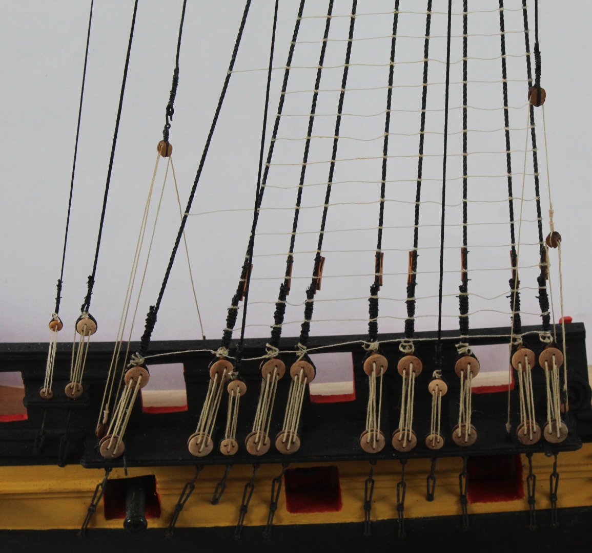
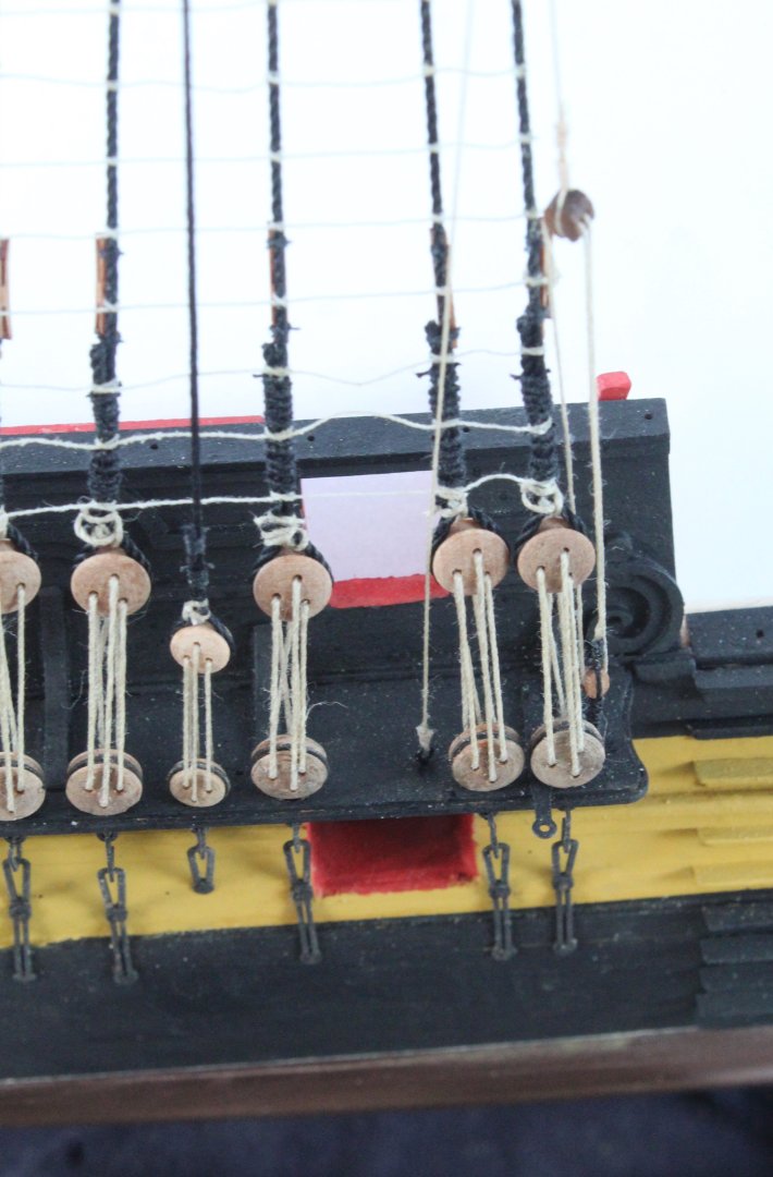
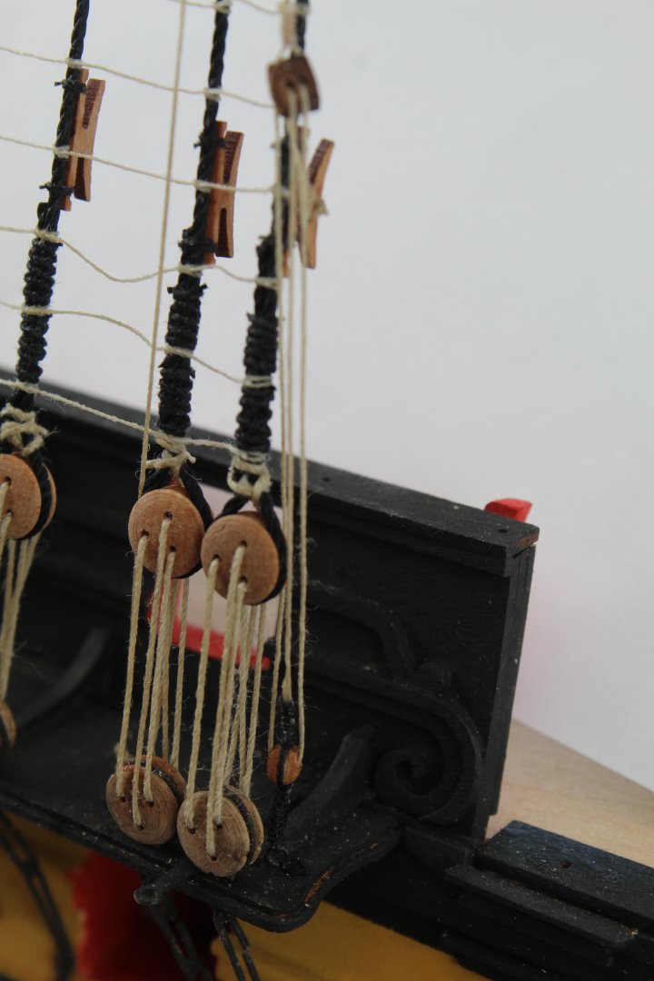
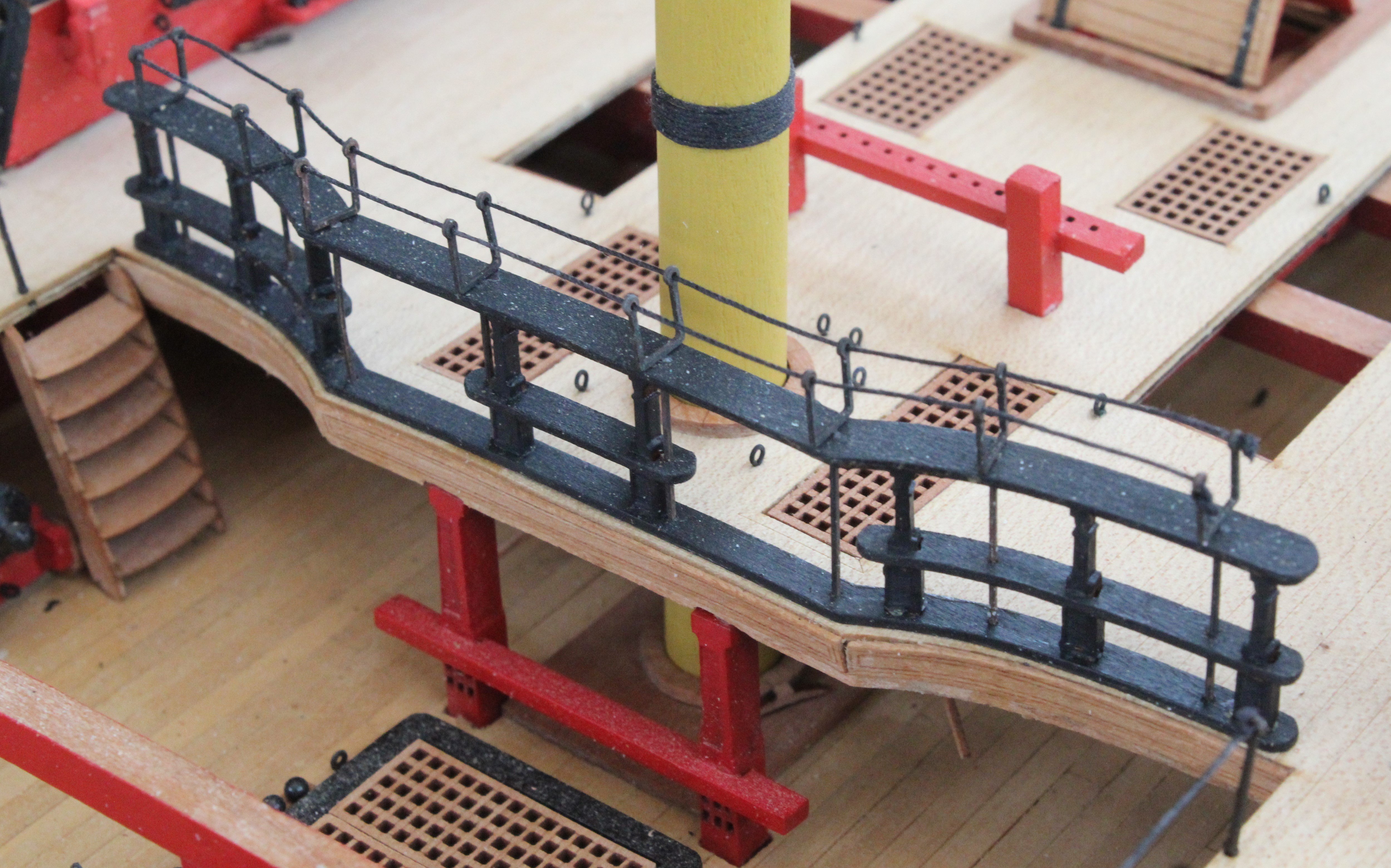
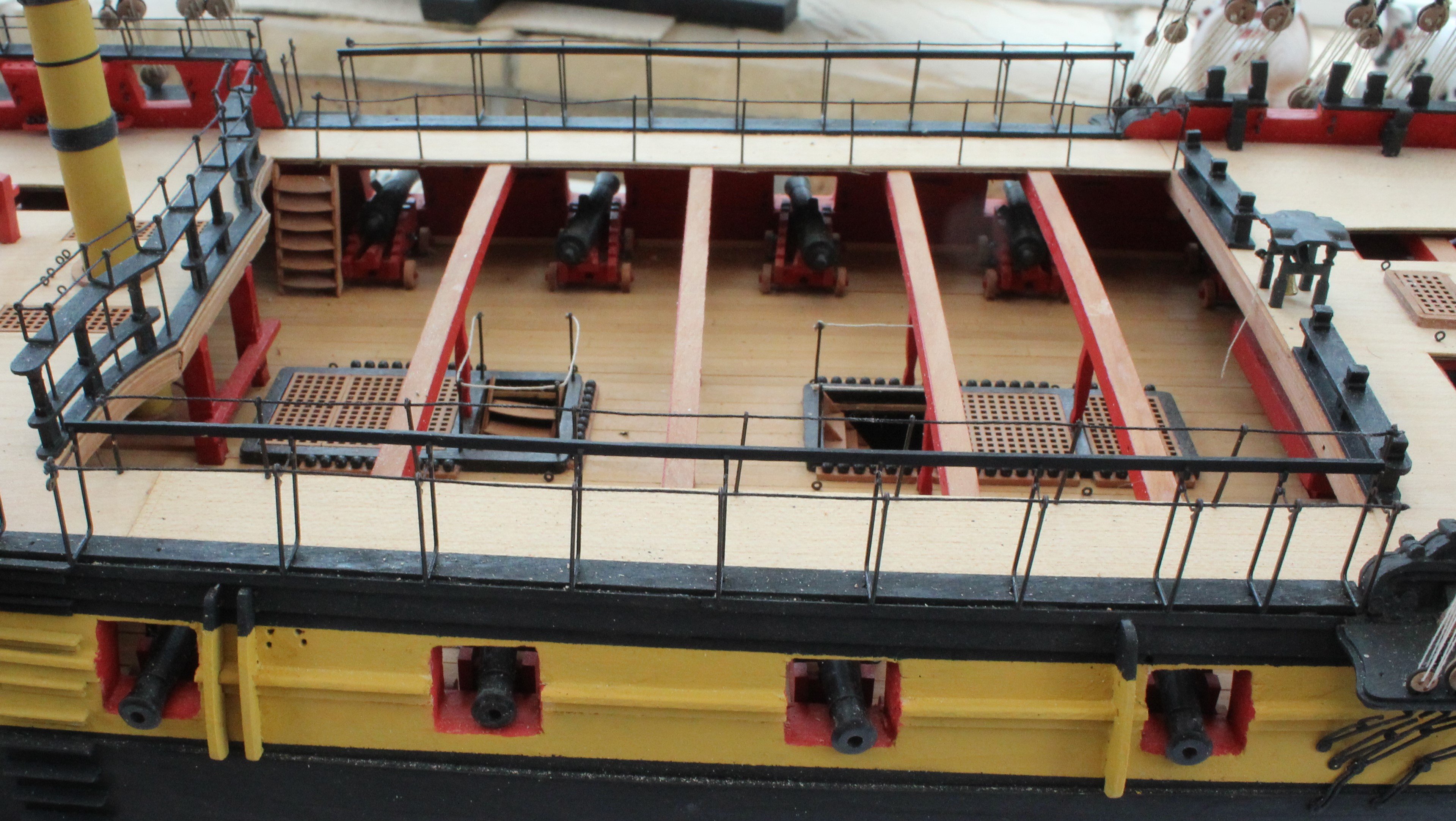
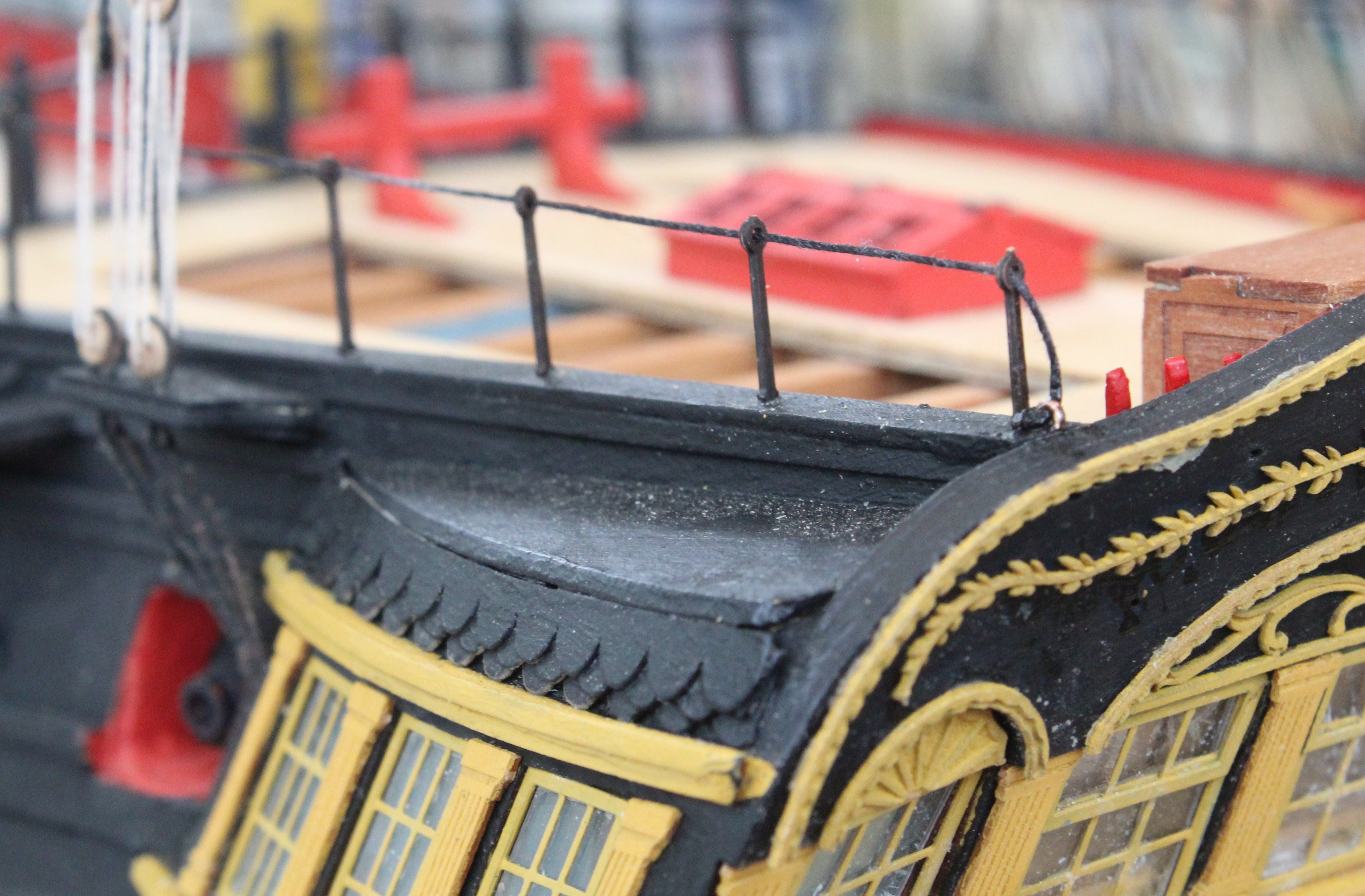
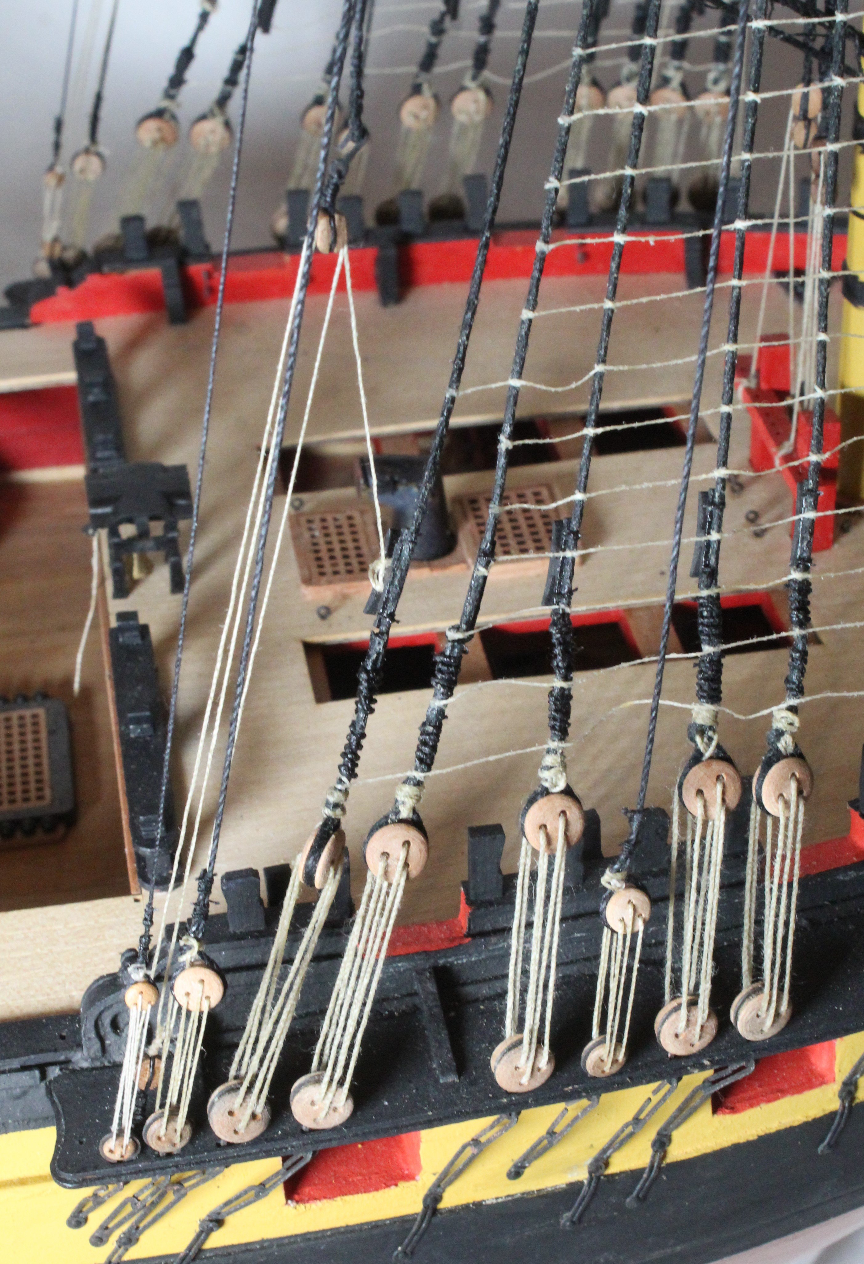
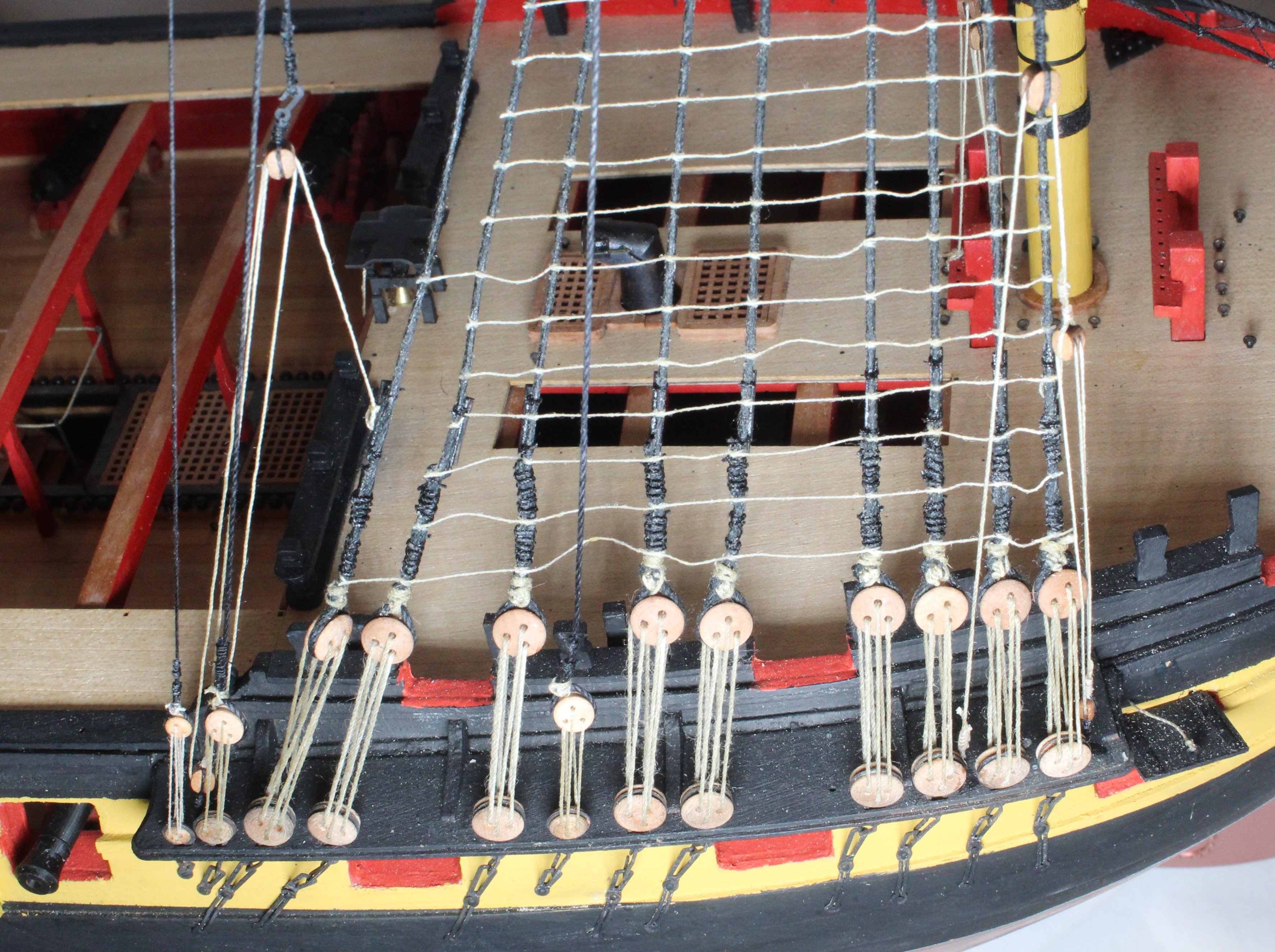
Mid Deck & Quarterdeck Bulwark Hammock Cranes and Poop Stanchions
After completing the backstays my next intended task was to add the two main stay tackles. However as I was looking at the rigging plans and the Indy to check the belaying points I noticed that I had not fitted the various hammock cranes and stanchions to the gunwales. Also I had not added the thread to the quarterdeck barricade hammock cranes.
The easiest task was to add the 0.5mm black thread to the quarterdeck barricade hammock cranes. A length of black thread was cut and run through my block of beeswax. I then used a hairdryer to melt the beeswax which helped to stiffen the thread. The thread was then added to the quarterdeck barricade hammock cranes.
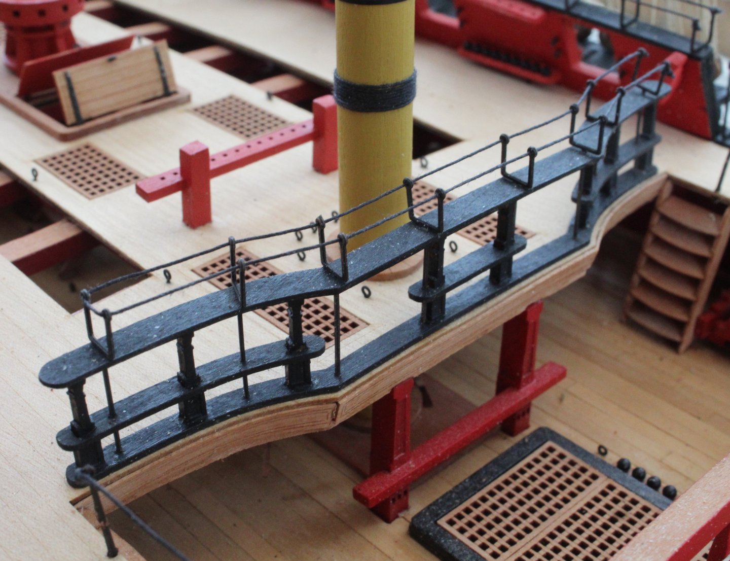
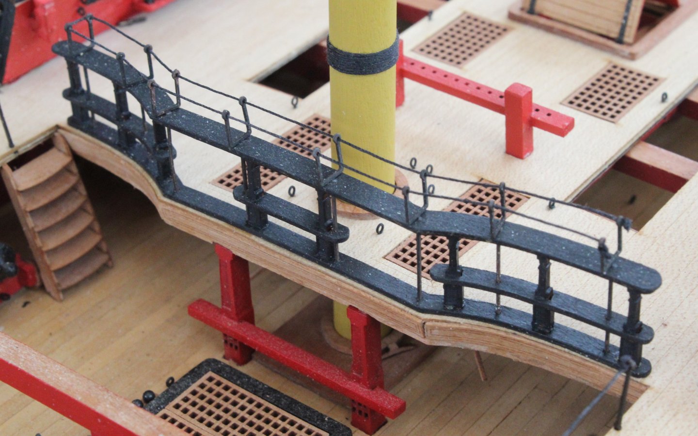
Next I moved on to the mid deck stanchions and hammock cranes. This uncovered another error with my build in that I had incorrectly fitted the mid deck gunwales, they were fitted back to front. If I fitted the hammock cranes in the holes provided the access to the Indy via the steps would be blocked. I simply added two new holes so the access via the steps was clear.
The inner stanchions were fitted and rigged first. Once they were done the hammock cranes were added. These cranes required a length of 2x1 to fitted as well as 0.5mm black thread.
The next task was to add the Quarterdeck Bulwark Hammock Cranes and Poop Stanchions. This was a bit more difficult to do as access to the gunwales was restricted by the shrouds and backstays. However I took my time and I was able to complete the task.

I am hoping to add the two main stay tackles tomorrow before I go away for a few days so on my return I can then start work on making the various yards and booms.
-
-
-
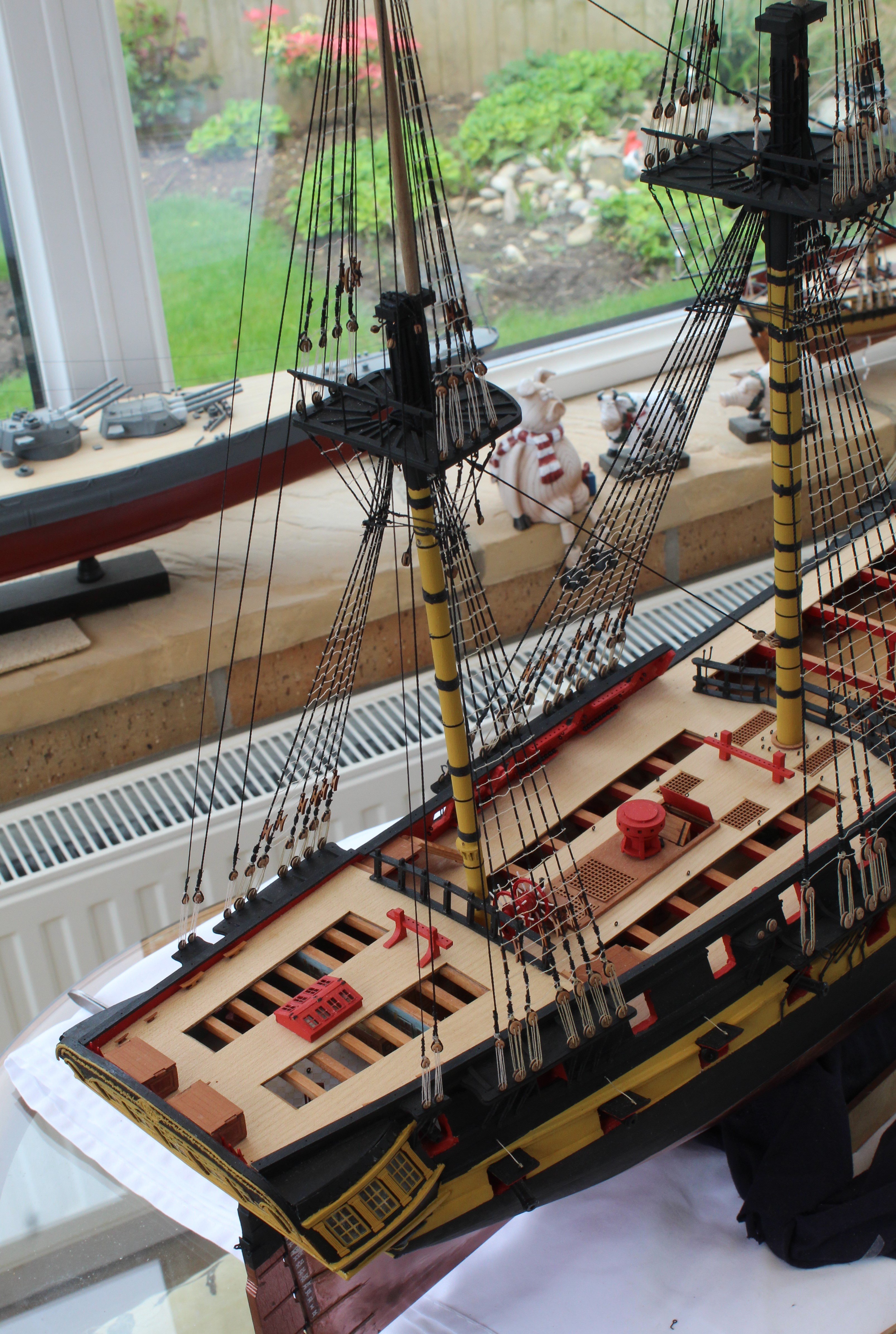
Backstays
I have now completed all work related adding the various backstays.
Here are a couple of photo's showing the current build status, they are not great photos.
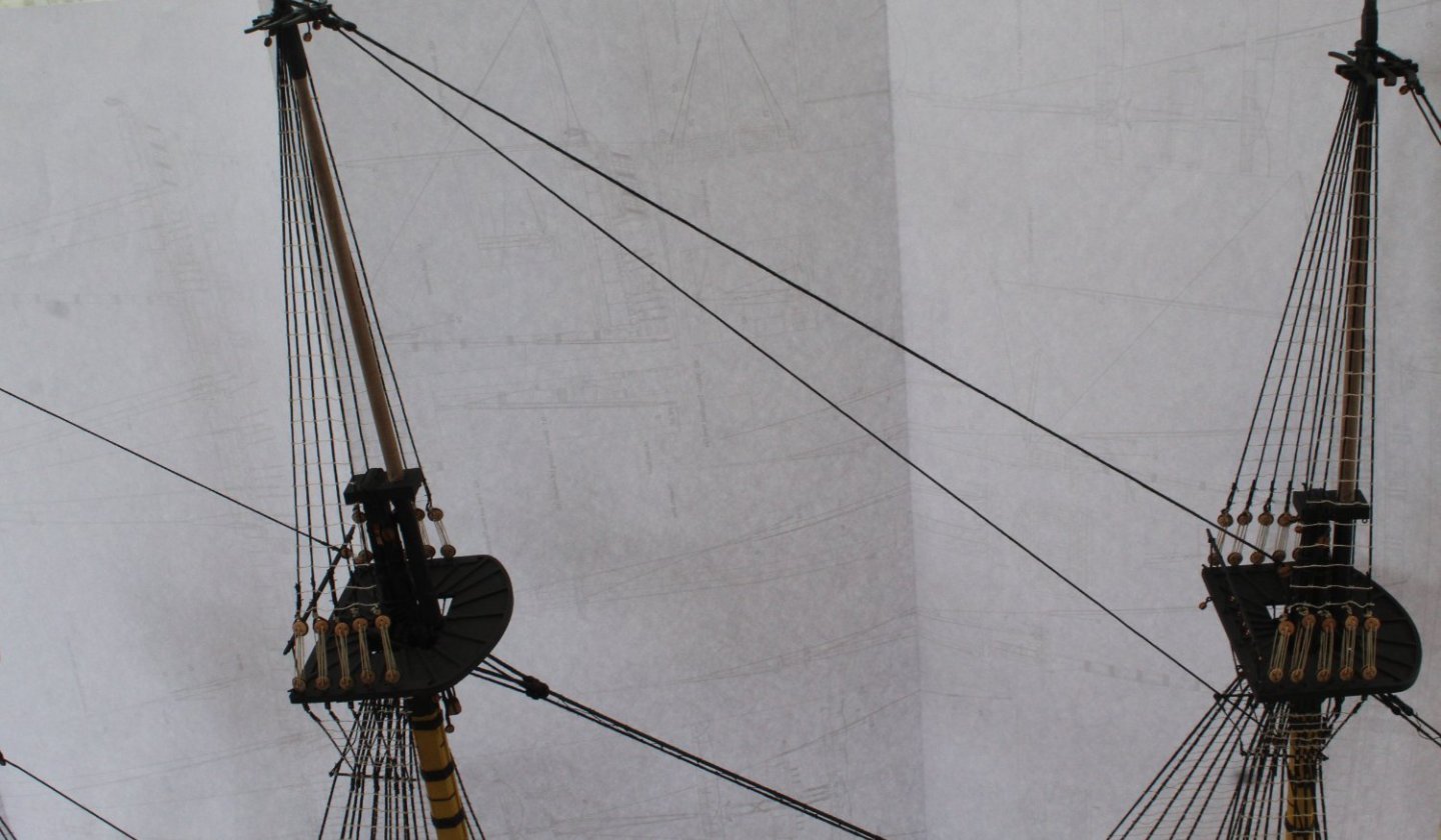
The next photo shows the fore mast breast backstay.
The next two photo's show the shifting backstays and the topsail and topgallant backstays


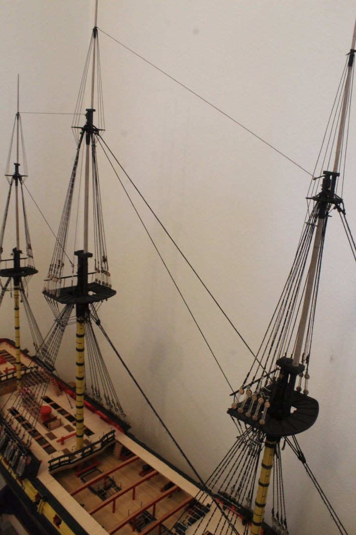
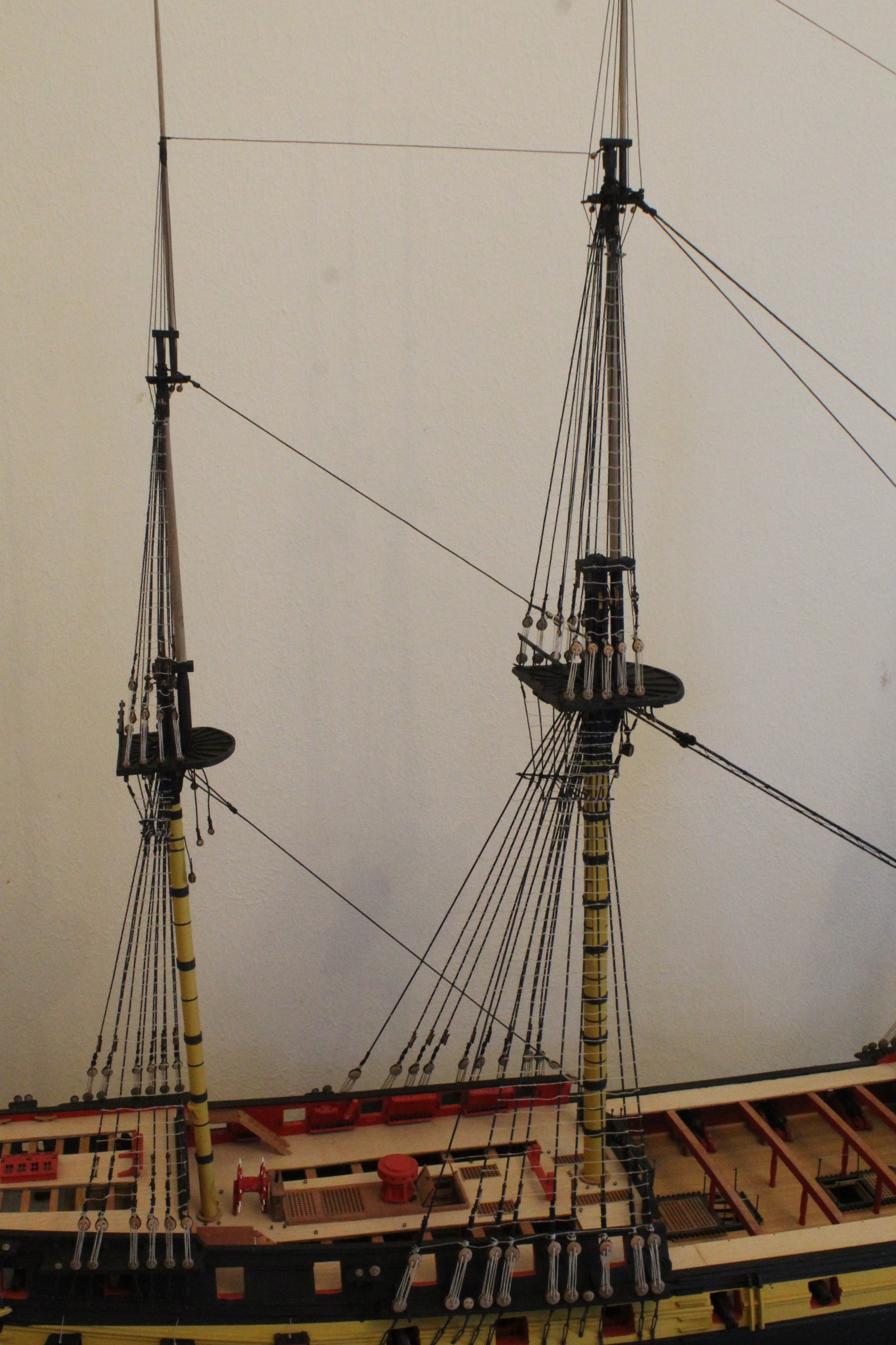
The final photo shows the entire lower foremast with shrouds and backstays fitted.

My wife and I have booked a short holiday for next week so I'm not expecting to make too much progress before we depart.
-
Main mast breast and shifting backstays, main topsail mast back stay and main topgallant mast backstay
After a few days work all the various backstays required for the main mast, the main topsail mast and main topgallant mast have been rigged and belayed. I am very pleased with how the Indy is now looking. Moving forward the next few days will be spent adding the various backstays for the fore mast, the fore topsail mast and fore topgallant mast. I have attached a photo of the completed main backstays.
The next two photos show the completed breast backstays, which have now been belayed to one of the main shroud cleats.
The photo shows shifting backstay and the topsail and topgallant backstays.
The next photo shows the belaying of the shifting backstay to a belay pin
The final photo is a close up of the shifting stay eyebolt and block
-
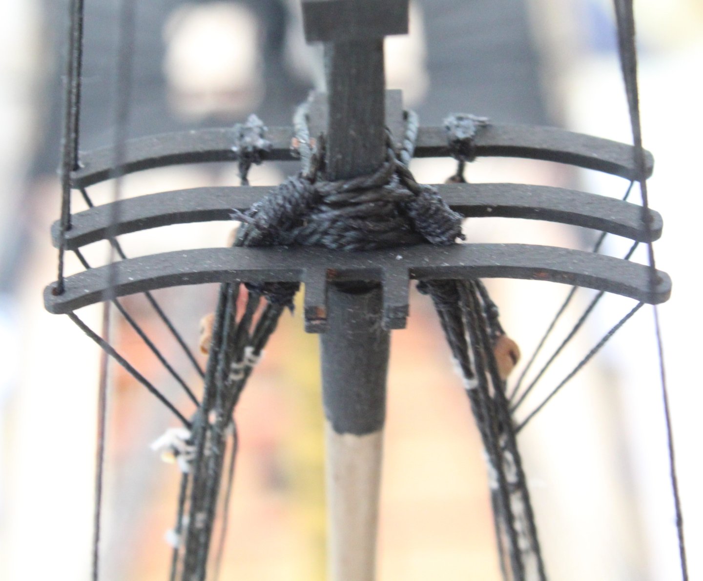
Main Breast Backstay Installation
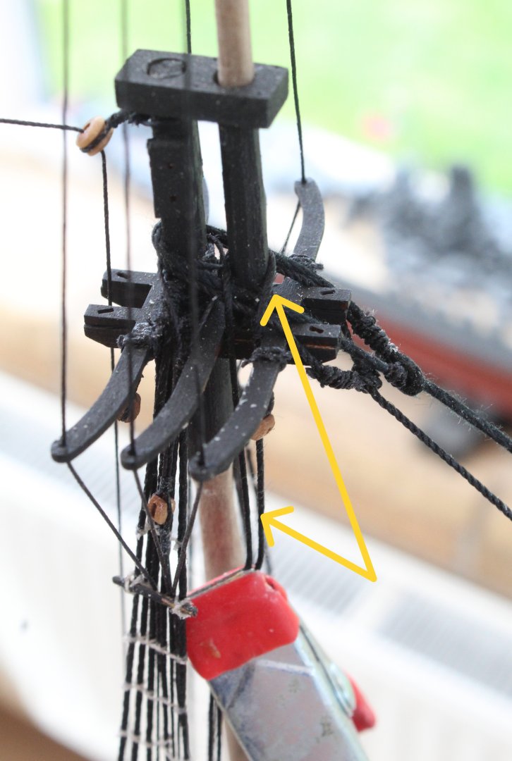
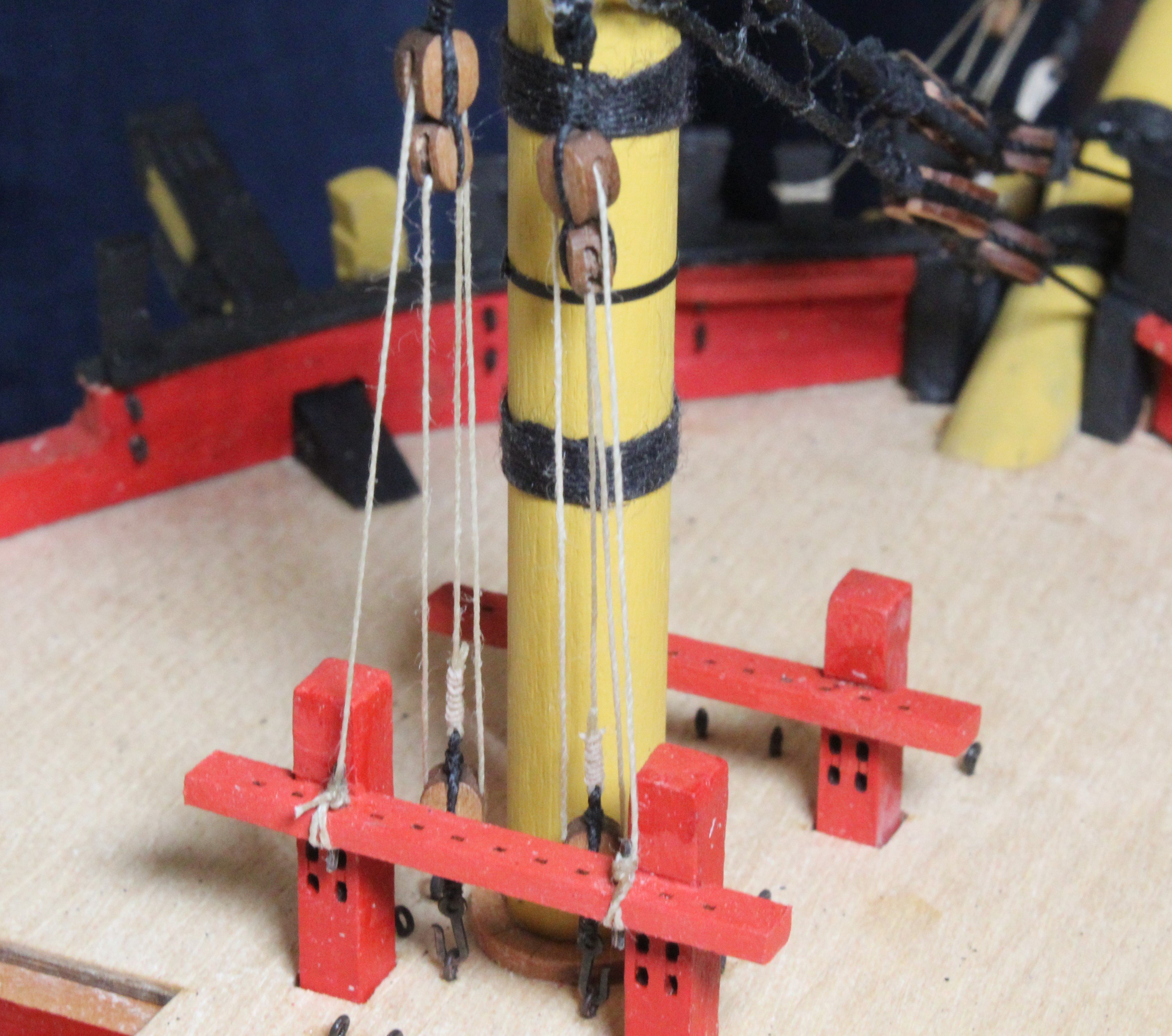
Following on my last post I thought I would share the method I used to install the main breast backstay. With reference to the photo below I started by wrapping the backstay around the main topgallant mast and adjusted the height of the block seized to the end of the backstay to the required height. Once I was happy with the position I used a clamp to hold the backstay in the required position.
Maybe I should have seized it to the main topsail mast rather than the main topgallant mast but I am happy with what I have done therefore there is no need for anyone to comment on this aspect / error.
The eyebolts were dry fitted to the main channel, and clamps were used to hold them in place.
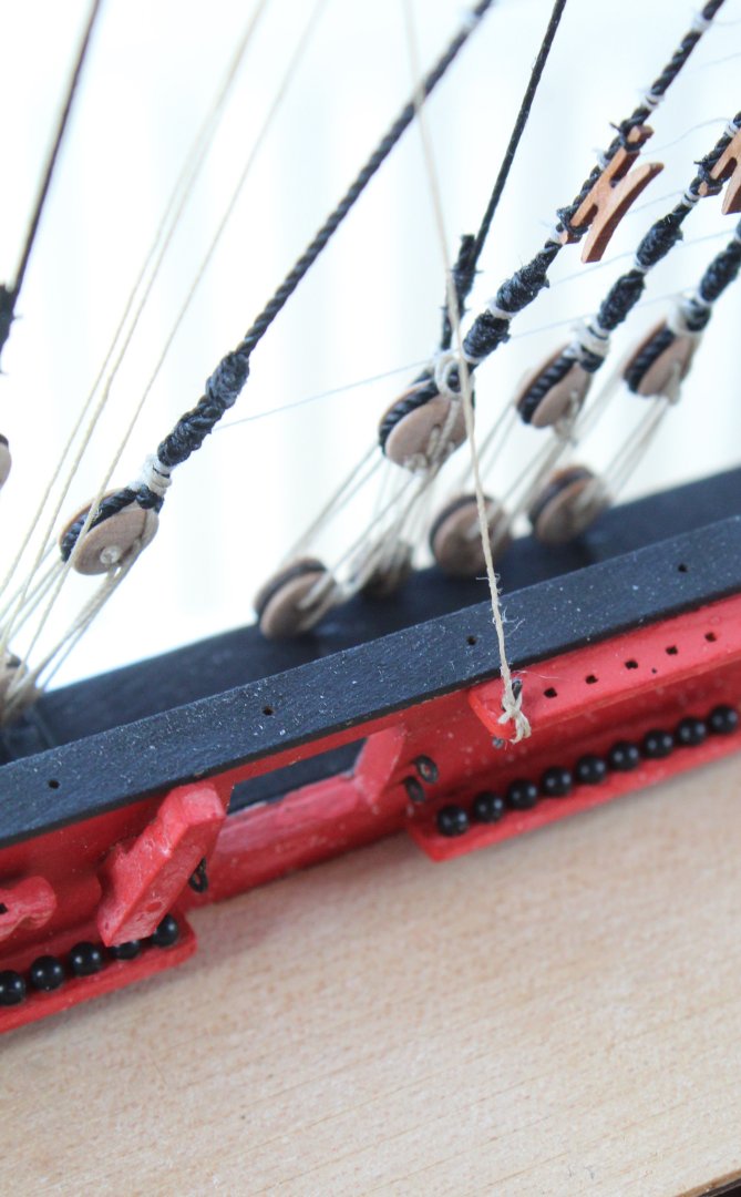
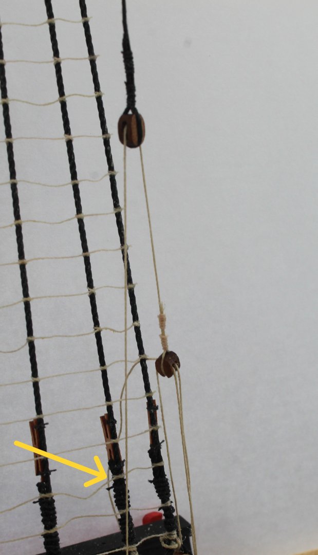
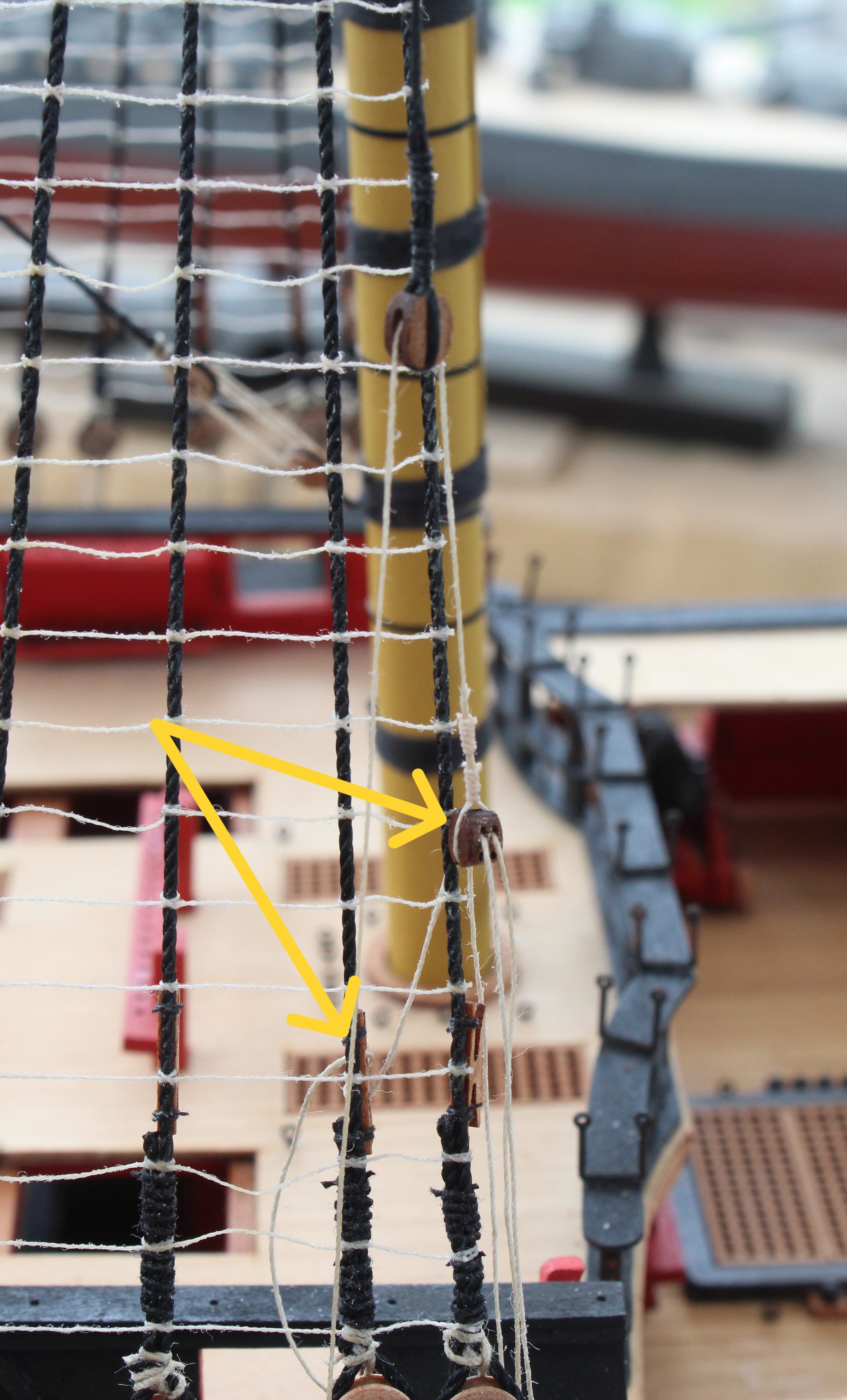
In the next photo the inter-block rigging has been added so that the lower block position could be checked with regards to the final belaying point, which is one of the shroud cleats, 2nd one in from the right as indicated by one of the yellow arrows.

Once I was happy with how everything looked the inter-block rigging was removed and then the backstay was seized, as shown by the yellow arrow.
Next the two eyebolts were glued in place. I did trim and then bend the excess eyebolt material under the channel.
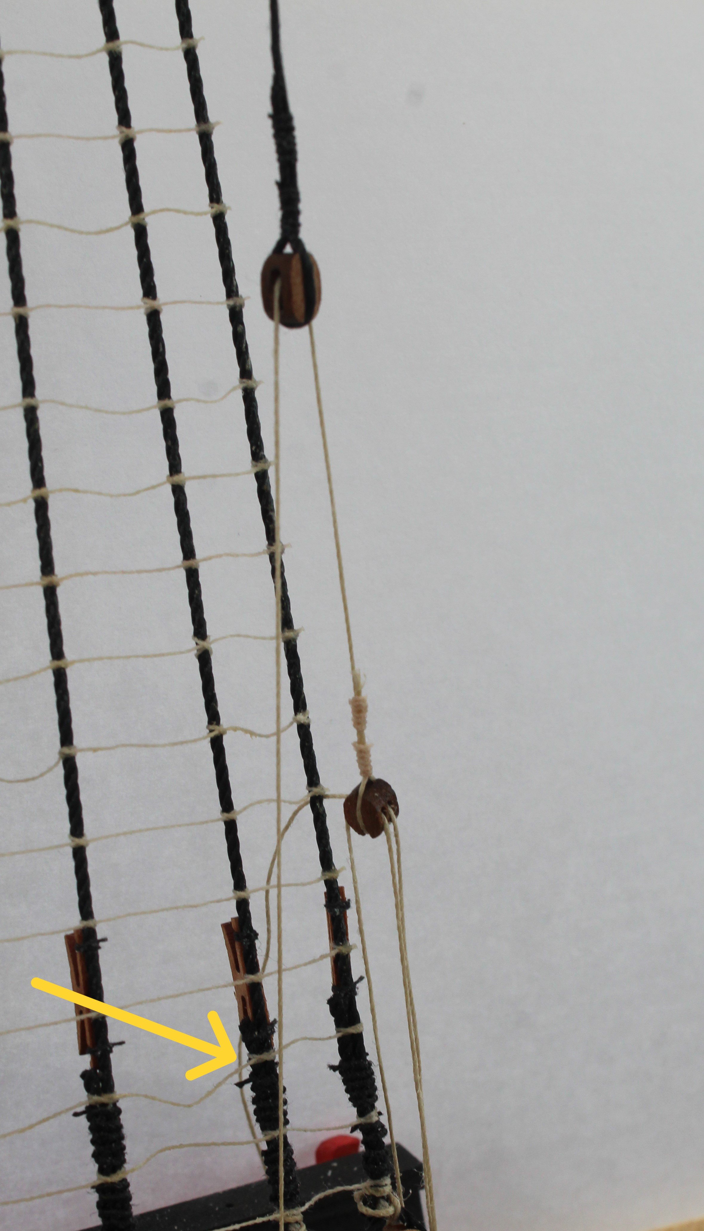
The inter-block rigging was then added and the backstay was tensioned. I will belay the rigging to the shroud cleat later on in the rigging process. The un-belayed end of the rigging thread is indicated by the yellow arrow.
-
Mizzen Mast Backstays
I seem to have spent quite a bit of time in the shipyard but there is no much sign of any real progress.
I am currently working on adding the various backstays and the preparation work is quite time consuming. I have moved the Indy to a different work area which allows me all round access which is much better when adding the rigging. The down side is it not possible to take good photos due to the open backgrounds.
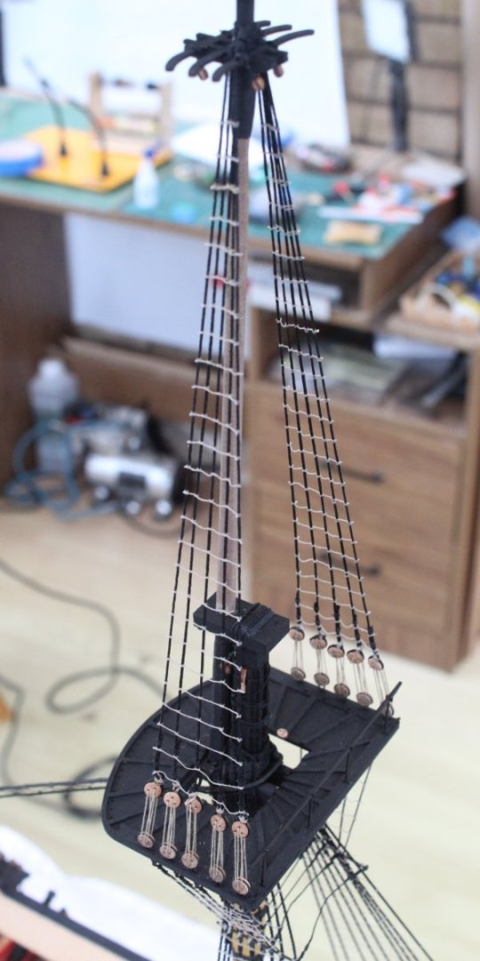
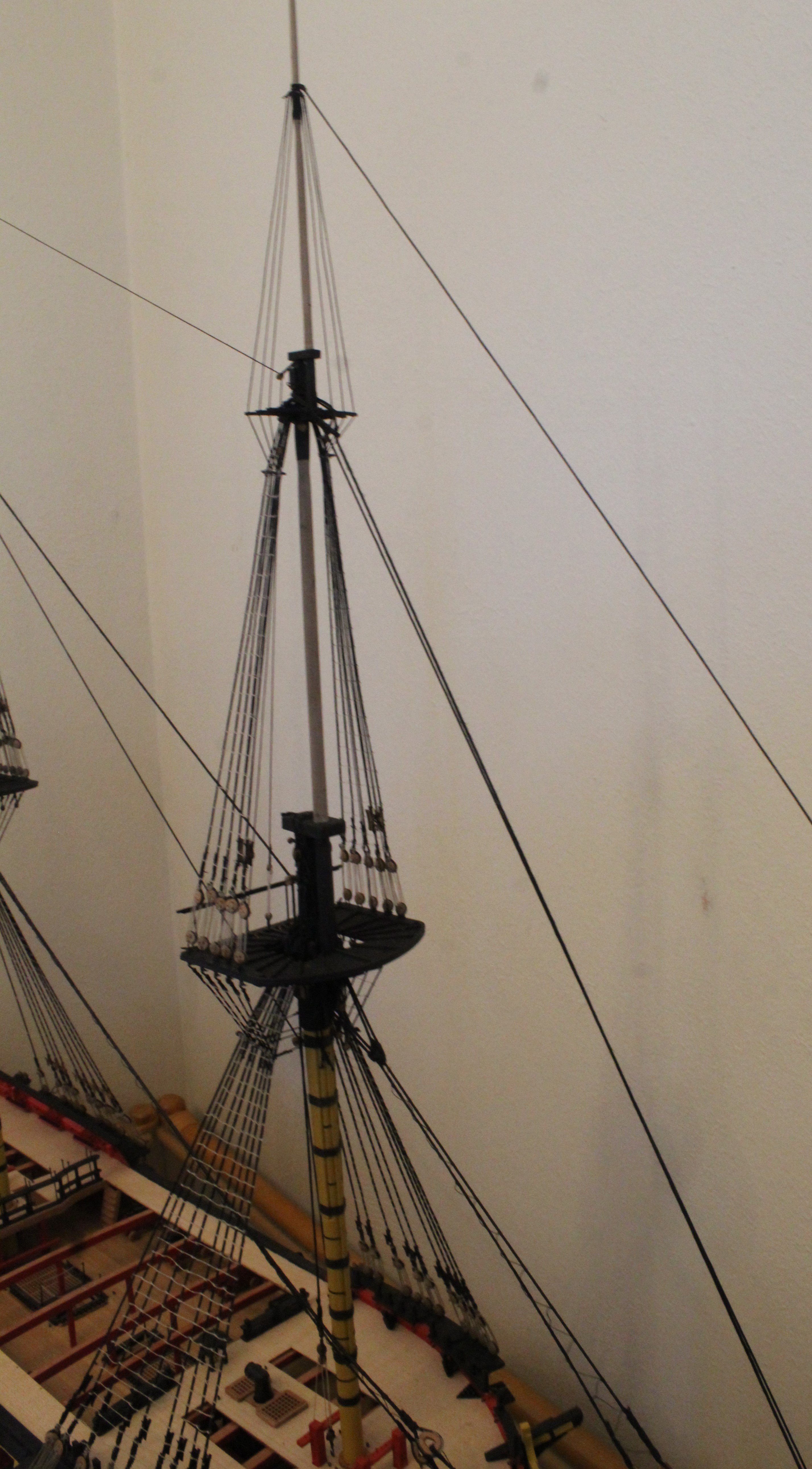
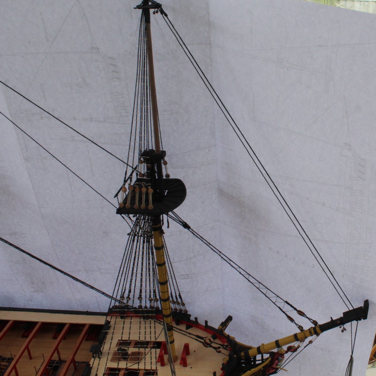
I started with the mizzen mast and this was the best photo showing the mizzen topsail and topgallant backstays.
Taking close up pictures is not such a problem and the next photo shows the upper mizzen topsail mast platform where the topsail backstays are positioned and dropped down through the rear crosstrees.
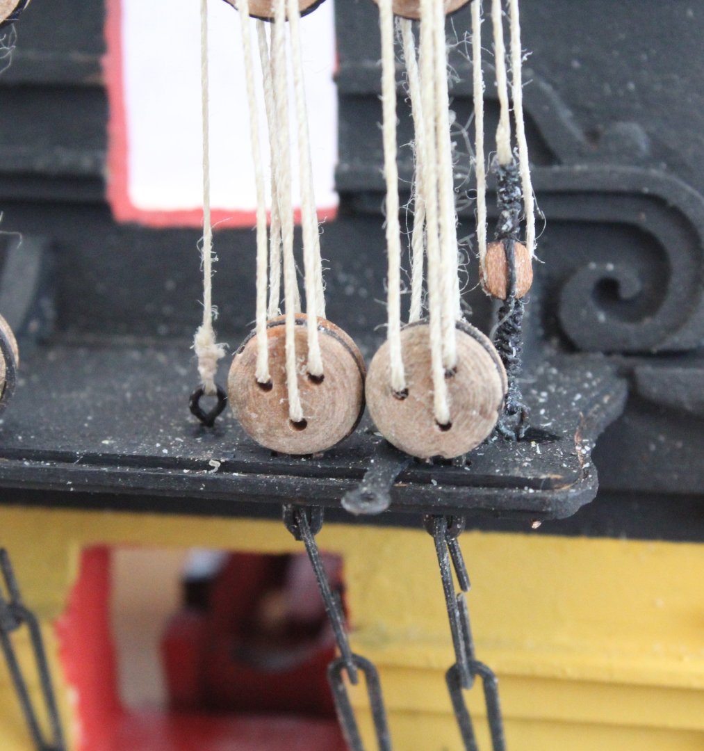
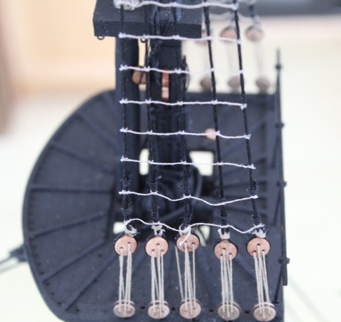
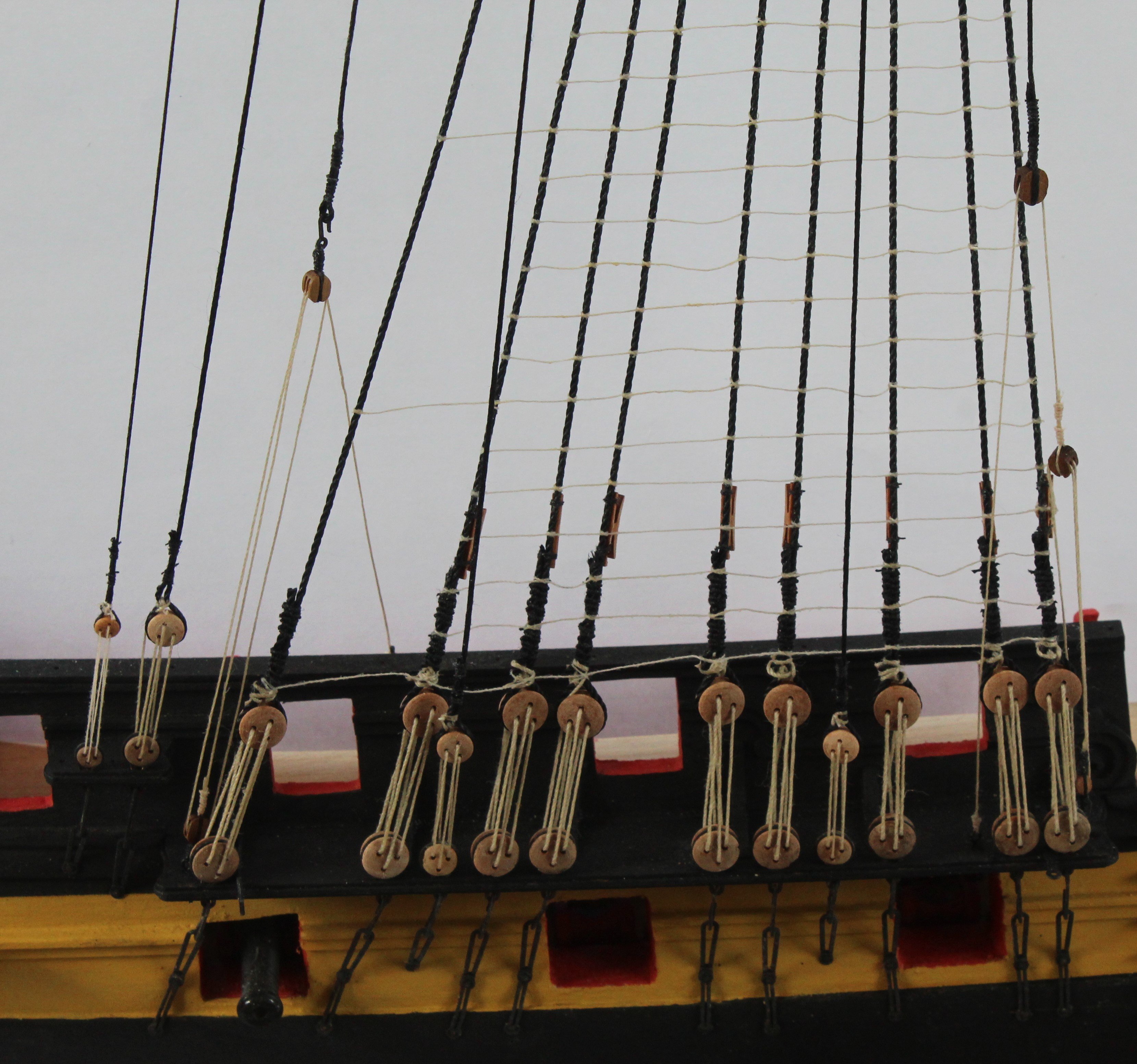
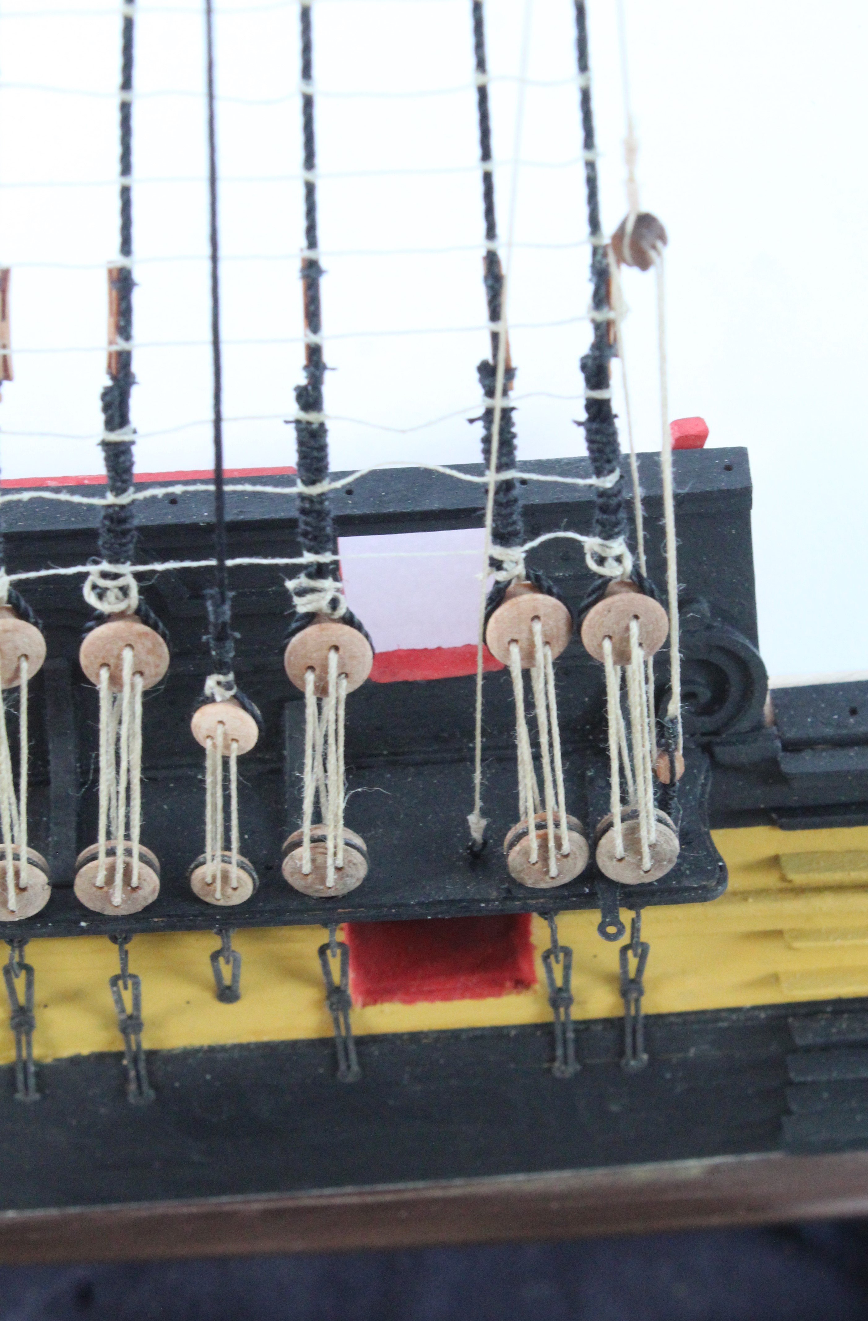
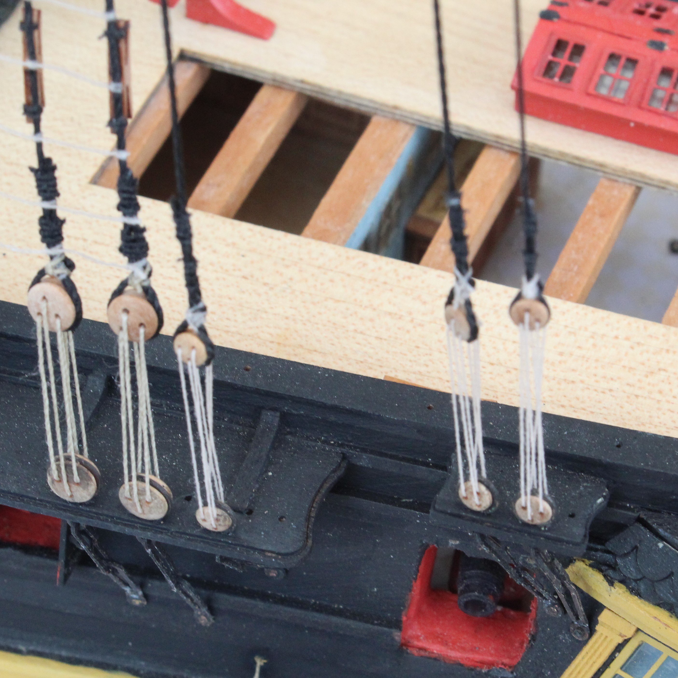
And now a photo showing the backstay deadeyes.

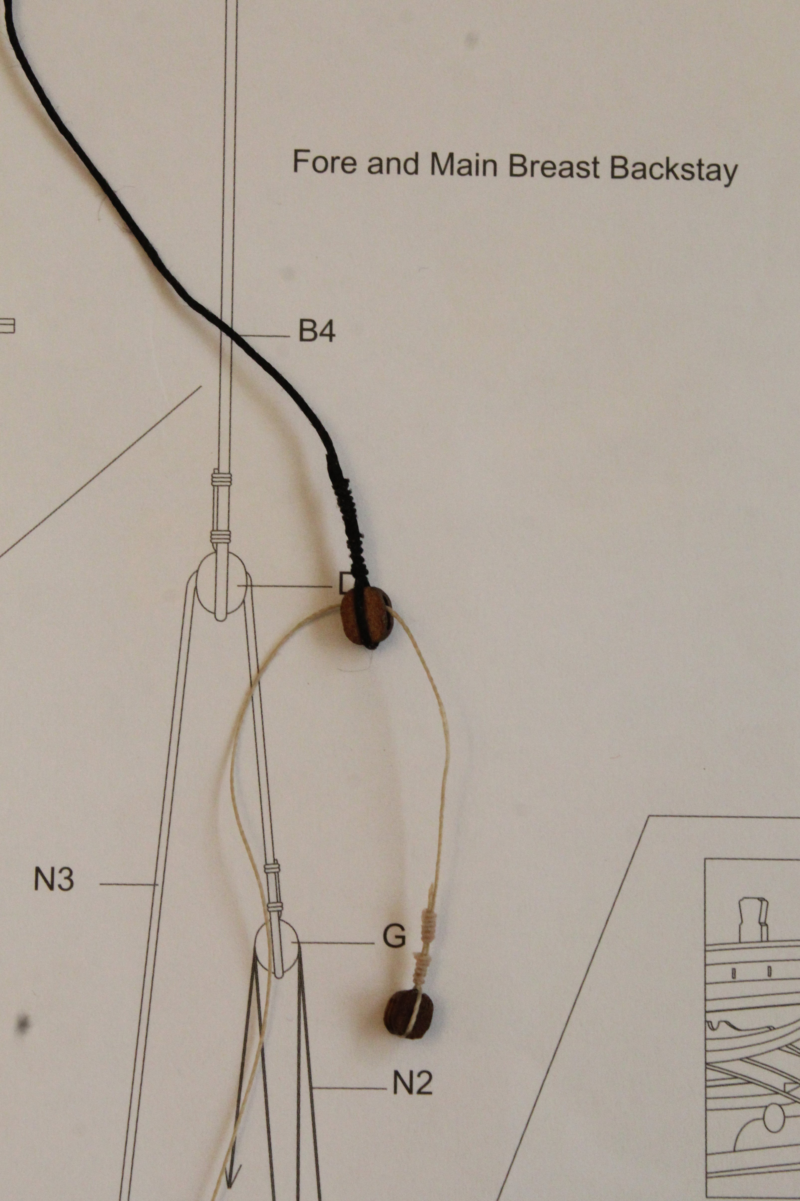
Main Mast Breast Backstay
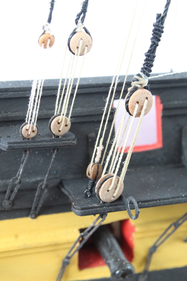
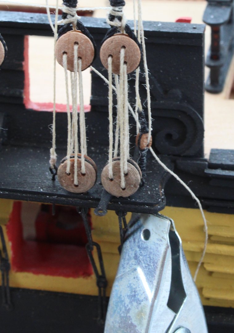
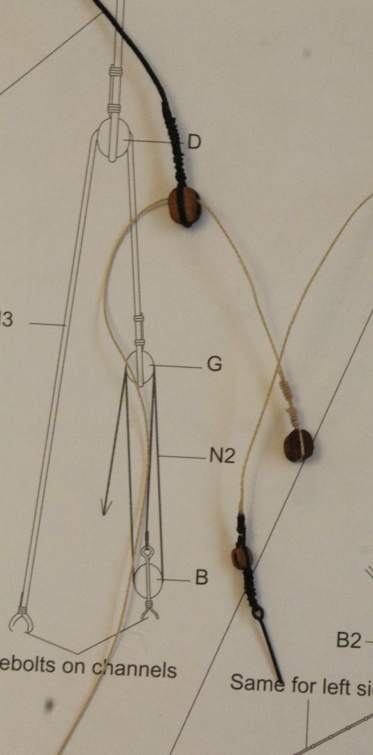
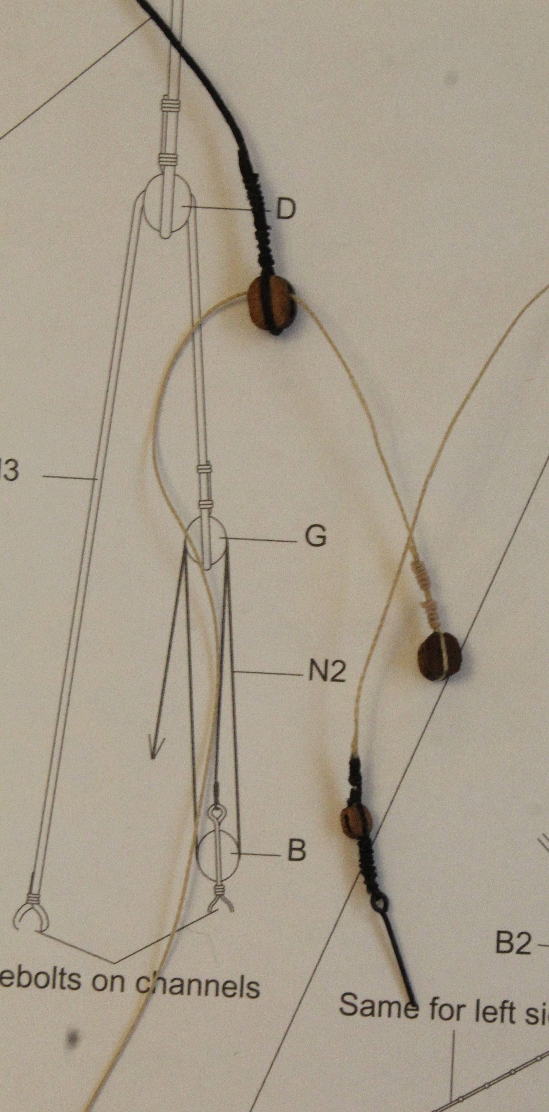
The fore and main breast backstays are quite involved, each requiring a three block belaying arrangement. In the next photo I have shown the two upper blocks.
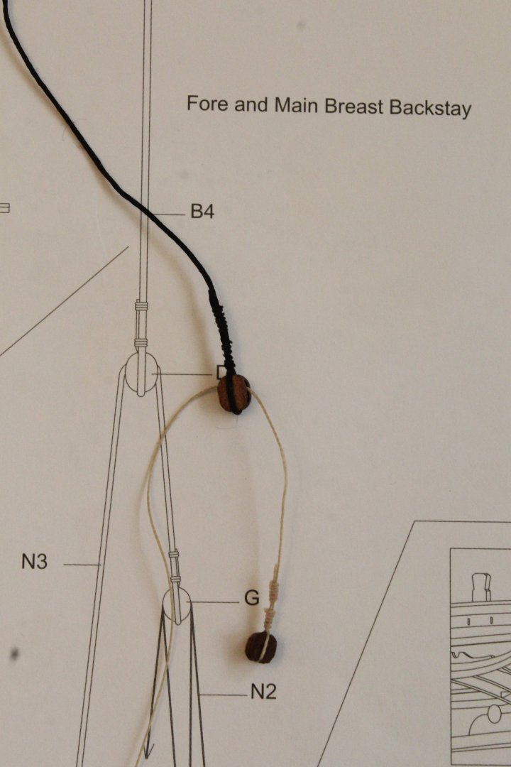
The next shows all three blocks and this backstay arrangement is now ready to be installed. However before I do this I need to make up the other 3 breast backstays arrangements.
- KurtH, Thukydides, ECK and 7 others
-
 10
10
-
Stays and Preventors
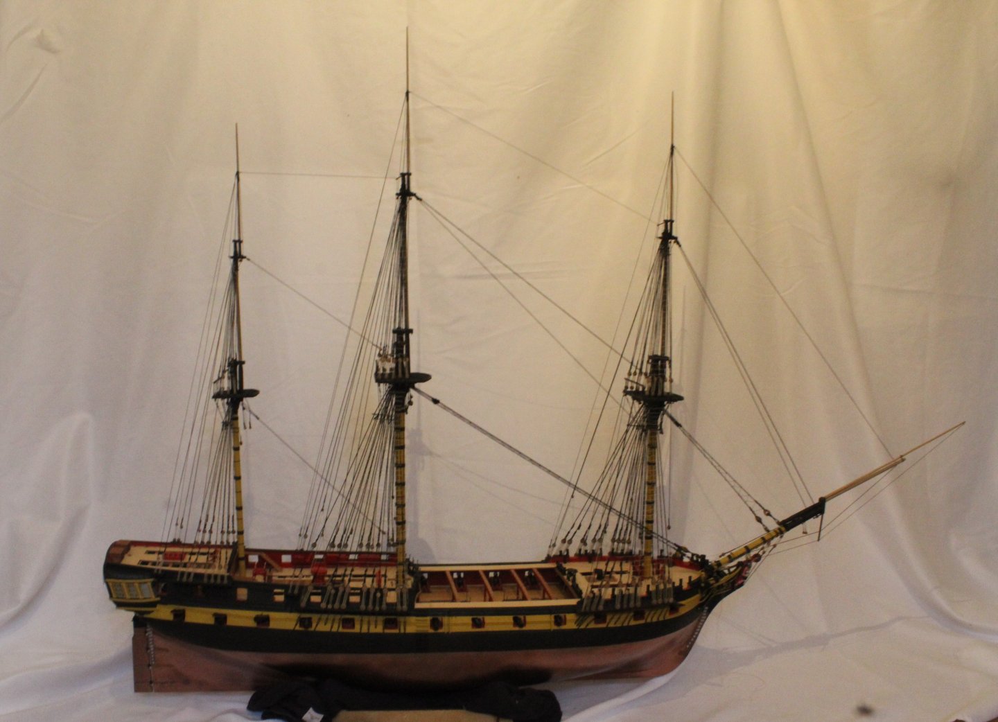
I have finally completed adding all the stays and preventors for the mizzen, main, and fore lower, topsail and topgallant masts. The sprit topmast and flying jibboom have also been added to the bowsprit.
I am reasonably happy with how the Indy is looking at the moment. There is still a few more months work ahead required to complete the build.
The first photo shows the Mizzen mast.

The next photo shows the belaying arrangement for the mizzen topsail and topgallant stays, located on the main mast lower platform. I did have to redo the mizzen topsail stay as I was not very happy with the end result after I had added the mizzen topgallant mast stay.
The next photo shows the main mast stays
The next photo shows the main topsail and topgallant stays belaying arrangement on the foremast lower platform
 The next photo shows the belaying on the main topsail stay and preventor at deck level.
The next photo shows the foremast stays

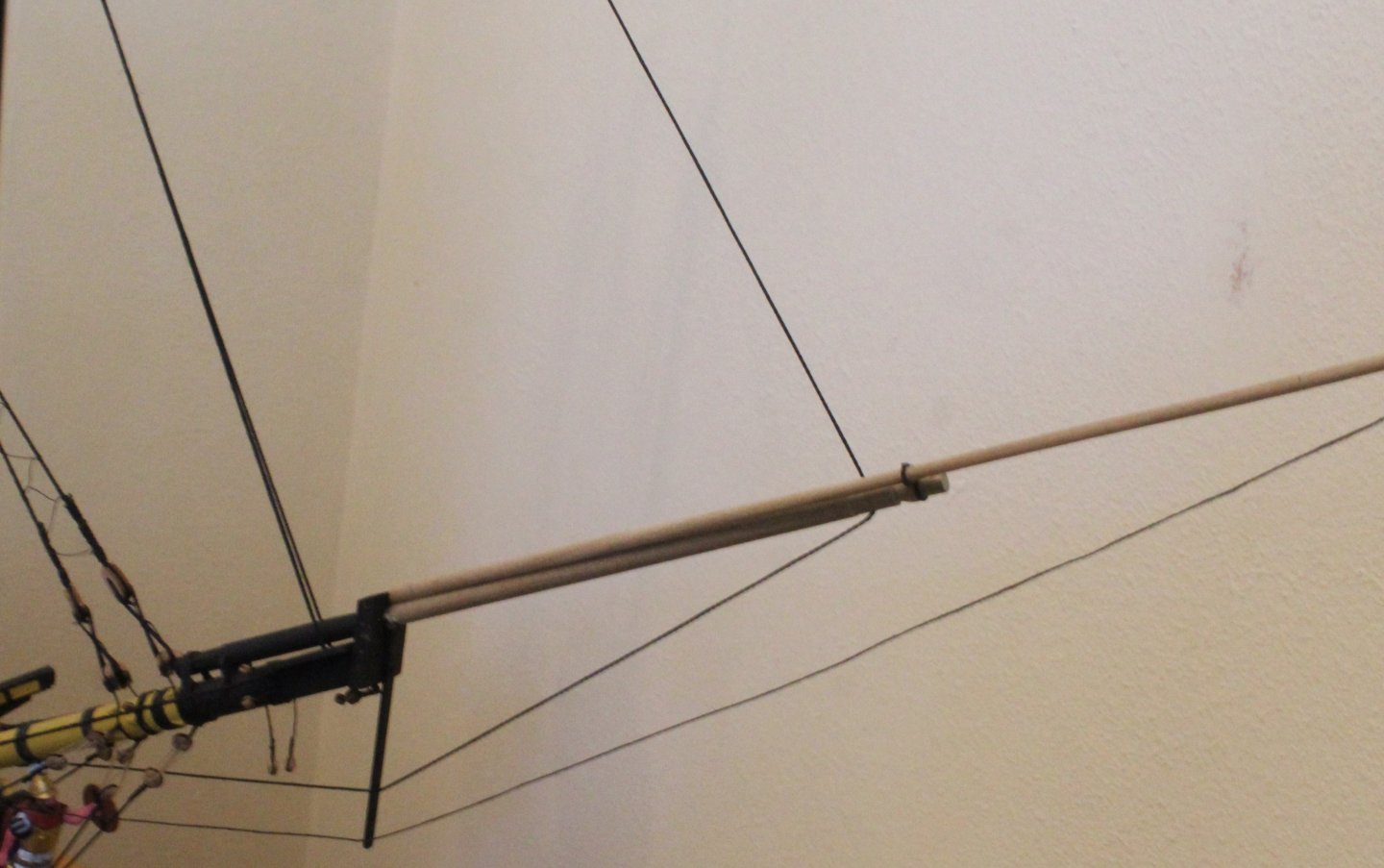
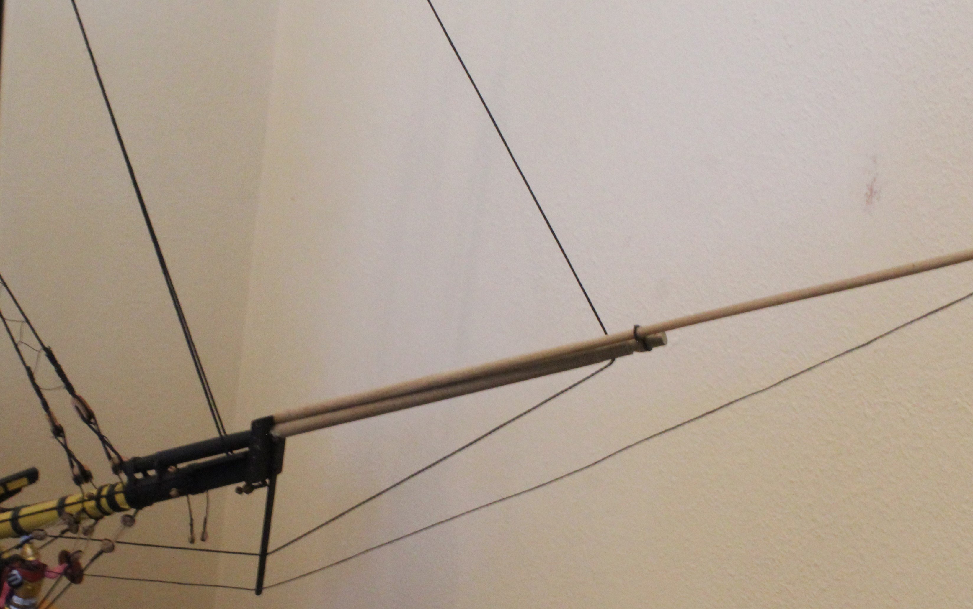
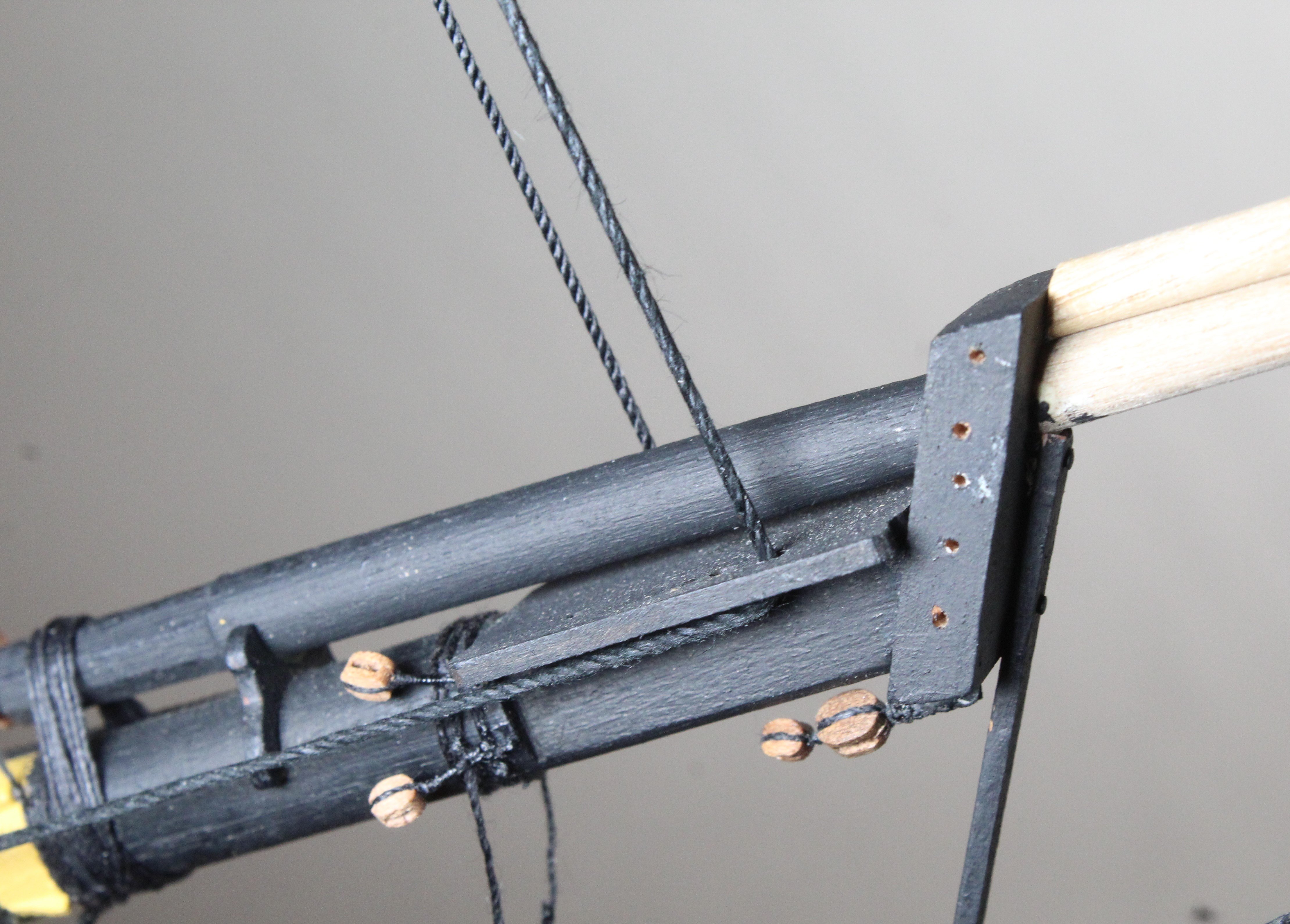
The top gallant stay and flying jibboom stays are fed through the dolphin striker, as shown in the next photo.
The fore topsail stay and preventor are taken through the bees, as shown in the next photo.
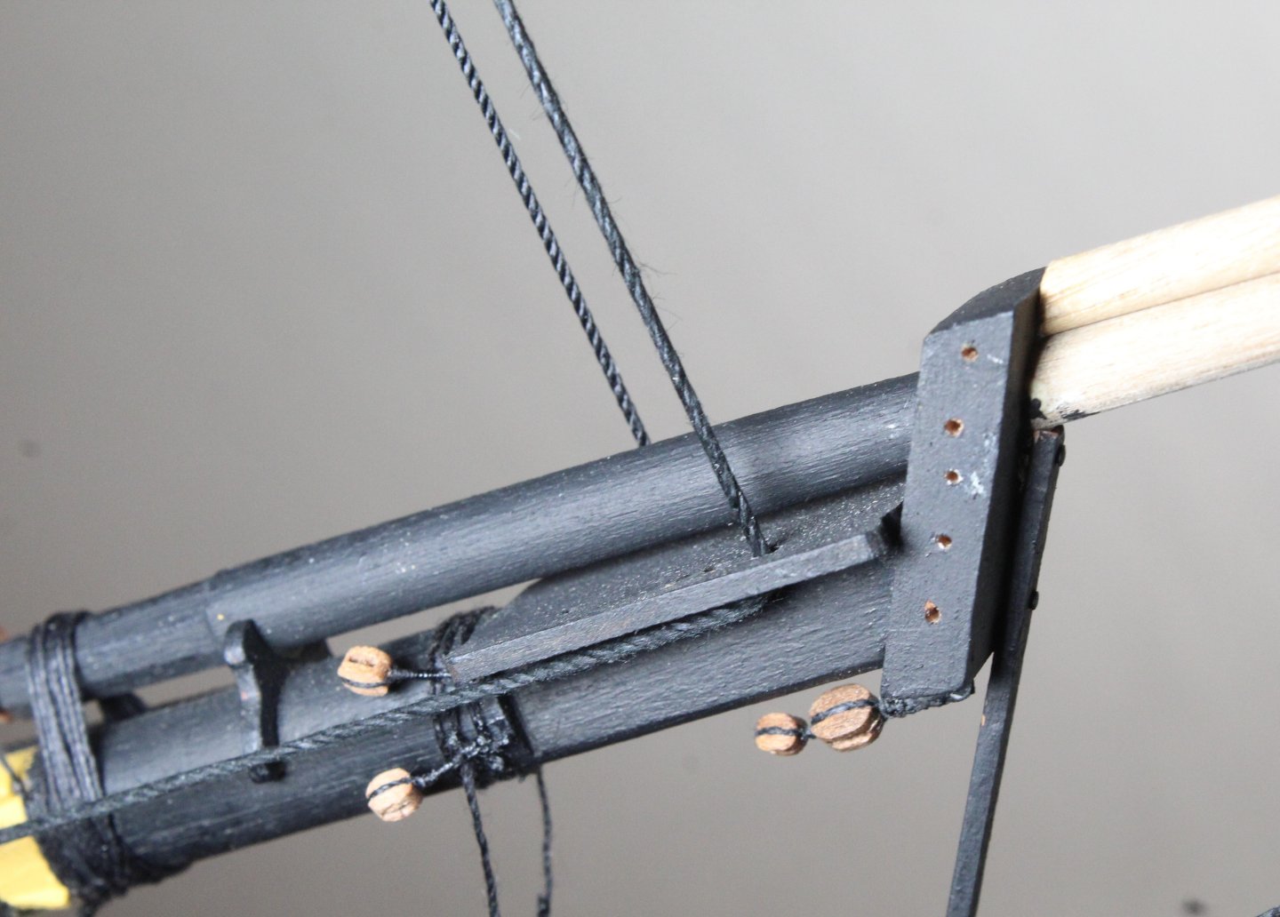
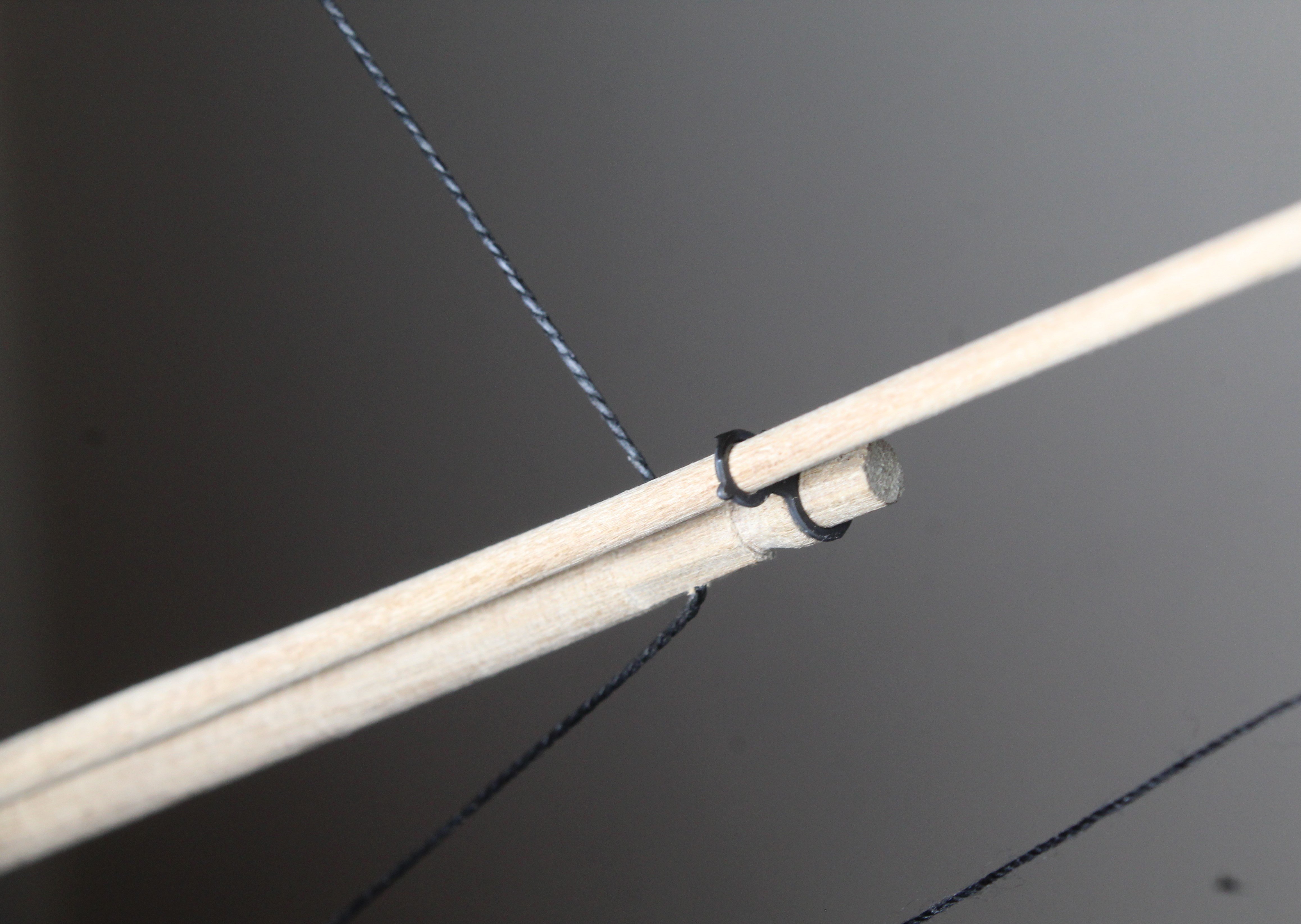
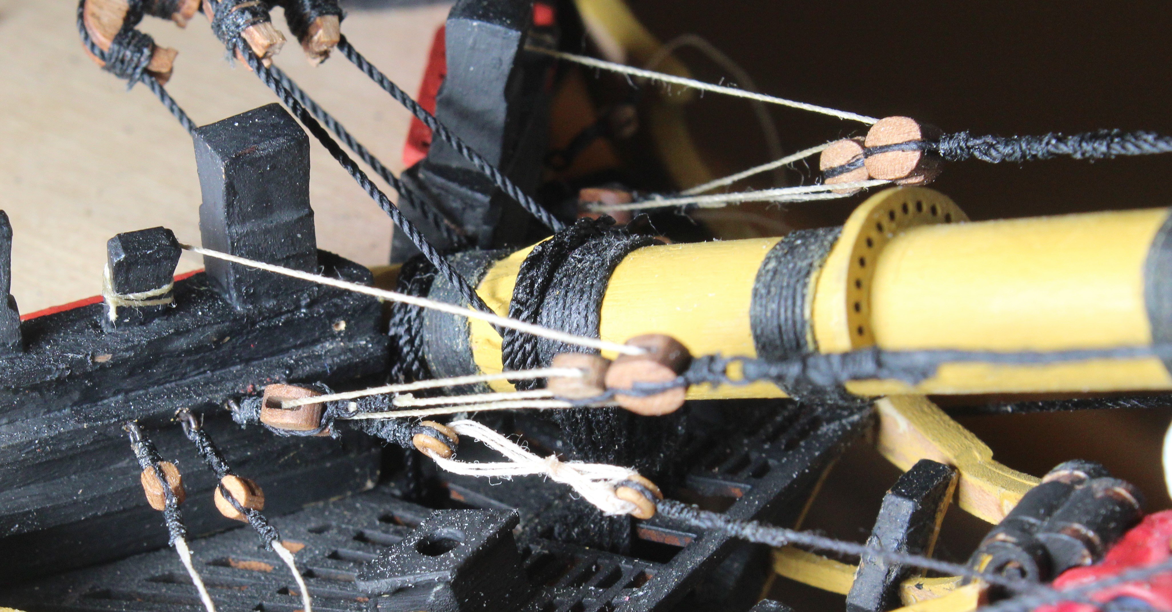
Some close up detail of the sprit topmast and flying jibboom arrangements in the next couple of photos.
The next photo shows the fore topsail preventor and flying jibboom belaying arrangement at the bow. There is a similar belaying arrangement on the port side bow for the fore topsail stay and fore topgallant stay,

- Blue Ensign, RossR, ECK and 6 others
-
9
-
Congrats on completing a superb build.
- mtaylor, Blue Ensign and Mr Whippy
-
2
-
 1
1
-
Enjoying your progress. I think the Brig Adder will be my next build once I have completed the Indy in a few months time. I really like the look of the curved bow.
- AJohnson, chris watton and Mr Whippy
-
3
-
30 minutes ago, AON said:
Just wondering...
I wonder why a set of blocks nested end to end was used as opposed to a fiddle block?
...not expecting an answer, unless someone knows!
In answer to your question, I have no idea.
-
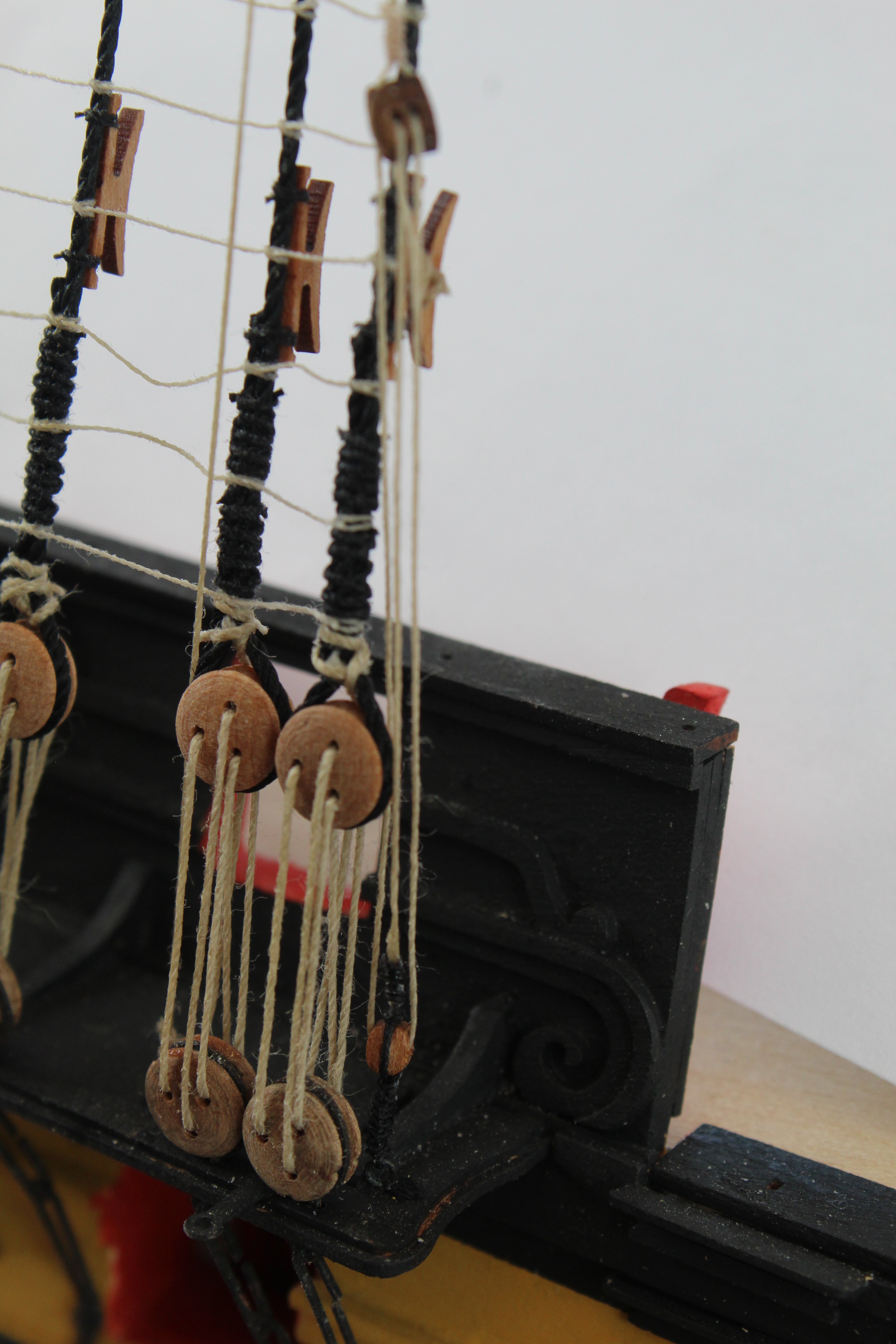
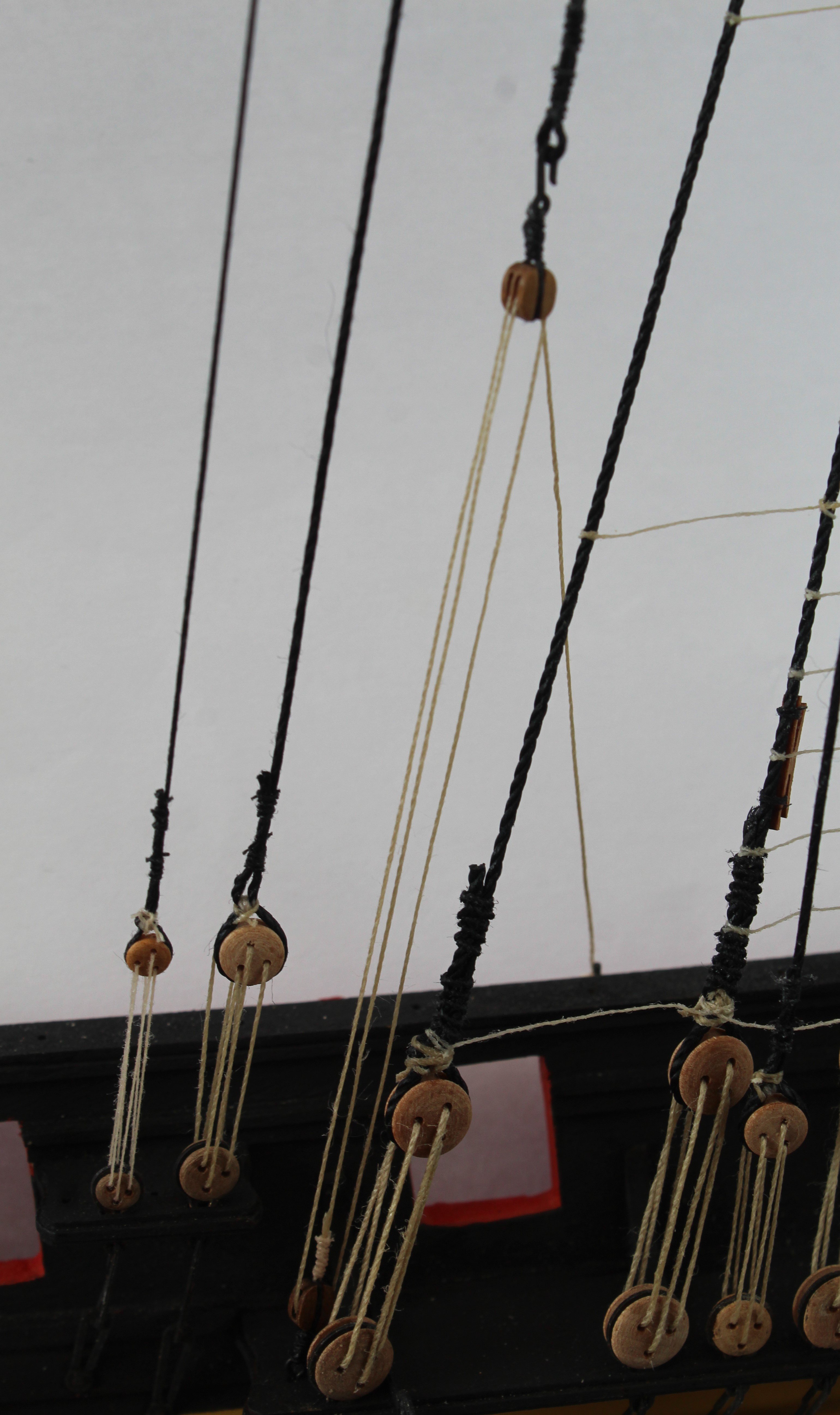
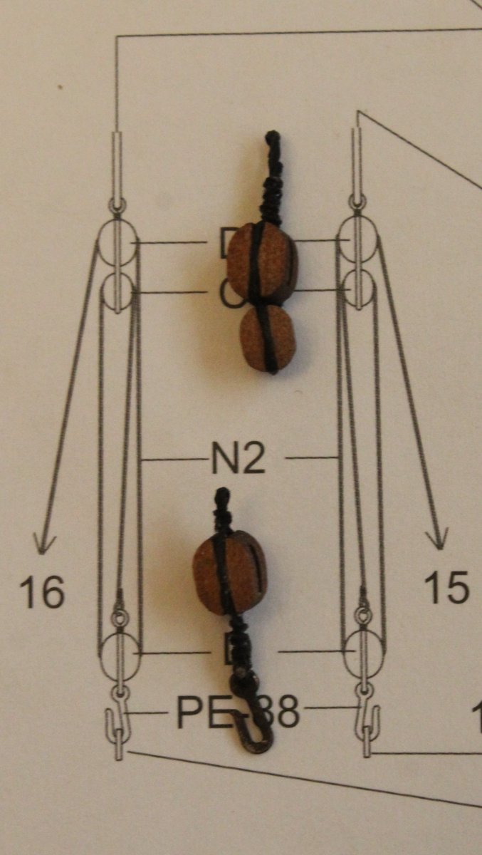
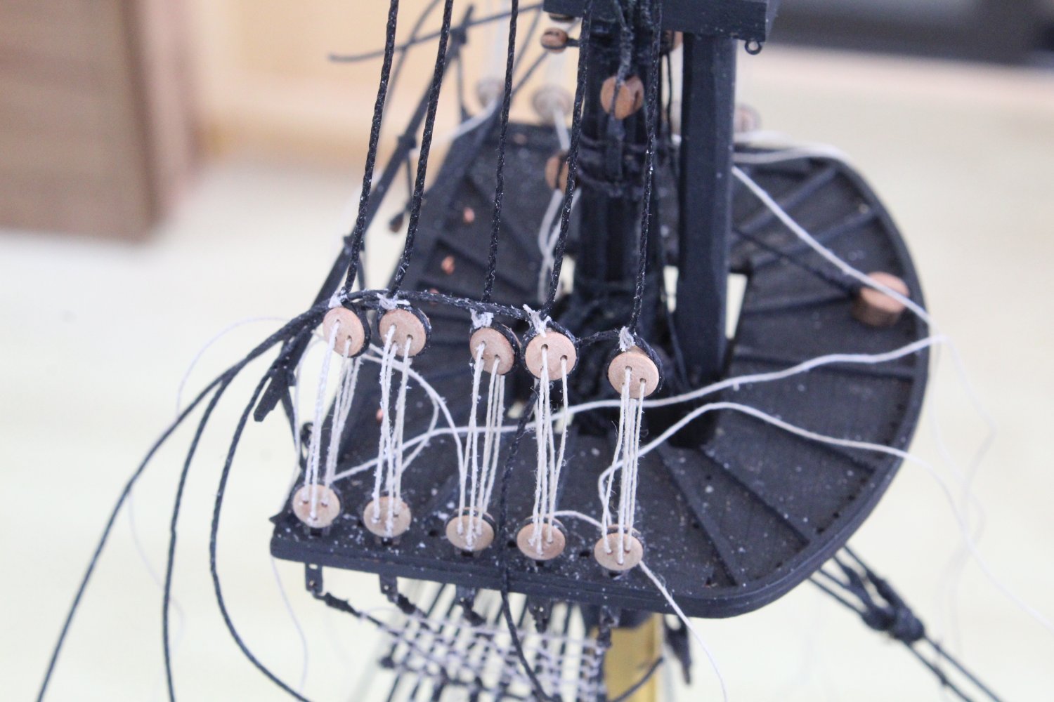
Main and Fore Topsail Mast Stay Belaying Blocks
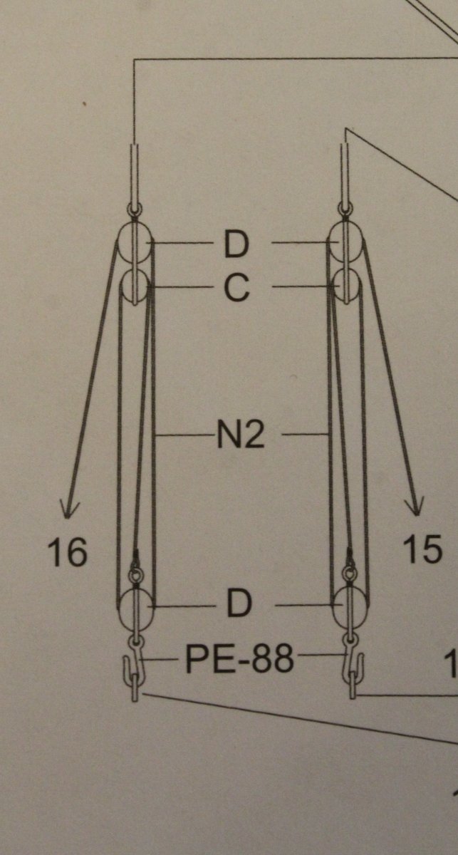
As indicated in my previous post the belaying of the main and fore topsail mast stays are via a blocking arrangement, as can be seen in the photo below. The smaller lower block requires a thimble and hook adding. The upper section consists of two blocks, with a thimble added to the larger top block.
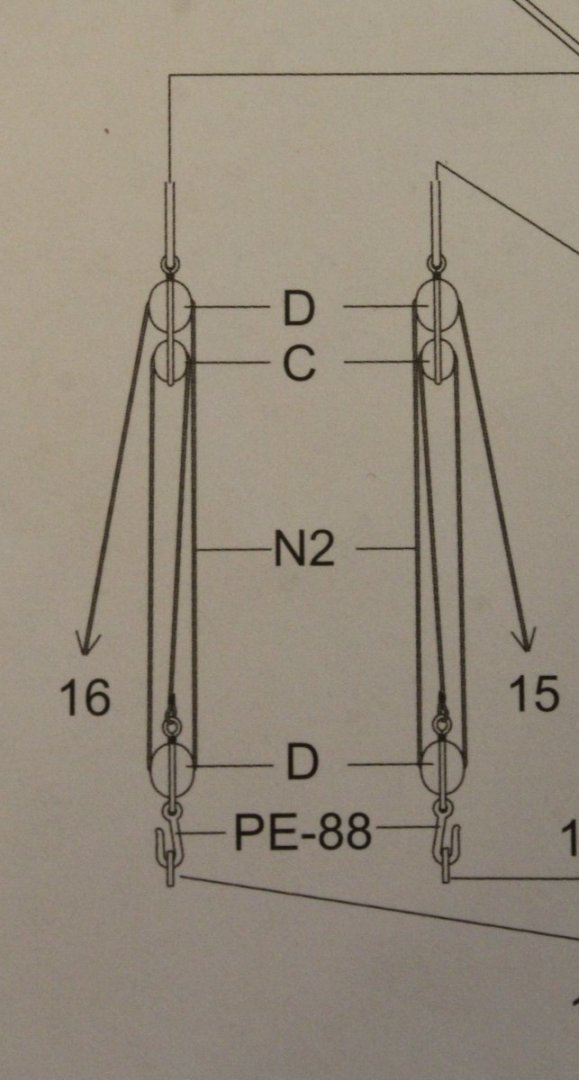
In the ensuing text and associated photos I have detailed the method I have used to make this blocking arrangement.
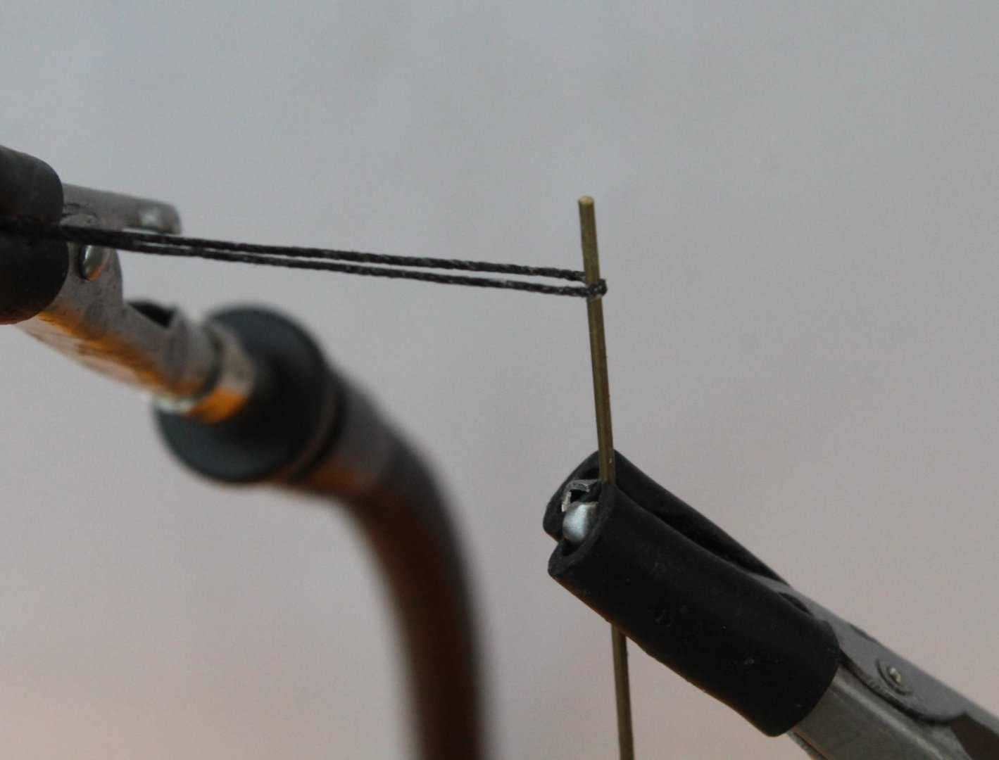
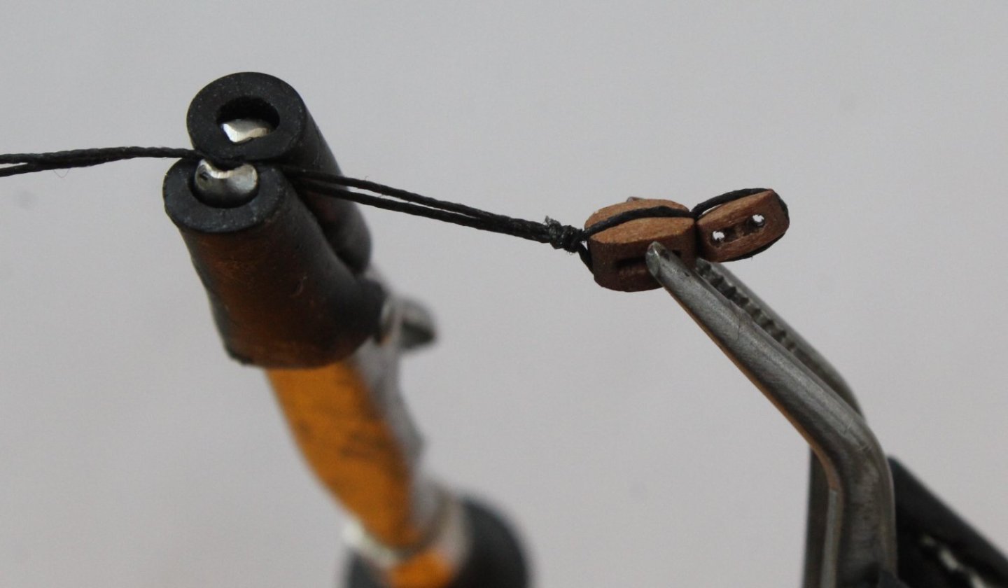
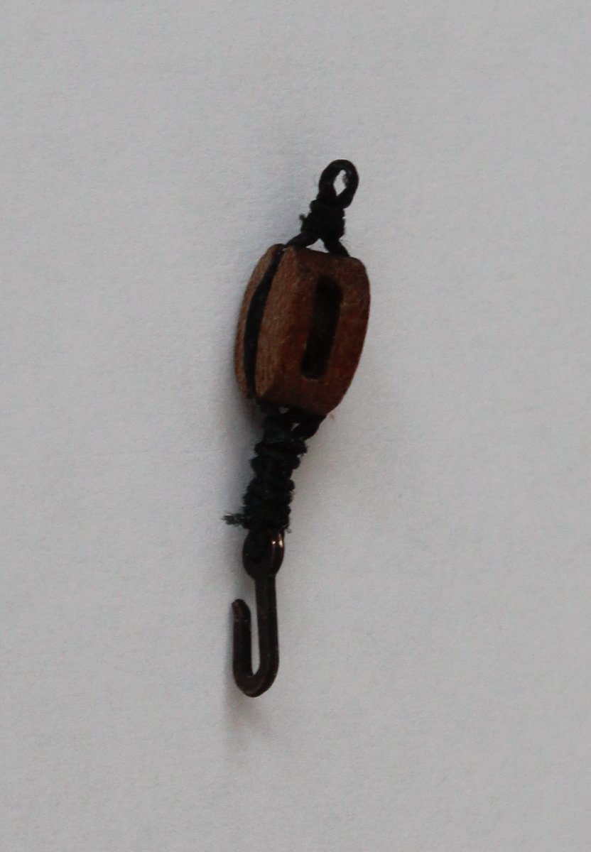
The lower block
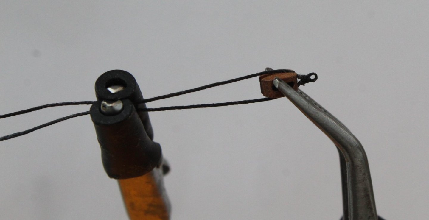
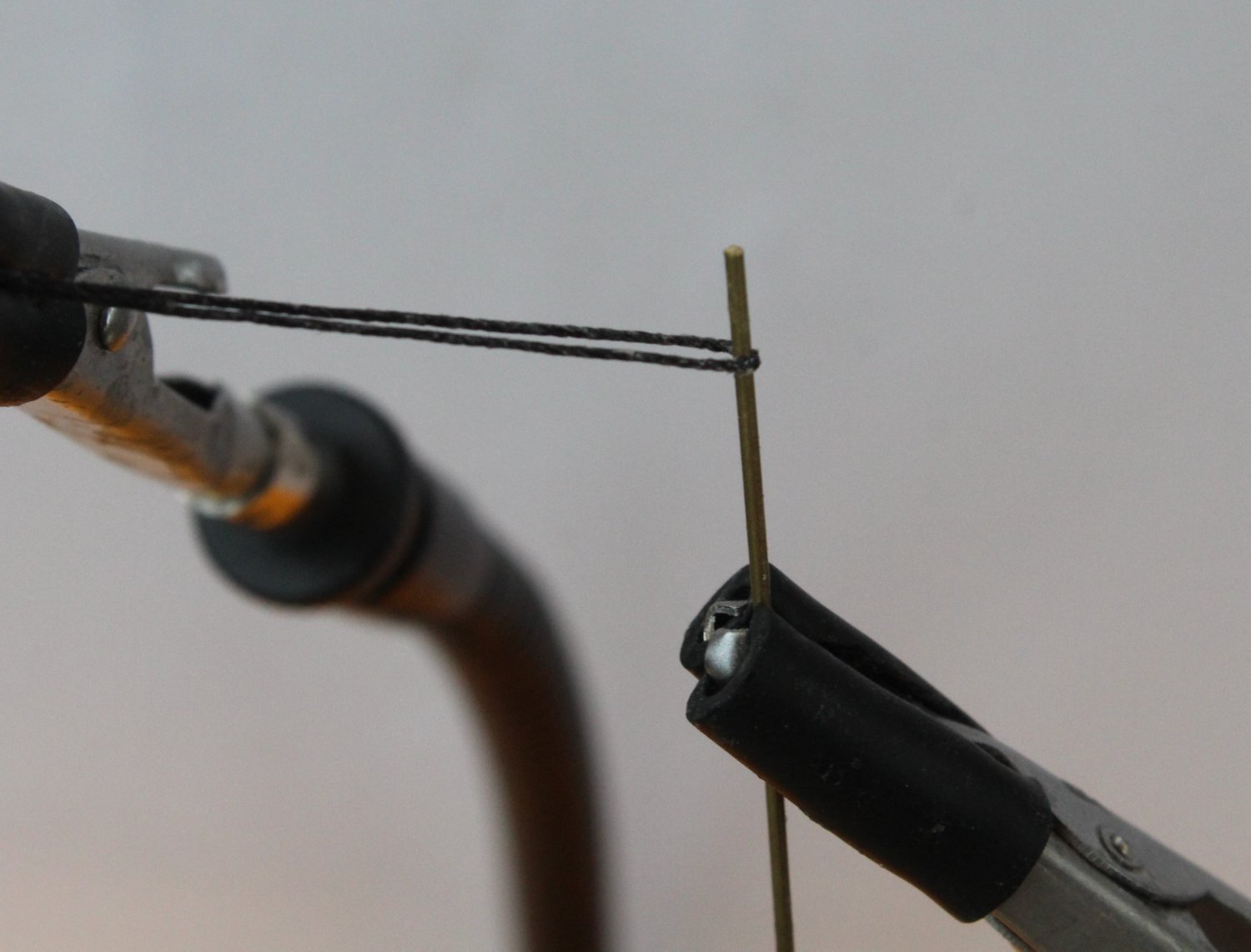
This is a single block with a thimble at the top of the block. A hook is seized to the bottom of the block. To start this process I took a length of 0.5mm black thread and wrapped it around a metal rod which was held in the quad hands, as shown in the photo below.
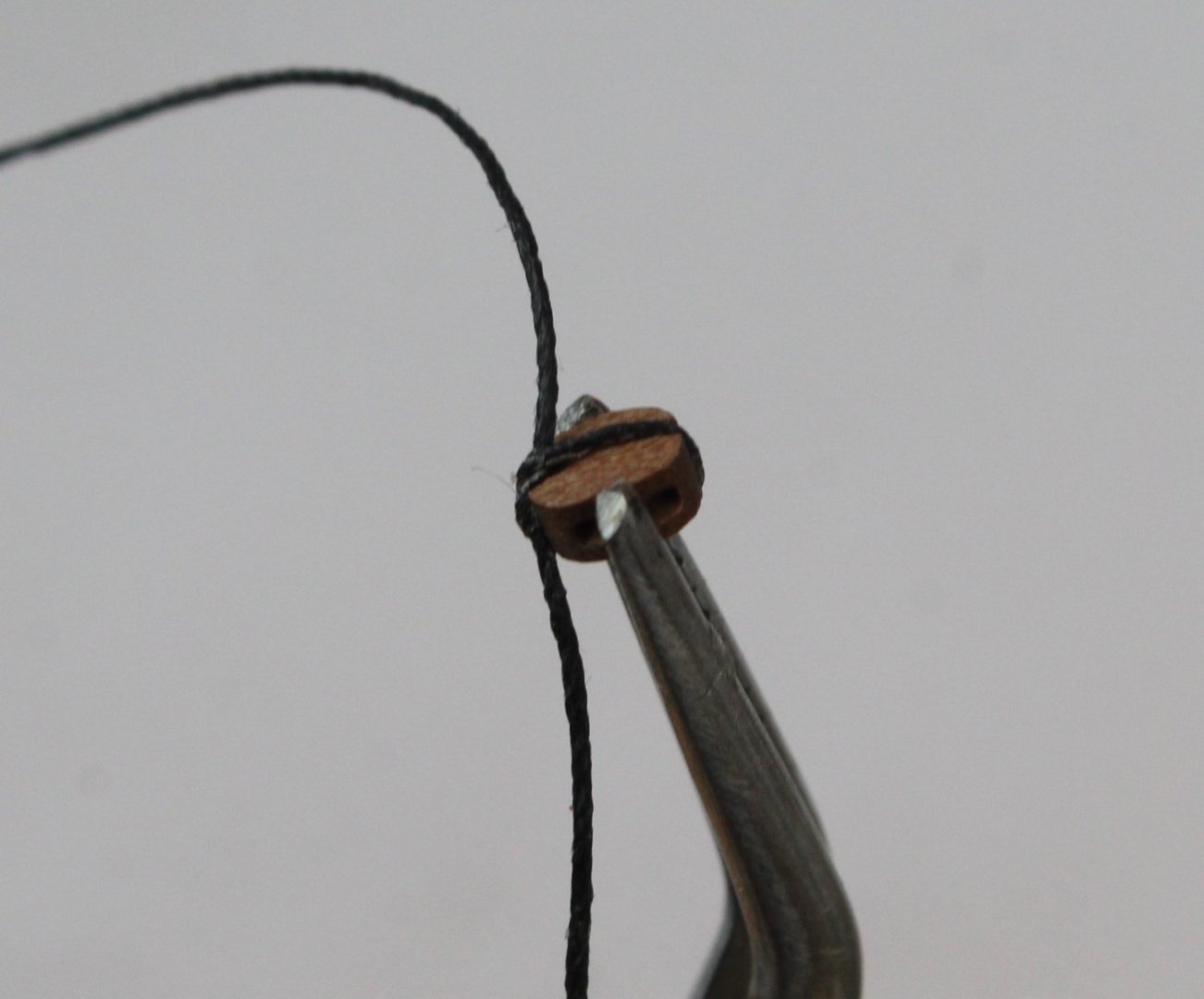
Using some 0.1mm black thread to add the seizing i was able to create the required thimble, as can be seen in the next photo.

The block was then placed in the quad hands and the thread was then added. In the next photo the block is now ready to be seized.
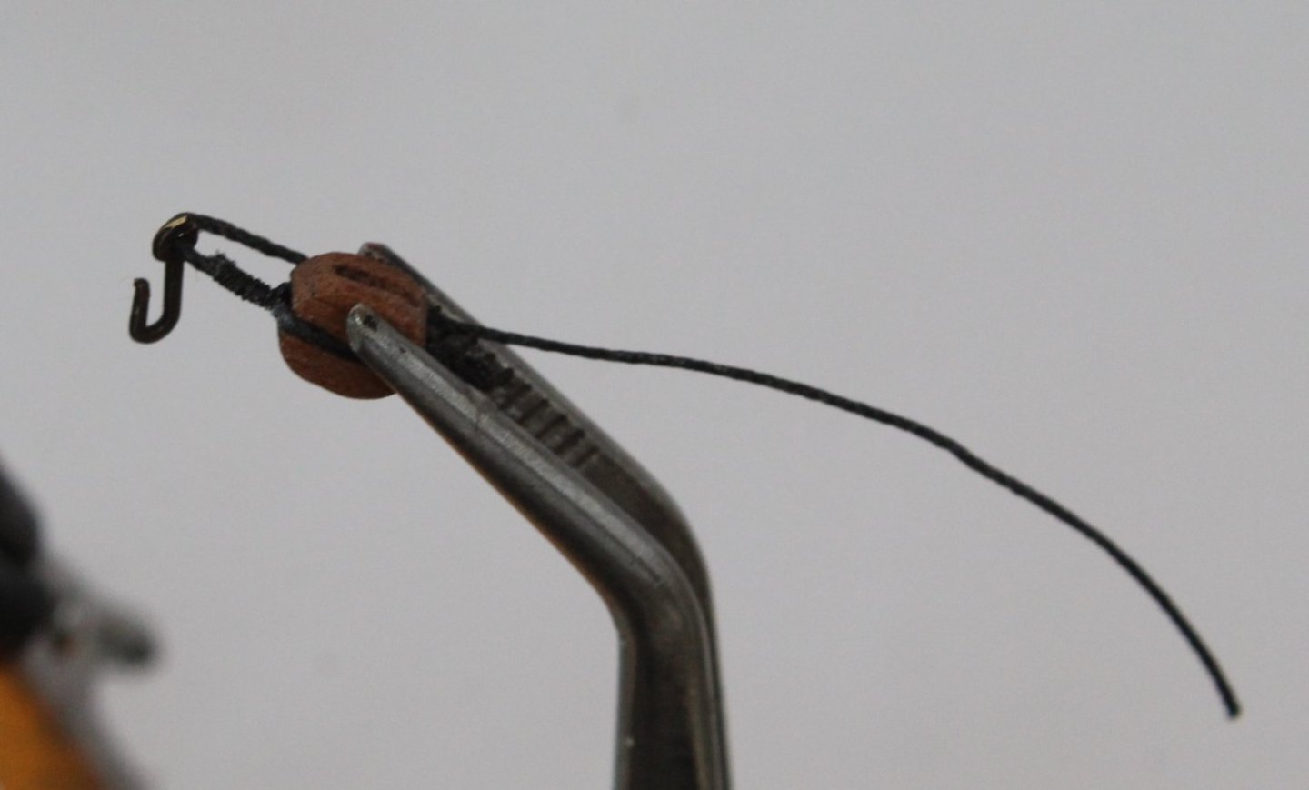
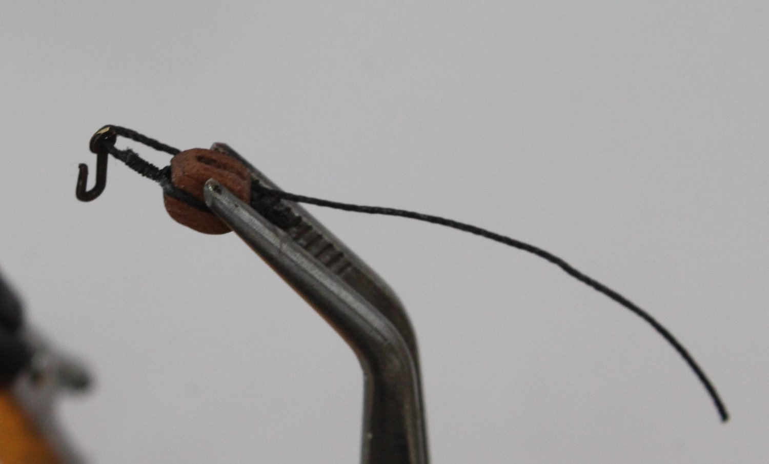
Once the block was seized, one of the thread ends was cut away and the hook was then threaded on the remaining thread end. This is shown on the next photo.
The thread end was then clamped to the side of the block. I have shown this arrangement in the next photo and the hook is now ready to have the seizing applied.
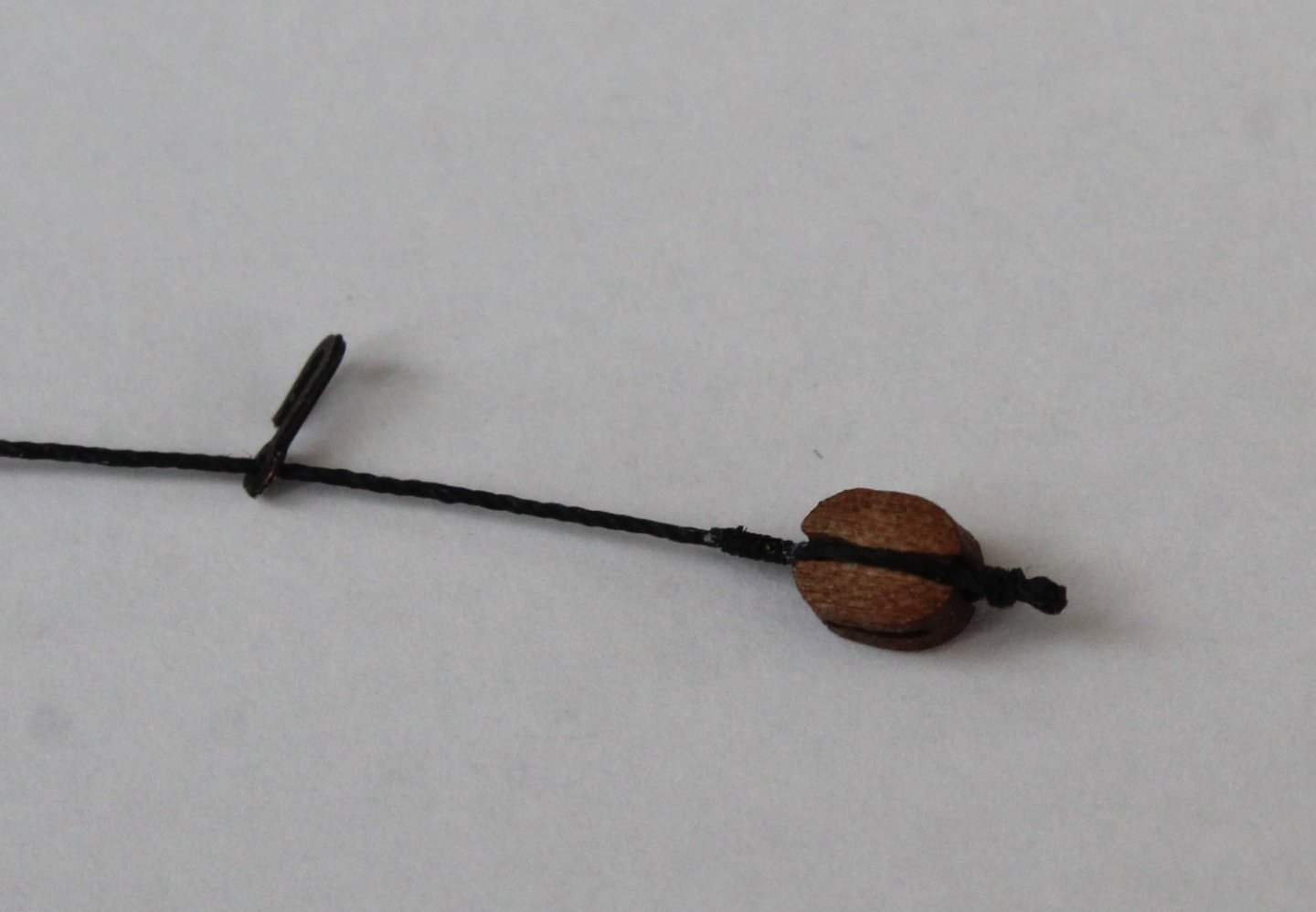
Once the hook has been seized the excess thread can be removed. The next photo shows the completed block.

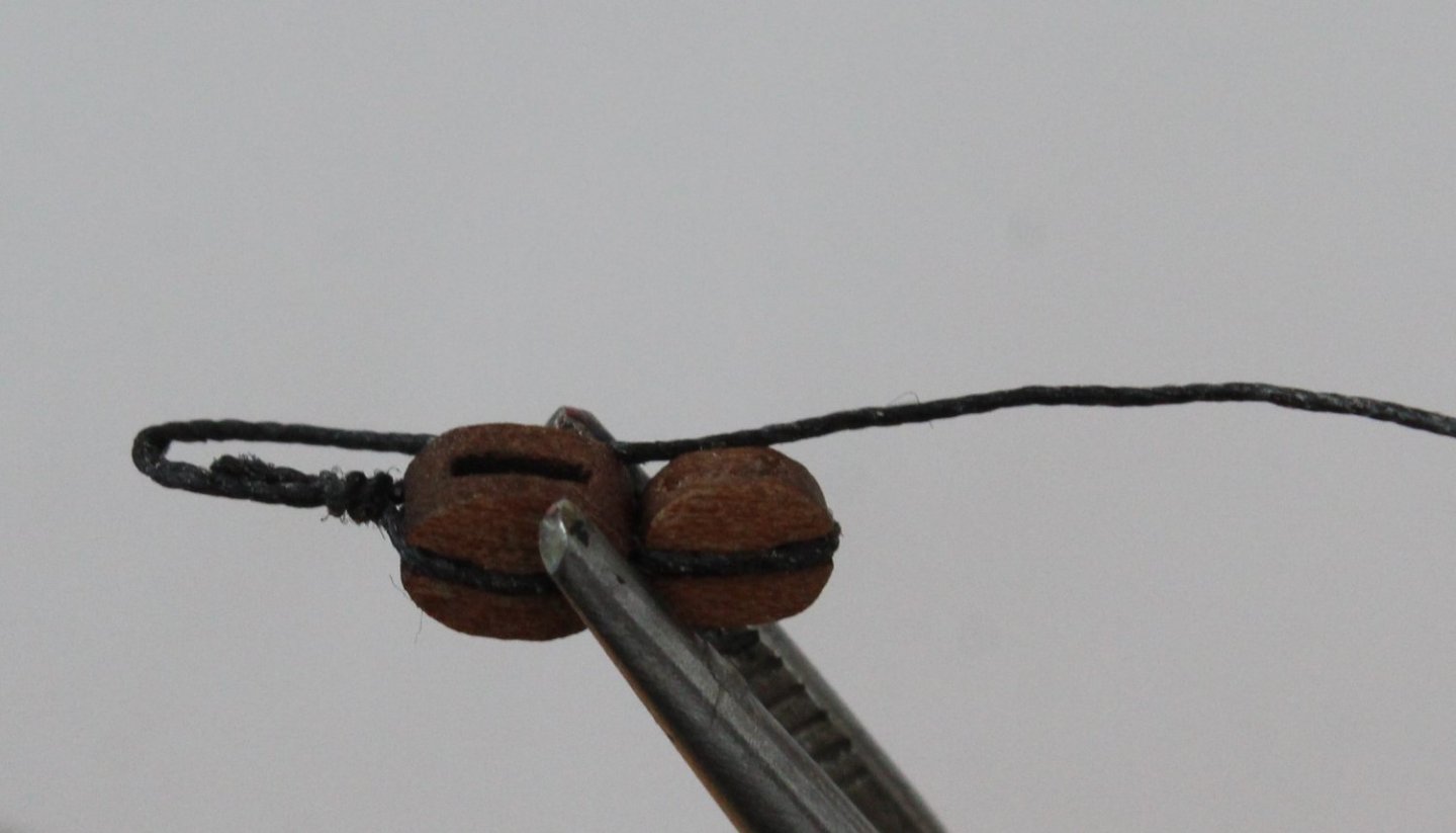
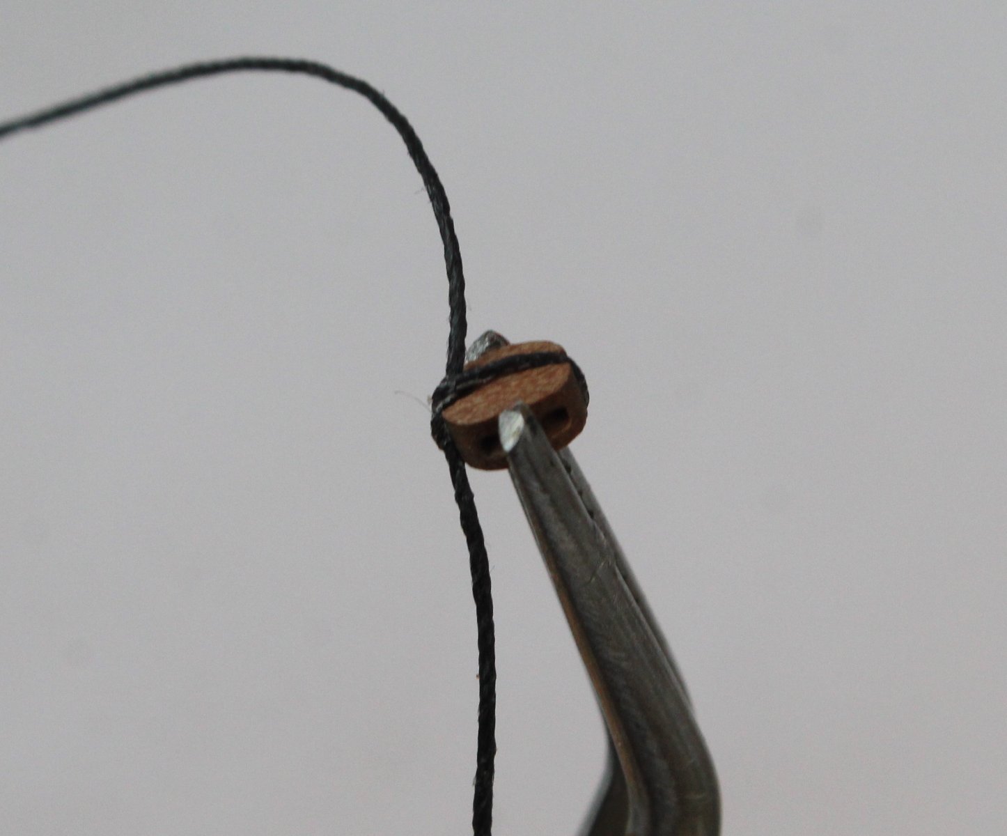
The double block
This is a more complicated arrangement as it consists of two block seized together with a thimble on the top of the larger block.
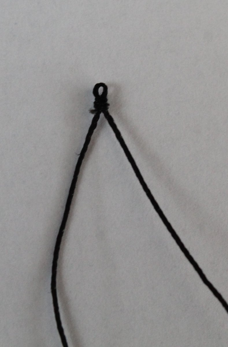
I started with a length of 0.5mm black thread which was secured to the smaller lower black with a simple cross over knot, as can be seen in the next photo
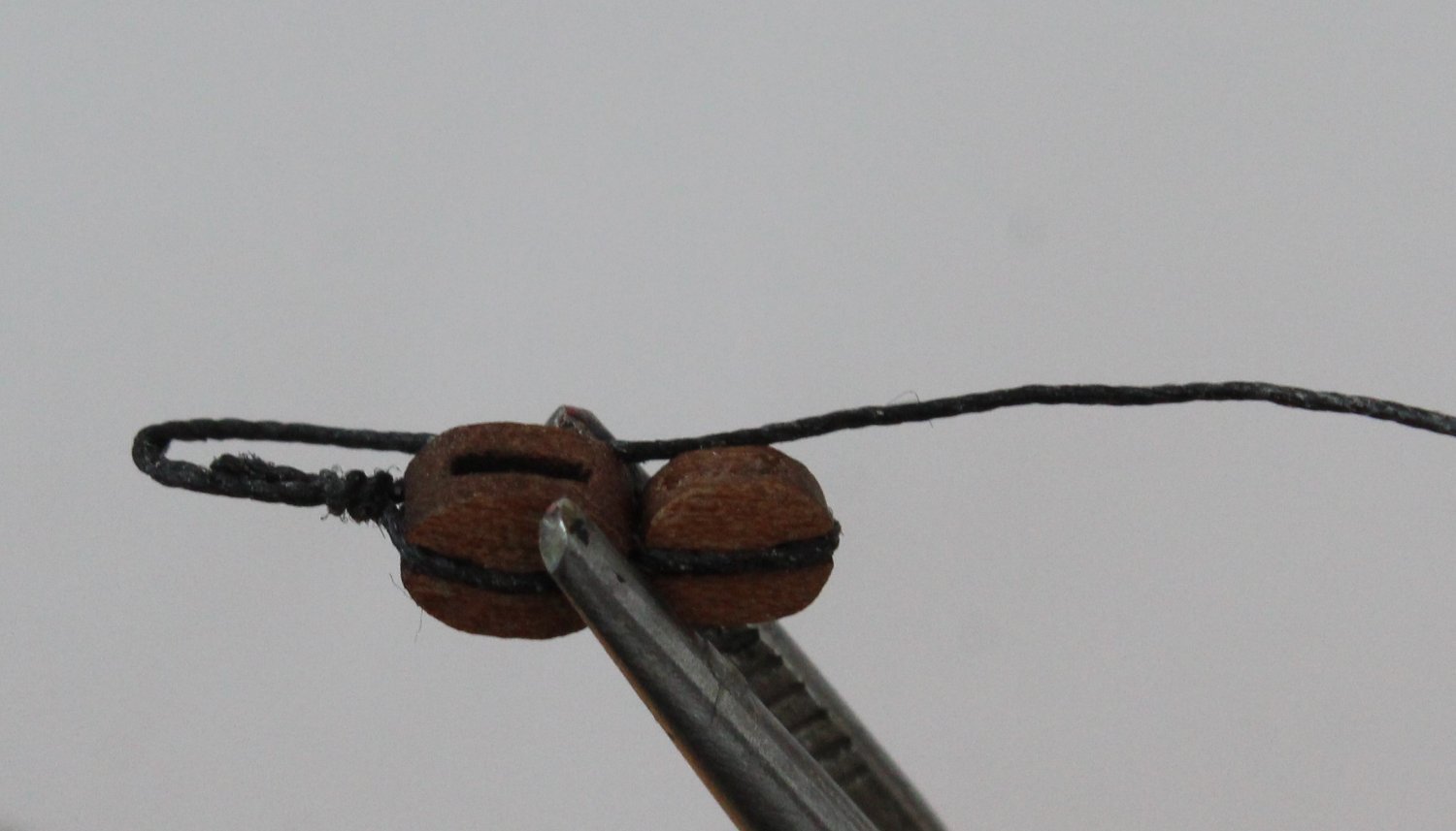
The two blocks are then held in the quad hands and the seizing is added.
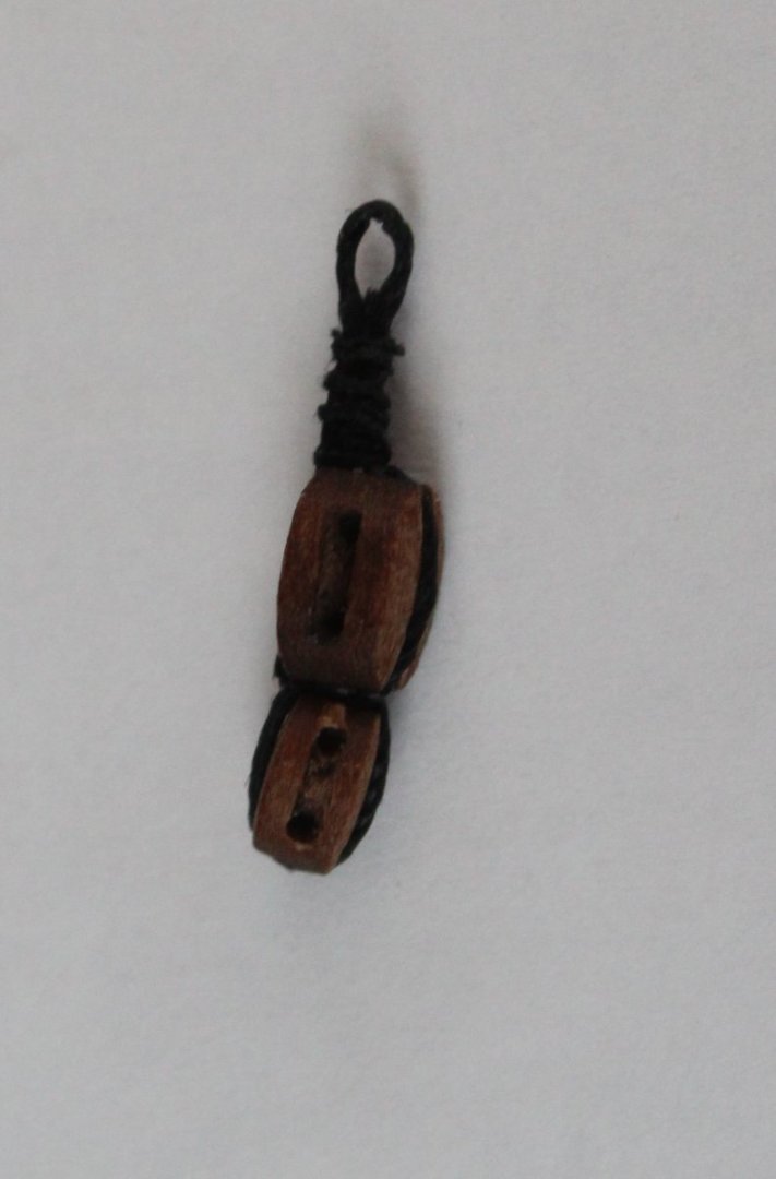
One of the free thread ends was then removed. The thimble is formed by holding the thread to the side of the block, as shown in the next photo.
Once the thimble has been seized the excess thread is removed. The completed double block is shown in the next photo.
The first set of blocks for the topsail stays is now completed. I will now repeat the above process to make three more blocking sets.

- chris watton, AON, schooner and 7 others
-
10
-
Topgallant Shrouds
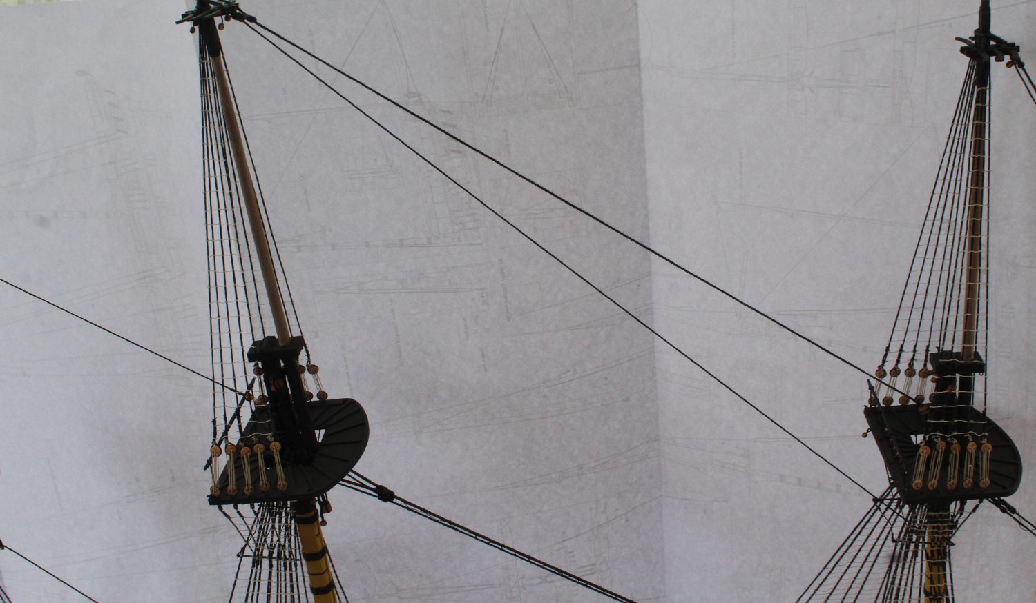
I have now added the shrouds to the fore, main and mizzen topgallant masts.
Fore topgallant mast shrouds
Main topgallant mast shrouds
Mizzen topgallant mast shrouds
The topsail and topgallant stays have also been added but have not been belayed. This will be my next task and there is quite a bit of work required in belaying these stays with the blocking arrangements. I have attached a couple of examples.
- ECK, Knocklouder, allanyed and 7 others
-
10
-
Possibly, not shown on the build plans. I am content with what I have done.
- James H, chris watton, BikerMart and 5 others
-
8
-
13 minutes ago, allanyed said:
Hi Glenn,
Is the last photo the top of the topmast or topgallant mast?
Thanks
Allan
Topsail mast, the topgallant mast will slot in square hole between the stays.
- Theodosius and allanyed
-
2
-
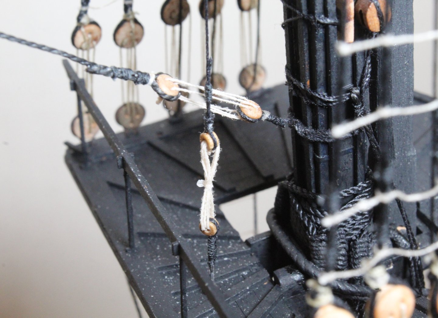
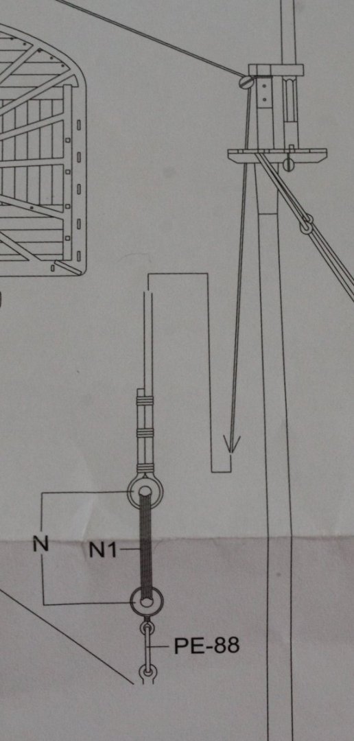
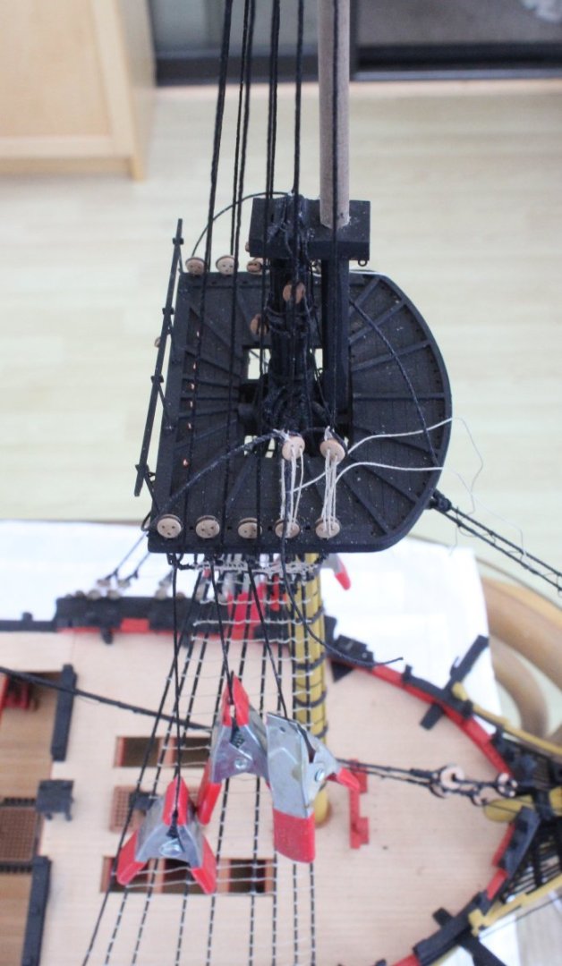
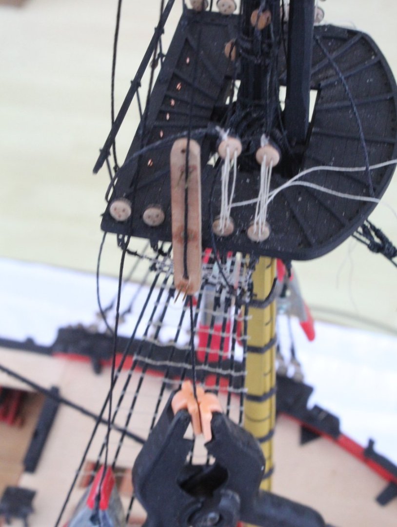
Topgallant Yard Lift Blocks
I spend the last couple of days adding the all the shroud cleats.
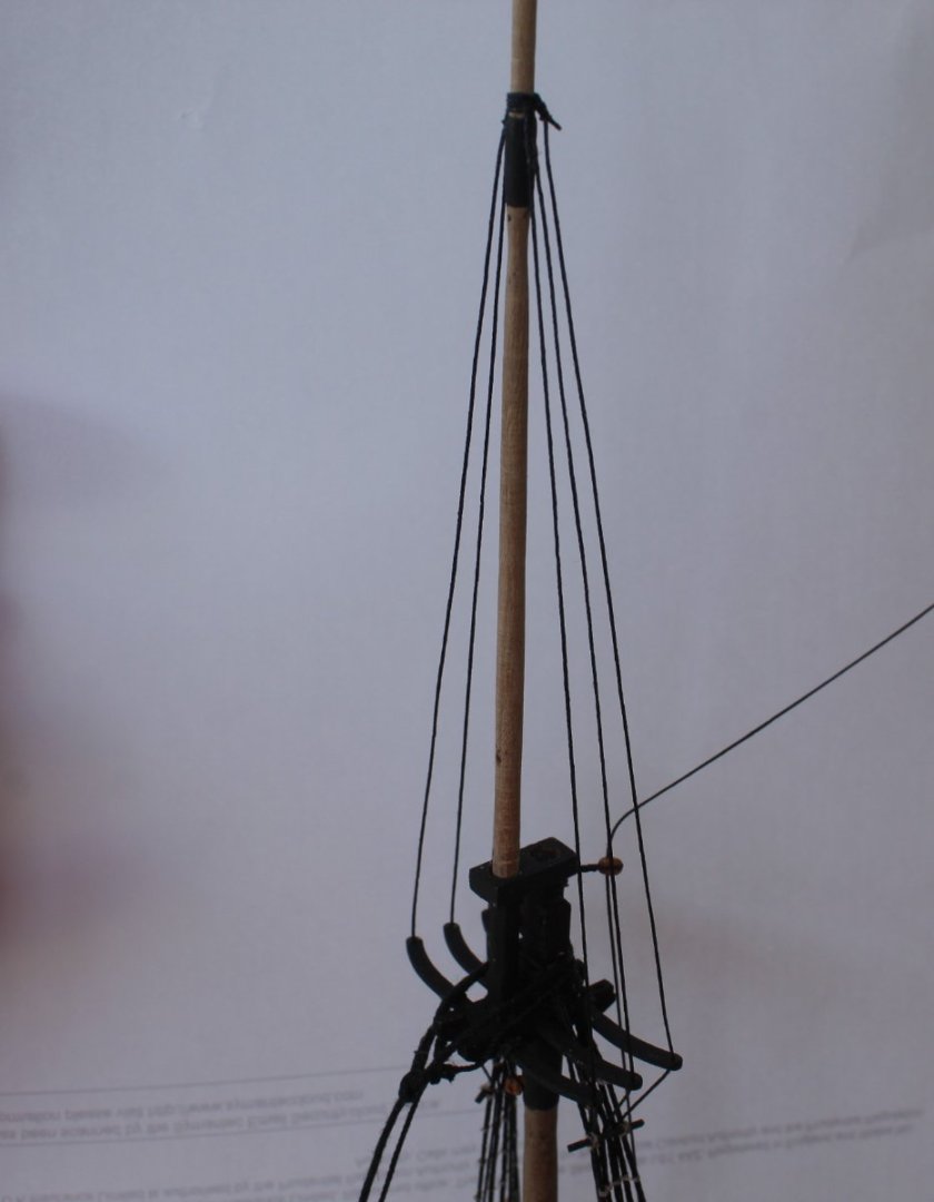
When looking at the plan sheets with regards to the topgallant shrouds I noted that I need to add blocks for the topgallant yard lifts as these are sited between the first and second topsail shrouds. It makes sense to me to fit these before the topgallant shrouds are added.
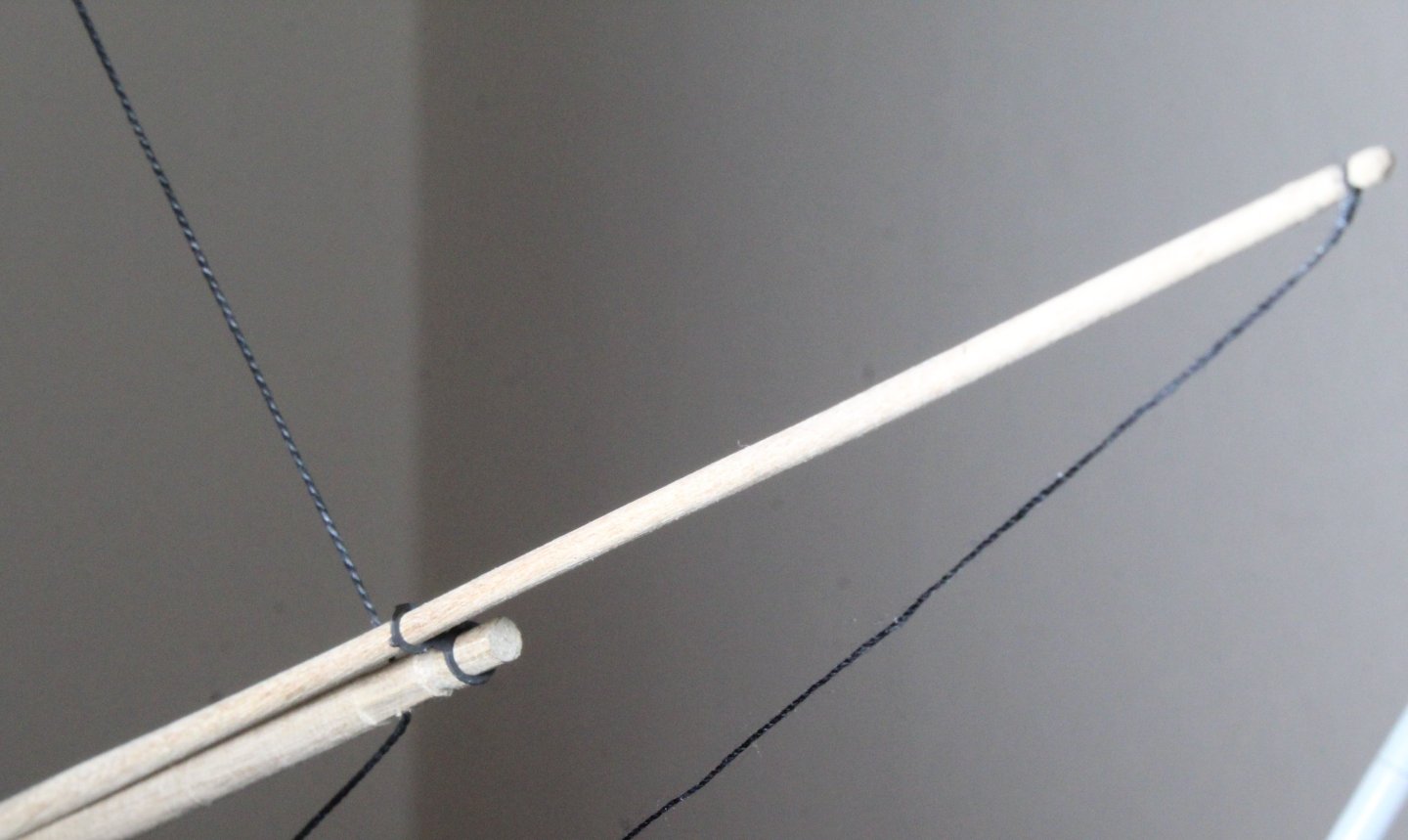
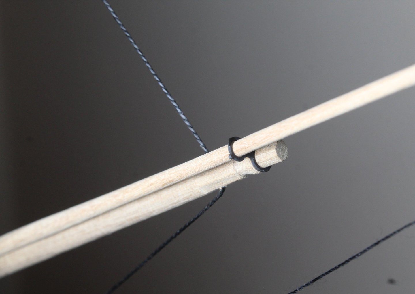
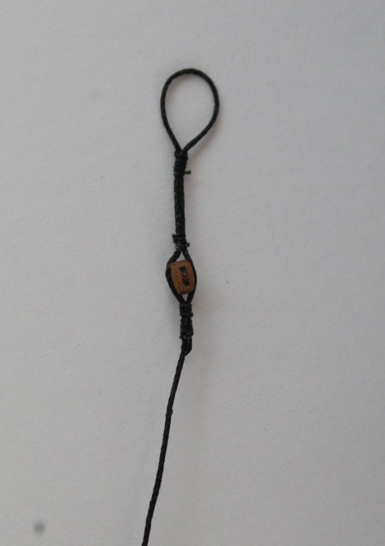
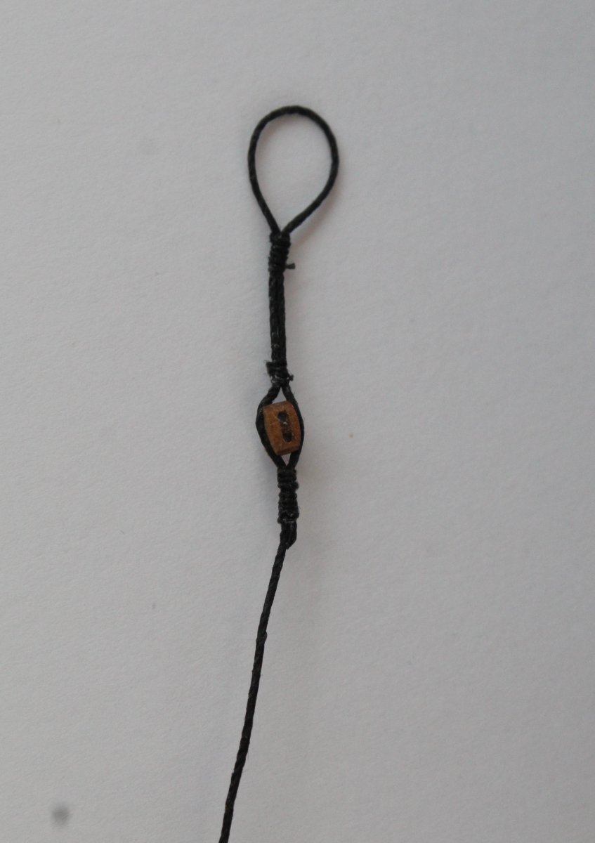
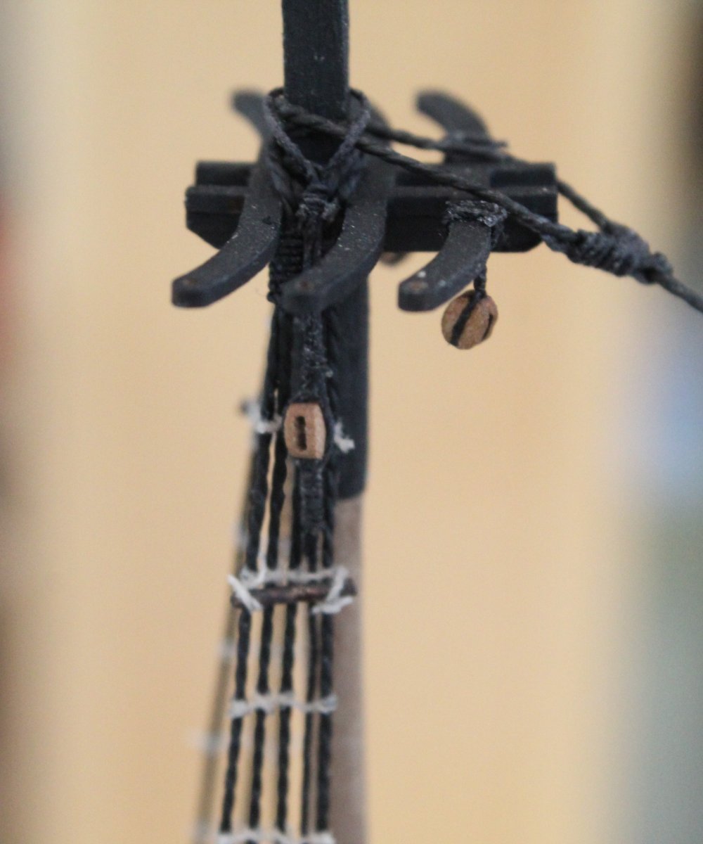
In the first photo below I have shown the arrangement I am using for these blocks. The large loop can be passed over the top of the topsail mast. The block is used for the topgallant lift and the bottom end is then belayed to one of the topsail shroud cleats.
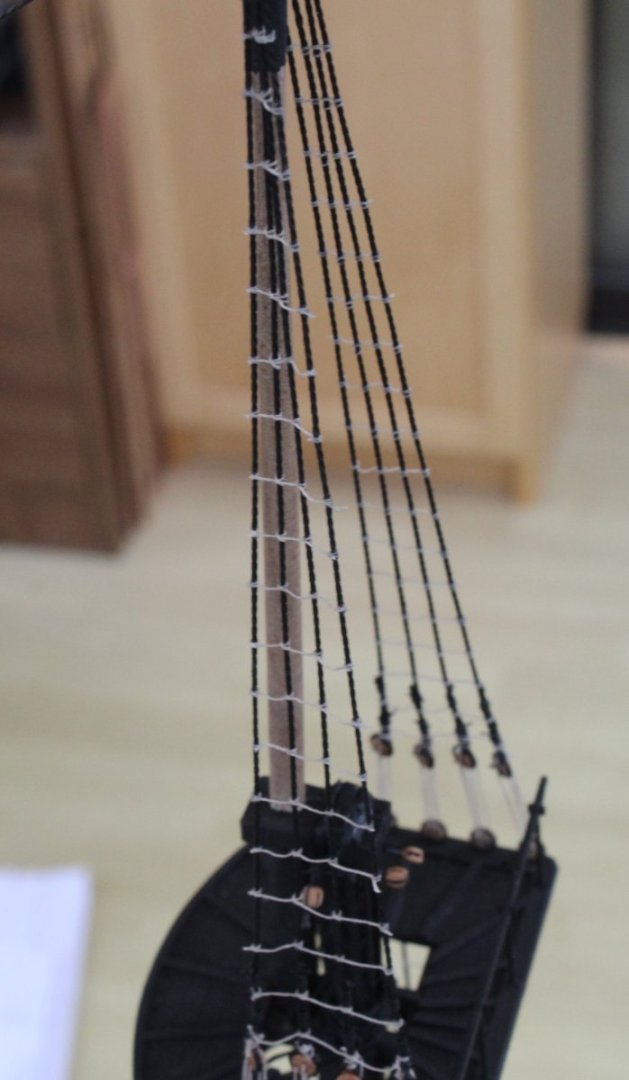
The next photo shows the arrangement is place.

- chris watton, Theodosius, RossR and 11 others
-
14
-
2 minutes ago, Thukydides said:
That must be a relief. I only had a few to do on Alert and I did not enjoy even the little I had to do.
It is looking great, she is very imposing.
Thanks, I quite enjoy adding the ratlines, the repetitive nature can be therapeutic. It is a big relief once it is done however.
- RossR, Mr Whippy, Thukydides and 3 others
-
6
-
-
Mizzen Topsail Shrouds and Topsail Stays
This morning I added the final ratline when I completed the mizzen topsail shrouds.
Before moving on to adding the topgallant masts and associated shrouds I ran in the threads required for the topsail mast stays.
Starting with the mizzen topsail mast stay
 The main topsail stay and preventor have been run in, but I have not belayed to the deck as yet.
The fore topsail stay and preventor have been run in, but I have not belayed them to the deck as yet.

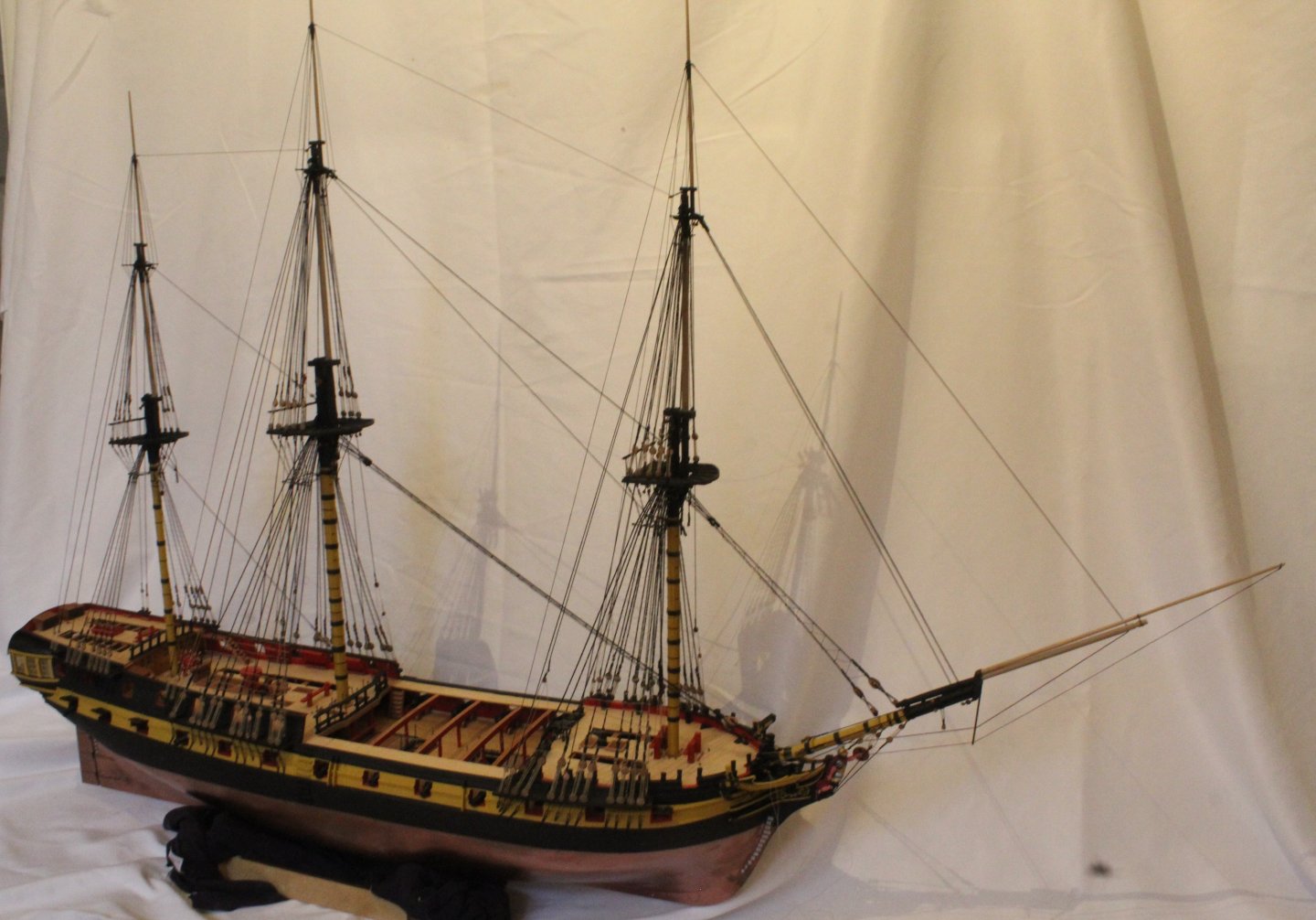
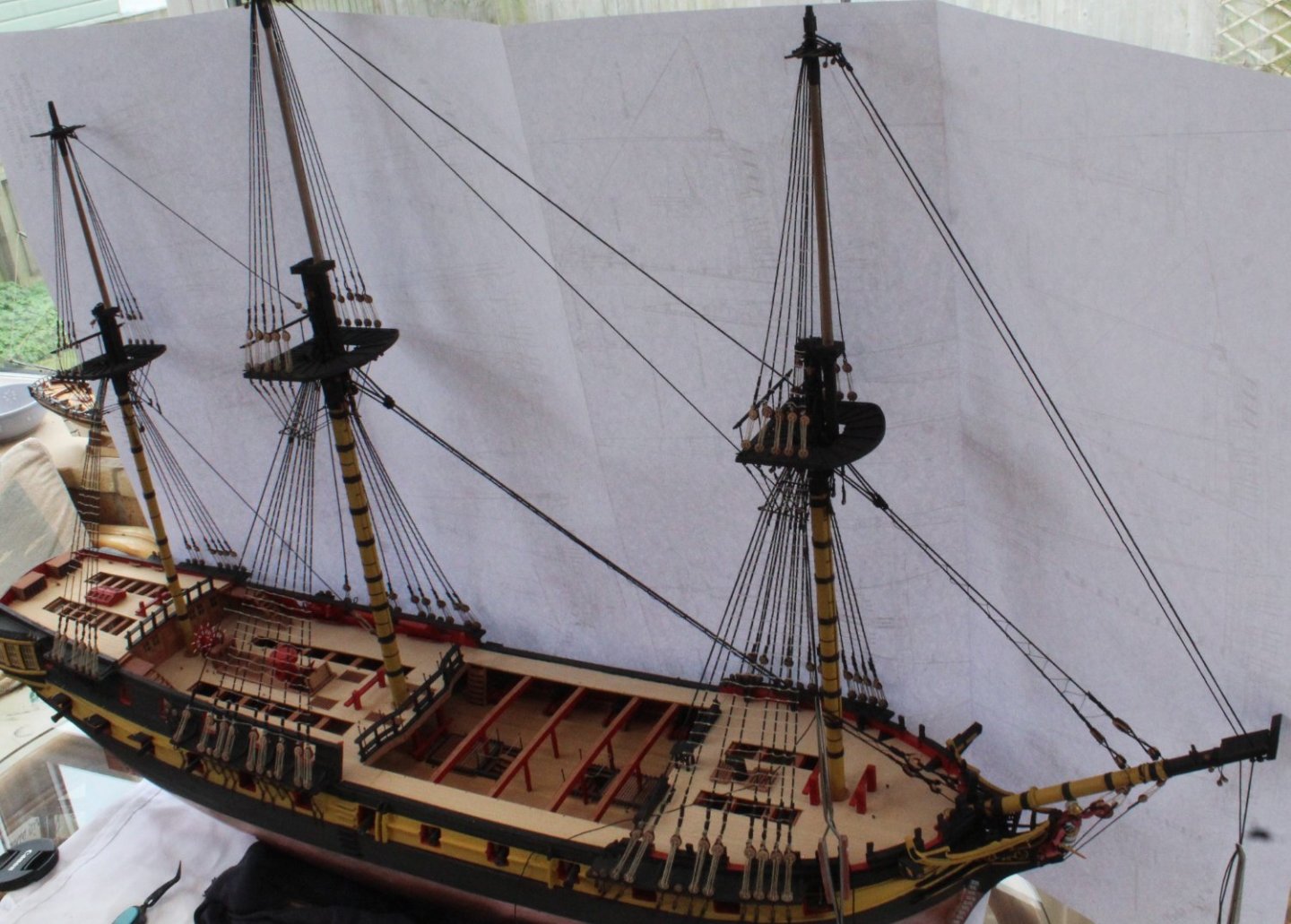
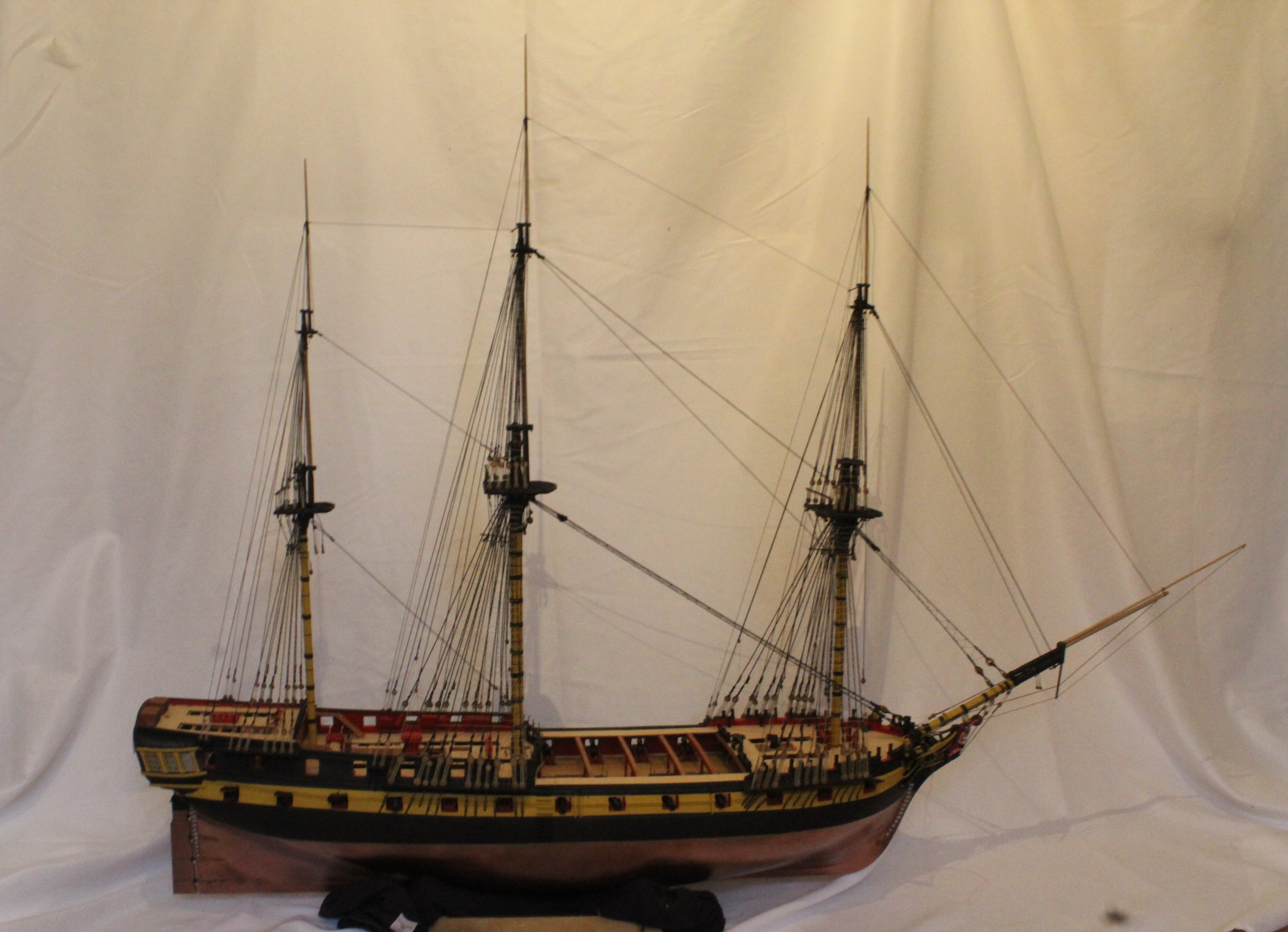
Current build status

-
-
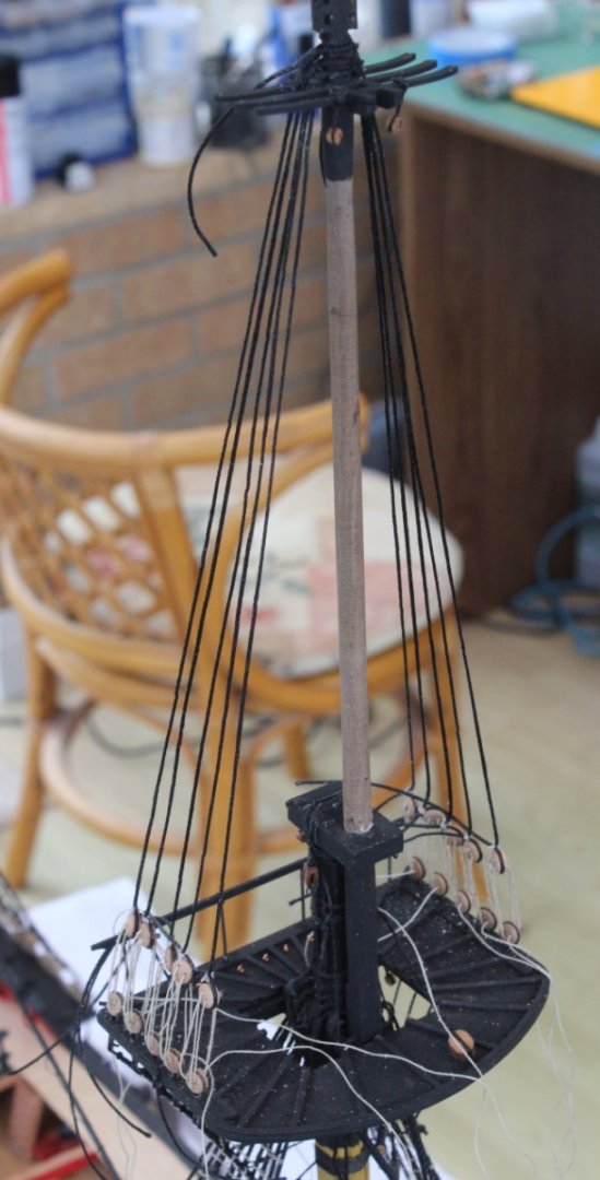
Main Topsail Mast Shrouds
Despite suffering with a bad case of manflu I have bravely continued with working on the Indy build. Over the last couple of days I added the main topsail mast shrouds and ratlines. I used the same method as detailed in my fore mast topsail post(s) and I am reasonably happy with the end result.
Next up will be adding the shrouds and ratlines to the mizzen topsail mast. I will have very limited time in the shipyard over the next few days due to grandparenting duties.

- KurtH, Theodosius, wvdhee and 13 others
-
16
-
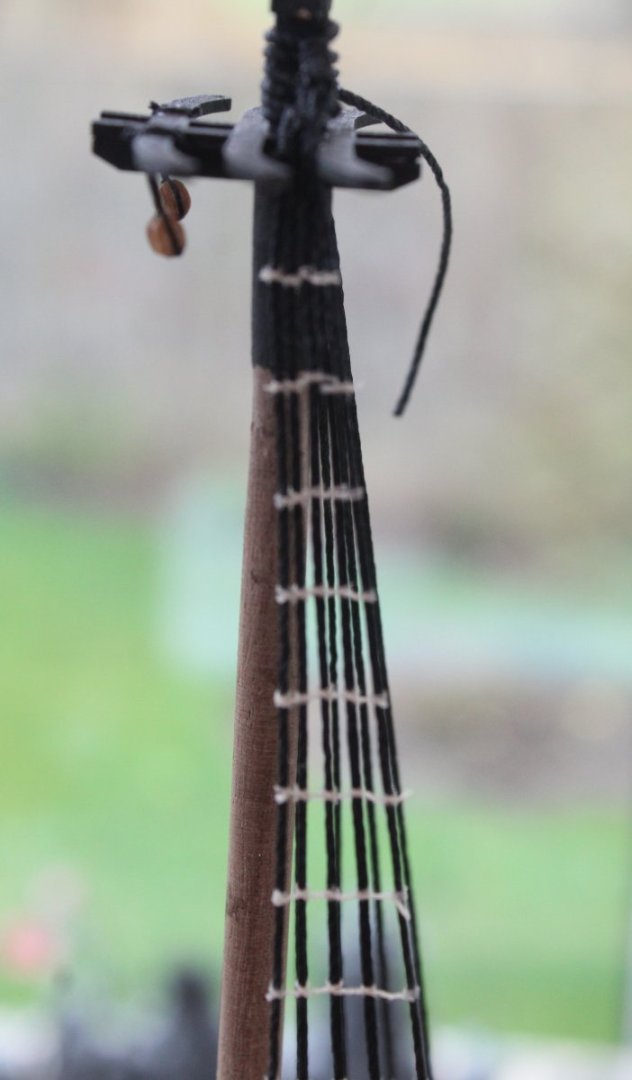
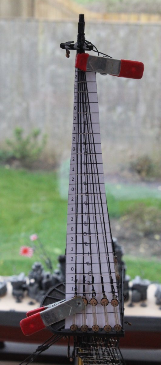
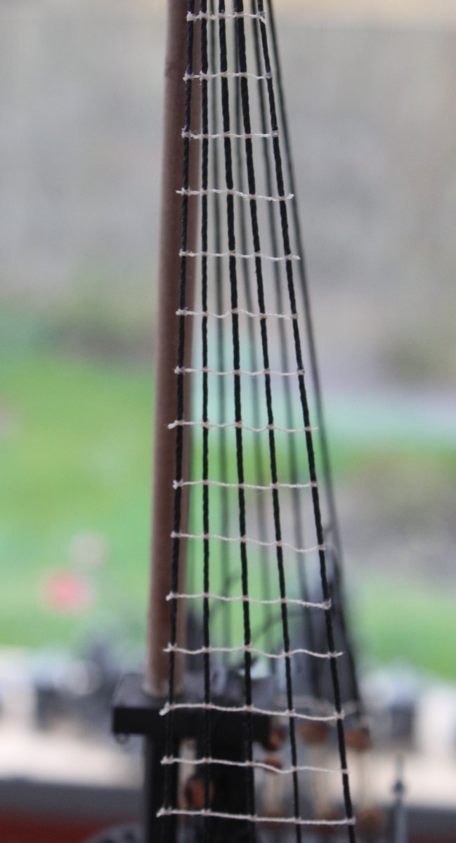
Fore Topsail Mast Ratlines
I am now in the process of adding the ratlines to the fore topsail mast. The first task was to make a template and then clamp in place. In the photo below I have already added a few ratlines. As explained in previous posts I prefer to add every 5th ratline first, as indicated by the 0's on the template. I then add all the 1's before completing the task by adding all the 2's

It took me a couple of hours to complete one side. A couple of the deadeye seizing's could have been done better (i.e. the middle and right hand end ones) but I can live with how they look which is all that matters. Work is now progressing to complete adding the ratlines to the other side.


-
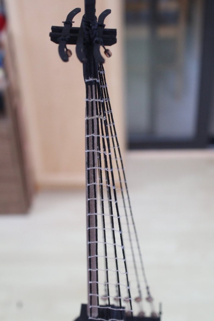
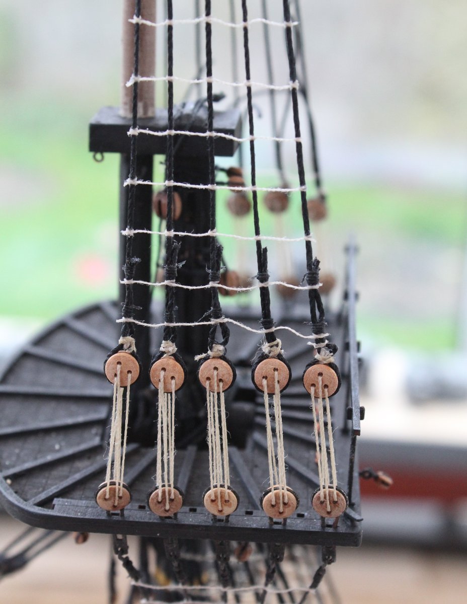
Fore Topsail Shrouds
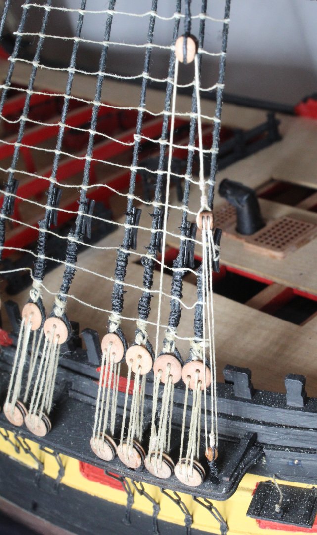
I am currently working on installing the shrouds for the fore, main and mizzen topsail masts.
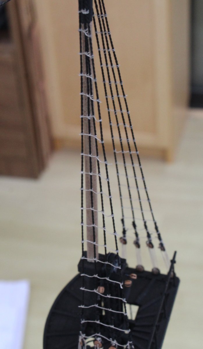
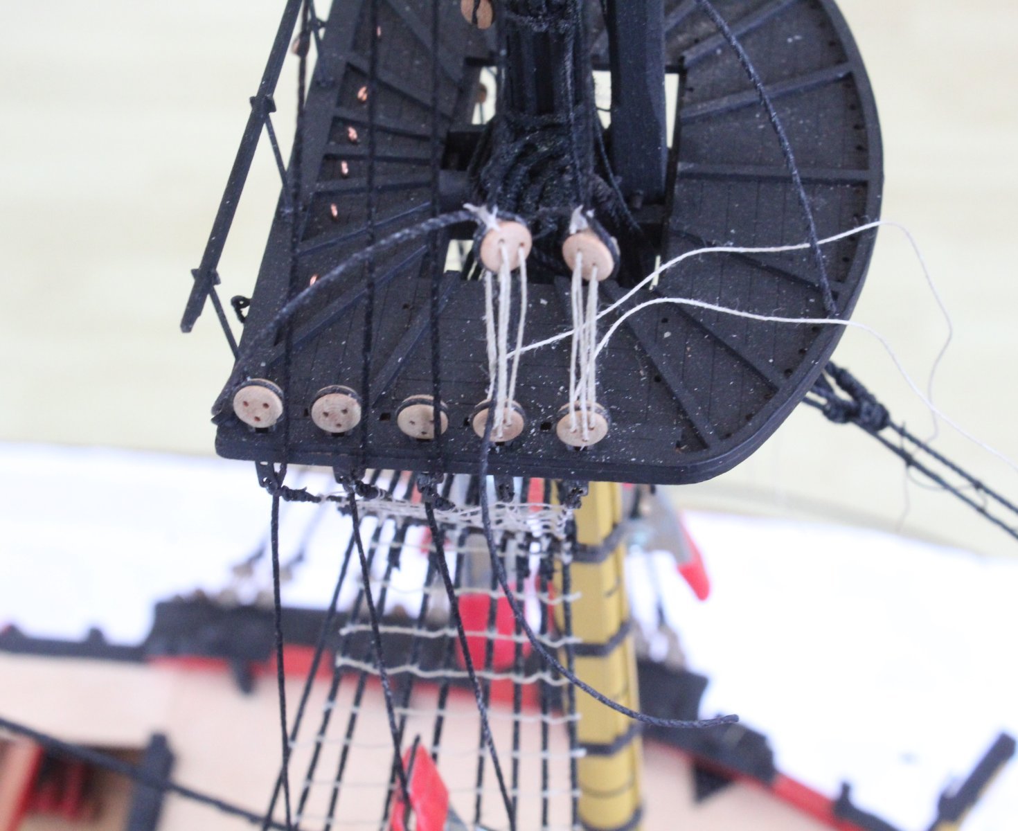
I have added the shrouds to the fore topsail mast, and the lanyards are now ready to be tied off, as can be seen in the photo below.
I started the process by making all the shroud pairs for all three topsail masts. The shrouds were run through some beeswax which was then melted using a hairdryer and were then left hanging with a slight weight to help get rid of all the kinks.

It will then a case of adding the shrouds to each of the topsail masts and adding the deadeyes.
Starting with the fore topsail mast all the shrouds were added. As then were run in I used some clamps to keep them in the approx positions.
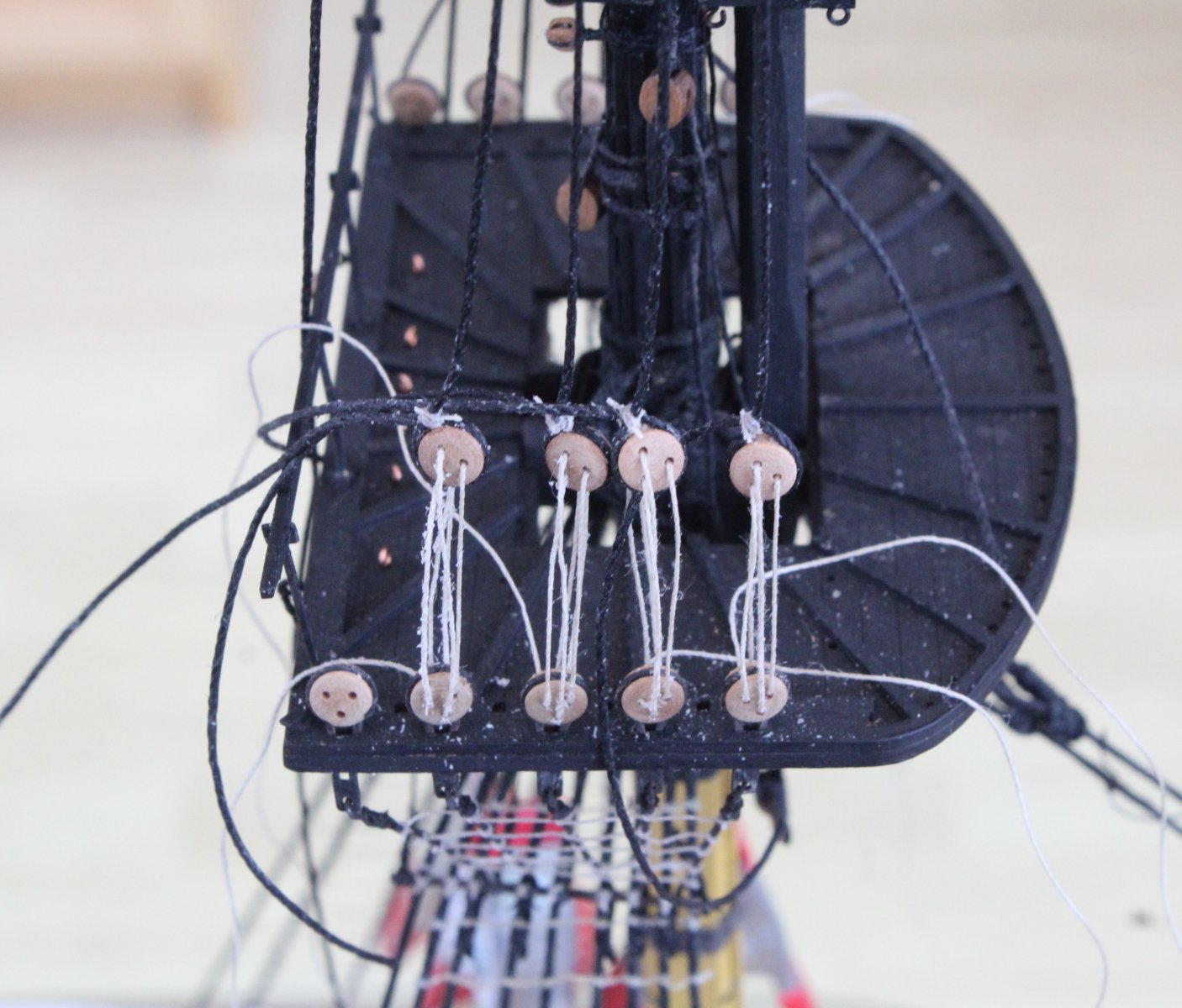
The deadeyes have been added to the first shroud pair and the lanyards threaded in the next couple of photos.

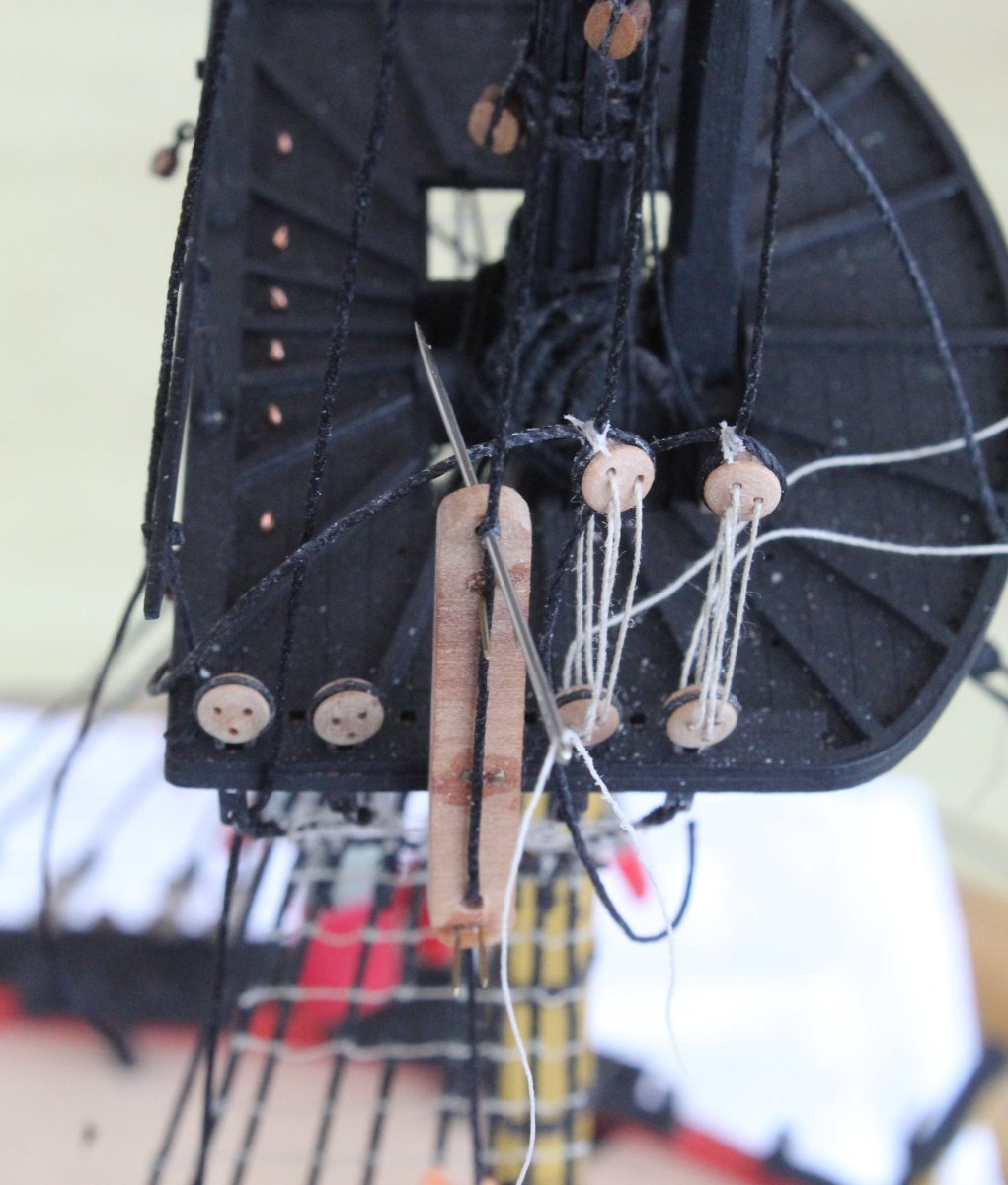
I am using my tried and tested method to adding the deadeyes. The jig prongs are inserted into the platform deadeyes. The shroud is then feed down through the top guides and through the bottom hole. A clamp is used to apply some tension to the shroud.
Next a needle with some seizing thread is passed through the top hole in the jig. This should ensure that each shroud deadeye is set to the same position above the platform deadeye once the lanyards have been added.

It is then an easy job to make the loop the loop. A deadeye can then be placed in the shroud and the free end is then be pulled which closes the loop around the deadeye. As the lanyards are been run in I am pleased that the shroud deadeyes seem to be nice and level with each other. I will need to make the final adjustments when the lanyards are tied off.


-
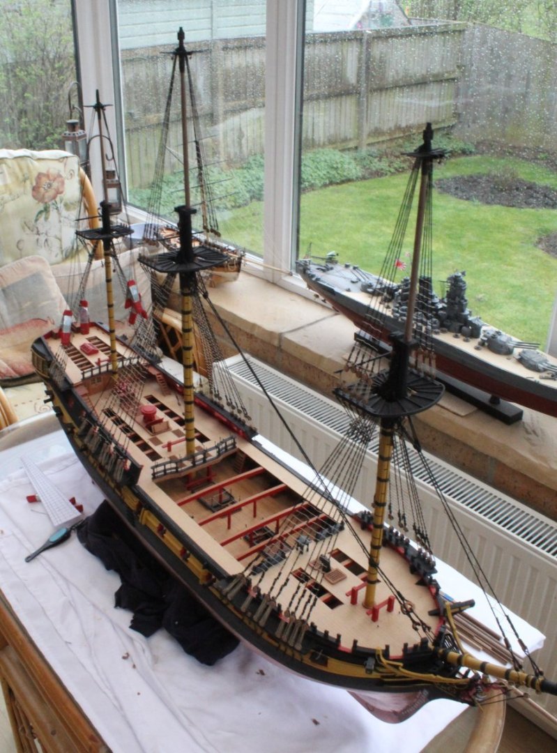
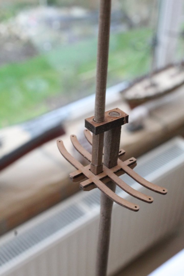
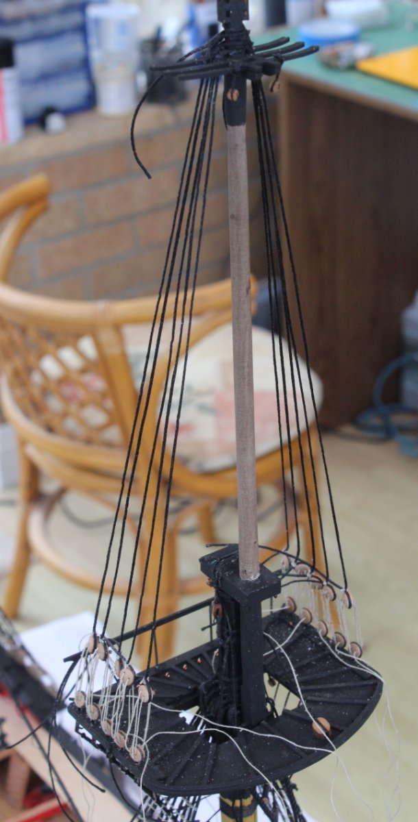
Mast Shaping Completed
This morning I completed the shaping for the fore topsail and fore topgallant masts. These fore mast sections were then successfully test fitted on the Indy.
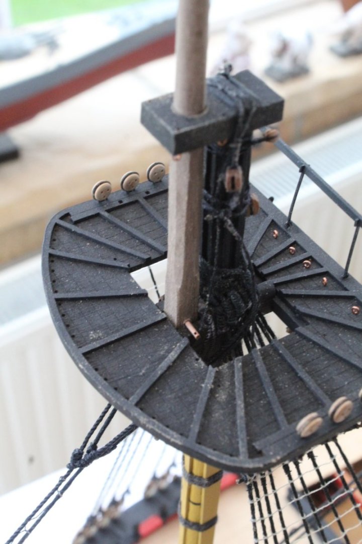
When looking at the next photo I do need make a minor adjustment to where the foretopgallant mast sits within the end cap as the hole for the FID is currently below the platform and cannot be fitted.
The next task will be to paint and add the blocks to all these mast sections (fore, main and mizzen). Once that is done the topsail masts will be added to the Indy so the shrouds and ratlines can be added.
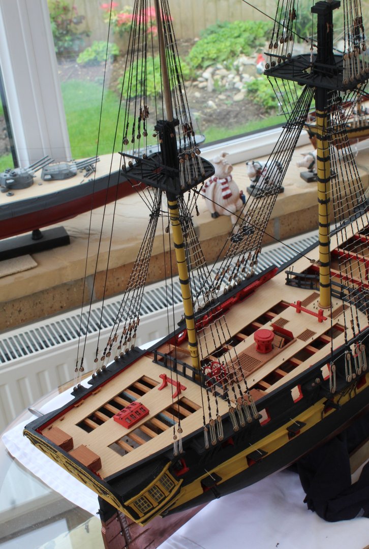
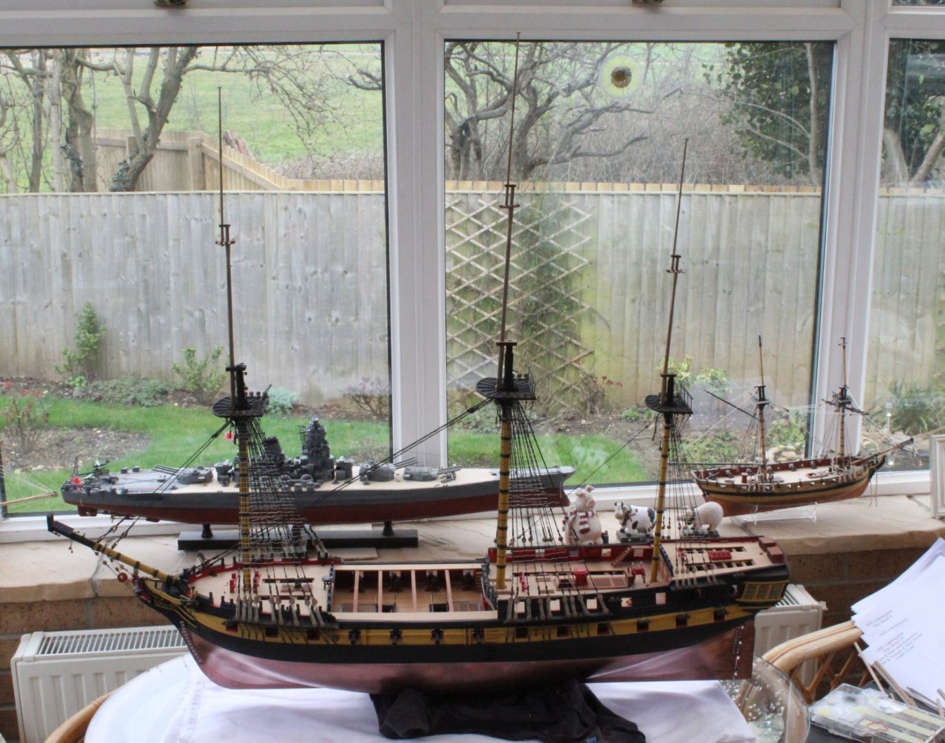
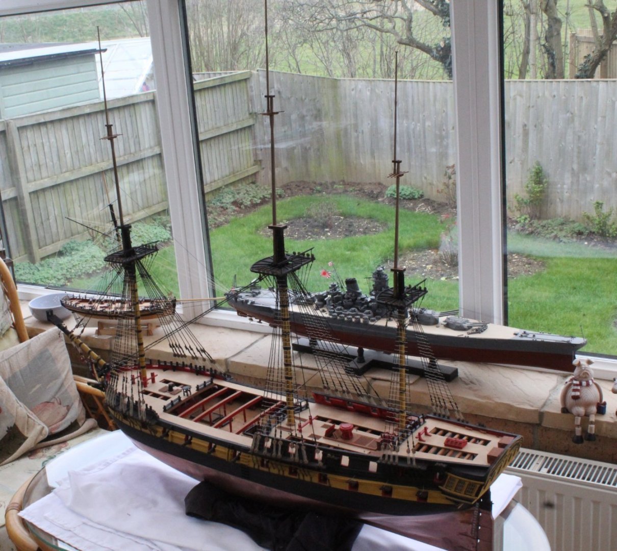
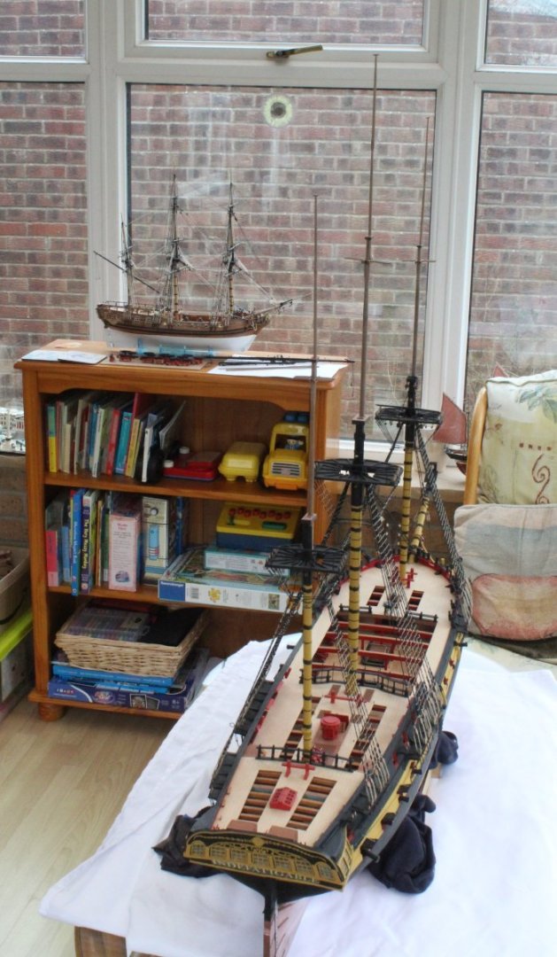
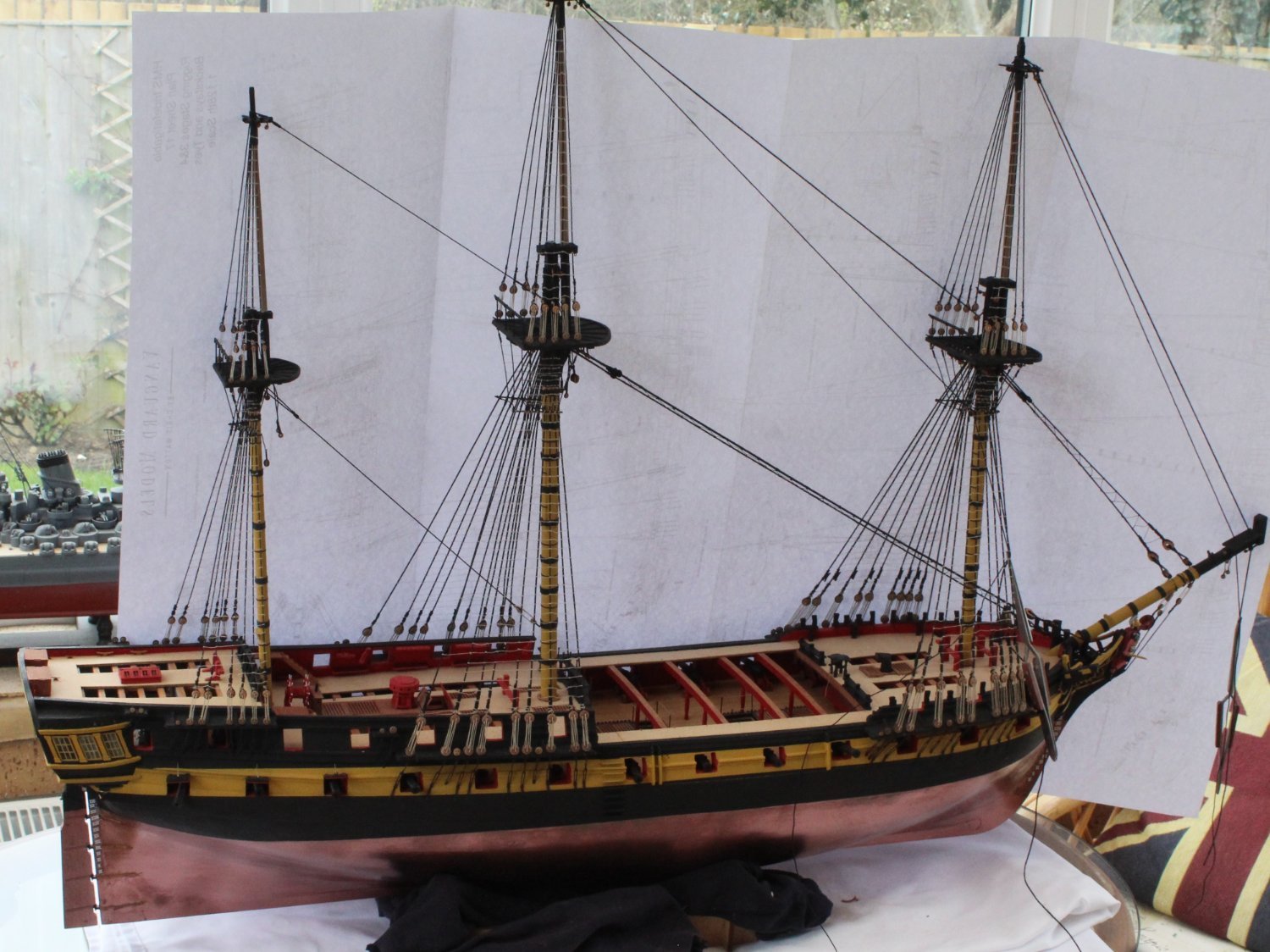
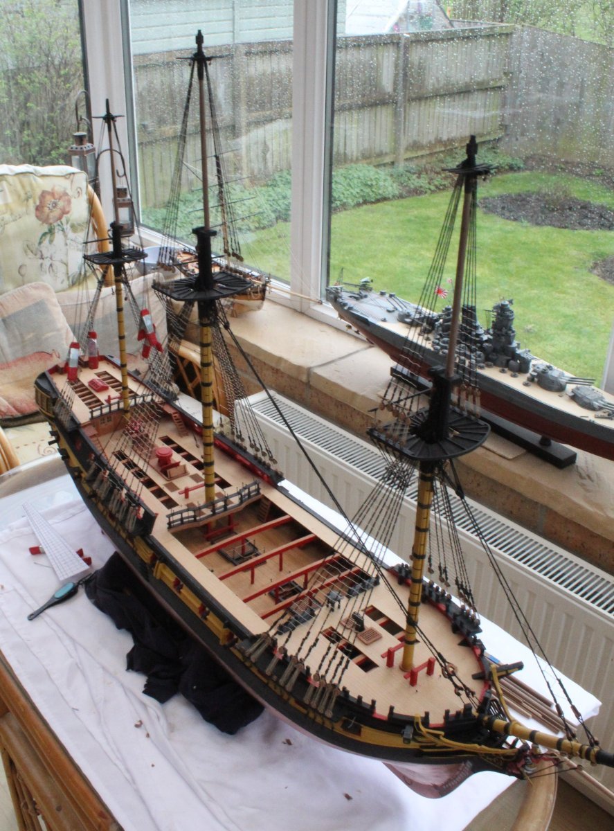
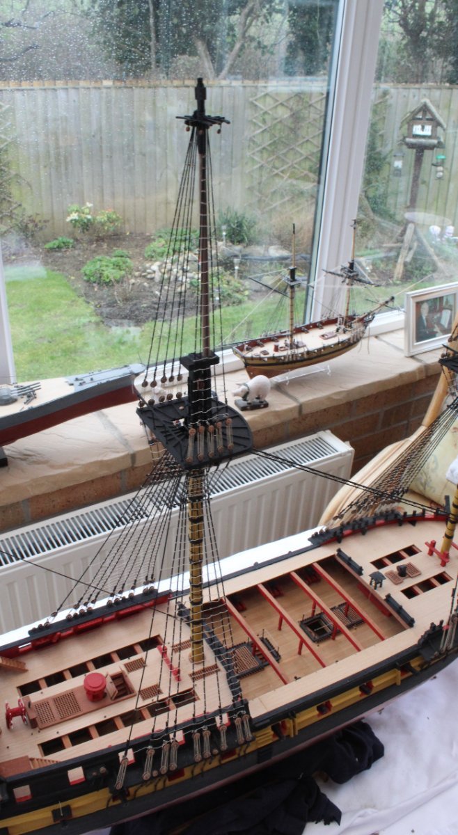
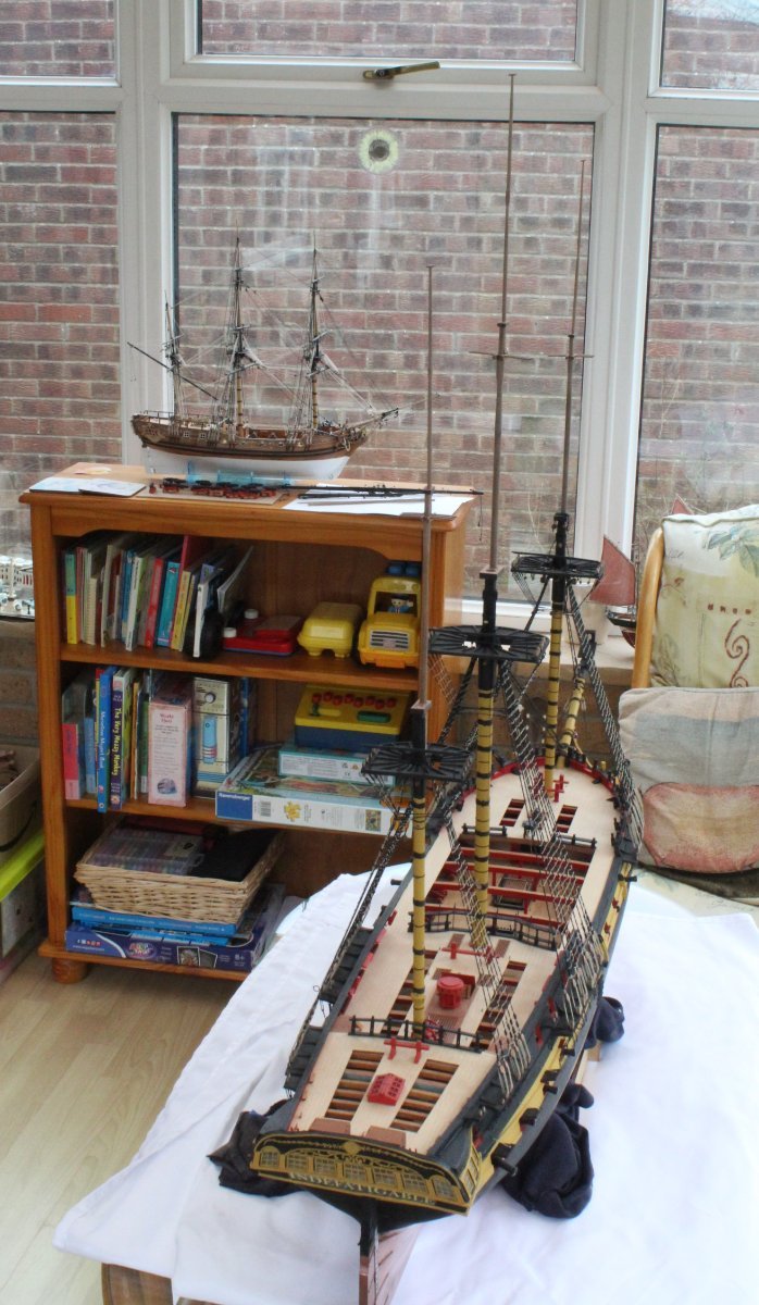
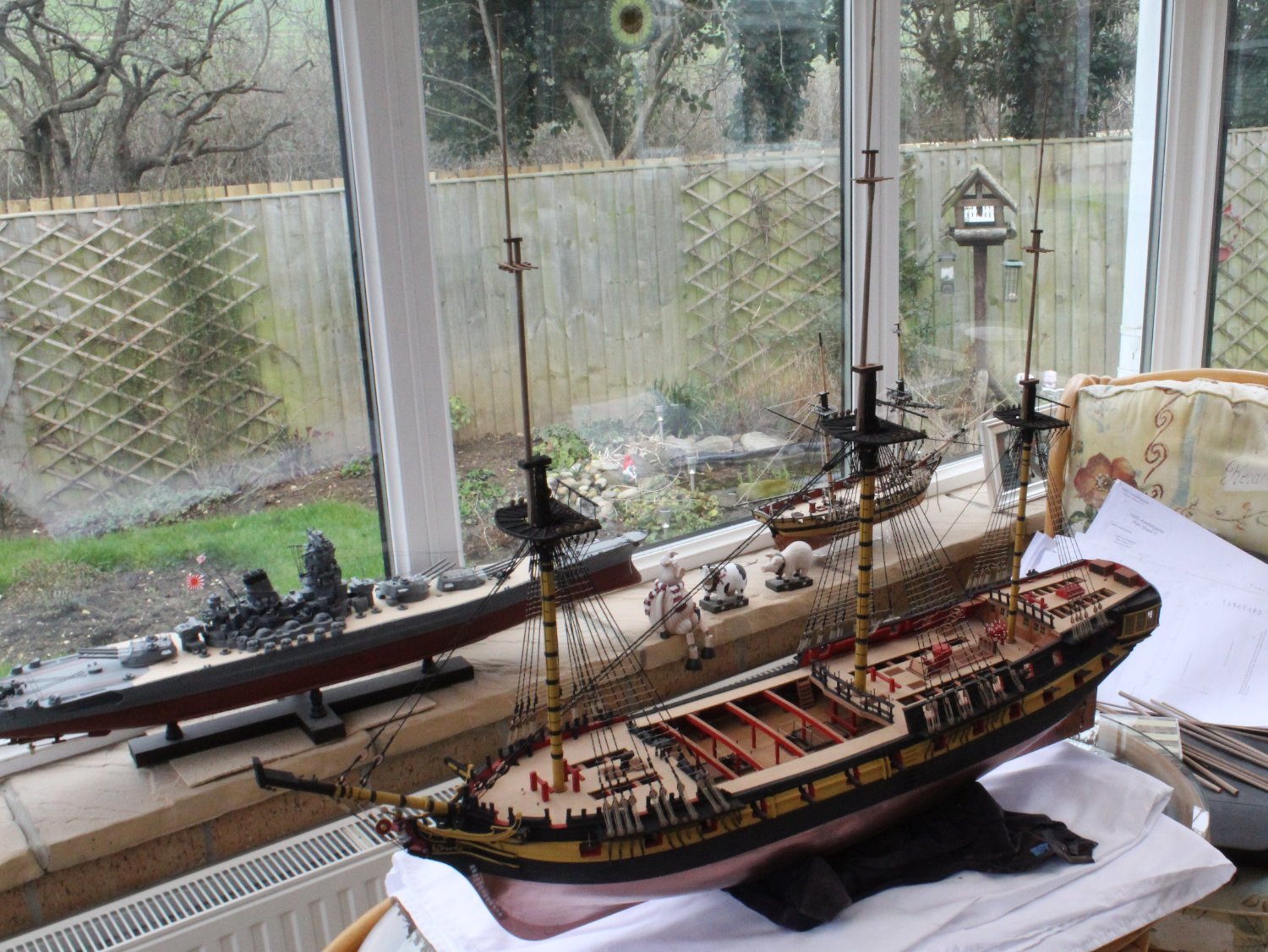
Here are a few pictures of the Indy with all the masts in place, noting the topsail and topgallant masts are only dry fitted. The other models in the background are Speedy (incomplete), IJN Yamato, Alert and the Duchess of Kingston


HMS Indefatigable 1794 by Glenn-UK - Vanguard Models - 1:64
in - Kit build logs for subjects built from 1751 - 1800
Posted
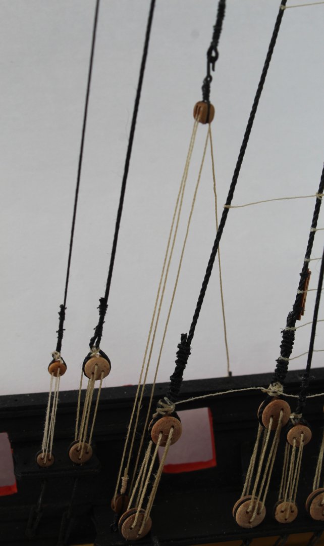
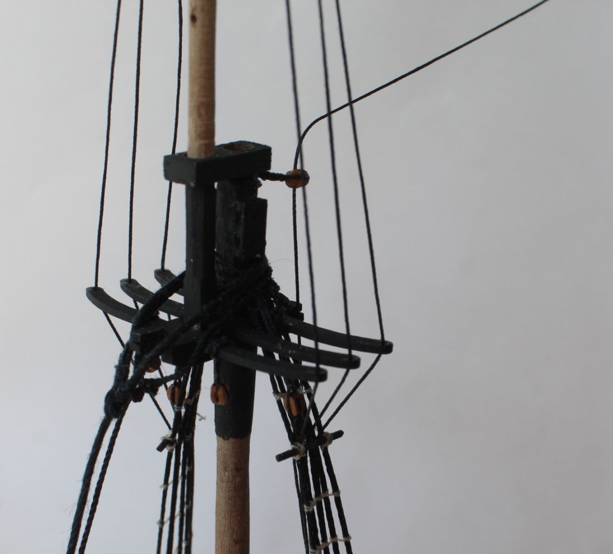
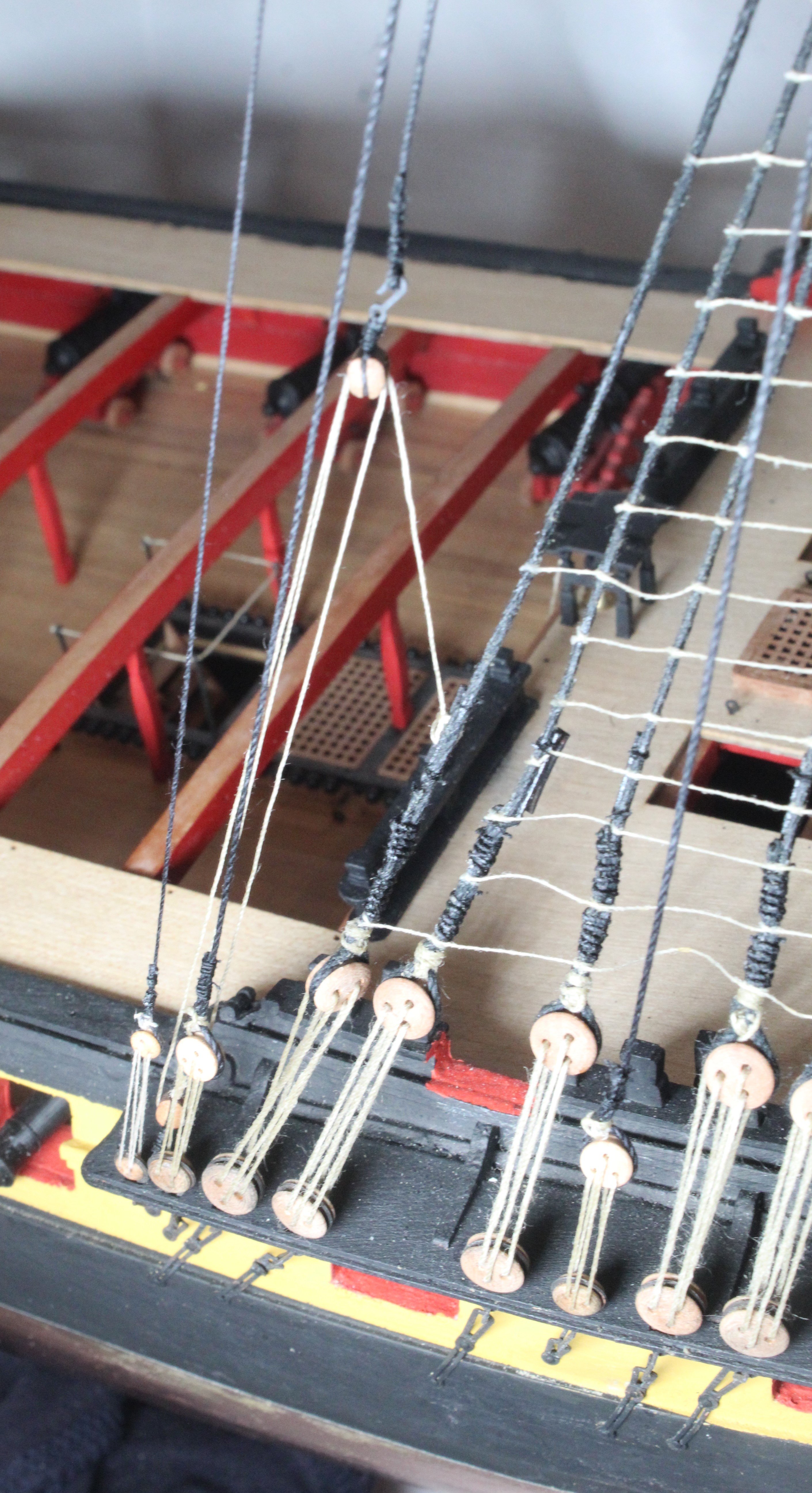
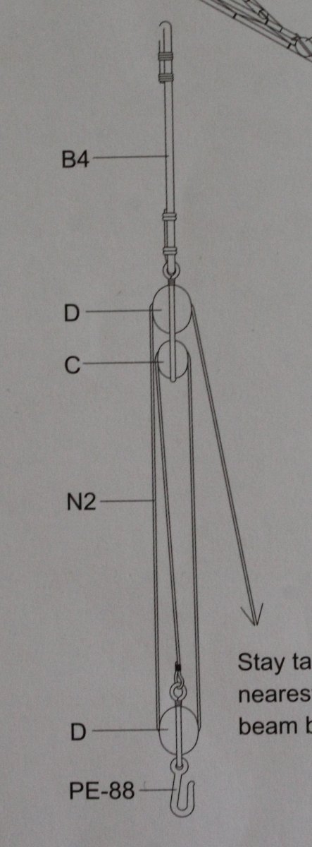
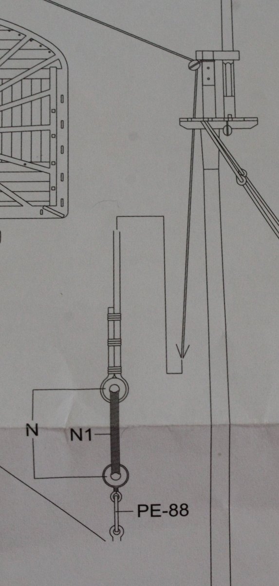
Main Stay Tackles
Todays task was to add the two main stay tackles. There are a number of belaying pins that need to be added to the beams, as a couple of these are required for belaying the stay tackle rigging. It would have better if I had fitted these belaying pins before the beams were installed as the locating holes needed to be opened up a tad. For the most part this was easily achieved.
One hole was a bit more difficult to open up but thankfully I was able to do it
The belaying pins needed to be trimmed so they would fit flush as are fitted to either side of the beam. Once I was happy with the test fit they were glued in place.
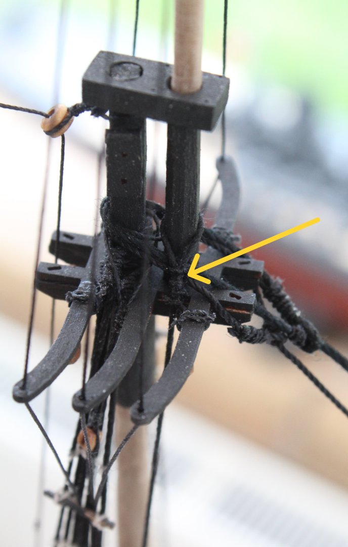
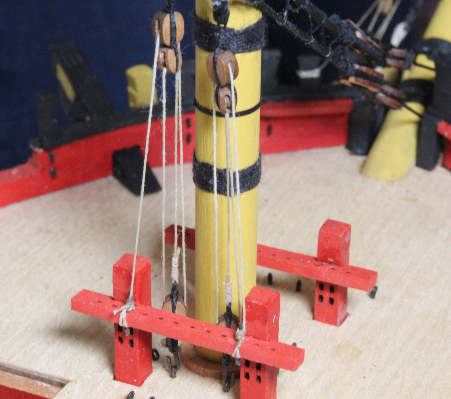
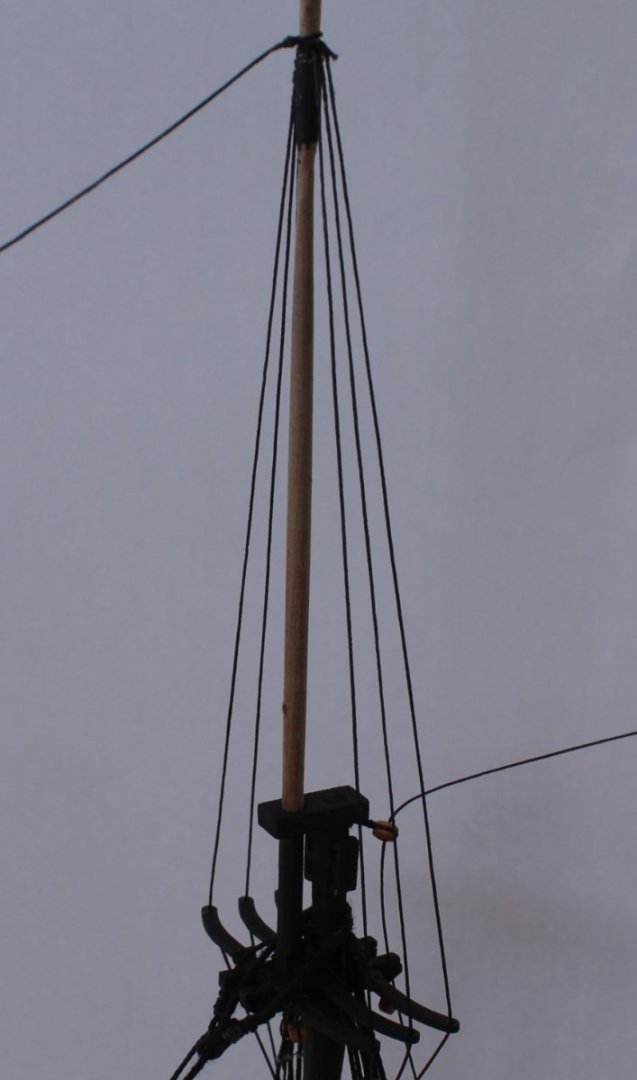
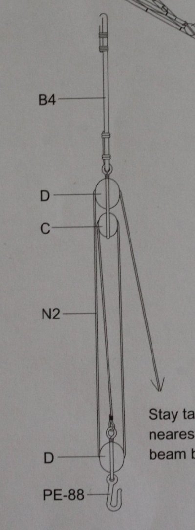
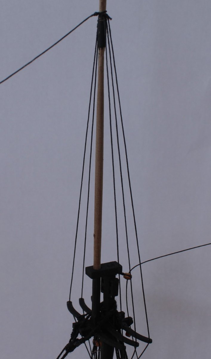
With the belaying pins in place I was then able to fit the two stay tackles. These tackles are indicated by the yellow arrow on the photo below. On reflection I should have positioned the lower stay tackle slightly higher up the stay as it is at a bit of an angle.
The first double block assembly was secured to the main stay.
The bottom block was secured to the beam with a hook and eyelet and once rigged the free end was tied to a belaying pin.
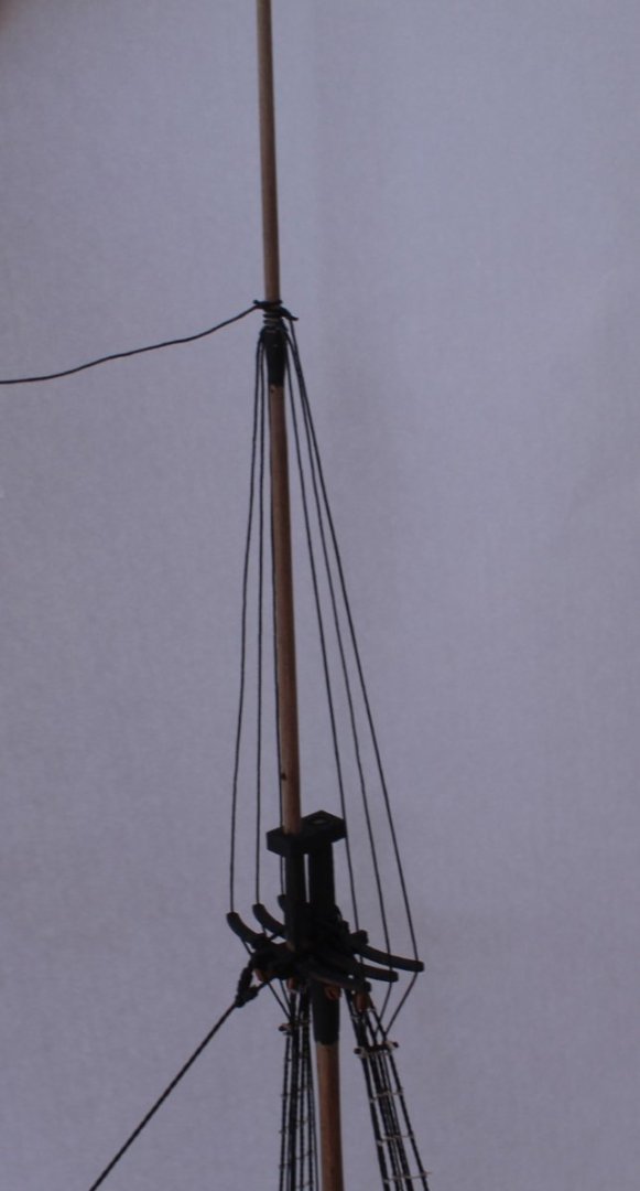
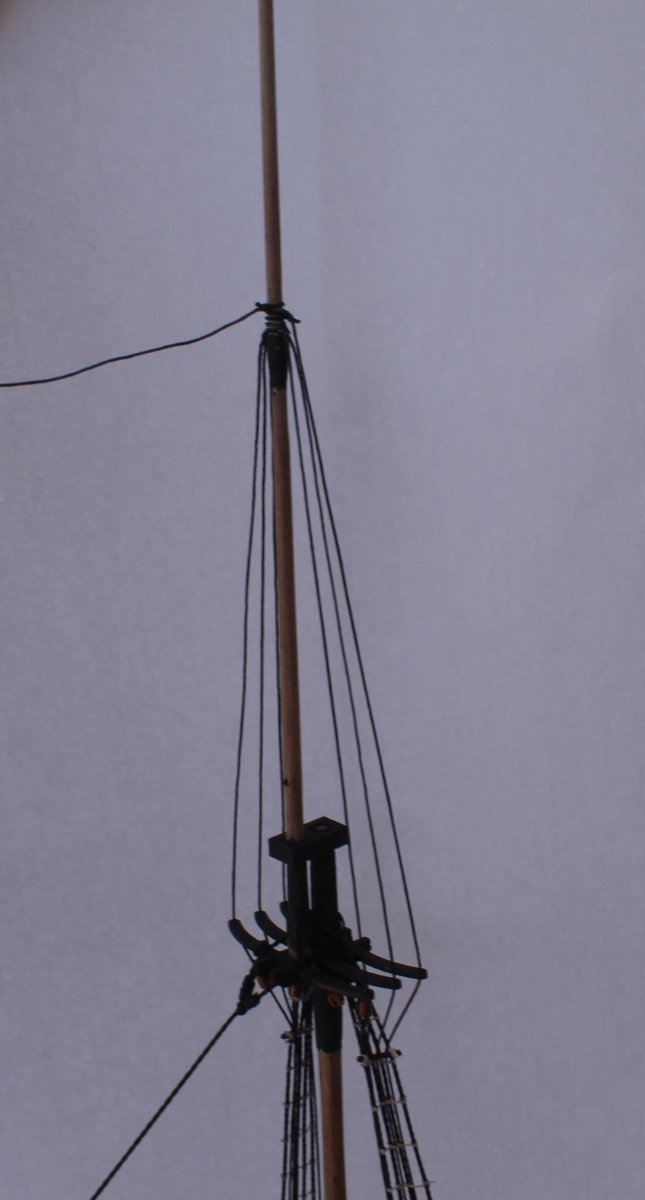
The completed first stay tackle.
The process was repeated for the second stay tackle.