ianmajor
-
Posts
784 -
Joined
-
Last visited
Content Type
Profiles
Forums
Gallery
Events
Everything posted by ianmajor
-
 Don't worry about that. Your meaning is getting through OK. Your diagrams and photos are worth a 1000 words in any language. Thanks for posting them. I am hungry for more! My wife is very interested in your posting to help her with making furniture for dolls houses (her retirement hobby). Ian M.
 -
Druxey, Thanks for that info. I had heard that the ship's boats were all towed during battle engagements, I guess to keep them out of harm's way and also to reduce deck clutter. From a modeling point of view I suppose towed boats would only appear on a diorama. I could leave a couple of boats off the model on the basis that they are "off scene"! Ian M.
-
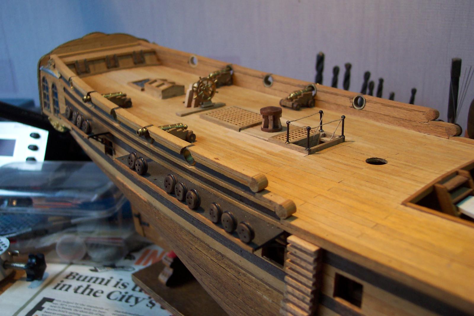
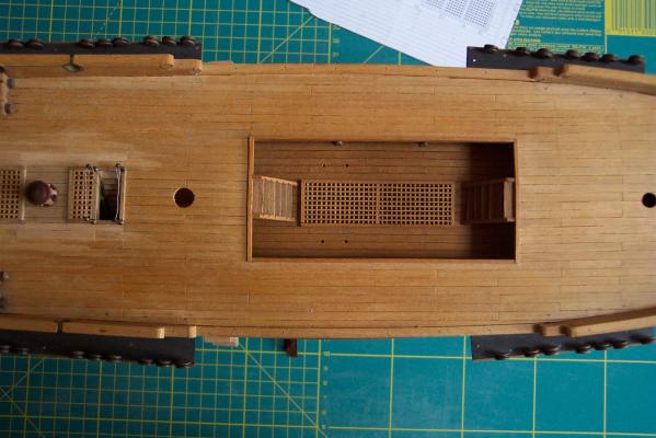
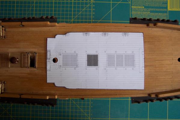
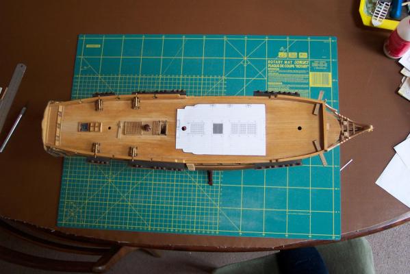
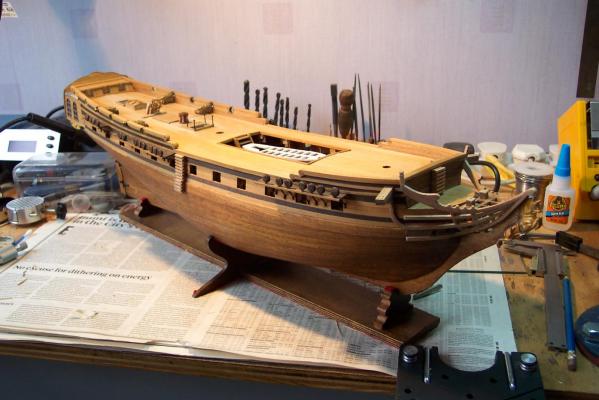
I have been preparing plans for the major surgery. Attached are some photographs with paper cut outs from the plans placed on the model to indicate the proposed new waist shape. I took the detail from Chuck's Winchelsea plans scaled down to 1:75 then slightly foreshortened (Unicorn was a smaller ship). These were altered with real cut and paste involving paper, scissors and glue. Hope Chuck doesn't mind my doing this - don't want to get into his bad books! I post these now to invite any comment or views you may have - other than my insanity which is a given. The cut lines will follow existing planking edges. Two areas of concern. 1) From the second photo you will note the main mast will be moved forward by about half its diameter. In its original position and with chain pumps added it would crowd into the new companion way. Currently the leading shrouds would line up with the vertical centre of the mast. The new position would line them up with a tangent across the rear of the mast. I have seen plans with both of these alignments. This would be offset somewhat by a backwards rake of the mast by a few degrees as per the prototype. 2) The wider waist could put the plywood deck supports on view. They will need some work. Photo 1 the current waist area. Photo 2 shows a cut out from the plan showing the proposed new waist. Photo 3 shows how the whole deck area would look with new shape waist. (This photo features my right foot since I stood on one of our chairs to take it. ) Any comment or suggestions would be appreciated. In the meantime I need to make some more deck fittings. Ian M.
-
decals question
ianmajor replied to PopJack's topic in Painting, finishing and weathering products and techniques
Our friends in aircraft and railway modeling use Micro Sol decal solvent (or transfers as we call them in UK) to soften up the decals to get them to lie better, particularly on irregular surfaces. ( see http://www.microscale.com/Merchant2/merchant.mvc?Screen=PROD&Product_Code=MI-2 as an example source ). But please note it is a solvent so it is best to hone your skills with it on test decals before you let rip on your best ones. Ian M. -
Dave, That is very helpful. Thanks. I was debating between using a pair of spare topmasts or skid beams. My ship was built 1748 so from your response the spare topmasts is the way forward. It does make for an interesting thought. I can spend many happy hours making the detail inside each of the boats then hide that detail by stacking boats with the top one upside down. I suppose it is as per the old adage "at least I know the detail is there". Ian M.
-
Dave, Thanks for that. That is very useful. Sounds like I have quite a bit of small boat making to do! Is there any indication how they would be mounted on the ship? I have seen boats stacked 2 high in the waist area but not sure where the third would go. The ship I am modeling did not have any way of mounting it at the stern. Ian M.
-
I am building a mid 18th century 28 gun British frigate and am making preparations to construct a boat (or boats) for it. Some questions. How many boats would this ship have had and what size/types? Was there any standard that dictated the number/types of boats used? I have looked in Steele ( http://hnsa.org/doc/steel/index.htm ) but could not find the answer (might not have looked in the right place). The NMM's model of Lowestoft (http://collections.rmg.co.uk/collections/objects/66300.html ) appears to only have (what to my eyes is) a 28ft pinnace. Any thoughts? ( I am probably angling for BE to come to my aid again! ) Ian M.
-
Toly, Beautiful work. I would be interested in any extra information you could give about how you made this furniture. In particular the top of the table looks difficult. I would love to see how you did this. By the way - I don't remember seeing such fabulous models when I lived in Moscow 40 years ago! Ian M.
-
ROYAL CAROLINE 1749 by Doris - 1:40 - CARD
ianmajor replied to DORIS's topic in - Build logs for subjects built 1501 - 1750
Doris, I am at one with BE. The small number of tools you use compared to mine put me to shame. I think you demonstrate the importance of a good imagination when determining how to tackle a task. You remind me of an artist teacher friend of mine. His artistic flair means he, like you, can produce masterful work with very basic materials, particularly when handling different paint pigments to get the right colours. I fear this is an ability that is inherited rather than learnt so I will have to continue with my trunk full of tools! Ian M.- 881 replies
-
- 1
-

-
- royal caroline
- ship of the line
- (and 1 more)
-
Peter, Thank you for your encouragement. Indeed your build log in MSW 1.0 was the very thing that caused me to look at how I could improve my work and model (I started by buying Petersson's book). If I may be cheeky I will probably send the odd PM to you to seek advice. A thing about spending as long as I have on a model is that one's skills change greatly over that period of time, either for better or worse. The appearance of variation in quality between the older and newer parts is inevitable. However, after the next phase where I am going to open up the waist area, I may have to rename it "The Wreck of the Hesperus" if it goes horribly wrong! Ian M.
-
Question on old kits - Moved by Moderator
ianmajor replied to PopJack's topic in Wood ship model kits
Brian, I am making a Coral kit that has plans dated 1974 and I bought it in 1975. It is not accurate but makes up in to a nice model and is not that hard to make. This kit is still produced and available. What is apparent from build logs where similar models have been made from later production kits is that some of the problems with my kit have been corrected in later years. My view is that if you do an "old" design kit it will probably not be as accurate or as easy to make as modern kits. This is due to a variety of things. New kits are laser cut using CAD, so the parts should fit together well (if they don't it is unforgivable) and finer detail can be produced. The old pencil and paper designs and saw cut parts can be more variable. When pre '90s kits were designed there was no Web so researching was more difficult - it was possible to do the full research then but would have increased the cost due it being labour intensive. Materials available to modelers has improved and new techniques developed which all impact on the quality of a kit. I guess it is like riding a bike, get an old one whilst learning, then get a new one! Ian M. -
Nico, This is a fabulous build. I had a wonderful holiday with my wife in Venice last year and this takes me right back there. From your photos I feel I can almost climb on board and be back on the Grand Canal. Ian M.
-
I am now looking at the waist area of the ship. The Lymm class frigates were far more open in this area than the kit represents. So I feel some major surgery coming on. The advantage will be that it will be nearer to the original, plus I will be in a position to model some chain pumps and oven. Looking forward to that. If it goes wrong I may be producing a lot of firewood!
-
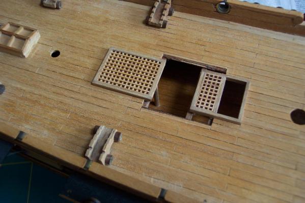
And now for my Homer Simpson moment. I was inspired to build this deck cluster after seeing BE's Pegasus (http://modelshipworld.com/index.php?/topic/332-hms-pegasus-by-blue-ensign-victory-models-enhancing-the-kit-a-build-log-of-sorts/ ) and Chuck's Winchelsea (http://modelshipworld.com/index.php?/topic/99-hms-winchelsea-by-chuck-1764-english-32-gun-frigate-pob-164/) where you will see similar deck grouping. It was after I completed the work that I had a closer look at the Lymm plans at NMM. The two Lymm class frigates had this cluster the other way around ie the companion way was next to the wheel. As that great yellow man would say - Doh! Ian M.
-
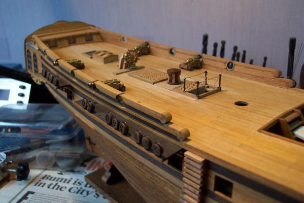
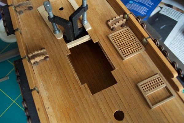
The companion way was then fitted permanently in the hole in the deck. I cut some 1.5mm walnut sheets in to planks to make partners for the drum head. These were fitted between the new gratings covering the rest of the base wood. I used one piece of deck planking under the front of these as packing so that they sat horizontally (the deck slops down at this point). Then I put replacement deck planking around these too complete the repair. The next photo shows this work completed with the drum head in its new position. Behind the wheel is standing temporarily in place. The next view is the whole ship in its current state. I have done some work around the heads area including adding seats of leisure - the dock yard workers now have somewhere to sit whilst they read their daily papers.
-
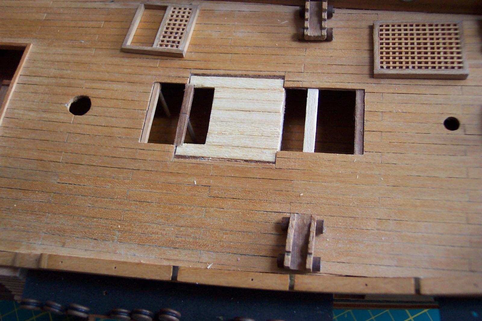
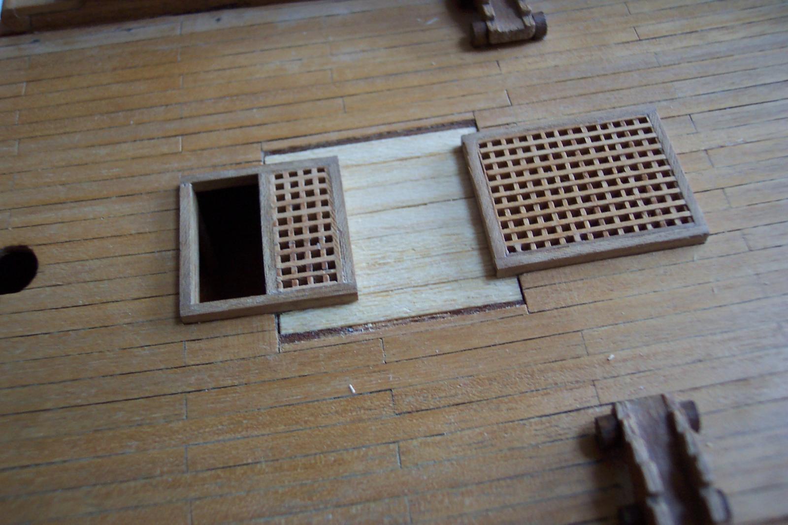
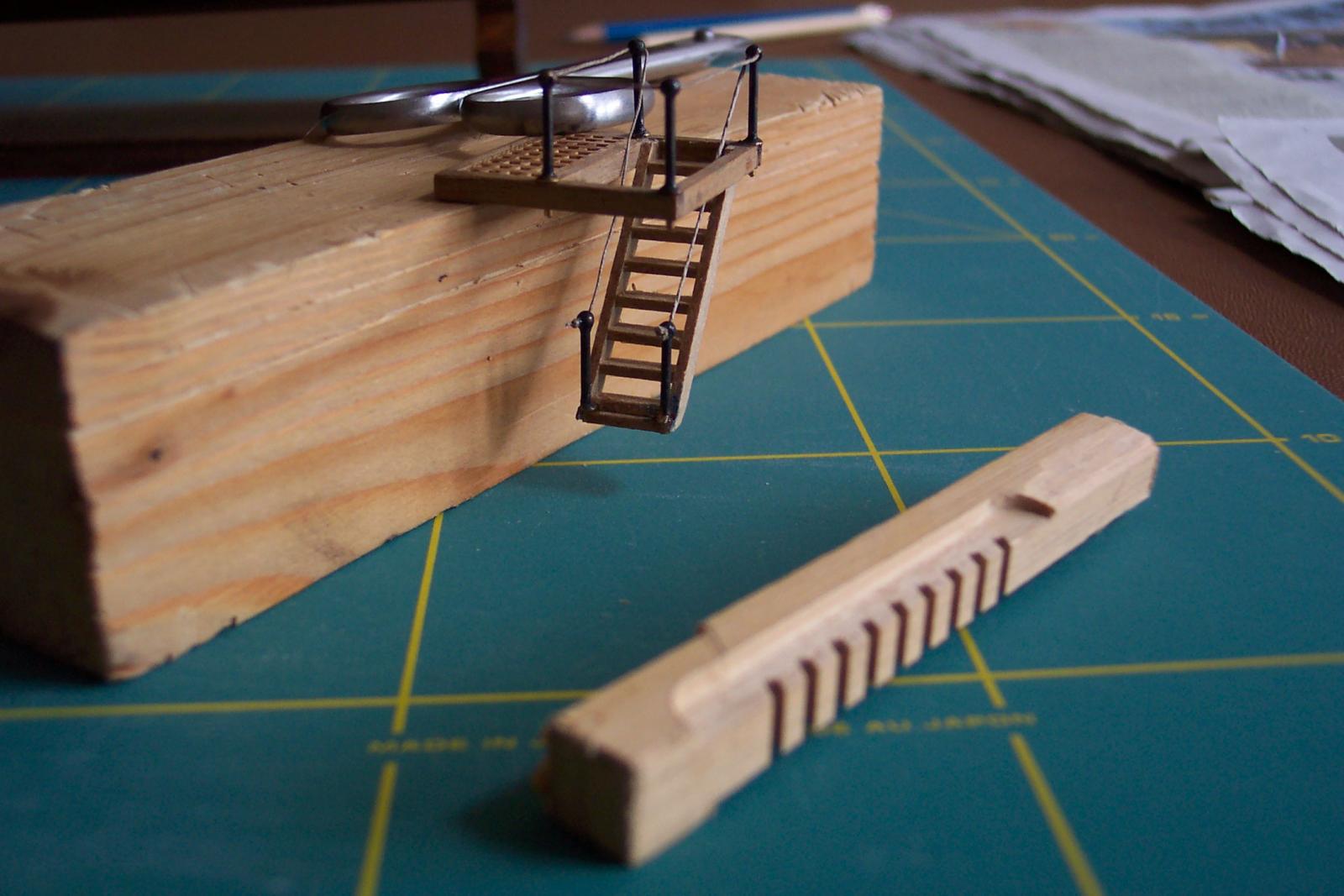
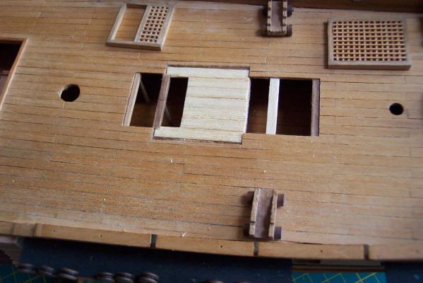
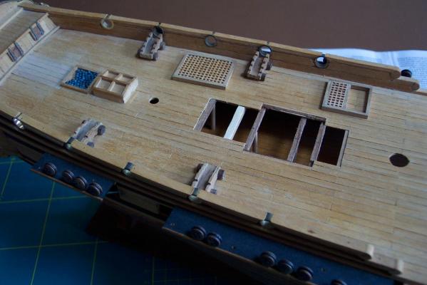
The next stage was to fill in that part of the hole not covered by the new gratings. A layer of basewood planks 1.5mm thick were used. Again I made sure the new gratings would still sit properly. Then came construction of the companion way ladder. The photo show the completed companion way waiting to be fitted in to the hole in the deck. The stantions were meant to go along the waist of the ship but I am replacing them with hammock cranes. At the front of the picture is the jig I made to assemble the ladder. Dafi gives some good words and photos on this subject at http://modelshipworld.com/index.php?/topic/445-companion-ladders-advise-needed-please/


-
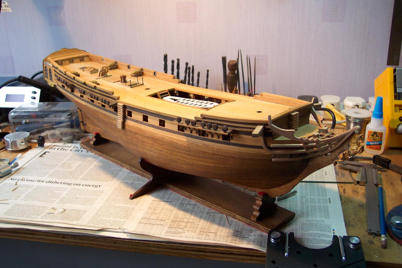
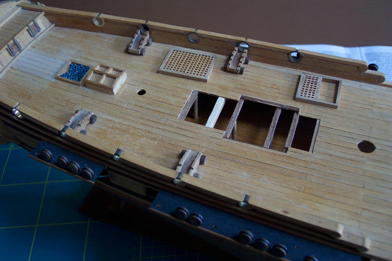
"Oh no he is at again" said my wife when she saw the look on my face as I stared at the Unicorn quarter deck. She recognized my expression as one that indicated that I was not happy about something. In this case it was the large square grating fitted as per the instructions. I decided it had to go and be replaced by two smaller gratings and a companion way. This would be closer to the original ship layout. So off came the grating and the hole in the deck was altered to take the new fittings. This was going to involve some filling in the deck necessitating some additional beams for support. The new beams would have to be propped near the centre line. The first photo shows the exposed hole in the deck extended fore and aft. It also shows the first new beam being fitted. The light coloured beam was an original exposed in the process. The next photo shows all the new beams in place. The left three support a new grating, the right three the companion way and its associated grating. The props for the beams can just be made out. The beams either side of the companion way have props positioned to match the real ship. Also on view are the new gratings sat on the deck. These were carved out of the removed grating. Photo three shows the gratings temporarily placed in their final position to check their fit and to make sure that the sat down neatly on the beams leaving no gaps.
-
Wasa by Lin Feng - Sergal - 1:60
ianmajor replied to Lin Feng's topic in - Kit build logs for subjects built from 1501 - 1750
Beautiful work. I will watch this with interest. Ian M. -
Cool tool lathe Unimat (moved by admin)
ianmajor replied to Sjors's topic in Modeling tools and Workshop Equipment
Oh dear...... When I was supporting large mainframe computers I found out some of my customers' senior management gave me the nickname of "The Angel of Death" because when ever I arrived in their car parks they knew they had a nasty problem which I was there to tackle. Don't want to get the same handle here! Perhaps I should create a tools log on how I improve my small lathe. Ian M. -
Cool tool lathe Unimat (moved by admin)
ianmajor replied to Sjors's topic in Modeling tools and Workshop Equipment
BTW there is a good article by Eric Tilley in Articles/Downloads in the Ship Model Materials and Tools called Lathe Work 1. http://modelshipworldforum.com/resources/materials_and_tools/LatheWork1.pdf The first part is a does and don'ts advice. The second part is good summary of various lathes. Well worth a view if anyone is thinking of buying. Ian M. -
ROYAL CAROLINE 1749 by Doris - 1:40 - CARD
ianmajor replied to DORIS's topic in - Build logs for subjects built 1501 - 1750
The children are fortunate to have such a good teacher. Ian M.- 881 replies
-
- 1
-
-
- royal caroline
- ship of the line
- (and 1 more)
-
Cool tool lathe Unimat (moved by admin)
ianmajor replied to Sjors's topic in Modeling tools and Workshop Equipment
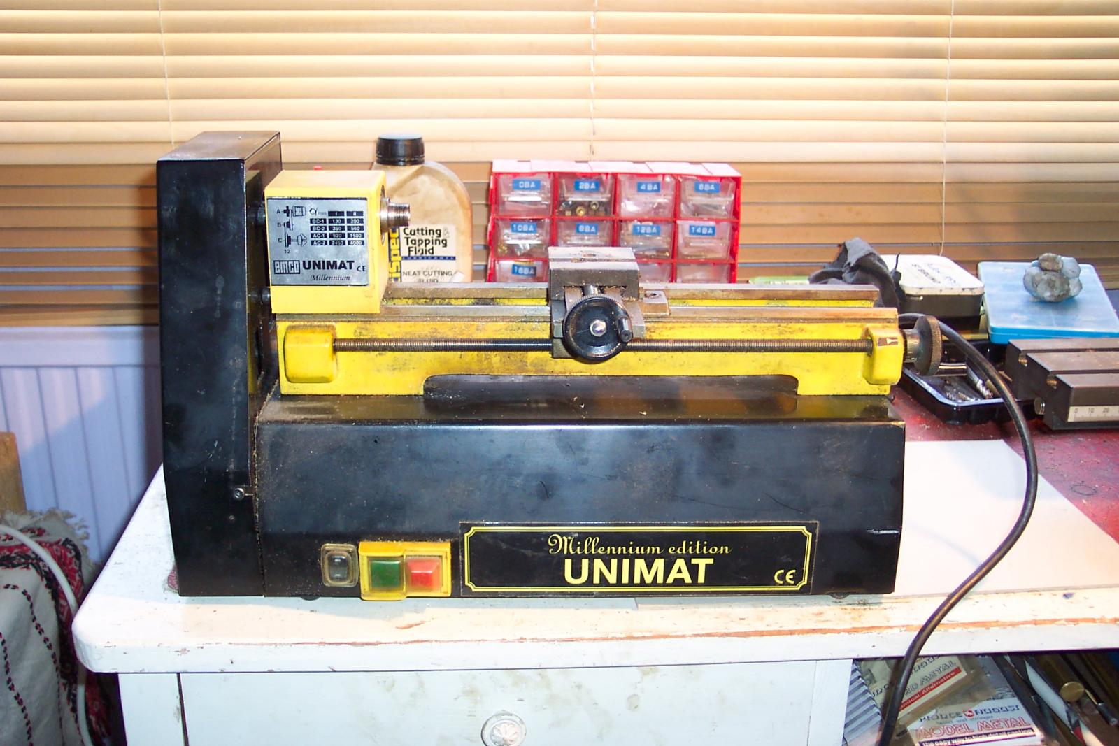
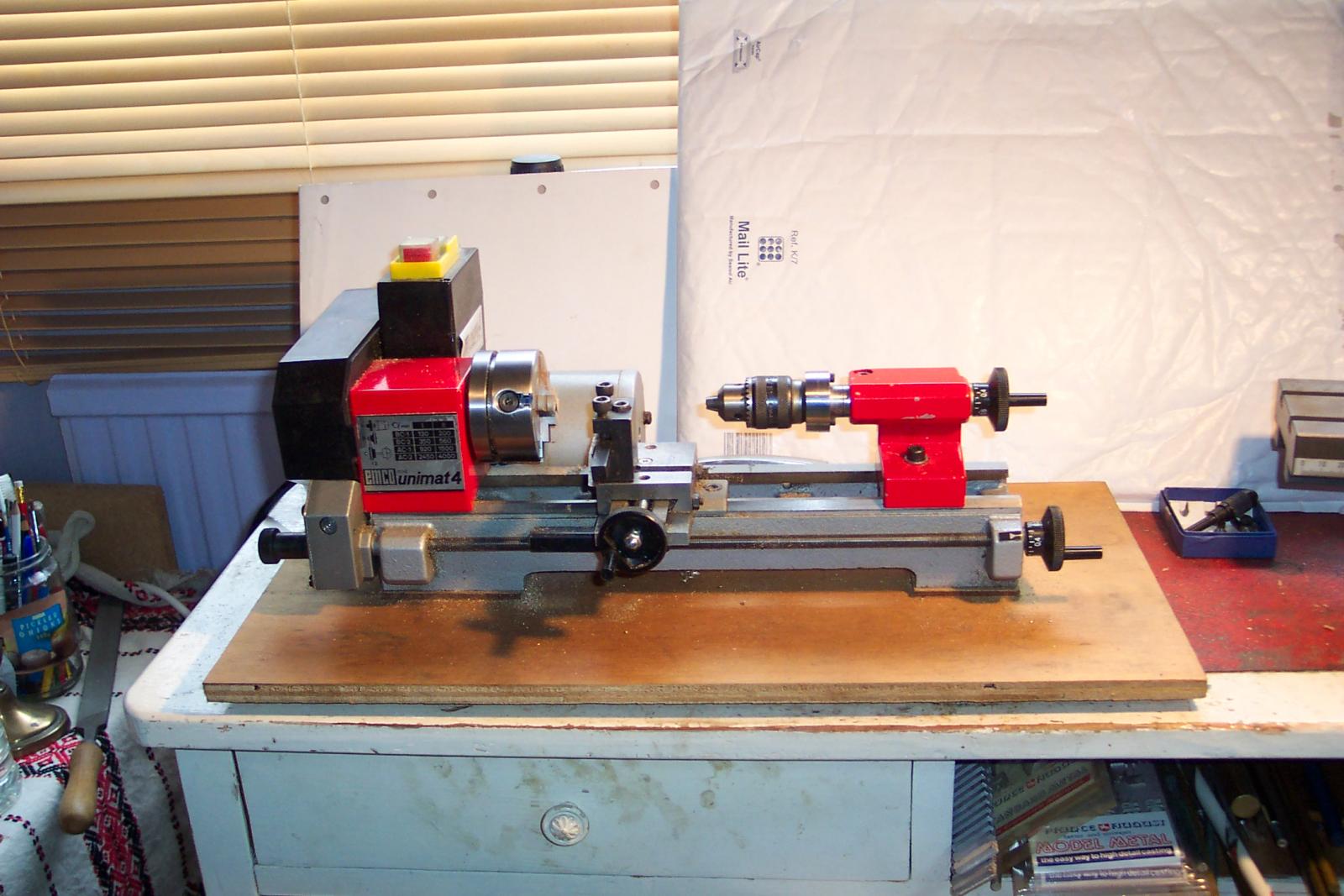
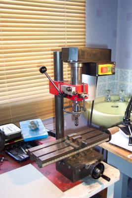
Dave, Re the belt sizes, the Standard Unimat3/4 belts come in three sizes, 1 for motor to idler, one for idler to headstock pully and a small one for the auto feed mechanism. The non standard belts I was referring to were for the Unimat Millenium issue. This was a nice little lathe (which as its name suggests was produced around the year 2000) which had the standard U3 bed mounted on a metal box. The motor was contained inside the box below the bed. This required a fourth belt size which was much larger than any in the standard set. It was this belt that I had difficulty sourcing and of course would always be the one that broke! My Millenium U3 had no facility for mounting a milling attachment as shewn in Harvey's photos, the cast plate on the rear of the bed was too small and was not drilled and tapped to take the fitting. The Millenium U3s are metal painted yellow. The U4 that I have had issues with was obtained new about 2 years ago. It too is metal and is painted red. I think the message I am taking from this thread is that the EMCO U3/U4s that are greater than 10 years old are better than the current batch of metal ones. Having had initial problems with my new U4, by carefully shiming the headstock and making one or two other adjustments and correcting machining errors I now have a nice little lathe. I like the look of Harvey's lathe. The motor looks more substantial that the one supplied with mine. I too have a milling attachment but have it mounted on an indexing table - I need this when I am milling locomotive frames so not as applicable to ships. The interesting comparison is that Harvey's motor mounts on the left of the quill whereas mine mounts on the right - on mine the operating lever has to be on the left which suits me 'cos I am left handed! Thought some photos might be of interest. The first is the EMCO miller which is similar to Harvey's but note the motor is on the right. The small aluminium block on the left of the quill is an optional extra to give measured vertical movement. The index table is from EMCO and is very nice. The second picture is my Millenium U3, out of action needing a long belt plus a replacement motor. My intention is to renovate this for one of the grandchildren to use. Notice the large metal base that contains the motor. Apart from the non standard belt this was a very good arrangement with the motor out of the way of the work area. It looks rusty in the picture - it isn't, simply an effect of the lighting. The third is my 2 year old U4. To tackle the badly alligned centres I shimed the headstock and also added an adaptor on the tail stock to allow some horizontal and vertical adjustment. The latter is the cylinder between the tail stock and the chuck. This adaptor also allows a small ammount of deliberate offsetting of the tail stock centre to do taper turning. Ian M.

-
Floyd, Hubert's "Wooden Ship Modeling for Dummies" web site is still at http://www.shipmodeling.ca/aaplandusite.html#p. As you say his guides are very useful - there is all sorts on there - including coilling ropes ( to avoid my going off subject ). Ian M.
-
Jay, Would the fellow you refer to be Hubert Sicard? He produced a nice video demonstrating his rope coiling device made from old CD covers. This can be seen at http://www.shipmodeling.ca/aa000099av.html. Ian M.
-
Cool tool lathe Unimat (moved by admin)
ianmajor replied to Sjors's topic in Modeling tools and Workshop Equipment
EMCO Unimat lathes used to be good when they were manufactured in Austria but manufacture has now, I believe, been moved to Taiwan and the quality/accuracy of the tool appears to have deteriorated. I had a Unimat 3 Millenium which I was happy with. However it required special belts which were hard to come and when the motor failed a couple of years back I decided it would be cheaper to get myself a replacement EMCO Unimat 4. For a variety of reasons (including a spell in hospital) I did not use the new lathe for some time. When I did I had a lot of problems with it - if it hadn't been for this delay it would have gone back. Subsequent to my buying this tool I found a lathe comparison site in the US which showed that others shared my experience. The main problems. 1) The tail stock clamp did not work. Easy to fix - the slot in the side had been cut too short. 2) When I came to do some end drilling I put a slocum (centre) drill in the tail stock but found that instead of drilling in to the work piece it scoured a circle with a 1.5mm diameter on the end. Putting centres in the head and tailstocks and bringing them together revealled the two were seriously out of line. If you turned between centres on this lathe you would get a tapered work piece. There is no adjustment in the lathe as supplied so I got an adaptor to go on the tailstock which allows me to correct this error. 3) I can't work out what thread the leadscrew has. I assumed that it was as per my Unimate 3 ie a 1mm pitch. It isn't. Rotating the leadscrew handle once advances the carriage by about 1.3mm - neither an obvious straightforward metric nor imperial scale. I am going to fit a digital readout to improve this. The quality of these lathes may have improved since I bought my lathe but I would suggest caution.