

Sailor1234567890
-
Posts
970 -
Joined
-
Last visited
Content Type
Profiles
Forums
Gallery
Events
Posts posted by Sailor1234567890
-
-
I find warming it up thins it considerably and allows you to get it to run better. Keep in mind that changes the pot life though. I usually sit my cans of a and b in a pot of boiling water for a few minutes to warm them up. My epoxy work has all been full scale though, not model scale.
-
Sweet find.
-
I don't think many folks still build masts like that anymore. It's material intensive and good spar wood isn't cheap. I helped my brother build spars for his boat and I intend on building them for my boat using what's called a bridsmouth construction. If you google birdsmouth mast building you'll find something about it. Uses much less wood than a solid mast, is equaly strong and significantly lighter. All important things in a sailing vessel no matter her size.
-
Real spars are made much as amateur said. An adz is used to square the tree. Next, the taper is marked on the top face. An adz is again used to taper it. Once the taper is made on both sides, it is rolled onto it's side and the taper once again marked and cut on the other two faces. Now you have a square log with both ends tapered. A special tool called a sparmaker's gauge (highly technical tool here) is used to mark these things evenly the whole length of the yard. (mast, boom, gaff, spinnaker pole etc. Even oars could be made this way, any round pole type object)
http://www.onboardwithmarkcorke.com/.a/6a010536216f64970b016300b8845c970d-popup
The spar is then 8 sided. Another gauge of pretty much the same construction will mark for 16 siding of the spar. Only the biggest of spars need to be 32 sided before being made round with planes by eye. Odd how they first square a log before returning it to it's round shape but that's how it was done.
http://www.onboardwithmarkcorke.com/.a/6a010536216f64970b016761ae4f0c970b-popup
-
Schooners carried a number of different sails in that position, depending on weather, what their course was in relation to the wind and even what kind of schooner they were. Stays'ls, fisherman's stays'l, Gollywobblers..... Some were designed to be lowered then raised on the opposite tack. Others were even more odd in that a man was required aloft in order to pass the tack over the stay in question. It all depends on what kind of sail you're going to portray. This of course changes how the sheets would be rigged. Hope that helps.
-
I don't just look in here, I might be considered to stalk this one.

-
Looking great.
-
Awesome. Looks really good. Can't wait to see her rig. That's going to be one heckuva model.
-
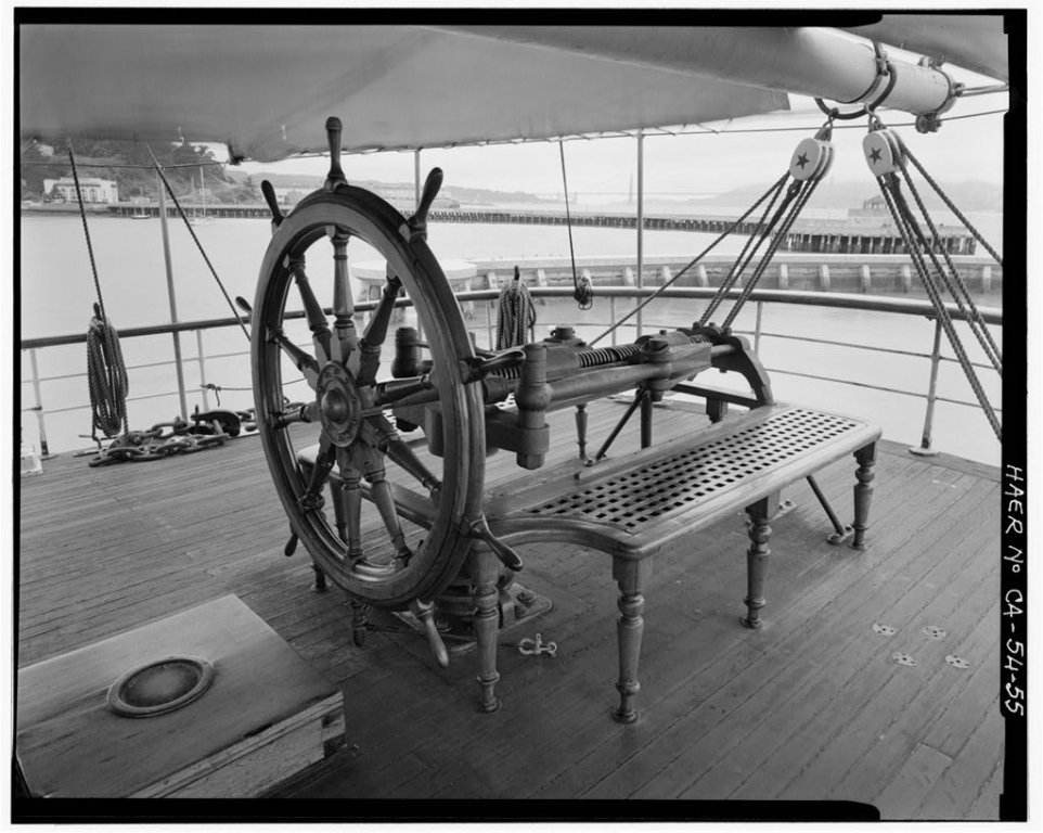
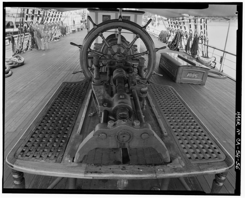
Not really all that complex. The wheel turns the shaft in the middle. The shaft is threaded with a left hand thread on one and and a right hand thread on the other end. The "lugs" are threaded to match, one each. when the wheel is turned in one direction, the lugs move toward each other and in the other direction away from each other. They force those little slide mechanizms to push and pull on the rudder head at the same time thereby turning the rudder. There were variations on this, some used two threaded rods.

-
Trying to add a side view that shows the angle of the wheel and the gear as well as the emergency steering tiller.
I managed to load two pictures but the third one I can't for the life of me figure out what I did.... Oh well,here's a link to the page with those pics on it.
-
I hope this helps you visualize what you're building.
-
That looks great. It's called the steering gear box. It contains the mechanism that converts the rotational force of the helm to the rotational force of the rudder post. The reason it's angled is because it's easiest to make the gearing meet at a 90 degree angle and the rudder post isn't straight up and down. the wheel will act at 90 degrees to the rudder post and therefore the helm isn't straight up and down either.
-
-
-
That is one beautiful build you've got going on there.
-
-
Looking sweet there. Only problem is your last comment. No more posts until the new year.

Have a great Christmas season Ed. Look forward to upcoming posts next year.
-
That's odd. Well good luck with the build. Looking forward to seeing her rigged.
-
-
-
I supose I was a little off in my guess then. A windlass is for the anchor. Winches would be for the cargo. A windlass has an axle that turns on a horizontal axis. A capstan turns on a vertical axis. I have no idea about those other parts either.... There's no description or name for them in the instructions? Maybe a picture of where they go? If you have that I could probably tell you what they are. They are an odd looking part considering the cabin ends with port lights are already installed on the model.
-
-
Those pieces either side of the figurehead are called trailboards.
-
The funny shaped pieces that seem a bit brown look like the ends of either the pumps or winches to me. There should be some sort of piece to connect them. either throws for the pump heads or drums for the cargo winches.

In need of Tips and Techniques for making Eyebolts
in Metal Work, Soldering and Metal Fittings
Posted
That is a small eye right there. WOW. Impressive.