Fam
-
Posts
185 -
Joined
-
Last visited
Recent Profile Visitors
687 profile views


-
 Obormotov reacted to a post in a topic:
HMS Victory by guraus - scale 1:48 plank on frames
Obormotov reacted to a post in a topic:
HMS Victory by guraus - scale 1:48 plank on frames
-
 muratx reacted to a post in a topic:
Le Colibri 1808 by Fam - scale 1:48 - POB French brick de 24
muratx reacted to a post in a topic:
Le Colibri 1808 by Fam - scale 1:48 - POB French brick de 24
-
Archi reacted to a post in a topic:
A question on working mizzen lateen sails
-
KORTES reacted to a post in a topic:
Le Colibri 1808 by Fam - scale 1:48 - POB French brick de 24
-
Siegfried reacted to a post in a topic:
Le Colibri 1808 by Fam - scale 1:48 - POB French brick de 24
-
Siegfried reacted to a post in a topic:
Le Colibri 1808 by Fam - scale 1:48 - POB French brick de 24
-
Siegfried reacted to a post in a topic:
Le Colibri 1808 by Fam - scale 1:48 - POB French brick de 24
-
Siegfried reacted to a post in a topic:
Le Colibri 1808 by Fam - scale 1:48 - POB French brick de 24
-
Siegfried reacted to a post in a topic:
Le Colibri 1808 by Fam - scale 1:48 - POB French brick de 24
-
Siegfried reacted to a post in a topic:
Le Colibri 1808 by Fam - scale 1:48 - POB French brick de 24
-
 Hi all, and ciao Sergio my friend! Yes I'm still alive, but unfortunately I had to stop the works on my Brig being too busy with another family project... I hope I will manage to resume my shipyard in short time, I'm missing it so much... In the meanwhile I send all the members my best wishes for a happy and prosperous New Year Cheers Fam
 -
Fam reacted to a post in a topic:
La Créole 1827 by archjofo - Scale 1/48 - French corvette
-
Fam reacted to a post in a topic:
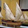
Gokstad Viking Ship by jack.aubrey - FINISHED - Dusek Ship Kits - 1:35 Scale
-
Fam reacted to a post in a topic:
Gokstad Viking Ship by jack.aubrey - FINISHED - Dusek Ship Kits - 1:35 Scale
-
Fam reacted to a post in a topic:
Gokstad Viking Ship by jack.aubrey - FINISHED - Dusek Ship Kits - 1:35 Scale
-
Fam reacted to a post in a topic:
Gokstad Viking Ship by jack.aubrey - FINISHED - Dusek Ship Kits - 1:35 Scale
-
Fam reacted to a post in a topic:
Gokstad Viking Ship by jack.aubrey - FINISHED - Dusek Ship Kits - 1:35 Scale
-
Fam reacted to a post in a topic:
L'Amarante 1749 by giampieroricci - FINISHED - 1:30 - French Corvette
-
Fam reacted to a post in a topic:
L'Amarante 1749 by giampieroricci - FINISHED - 1:30 - French Corvette
-
Fam reacted to a post in a topic:
L'Amarante 1749 by giampieroricci - FINISHED - 1:30 - French Corvette
-
Thank you Dirk! I'm missin but still progressing at a low pace
-
Fam reacted to a post in a topic:
Greenwich Hospital barge of 1832 by druxey - FINISHED - 1:48 scale
-
April 29th, 2016 No words ... just emotions to share Fam
-
Johann you have done this so many times now that it seems a Ford or VW factory, not a modeller workshop! I have three boats for my Colibri Brig, if you volunteer ... Fam
-
Super carving Igor!! I also like very much the weathered effect! Fam
-
Pewter painting
Fam replied to S.Coleman's topic in Painting, finishing and weathering products and techniques
I used Humbrol enamels for my 9pdr guns, then polished with pencil graphite and a rotating brush ... good looking in my opinion, but depends on personal taste Fam -
I think it's correct, RMC: you should start from the bowsprit laying the collar against the stop cleats, then go down and pass the rope through the gammoning hole, keepeng it as much forward as possible. Then up for another loop, with the rope laid forward of the previous loop. Then down through the hole, with the rope laid aft of the previous loop, and so on.... The loops around the bowsprit should be eight to eleven, depending on the period and class of ship. In the end, the rope coming down from the bowsprit is lashed with several loops at the middle of the gammoning, where the ropes cross to each-other, and seized. The loops of lashing should be eight to ten, depending on the period and class of ship. Good job indeed! Fam
-
This is really excellence!! My compliments Fam
-
Thank you all for the kind words and the likes, I appreciate! A
-
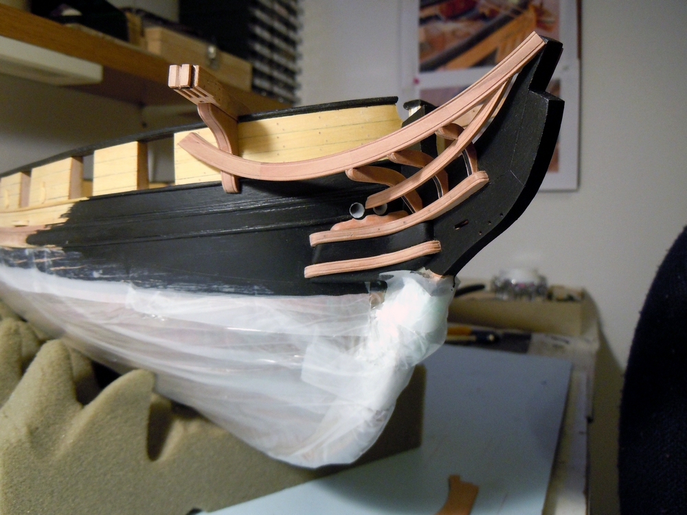
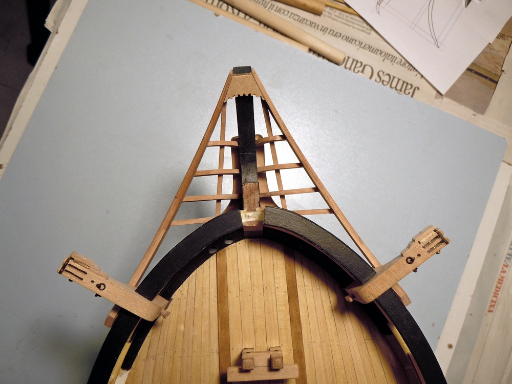
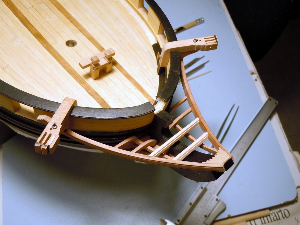
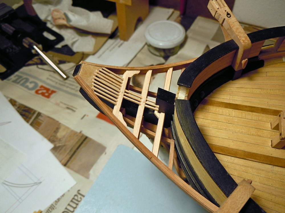
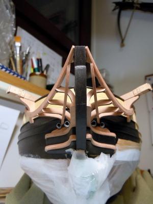
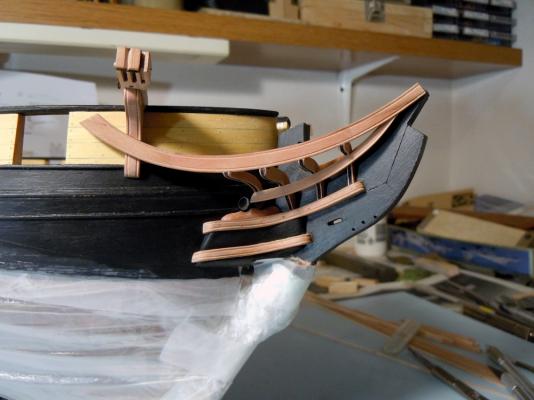
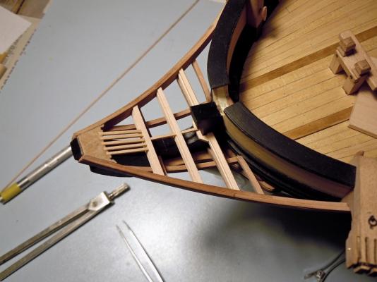
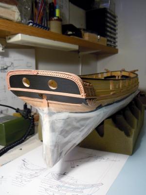
April 8th, 2016 Hi all another quick update about the head-timber works. The third couple of timbers is installed and the lower rail is being test-fitted in the next picture. Note that I had to complete the finish of the three head-timbers in their outer face, for the portion between the upper cheek and the rail, because the latter will obstruct the accessibility to this area for finishing. Therefore I glued a narrow strip of paper, blackened with a felt pen, inside the scraped molding and then re-touched with black acrylic paint to match the bow finish. Here, in the two following shots, the two lower rails are completed and definitely installed. They are monolithic, i.e. built in a single piece, because their size and curvature are smaller and I thought they could be obtained from a single piece of wood. Matching the rail with the three existing head-timbers, with the bow (between the hawse holes) and with the main rail was another “pleasant” task And finally the fourth head-timber is completed and installed: it sits on top of the lower rail (where it touches the bow surface) and is connected to the main rail. All timbers are finished with the black strip on their outer face. Forward platform After completing the lower part of the ship’s head, I have switched to its upper side ... what I call “bowsprit deck” or “forward platform” (pretty sure the name is another, but I don’t know the correct English term). Several cross timbers are laid in athwart direction connecting the two main head-rails. They are longitudinally positioned close to the head-timbers above described, but not precisely overlaid: there is a small shift forward and aft of the two forward-most timbers, to leave space for the bowsprit gammoning. The timbers are intended to support a series of fore-and-aft smaller timbers (or “ledges”?), thus creating a sort of grating, or something that reproduces the carlings-ledges structure of the decks but with the scope of a grating. Connection among the “ledges” parts and the athwart supports should be done with a series of recesses (notches) 1mm wide and 0.9mm spaced apart to each other, like visible on the wedge piece at the head-of-the-knee that I’ve already fixed. The more proper way of doing this job is probably drawing reference longitudinal lines across the athwart beams and then cutting the teeth, with a sharp chisel or cutter, on their fore and aft upper edges. I thought that this method leaves large space for alignment imprecisions, any error in cutting the recesses would reflect in a deviation of the ledges from the F&A direction and from their parallelism. So decided for simulating this method by using instead the method shown here on MSW by Alexandru (Guraus’s buildlog of HMS Victory). I built a step on the fore and aft upper edges of the athwart beams by overlaying two pieces: the lower is 3mm wide by 2mm thick, the upper batten is 2mm wide by 1mm thick: the resulting beam is a 3x3mm timber with two continuous 0.5x1mm steps along the upper edges, which will house the ledges timbers. In this way I will be able to take care of their correct alignment and spacing to each other. The following picture shows the first two cross-beams installed: the steps are visible on the fore edges. Choice of material for the entire forward platform is a lighter shade of Pearwood (Swiss pearwood from CrownTimberyard company, great stuff!!), contrasting with the darker shade of the lower structures. Once again, I couldn’t be happier of my decision to buy a disk sander (Proxxon TSG250/E in my case): once the proper angles needed to match the rails with the beams are found, with some trials, then obtaining the correct fitting for all the cross-beam timbers with the disk-sander is easy and fast, just a matter of few seconds! No need to say I strongly recommend this tool. Here below the third, and last, cross-beam is positioned: it is longitudinally positioned so that it interferes with the stem, that seemed a bit weird to me. But after checking and measuring on the plans and verifying on the model, and then double-checking and measuring again, I got to the conclusion that its position is correct … or better it is compliant with the plans (supposing they are correct). The problem with this position is that the beam, apart from crossing the stem, is not able to support the longitudinal grating. So I added another small piece just forward of the stem and connecting the two parts of the beam: probably not the correct solution, but I could not imagine another way out from this impasse. The building method for this cross-beam was the same, simply divided in two parts. The first 5 longitudinal parts of the gratings (ledges) are also installed, to demonstrate the concept. They seem to be slightly not parallel, but it is just an impression from the picture: I ensure they are parallel! And here again the forward platform at a later stage, with more ledges installed and two of the knees connecting the beams to the rails installed: The knees are notched to match the beam step, then I will cut the recesses for the ledges in the after edge of each knee. Finally a shot from the opposite side of the ship: the stern transom is finished in matt black and the moldings and decorations pop-out much more evident. I like very much the way light reflects on the Pearwood leaf decorations, giving them different shades of color that are only due to different orientation of the leaves. Painting of the counter down to the second molding is not yet complete. That’s all for today. Best regards Fam


-
Cutter Cheerful 1:48 by rafine - Finished
Fam replied to rafine's topic in - Build logs for subjects built 1801 - 1850
Hi Bob I just caught up with your build log, after having read you first posts some time ago I forgot to mark it as 'follow this topic' so missed all your more recent updates. I wasn't aware you have almost completed the beautiful Cheerful, it's really awesome: I like everything of this little boat and the crispy way you have built it! So instead of hitting the 'like' buttons I prefer telling you directly: you did a great job! Thank you for sharing Fam- 525 replies
-
- 3
-
-
- cheerful
- syren ship model
- (and 1 more)
-
Thank you so much Johann, I really appreciate! You already know, you are my reference for learning so many how-to-do items and I consider you my teacher I just watched at your videos on youtube... they are astonishing! A liked a lot the choice for the side music...it is the original from which the violin-cello duet between Jack Aubrey and Stephen Maturin is derived, isn't it? The last shots of 'Master and Commander'..one of my preferred movies Fam
-
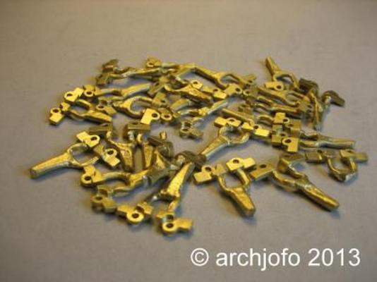
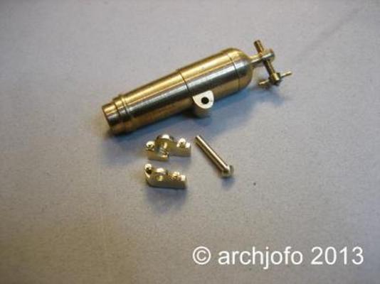
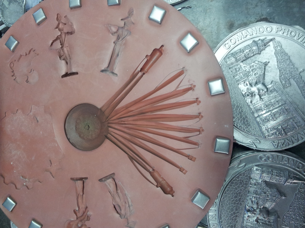
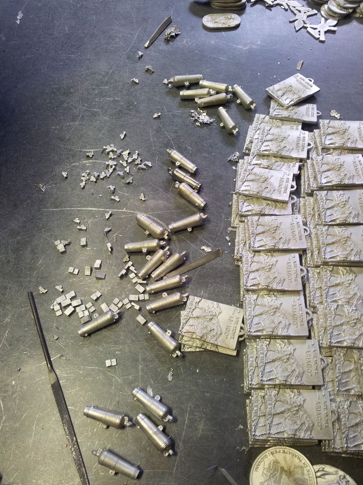
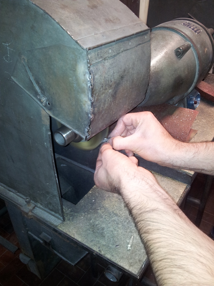
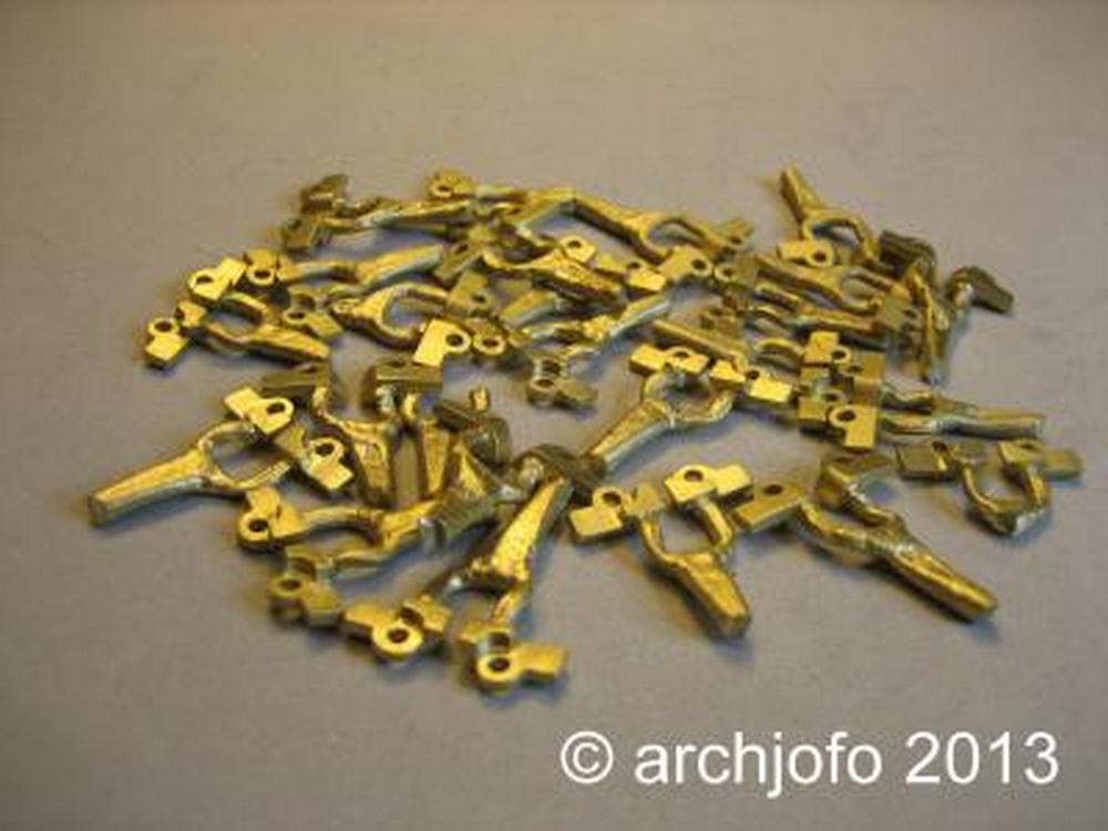
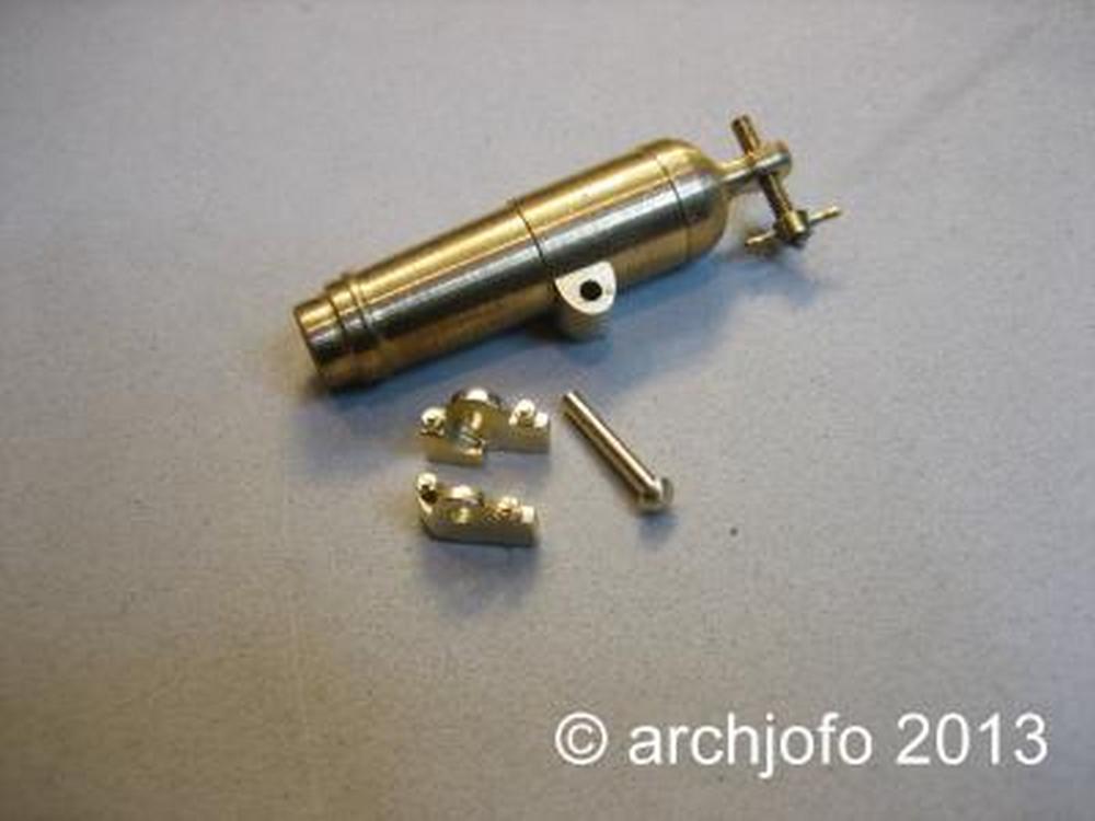
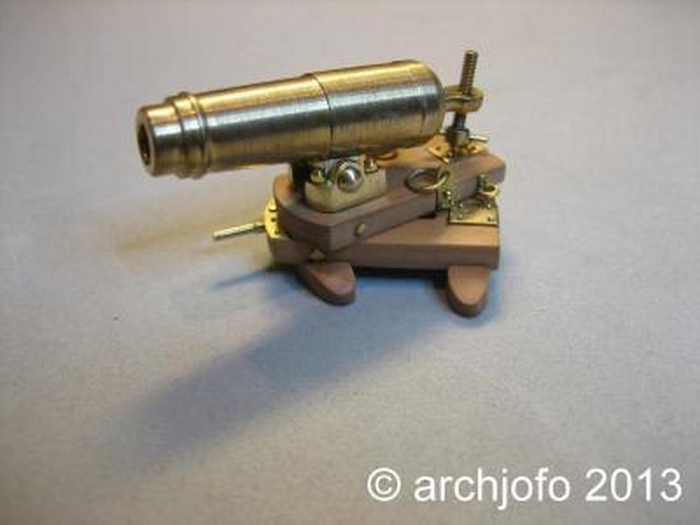
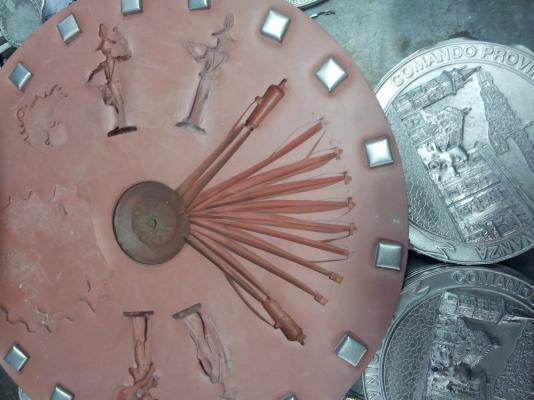
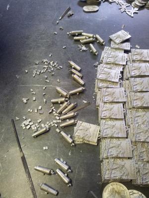
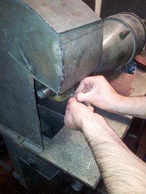
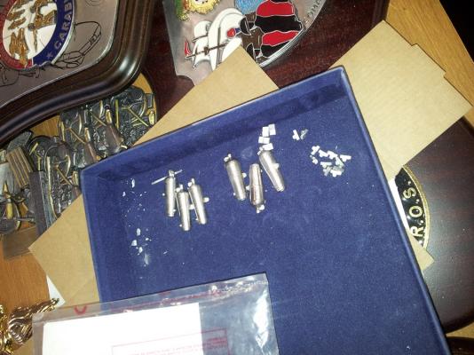
For those who don't have access to the German forum where Johann is posting his work, I show here three steps describing what I'm trying to obtain (Johann if this is disturbing just let me know and I'll remove the images immediately): - cast support parts for carronade barrel - unassembled parts - the completed carronade All his pieces are brass, either lathed or cast. I was not so lucky, so all my parts will be cast in pewter. The final finish will be in gun-metal paint, polished with some lead pencil dust to improve the metallic look. The 9pdr long gun pictures I posted some time ago show what I mean. I'd like to highlight that the design of my barrels seem to be exactly the same of Johann's, but I only referred to Ancre plans: probably the weapon was the same type for both ships, regardless of the different years of building. Also note how the lower part of the carriage has no wheels, and carronade training is done by rotating the upper sledge ... this seems to be a little bit weird, but I don't have the knowledge to contest this layout. Cheers Fam