mar3kl
-
Posts
178 -
Joined
-
Last visited
Content Type
Profiles
Forums
Gallery
Events
Everything posted by mar3kl
-
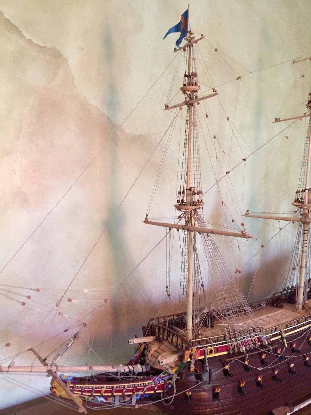
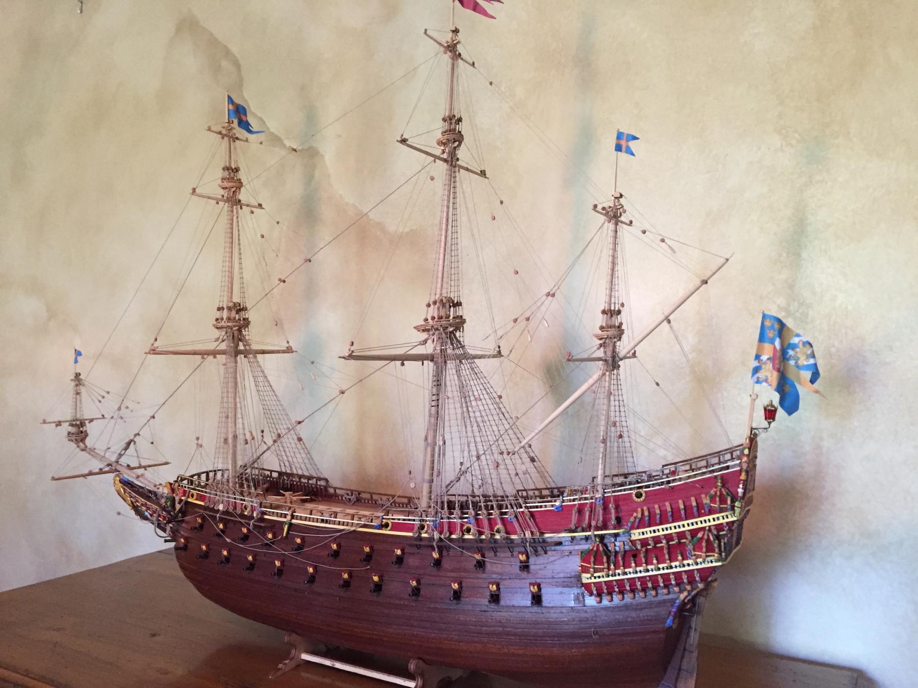
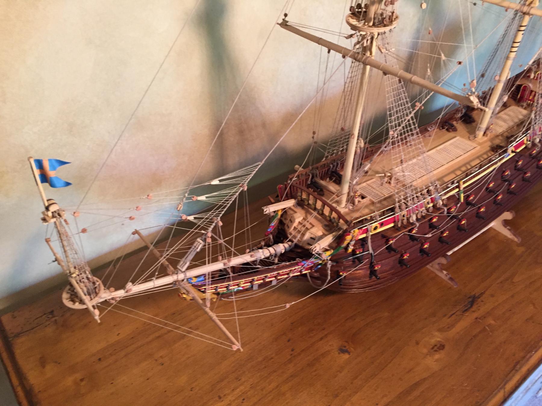
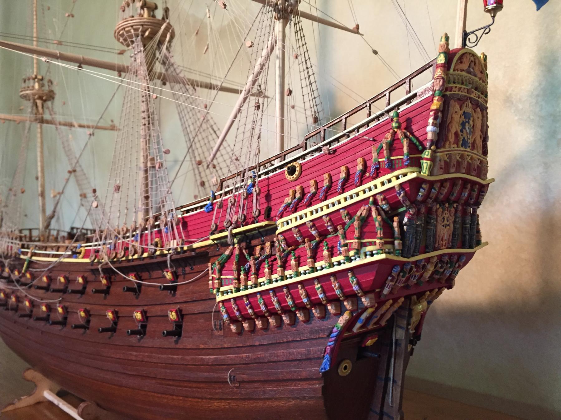
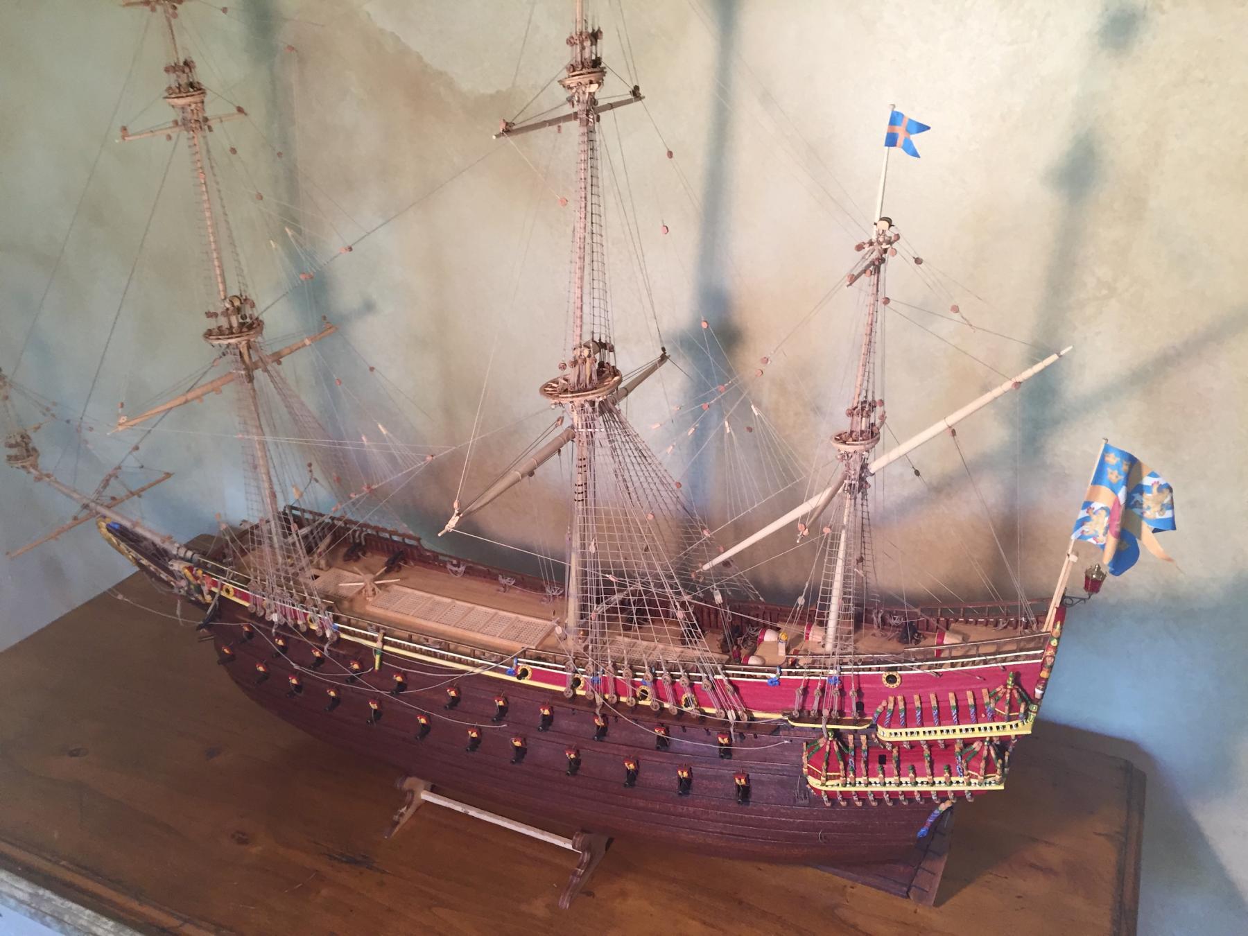
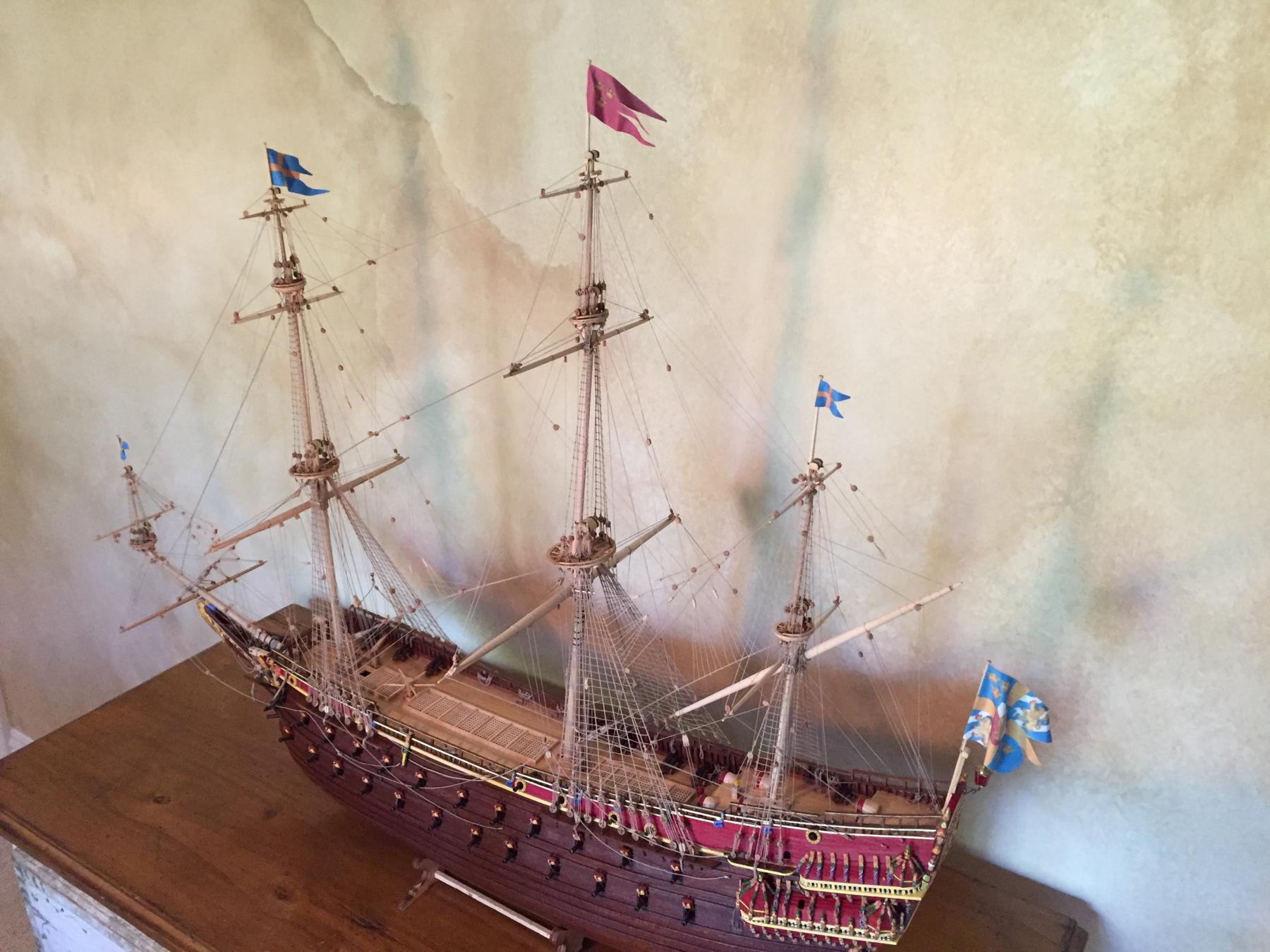
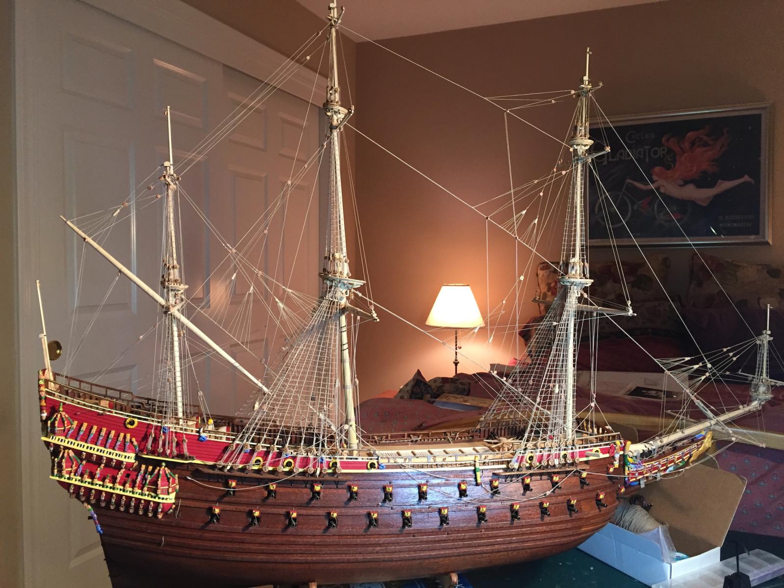
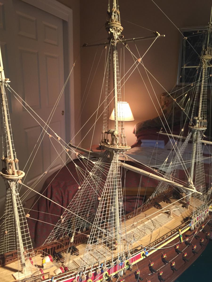
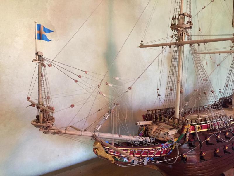
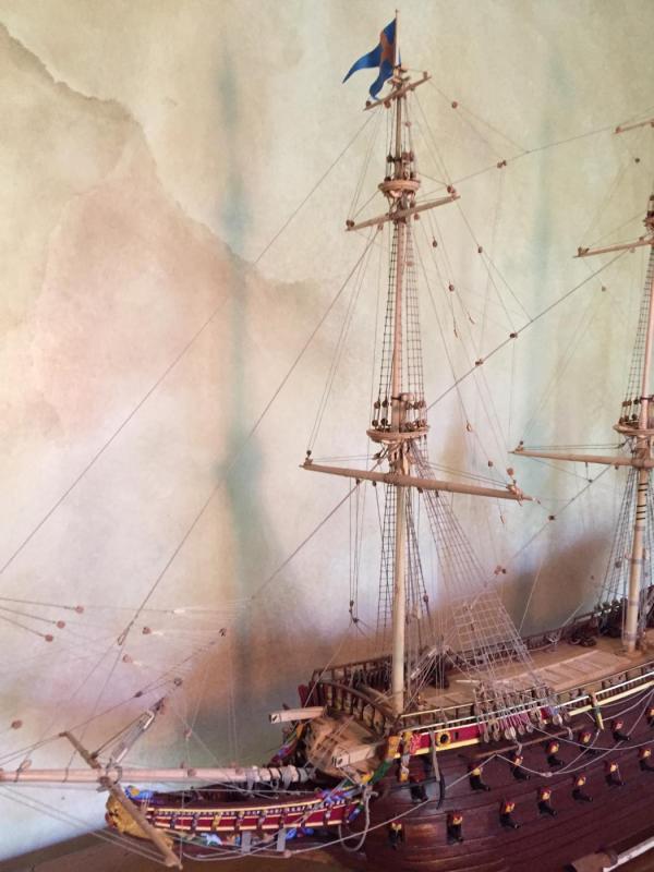
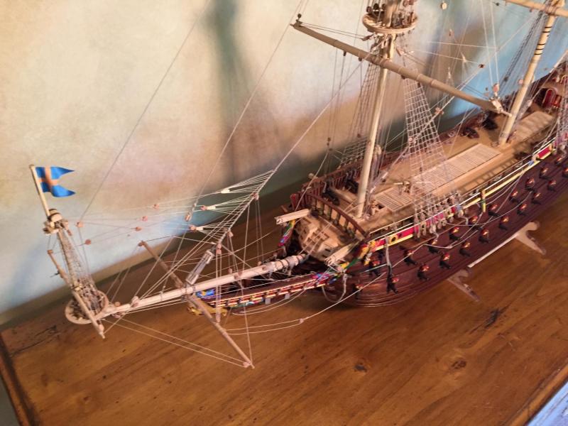
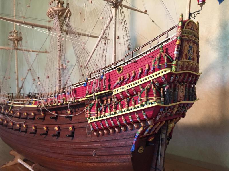
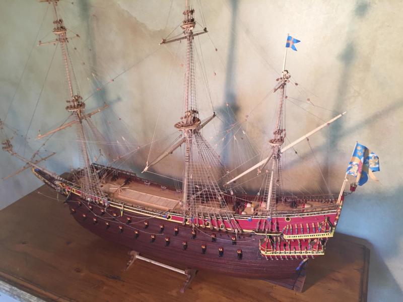
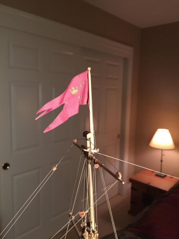
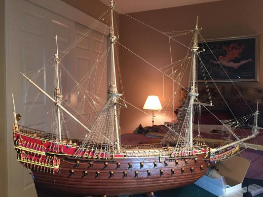
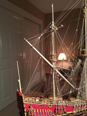
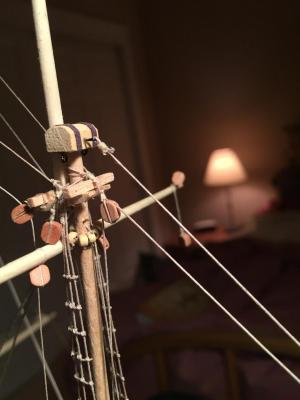
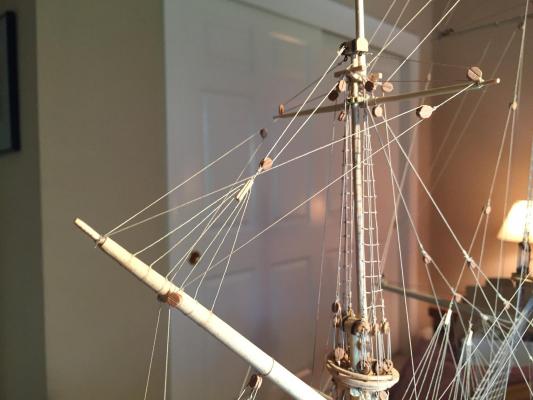
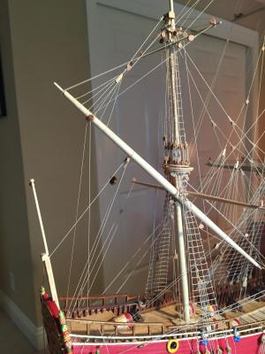
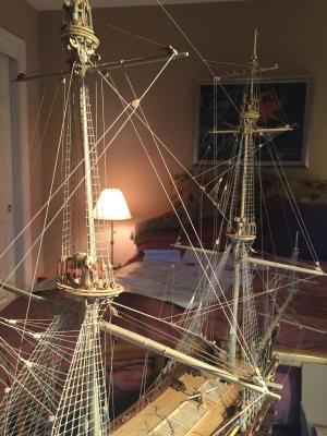
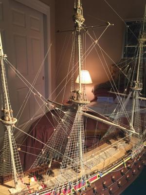
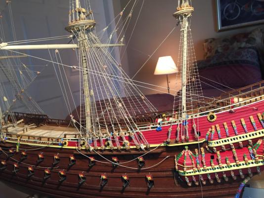
Greetings all - it's been a while, and I realized I forgot to post pictures of the finished model with all flags flying, so here are some photos. With that I'll sign off. It's been a great project, many thanks for all the encouragement and assistance!


- 249 replies
-
- 9
-

-
- billing boats
- vasa
- (and 1 more)
-
Question for the group: any recommendations for people who make display cases? The company that was making mine is proving flakey...
- 249 replies
-
- 1
-
-
- billing boats
- vasa
- (and 1 more)
-
Jan - I used the image as posted. It's a JPG as converted from a vectorized (SVG) file. Vector graphics are easier to manipulate than raster graphics, but once you're done, you can just export to a JPG as I did for the above post.
- 249 replies
-
- 2
-
-
- billing boats
- vasa
- (and 1 more)
-
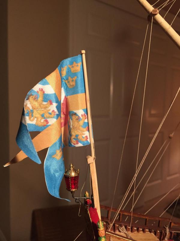
Oh, and in response to your question about the lantern - If I recall correctly, it's from Amati, 23mm size.
- 249 replies
-
- 2
-
-
- billing boats
- vasa
- (and 1 more)
-
Yes: http://www.amazon.com/Jacquard-Fabric-Silk-Sheets-pack/dp/B000BGSZ1E. Any ink jet printer will work. I waited 24 hours to make sure it was completely dry, then just make sure you keep it away from solvents.
- 249 replies
-
- 3
-
-
- billing boats
- vasa
- (and 1 more)
-
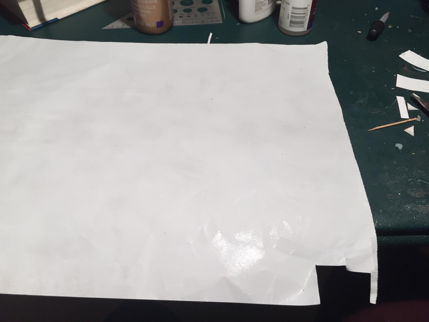
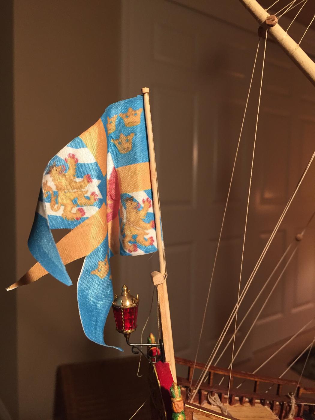
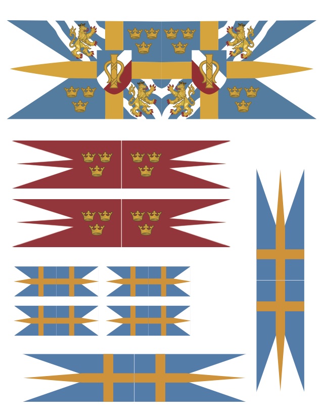
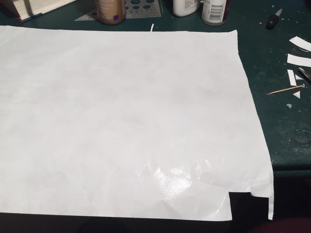
Well, I've finished the flags and alas before looking at the post above. They turned out pretty well though, and since I have the artwork in digital form, I can always go back and look at the build log above and see if I can improve things. So first I scanned the Corel artwork. Then I noticed the large flag is basically the Vasa royal arms, and I found a vectorized public domain image of the arms that was much nicer looking than the Corel version. My sister's a graphic artist, and she vectorized the remaining artwork, and mirrored it so I could fold each flag back on itself and have nice bright colors on both sides. Here's the artwork layout: Next, I printed the flags onto silk, using an ink jet printer. The silk is backed by paper so it feeds through the printer nicely. Then you peel off the paper and you're ready to go. The silk was fine enough that it printed through to both sides, but was much brighter on the outward face. Then it was time to experiment. First I had to deal with fraying on the edges. Fabric seam sealer dissolved the ink, so that didn't go well. Fortunately I had a pack of ten sheets of silk, and two copies of all but the largest flag per sheet, so the failures weren't a problem. Next, I tried diluted white glue, which ended up working quite well as long as I applied it before I peeled off the paper backing on the silk sheets. I then cut out a flag, peeled off the paper, folded it back on itself, and glued using more diluted white glue. So far, so good. Then once that was dry, I soaked the flag in water, applied more diluted white glue, and bent it to shape. The result was OK, but messy to do, and it was hard getting the flag to hold its drape while the glue was drying. So I decided to try another approach and see if it worked better. I took a sheet of aluminum foil and sprayed both sides with flat white paint suitable for metal: Then I cut a piece to match the flag. I didn't cut the swallow tails - I wanted to do that once everything was together. Then I folded the flag over the foil and glued it with slightly diluted water-based craft glue. Once it was dry, I trimmed the flag to size and ended up with something slightly heavier than plain silk, but not by much. And importantly it would hold bends without starch or glue! Then it was just a matter of creating furls that I was happy with and mounting the flags to the flag staffs. I used the same thread that I used for seizing rigging, glueing it to the inside of the fold at the leech of the flag. I'm pleased with the result. The silk has a nice texture and a very slight sheen. At any rate, the result is much better than I'd get using the kit flags. Here are two of the flags mounted: And with that, the ship is finished! I'll post a few more photos of the completed ship shortly. I'm still waiting for the display case to be finished - should be done in a few weeks.

- 249 replies
-
- 9
-
-
- billing boats
- vasa
- (and 1 more)
-
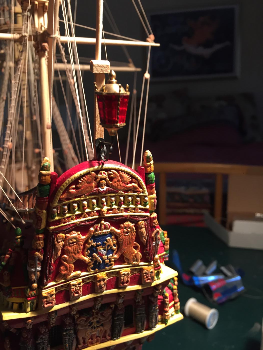
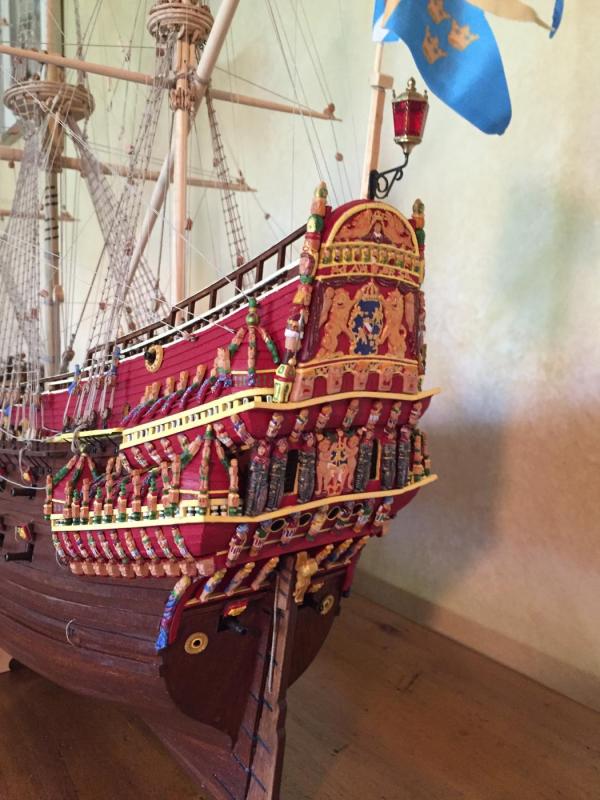
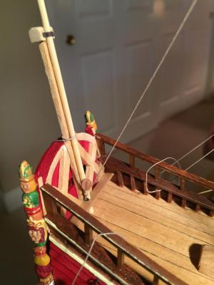
I'm still in flag limbo. I did find a nice stern lantern which I mounted to the transom: The Corel Vasa flags showed up a few days ago. They are better quality than the Billings ones, and more interesting looking. Printed on both sides, and on lighter weight fabric that isn't so water-repellent. But I'm still having problems getting them to furl, and the artwork has black outlines around the design elements on two of the flags, giving them a cartoon-like quality. So I scanned the flags onto my computer, and I'm getting the images vectorized so it's easy to clean them up. Then I'm going to try three approaches. First, I bought some sheets of ink-jet-printable silk, attached to paper with an adhesive backing. The silk is much lighter weight than the Corel flags. I'm going to print a double image of each flag onto the silk, fold it onto itself, then see if I can get the result to hang naturally. If that doesn't work, I'm going to fold the silk around some aluminum foil primed white. That'll make the result thicker and heavier, but it should be bendable. If that doesn't work, I'm going to try the same white-primed aluminum foil trick, but print onto decal film and attach the decals to each side of the foil. If that doesn't work, the Vasa enters its display case sans flags. A man's gotta know his limitations. The base for the display case is being built, but likely to take a while.

- 249 replies
-
- 6
-
-
- billing boats
- vasa
- (and 1 more)
-
Installation of the flags is not going well. First, they are only printed on one side so the other side doesn't look good. Second, it looks like they are made of some sort of synthetic material that is resistant to water. Finally, the material is somewhat stiff. The combination makes it very difficult to get them to hang in a natural furled manner. I've tried simply dampening them with dilute white glue, but the mixture just beads up. I also tried taking some thin aluminum from a soda can, bending it, and gluing the flags to it. The material adhered to the aluminum, but as soon as it was dry and I lifted it off, it promptly lost its bends. All in all very frustrating. I've ordered a flag set for the Corel Vasa, since it's the same scale and my first model was a Corel and had nice flag material. The Corel flags are also more interesting looking than the Billings ones. So when that shows up I'll try again. Otherwise, no flags for the model.
- 249 replies
-
- 1
-
-
- billing boats
- vasa
- (and 1 more)
-
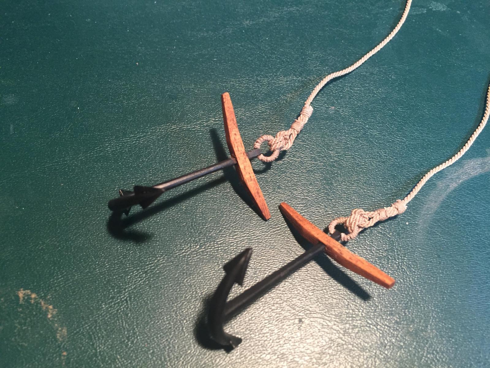
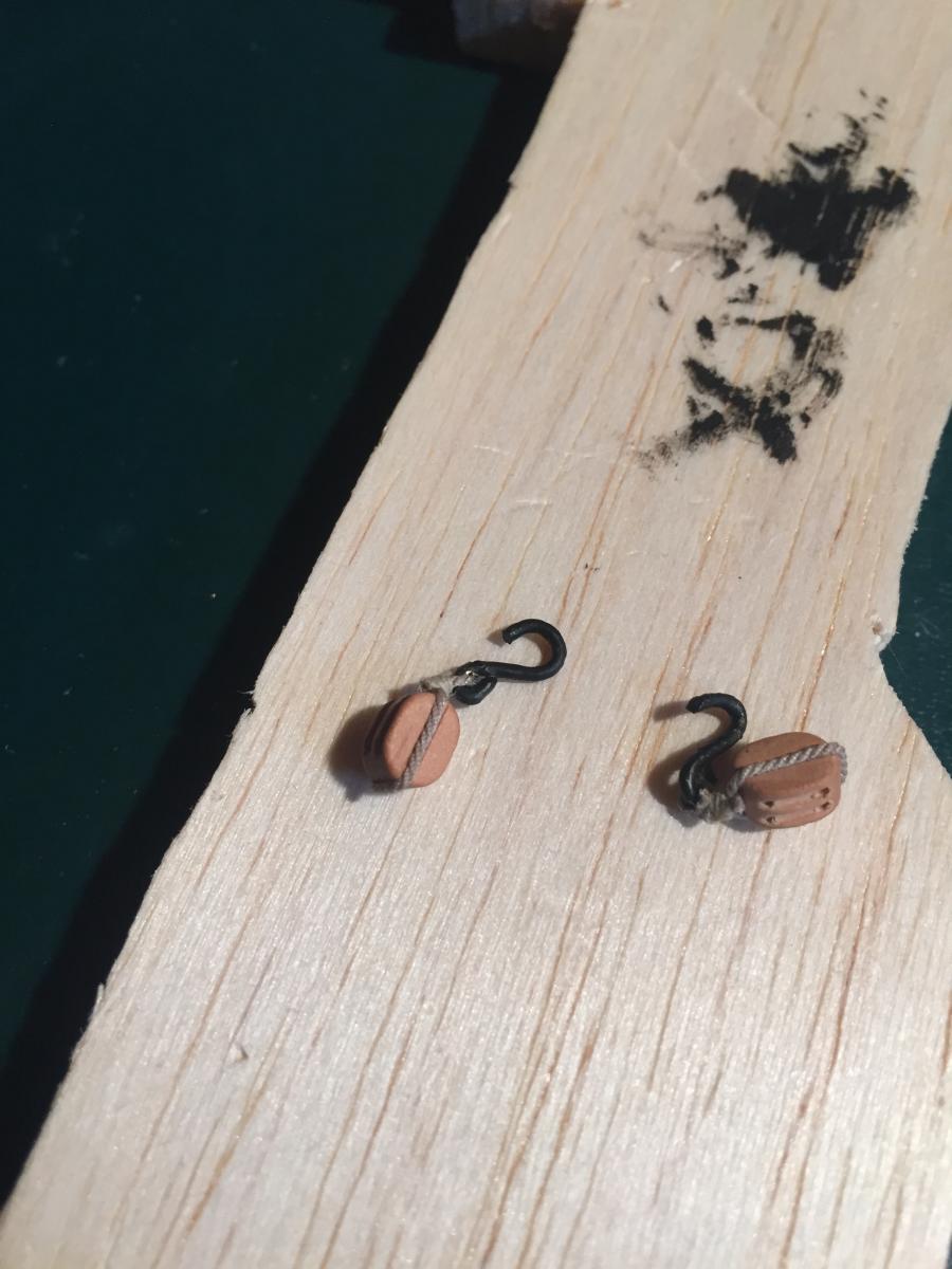
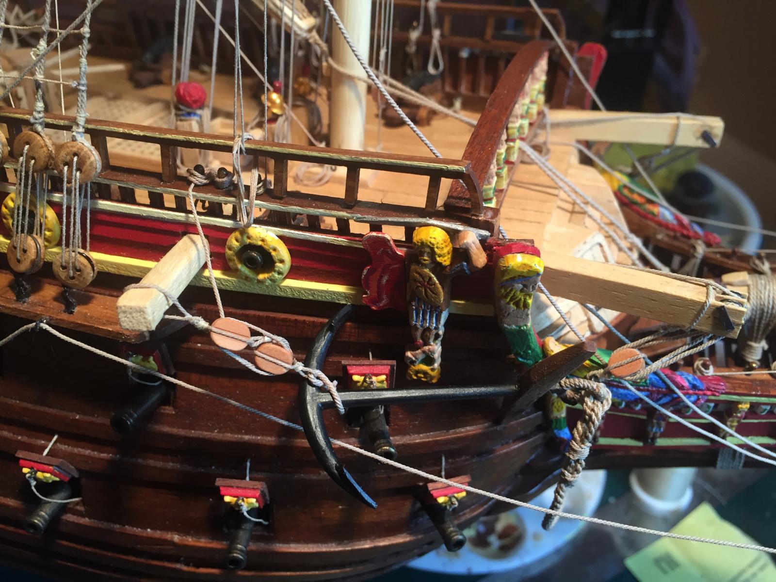
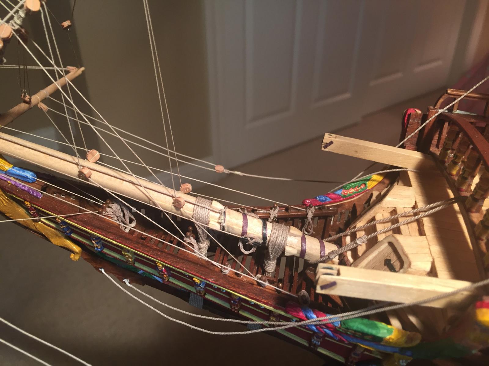
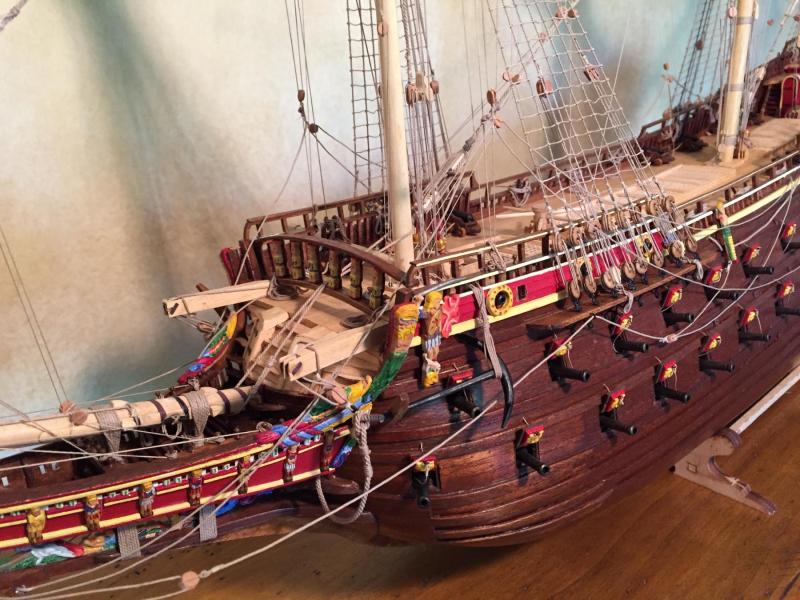
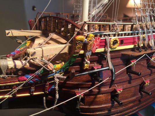
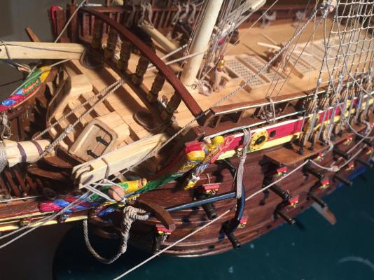
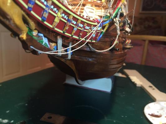
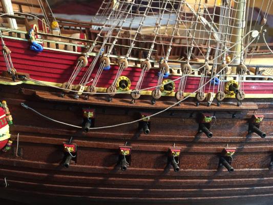
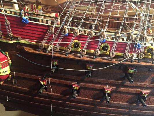
The anchors, like so many aspects of this model, were more difficult than I thought they would be. The original ship appears to have had several anchors, all of different sizes, and it's not clear which were deployed when the ship sank. The kit provides two identical anchors, so that's what I used. The anchors and stocks are both made of black plastic. Cleaning up the flashing and painting the anchors flat black makes them look fine, but simulating wood using paint doesn't turn out well, so that meant scratching a pair of stocks. None of the pictures I could find showed iron bands around the stocks, so I left them off. The anchors were pretty generic and didn't look like the originals, so I reshaped them, particularly the flukes, so they looked a little closer to the real thing. The kit plans don't say anything about anchor rings either, so I scratched them from wire and puddened them with rigging line. Then I seized a cable to the ring with an anchor bend, using the heaviest rigging line I had, which was about 1.5mm diameter. The result was pretty good, certainly much better than if I'd used the plastic anchor stocks: Then I needed to make a pair of cathead blocks. The 1:10 model has some decent photos, and they show an iron strop around a double block, with a hook on one end. I couldn't make the iron strop look good, so I went with rigging line. The hook was just wire, bent into shape and painted black: Here are a couple of pictures of the port anchor installed. I ended up glueing it to the hull at one fluke edge and one end of the stock, otherwise it flopped around annoyingly. The bottom of the anchor is seized to a frame; the top is rigged to the cathead with the cathead block, the hook going around the anchor ring. I couldn't find good detailed photos of the 1:10 cathead rigging, so I took my best guess. The free end of the line winds around the front railing a few times and then is left in a coil. The starboard anchor was more complicated because of the anchor davit on that side. I rigged the top of the anchor just like on the port side, but the bottom is attached to the bottom of a pair of blocks, the top block in turn being attached to the davit. The free end of the rigging is looped around a belaying pin: And finally, a picture of the anchor cable. It's pretty thick, so I needed to soak it in water for a bit to get it pliable enough to hang properly. After brushing it with diluted white glue and letting it dry, it hung down nicely. Wow, getting very near the end now. The display case is ready for pickup, and I need to install the flags, clean up any final bits and pieces, and I'm done! The flags look to be tricky - the material is somewhat water-repellent, which will make wetting and glueing difficult.


- 249 replies
-
- 9
-
-
- billing boats
- vasa
- (and 1 more)
-
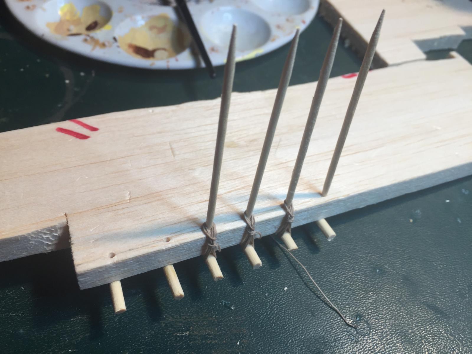
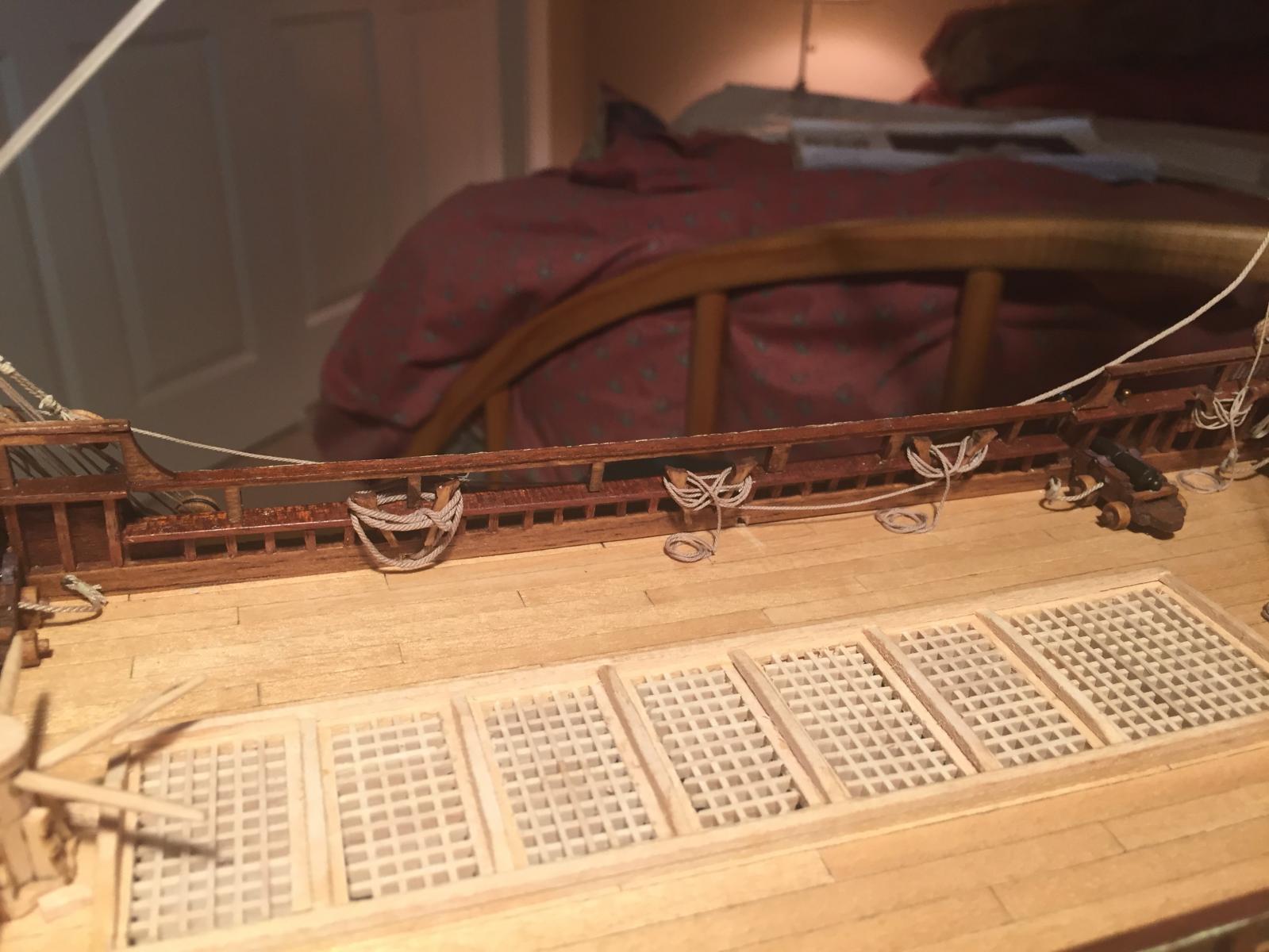
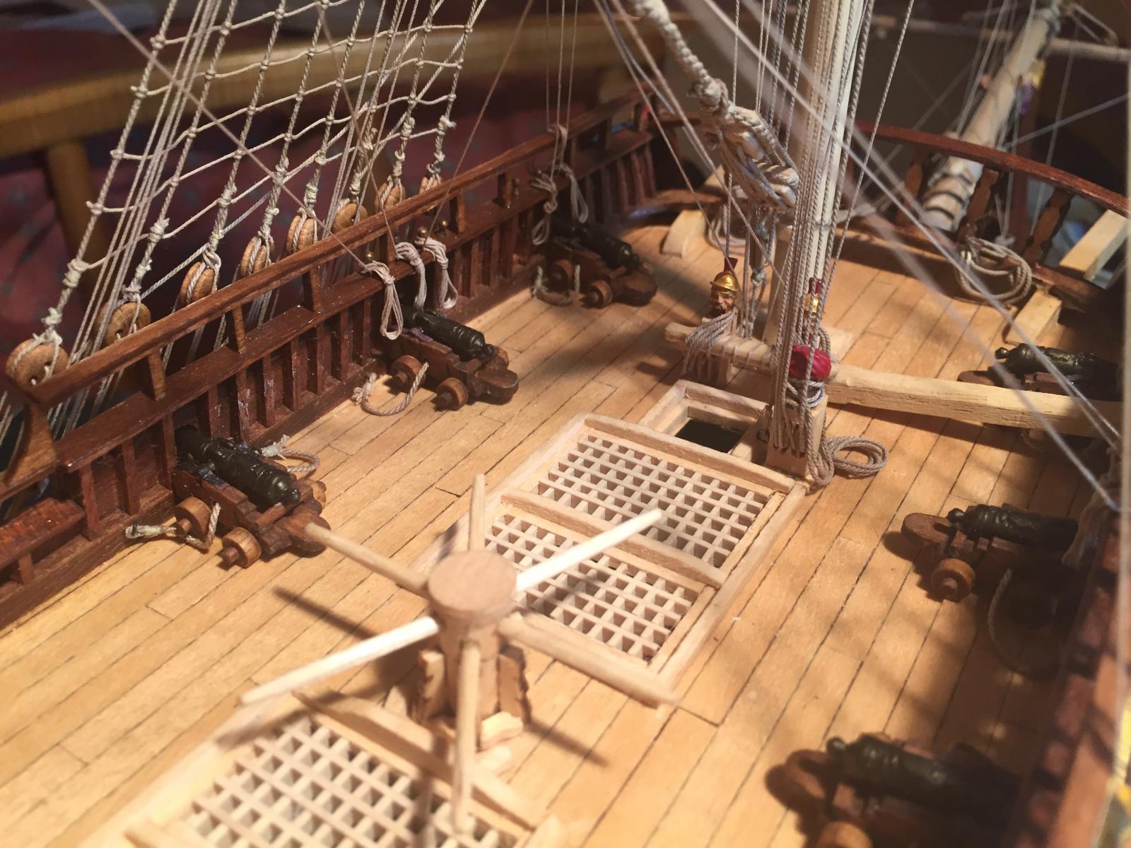
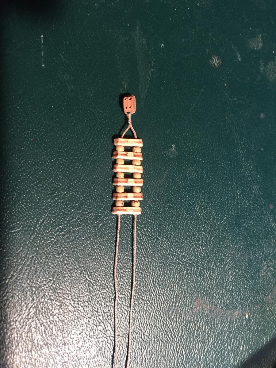
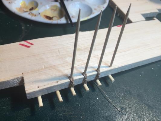
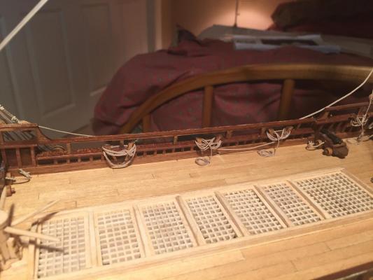
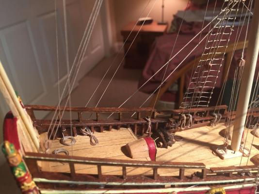
So on to making rope coils. I made more or less three different kinds. One was just a basic coil on the deck, which I made by winding rigging line around a plastic cylinder of the right diameter, brushing the result with diluted white glue, and letting it dry. Then slip it off the cylinder, trim the line and you're ready to install. Installation was mostly putting a few tiny drops of CA glue on the coil and gently pressing the coil onto the deck. I did this for lines belayed to deadeyes in the tops, plus some of the lines belayed to the bitts behind the fore and mainmasts, and the braces belayed to frames on the poopdeck. Here are some examples: The second kind was more difficult because it had to be done in place. This was for coils around the kevel bitts. I did two kinds, one just wrapped in a series of loops around the bitt, then down to a coil on the deck. The second was a series of figure eights around the bitt, then down to a coil on the deck. This involved brushing the line with water to get it nice and supple, then winding it around the bitt, then brushing with diluted white glue, then coiling, and brushing the coil with glue. Doing this in place was very fiddly, but I couldn't think of a better alternative. Here's a photo of the kevel bitts with their coils: And finally, coils for belaying pins. This was straightforward but tedious since there are so many - I lost count at 40 or so. I made a simple jig on a piece of scrap balsa, consisting of dowels below, and removable toothpicks above. The height between the dowels and the base of the toothpicks was 10mm, which was a good universal height for the coils. I wound figure eights, then looped the end of the line around the middle of the figure eight, brushed everything with glue, and let dry. I did six at a time, then carefully dislodged them from the jig and dropped them over the belaying pins with a little CA glue on the base to hold in place. Most were pretty easy to get into place, but some were located in hard to reach spots. I didn't use the kit's belaying pins because they were too large for my liking. Instead I bought some thinner Amati ones in bronzed metal. I painted them with a brown wash to tone down the metallic sheen and the result looked pretty good. Here's the jig: And the coils: With, it's on to the anchors.


- 249 replies
-
- 8
-
-
- billing boats
- vasa
- (and 1 more)
-
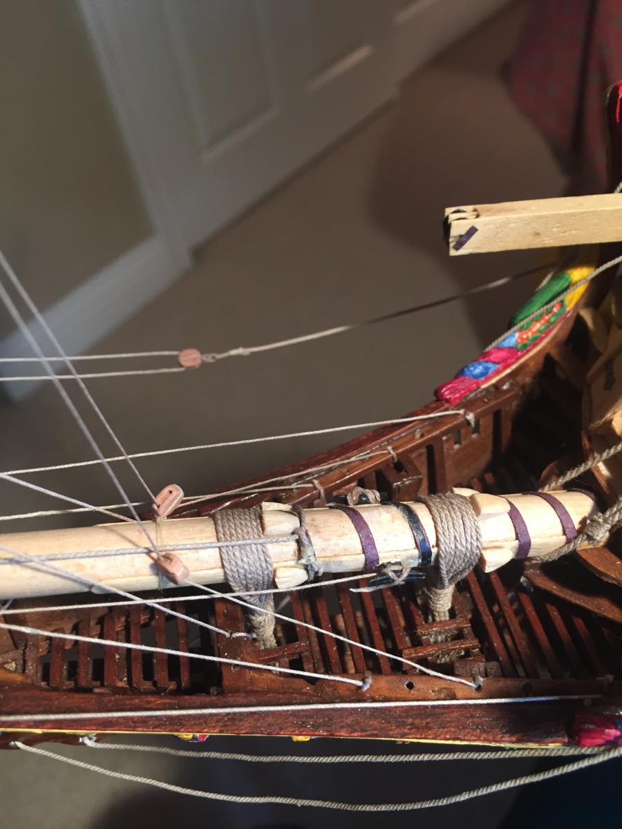
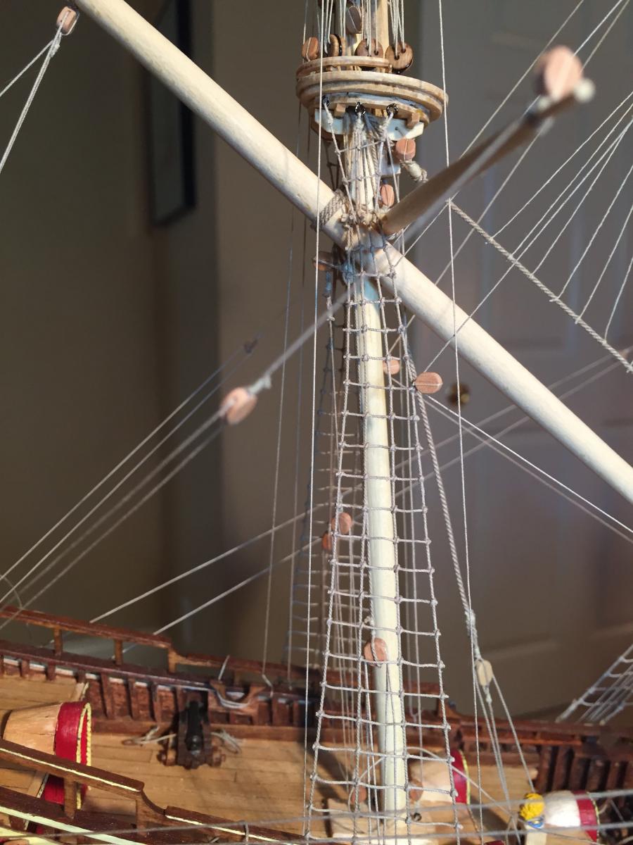
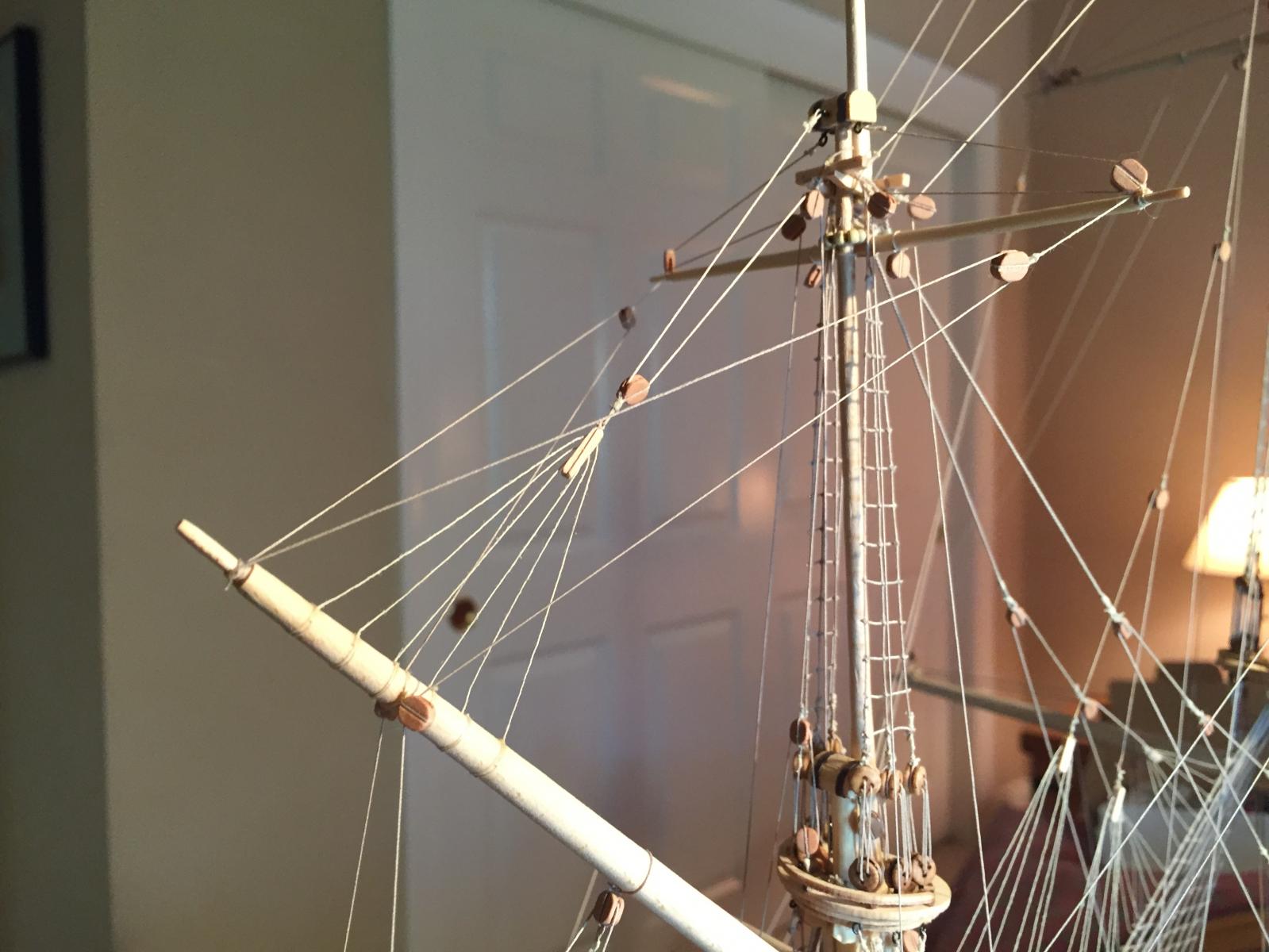
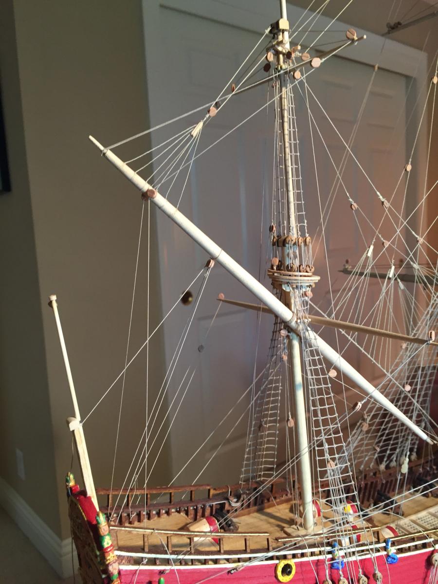
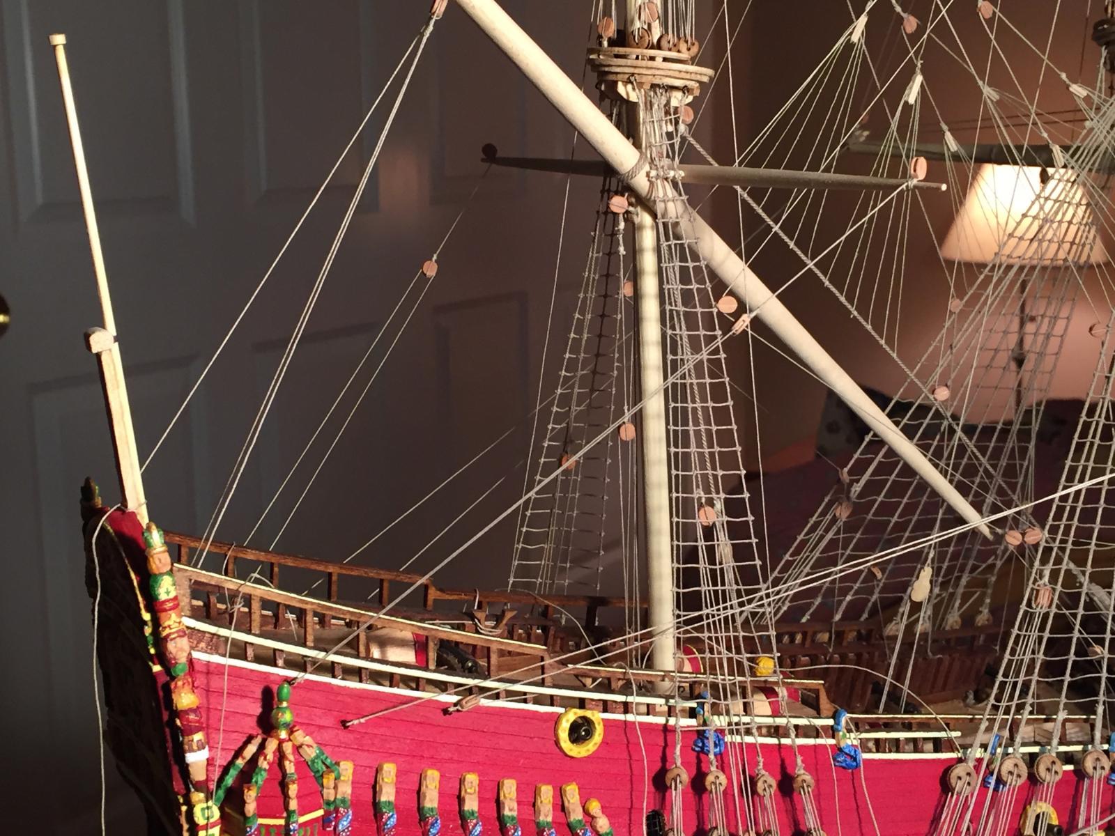
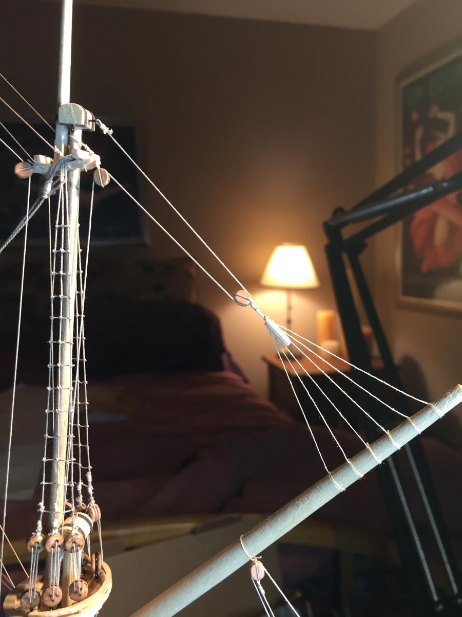
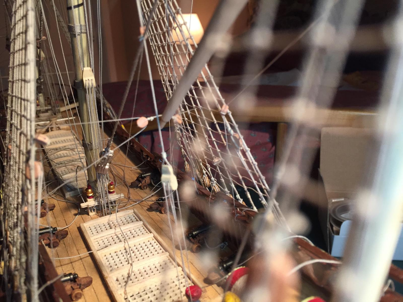
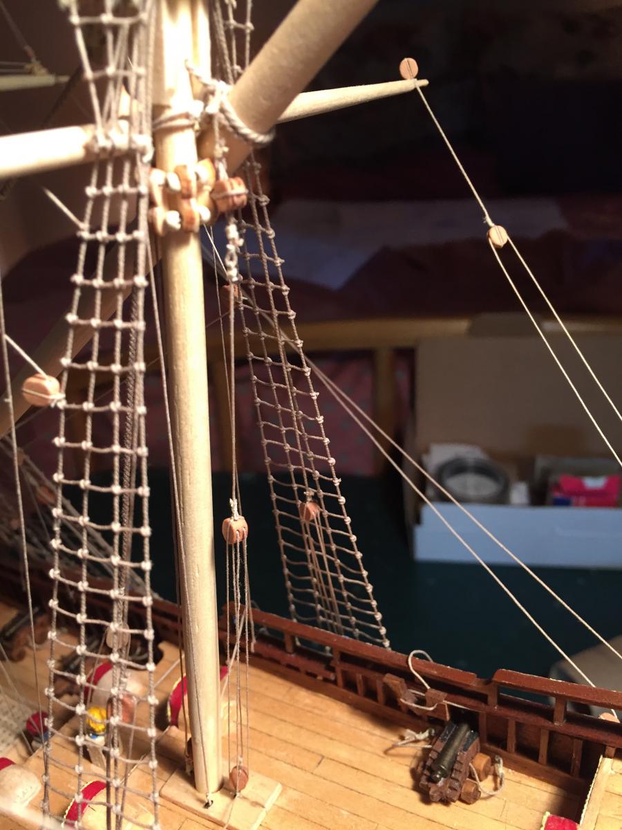
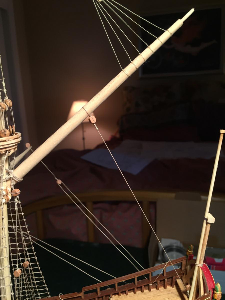
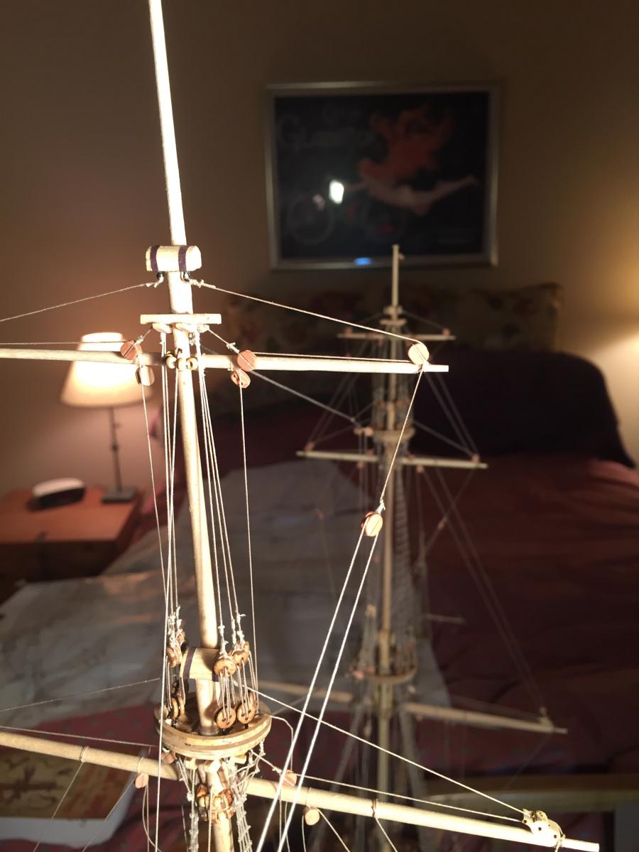
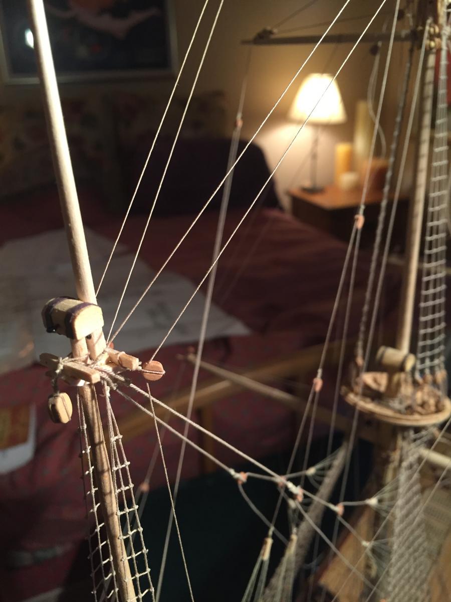
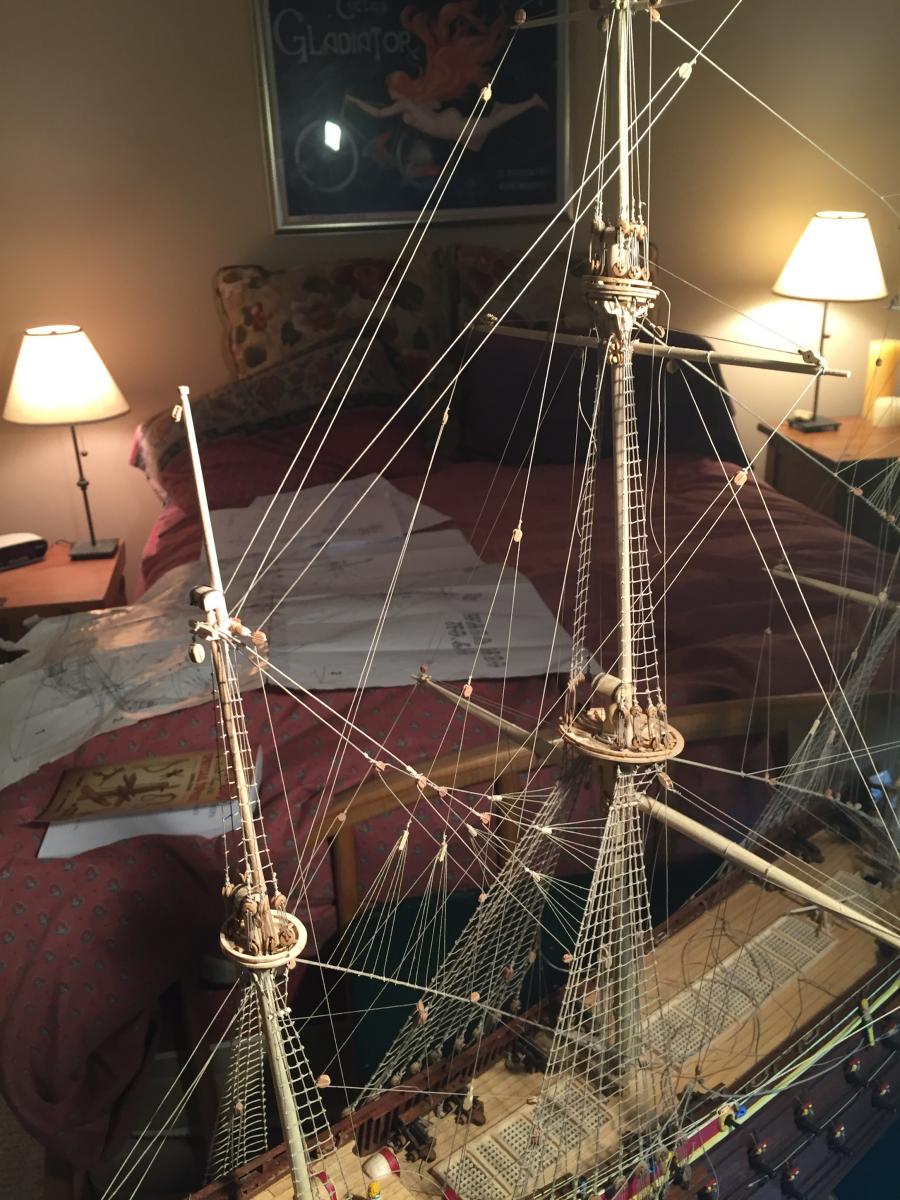
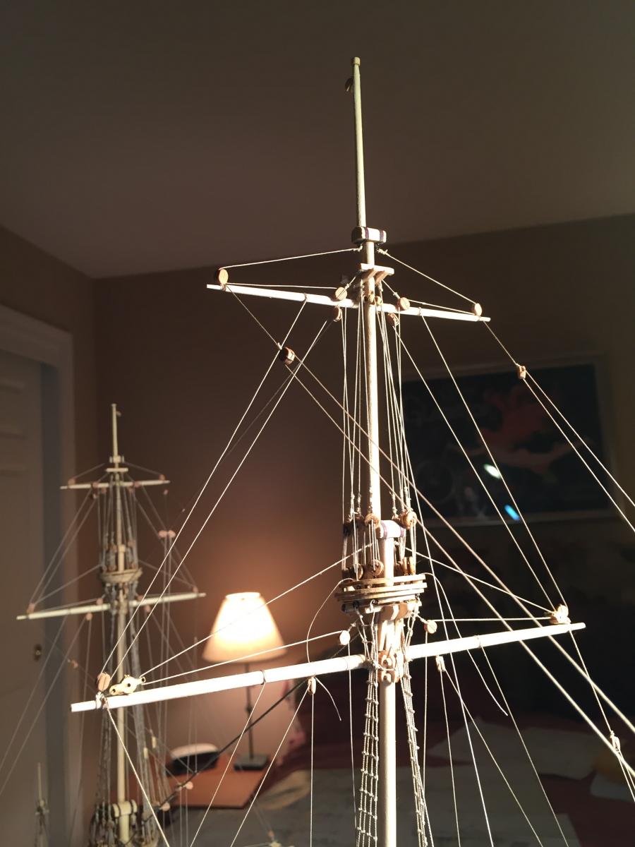
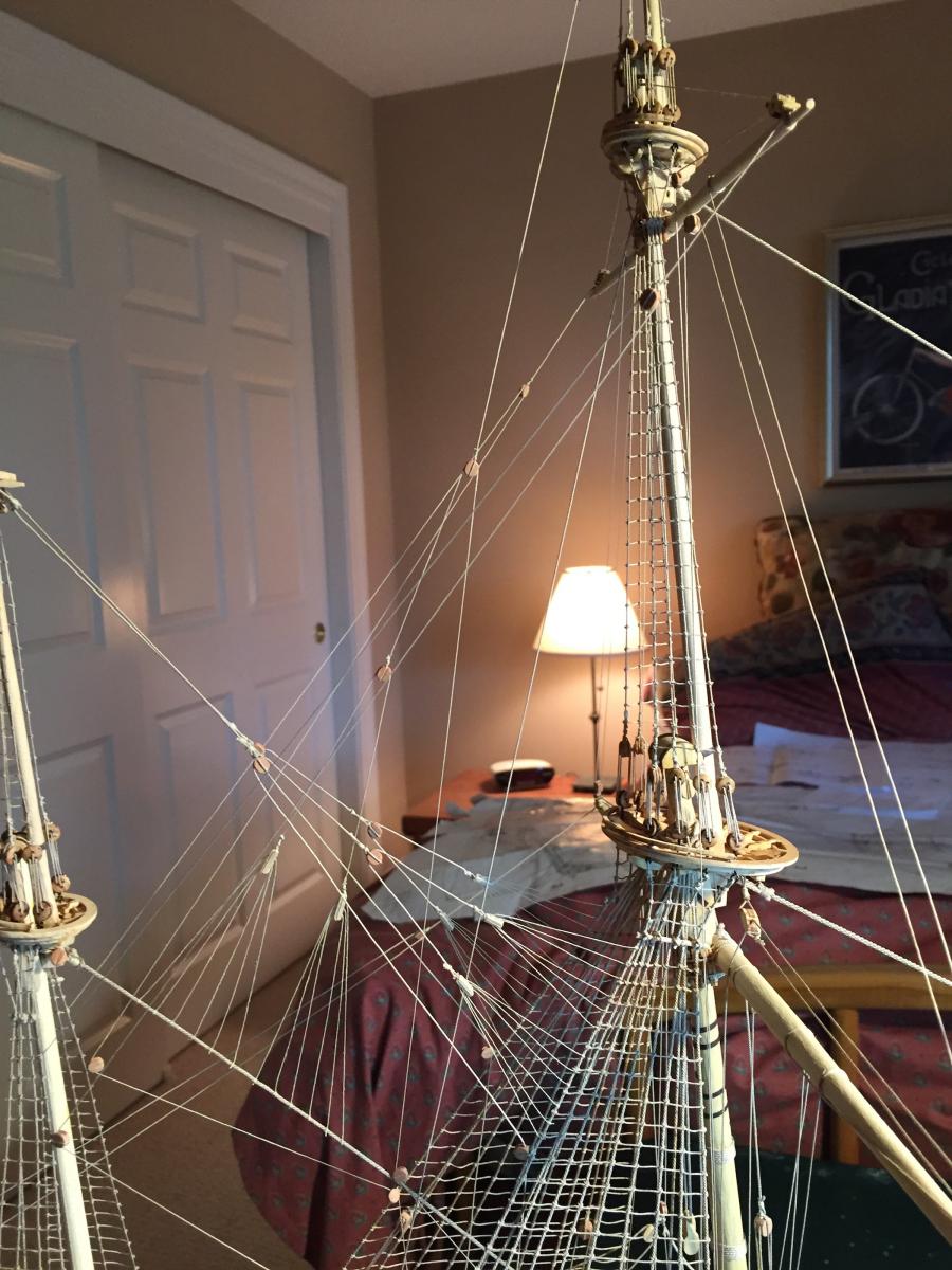
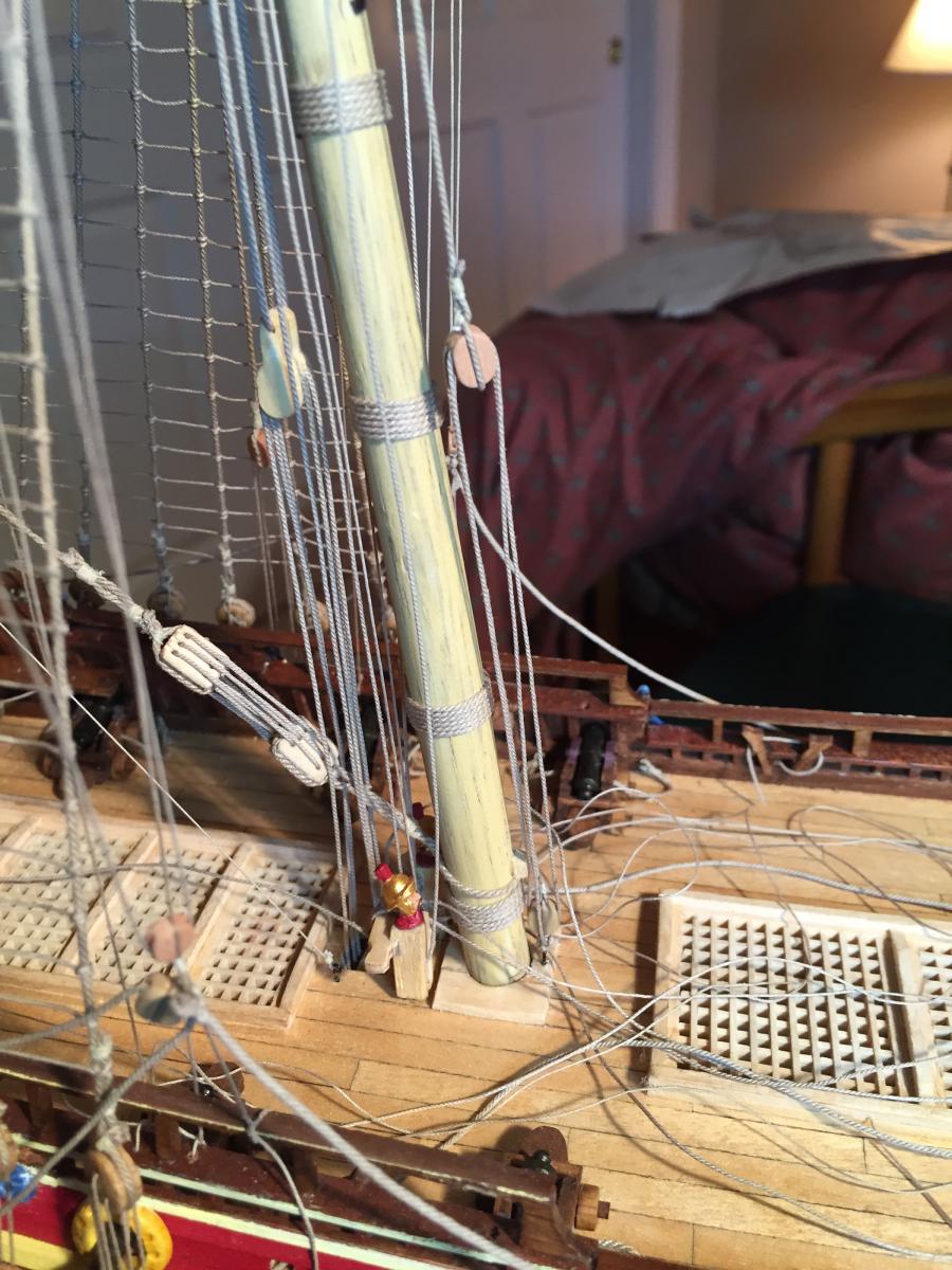
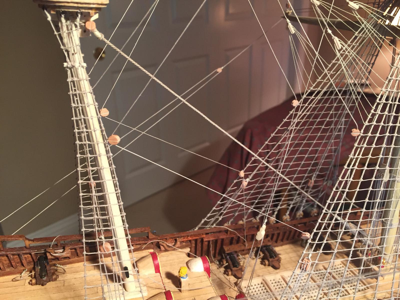
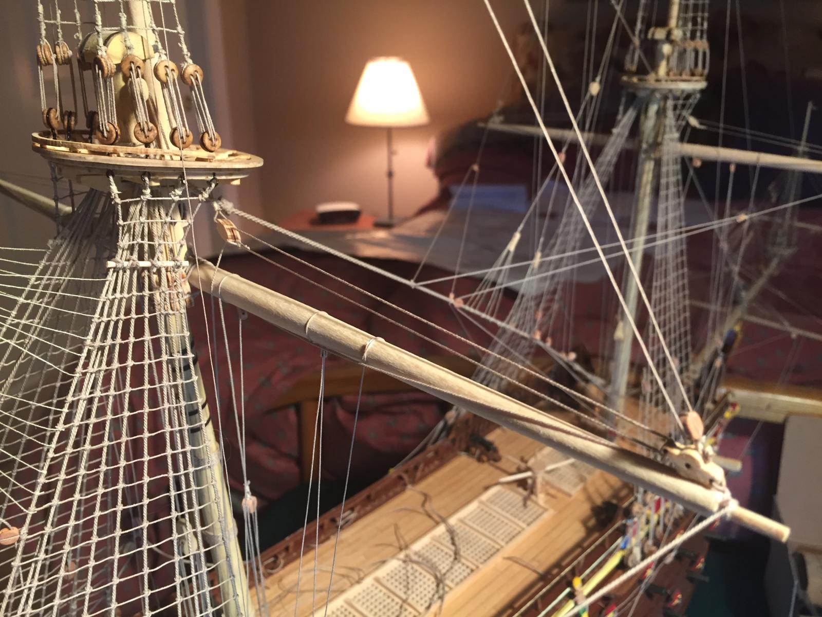
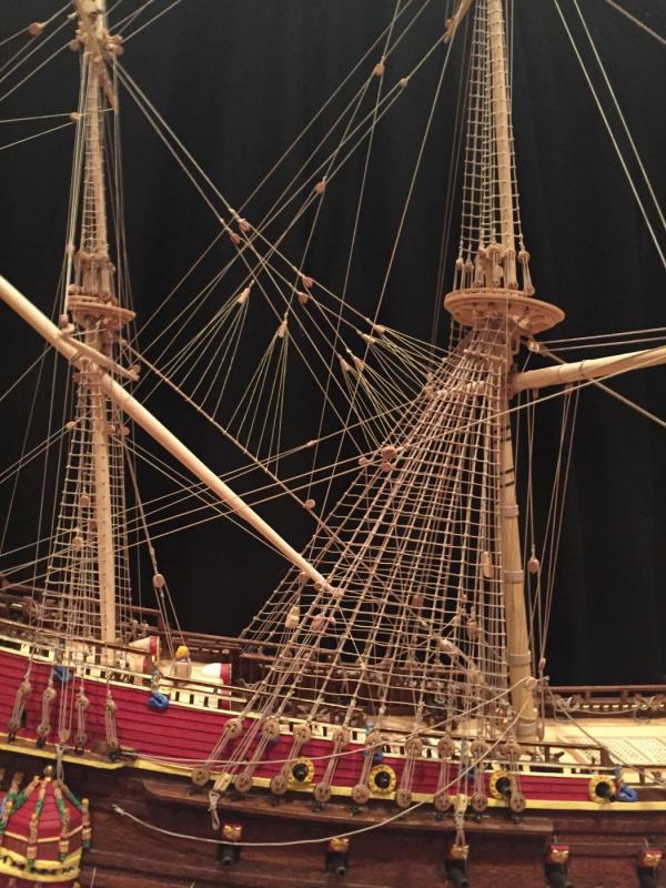
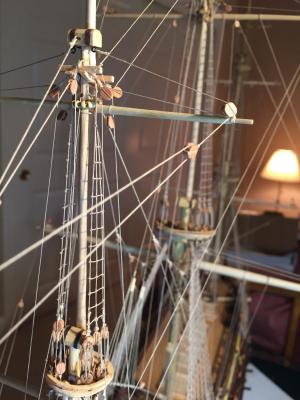
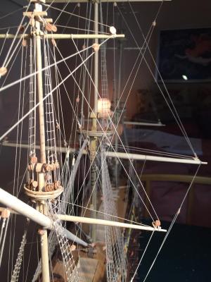
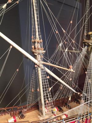
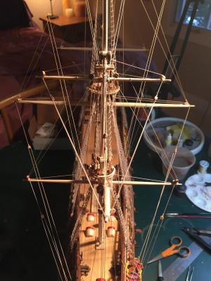
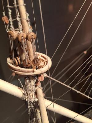
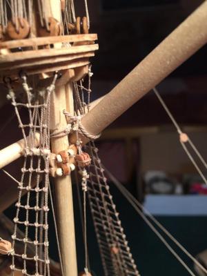
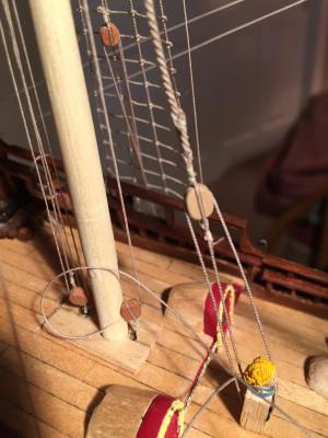
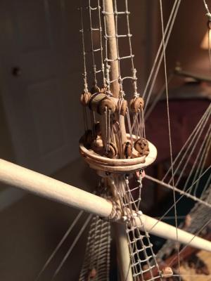
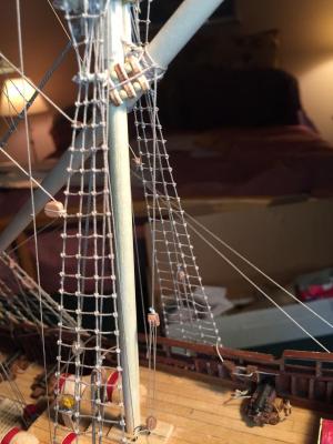
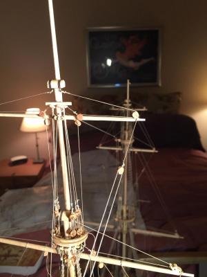
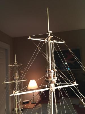
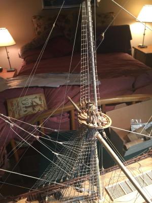
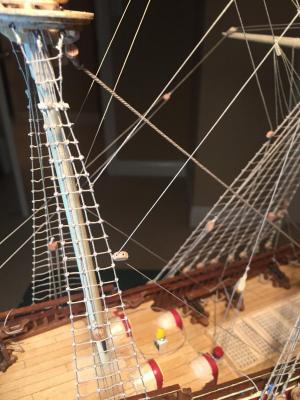
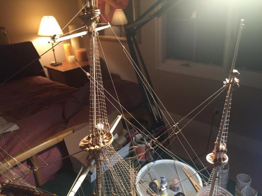
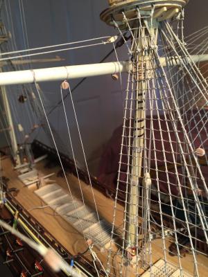
I do feel pretty good! When I started the project 2+ years ago I wasn't sure if I had the skills to do it justice. I'm pretty happy with how it turned out - I feel like I improved my skills and enjoyed myself, and you can't beat that. Some more small tweaks to the rigging. The kit plans call for three cleats on the bowsprit, to which the sprit halliard, sprit top halliard, and fore topgallant stay attach. Looking at the museum plans, as well as the 1:10 model, there are only two cleats, and the stay looks like it loops around the bowsprit. That also tallies with one of my books, so I decided to remove the cleat and re-rig the stay. Then I went back and looked at way the museum plans and the 1:10 model route the sprit sheet. It was slightly different from the way I did it, which if I remember right was based on the kit plans. The kit plans routed the sheet to a sheave in the bulwarks a bit aft of the large sculpture through which the main tack is routed. The museum plans and the 1:10 model route the sprit sheet to one of a pair of sheaves farther aft. They carry the sheet forward to the same kevel bitt, it's just that the sheet's somewhat longer. I liked that look better, so I redid it. You can see the profusion of sheets and tacks in this picture - I still need to gently tweak the lines so they hang properly, but they look pretty good. Then there was more messing with the main sheet. The kit has a bunch of pinrails that are mounted to the bulwarks in various places, including just forward of the doors to the helmsman's cabin. Apparently none of these pinrails are supposed to be there, so I removed them all. In particular, the ones by the helmsman's cabin doors were more likely a kevel bitt around which the main sheet was belayed. I'd run the sheet behind the main channels, to a kevel bitt farther forward. So I fabricated a new pair of kevel bitts, installed them where the pinrail was, and moved the sheet back a bit, as you can see in the following photo. I found I had a number of parrel beads left over after rigging all the yards, so I made up a parrel for the sprit topmast. The kit just specifies a sling, but all the other sources agree there's a parrel there. It looks like it should have ribs and two rows of trucks, but I couldn't see how to make that look good at scale, so I went with the same single row that the topgallants and mizzen topsail yard have. And the finished rigging! It's much easier to see all the complexity without the sails, although the model looks less realistic. I don't think I could have done a good job with the sails anyway. I'm going to spend a tedious chunk of time making rope coils now, so no postings for a bit.


- 249 replies
-
- 10
-
-
- billing boats
- vasa
- (and 1 more)
-
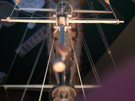
Thank you all for the positive feedback. This build has been a great experience - lots of new stuff to learn. Here are the lifts for the mizzen topsail. The kit plans are odd here - the lines seem to start at the end of the yard, then travel inward to pendant blocks and down to the deck. All the other sources route the lifts like the other yard lifts - from a ring bolt at the mast cap, then out to a block on the end of the yard, back in to the pendant, and down. So I ignored the kit plans. The clewlines are run exactly like the other topsail clewlines - from the yard, down to a clew block at the end of the crossjack yard, back up to another block and is then belayed at the caprail. The sheet has a stop knot in one end, and runs through the clew block, inward to a pendant block at the mizzen top trestles, and is then also belayed at the caprail. The museum plans show the lifts belayed at the mizzen top, but the 1:10 model and Clayton's model show the lifts belayed at the caprails. I took the lines down to the caprail, mostly for some consistency with the other topsail yards. The only difference is that the fore and main mast have bitt rails where you can belay the lines, and there isn't one for the mizzen. Here's a photo of the clewline, lift, and sheet lines and where they are belayed. Depending on how you locate the lift pendants under the mast cap, you might have to run the line in front of the crossjack yard; if you install sails, that may cause you some problems. Here's an interesting overhead view of the mizzen topmast cap and the profusion of pendants sprouting from it. One for the mizzen yard lift, two for the topsail lifts, and two leader blocks for the main topgallant braces. And an overhead view of the mizzen topsail rigging. And finally the mizzen running rigging all in place. Now I have to go back and make some minor changes to various parts of the running rigging that I don't like. Then it looks like the only remaining tasks are rope coils and belaying pins, anchors, and flags. I've already ordered a plexiglass box for the model, but I need to find a nice wood base for it. The case is huge - almost four feet long, 1 1/2 feet wide, and almost 3 feet high, so finding a place to display it is going to be challenging.

- 249 replies
-
- 5
-
-
- billing boats
- vasa
- (and 1 more)
-
More beautiful detail. The tackle pendants were the first rigging elements I installed on my model, and I relied on the (incorrect) kit plans; once I figured out they were wrong it was too late to add the hooks and extra blocks.
-
On to the mizzen topsail yard. The tie is pretty simple: a loop around the yard, up through a sheave in the mast, then terminating in a block. Unfortunately it's not clear from the kit plans, museum plans, or models exactly how the halliards are rigged. The most logical approach seemed to me to have the halliards running from a becket in the tie block, down to a block attached to a ring bolt on the mizzen top, back up, then belaying at the foot of the mast or the caprail. Fred Hocker agreed, and suggested that either belaying point was reasonable, although there is no evidence for belaying furniture at the foot of the mast. I couldn't find a way to run the halliard to the foot of the mast without fouling on the mizzen yard, so I ran it out to the caprail. Parrels were straightforward - no ribs, just trucks, and no truss tackle. The kit plans route both the crossjack yard and topsail braces forward to leader blocks on the mainmast shrouds. The museum plans, the 1:10 model, and Clayton's model all route the braces back toward the transom. The topsail braces start at the end of the mizzen yard, then go to the brace pendants, back to leader blocks on the mizzen yard, and then down to a belaying point around a frame below the caprail. Here's a close up view: And a view of the braces in context. You can also see the mizzen topsail halliard running down to the port caprail.

- 249 replies
-
- 6
-
-
- billing boats
- vasa
- (and 1 more)
-
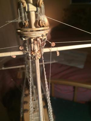
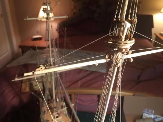
Thanks for the compliments. I'm very happy with how it's turning out, although I'm starting to look ahead and wonder how I'm going to be spending my time when the model's done. This has been a big part of my life for over two years now. Here's the crossjack yard. It's pretty simple, which is a good thing, since the kit plans, the museum plans, and the 1:10 model are incredibly cluttered in this area and it's hard to see much of anything. According to my books, the crossjack yard was typically not moved, so there are no parrels or tie. The yard is held in place by a simple sling around the outside of the trestles, and the sling is run through a block attached to the yard. Clayton's model shows what might be a pair of jeer blocks, but it wasn't clear how they were rigged, so I went with the books. Instead of a parrel, there's an assembly similar to that of the bowsprit. It's hard to describe; hopefully the photos make it clear. One loop is seized around the yard, then brought around the back of the mast, looped and seized on the other side, looped back around the mast again, run through an eye, and seized back on itself. Then the braces. The kit plans run these forward toward the mainmast, but every other source runs them back toward the transom. It's hard to tell whether both ends were seized around frames below the cap rail, or whether one end was seized to a ring bolt and the other to a frame. I chose the latter because I liked the look better. The only remaining rigging on the crossjack yard is the mizzen topsail sheet, which can't be rigged until the topsail yard clewlines are in place. That's next. Ten yards down, one to go!


- 249 replies
-
- 9
-
-
- billing boats
- vasa
- (and 1 more)
-
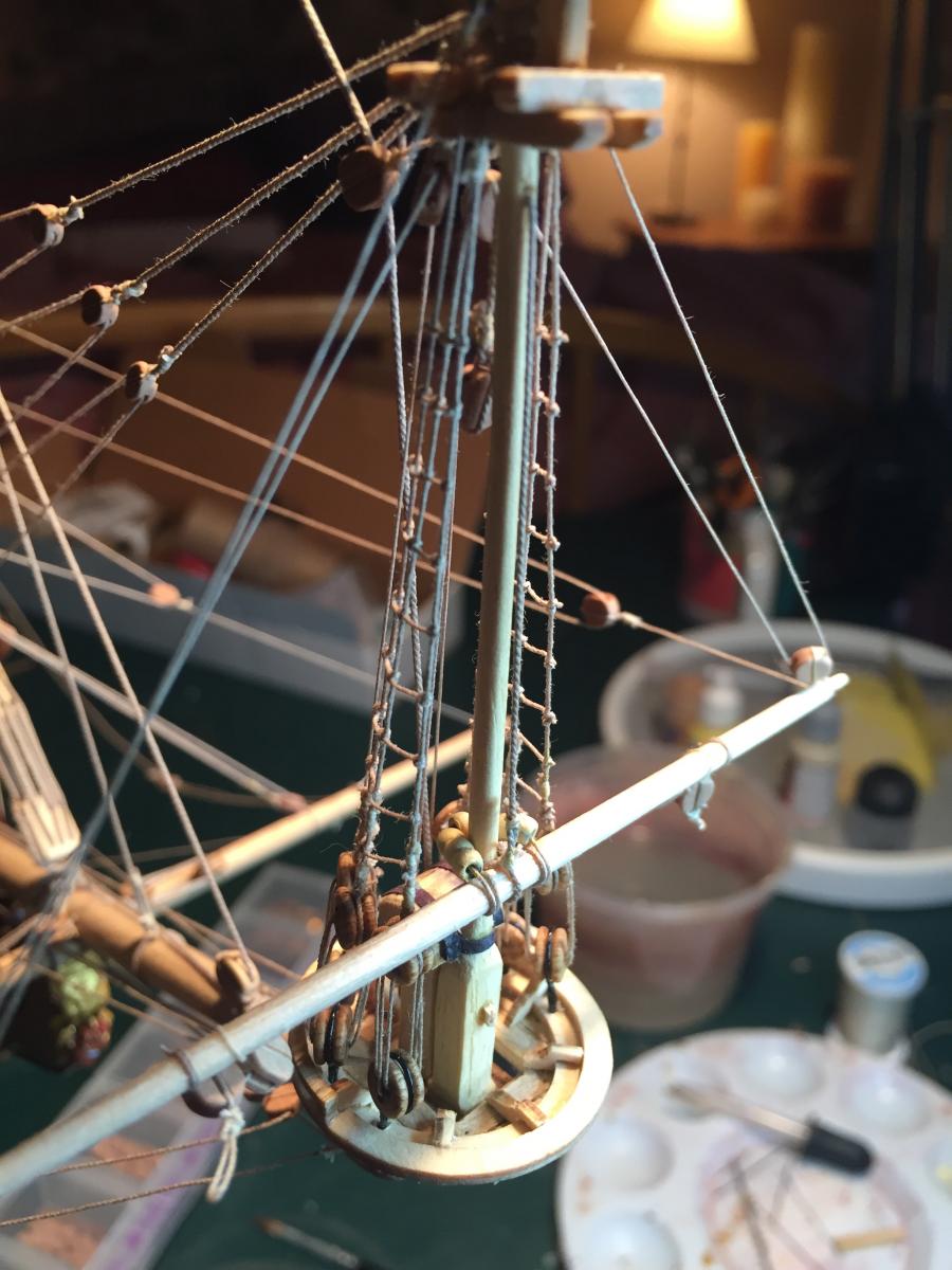
I decided I didn't like the way I set up the parrels on the mizzen yard, so I took another run at doing it the "right" way. I went back to the arrangement with the double block at one end: Then I wrapped the parrel around the mizzen mast. I did not run the parrel lines around the mizzen yard - I think that's what messed things up the first time. Instead, I brought the lines straight around and through the block at the end. Then I seized the two lines to the mizzen yard tie, per the description in Rigging of Ships in the Days of the Spritsail Topmast: Once the lines went through the block, I joined the ends together in a thimble and then attached the truss tackle block to that. Here you can see the truss tackle and its blocks, with the end belayed around the bottom block. Now I'm happy with the result. On to the mizzen yard lift. This was straightforward - the kit plans (mostly) agreed with the museum plans, my books, the 1:10 model, and Clayton's model, so that's good enough for me. The line starts from a ring bolt on the mast cap, then down to the yard, where there's another block, a euphroe tackle, and crows feet. Then back to a pendant on the mizzen mast, down through the top, and terminating at a ring bolt at the foot of the mast. The kit plans belay to the caprail, which would mean you'd run the line outside the mizzen top and hope that it didn't foul on it. I decided to go with the museum plans. Maintaining tension on the lift's crows feet is easier once you rig the mizzen sheet, since they counterbalance each other. Without a sail, there isn't a "correct" place to locate the sheet block, so I just attached it to the yard. Fred Hocker kindly gave me some very useful pointers on where the sheet was attached on the deck - there's a staple on the center beam of the transom, to which a block is attached. From there, the line can be belayed to that block or up to a location on the rail. He also gave some insight into how the mizzen top rope might have been routed. The museum plans and the kit plans don't show one, although one would be required. There's no capstan in the area, and the knighthead doesn't have an extra sheave for the top rope like the fore and mainmast ones do. His best guess is that there was a leader block at the foot of the mizzen mast, which would allow the top rope to run out to the weather deck, where a bunch of men could haul on it to raise the mizzen topmast. That's what I did in the photo below; still not sure where/how I'll terminate the line. And finally the mizzen yard "braces". The kit plans are vague about how the lines run, but the museum plans, the 1:10 model, and my books are clearer. Each brace has a standing end tied to a main mast shroud. From there it goes to a block on the yard, back to a leader block on the shroud, and thence down to the caprail, where it's belayed. This was surprisingly difficult to set up, just because there are so many lines in the way at this point. While I was wrestling with the braces, I managed to detach the main mast bitts from the deck. My fault for not pinning them when I initially installed them. That meant carefully undoing the lift and sheet lines, re-gluing the bitts, and re-attaching the lines. Fortunately the lines weren't trimmed yet. Now it's on to the crossjack yard...


- 249 replies
-
- 8
-
-
- billing boats
- vasa
- (and 1 more)
-
Thanks for the compliment, much appreciated. I'm very happy with Chuck's rope and his blocks. Both are way higher quality than what came with the kit. In fact, looking back on the build, I ended up ignoring a fair amount of the kit-supplied material. On to the mizzen yard. This was pre-tapered and the correct length, so I assumed it would be dimensionally correct. Unfortunately, once I got it mounted and rigged, I thought it looked a little "fat", measured it and discovered it's a little bit oversized from the plans. Why they bothered to taper it but not make it the correct diameter is beyond me. The dowel stock for the yards was really messed up in general - various pieces missing, other pieces too short. I'll live with the slightly oversize mizzen yard - too much trouble to remove it and start over. First, the tie and halliard. This was a little tricky for me - it was difficult to figure out from the plans and other sources how the tie was attached to the yard. The kit plans and the museum plans are very cluttered in this area, and I couldn't find good close-ups of the 1:10 model or Clayton's model. There are clearly two loops around the yard, but only one sheave in the mast, and it wasn't clear how that worked. Ultimately I ended up hacking something together that looked reasonable. The tie is supposed to be quite thick - same diameter as the mizzen stay. It passes through a sheave in the mast, then down the other side, where it's got an eye to which the tie's block is attached. From there, the halliards are run down to the aftmost knighthead. The parrels were also difficult, again because the plans were too cluttered to make out any detail, and I couldn't find good detail photos. The book Rigging of Ships in the Days of the Spritsail Topmast was helpful here. It notes that the mizzen parrels were designed differently from the others because the mizzen yard needed to be maneuvered differently. It described a layout that looks like the following: This seemed to tally with what I could make out of the museum plans and 1:10 model. Then the book describes the parrel ropes leading around the yard, back through the block at the end, finally being seized together into a loop to which the truss tackle is attached. All very complex. When I tried to install the parrel assembly I failed miserably - it just didn't look right. I ended up starting over and doing the assembly in exactly the same way as the other parrel assemblies, without the extra block at the end. It looks a little odd because of the angle of the yard, but not too bad. You can also see the truss tackle and its termination on the deck.


- 249 replies
-
- 3
-
-
- billing boats
- vasa
- (and 1 more)
-
Thanks for the compliment! I think adding sails does obscure the beauty of the rigging, but also makes the ship look alive. Whatever choice you make, you've built a beautiful model. The lifts are very straightforward and identical to the fore topgallant lifts. The standing end is attached to a ring bolt under the mast cap; it then runs out to a block on the end of the yard, back in to another block on a short pendant, and then down to the front lower deadeye, where it's made fast. The braces are less straightforward. The kit plans show no brace pendants, just a standing end attached to the yard. Each brace then runs through one sheave of a double block and disappears on the rigging plan, but is mentioned on the belaying plan. So I assume the line goes straight to the deck. The museum plans, the 1:10 model, and the two books I looked at are all in agreement, and differ from the kit plans, so I once again ignored the kit plans. The standing end of each brace is attached to the rear mizzen topmast crosstree. It then runs to the brace pendant, back to a leader block on a short pendant attached to the front mizzen topmast crosstree, and then down to the deck. Here you can see the standing end and the leader block. And the whole thing. Finally, the clewlines. These are again straightforward and just like the fore topgallant clewlines. Made fast to the topgallant yard, down to a clew block at the end of the fore topsail yard, back up to a block on the topgallant yard, and thence to the second lower deadeye, where it's made fast. And the mainmast rigging is done! I can't tension and trim the lines until I get the mizzen yard done, because it looks like there will be lots of fiddly work between the mizzen and mainmasts and I'm sure I'll snag a line or two while I'm working in there.


- 249 replies
-
- 3
-
-
- billing boats
- vasa
- (and 1 more)
-
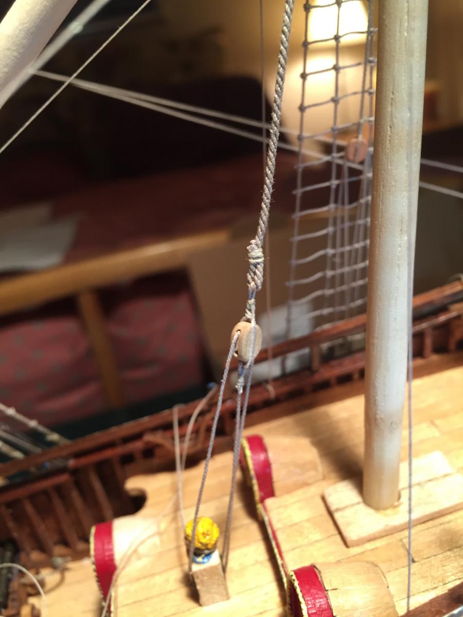
Just when I thought I was safe, I had to do the main topgallant tie and halliards. The kit plans are confusing here because lots of lines are crossing all over the place and they don't label them well. Fortunately the museum plans are a little clearer, as is the 1:10 model. The tie is very straightforward - loop around the yard, then through a sheave in the mast and down the other side, where it terminates in a block. Then things get complicated, with the usual arrangement of a pair of crows feet connected by a line run through a block at the end of the halliard. This was the most difficult piece of rigging so far, just because there's so much other rigging in the way. The halliard is made fast to a ring bolt behind the main mast bitts and let me tell you, getting that halliard tensioned and seized to the ring bolt was a very fiddly task. Here's a close-up of the standing part of the halliard, with its crows feet and block. It's easy to distort the mizzen stay if you put too much tension on the crows feet. What I did was over-tension the crows feet and then attach a clamp with a line to the stay and use it to counteract the crows feet tension. I then brushed the whole thing with diluted white glue and let it dry. Then release the clamp and the extra tension on the crows feet and everything stayed taut looking without distortion on the stay. Some is unavoidable but it's not too bad. The halliard runs through a leader block on the mizzen stay, then down to a ring bolt. Not the prettiest sight, but at least it's tensioned and in more or less the right place. And the whole thing. Three blocks, two euphroe tackles, and a partridge in a pear tree...
- 249 replies
-
- 5
-
-
- billing boats
- vasa
- (and 1 more)
-
After doing a bit more research I decided to route the main topsail braces somewhat differently. The Rigging of Ships in the Days of the Spritsail Topmast says that on early 17th century Dutch-rigged ships, the braces head straight to the deck from the leader block on the mizzen shroud. It also says that other rigging methods existed, in particular running the braces from the mizzen back to a second leader block on the aft mainmast shroud and thence to the deck. If you look closely at the museum plans and the 1:10 model, it appears that they use the second routing with the extra leader block. So I redid the braces to route in that way: Then on to the sheets. These are combined with a clew block. The clew block has a loop in one end, and the sheet passes through it with a stop knot on one side. The sheet then passes through the large block on the end of the main yard, to a block near the shrouds and thence to one of the small knightheads that support the bitt aft of the mainmast. The clewlines were similarly straightforward. They are attached about halfway to the end of the yard, run down to the clew block where the sheet is attached, back up to another block, then straight to the bulwarks where they are belayed. Be careful with the location of the belaying point - I found the one indicated by the plans was too far aft and caused the line to bend against the foremost main shroud. Moving the belaying point a bit farther forward fixed the problem. And the finished main topsail yard. As with the main yard rigging, the lines will be tensioned and trimmed once the topgallant yard rigging is done.

- 249 replies
-
- 5
-
-
- billing boats
- vasa
- (and 1 more)
-
I decided I didn't like the final part of the main sail sheet dropping over the channel, so I tucked it back behind the deadeyes: The main topsail yard tie. It's very simple - a loop around the yard, then back through a sheave in the main topmast and down. And the halliard. The kit plans are as usual confusing here. They don't show how the halliard is attached to the tie, or where the other end of the halliard falls are located. Fortunately the museum plans, the 1:10 model, and Clayton's model make it clear. There's a two-sheave rams head block to which the tie is seized. The halliard runs between that block and the knighthead forward of the doors to the helm cabin. Unfortunately I didn't think ahead when I originally attached the knighthead to the deck (the nice clean deck...) and I needed to remove it to attach a ring bolt for the standing end of the halliard. There was just no way to get a drill through all the rigging and maneuver the ring bolt into place, and seize the halliard to it. The parrels. The kit says to use six parrel ribs, but that's too many to fit snugly around the mast. I used five. As with the fore topmast, there's no truss tackle; the parrel ropes are wound back and forth and the end seized back on itself. The lifts. Again the kit plans are wrong here. As with the fore topsail yard lifts, the main topsail yard lifts also serve as topgallant sheets. When the topgallant sail isn't deployed, the lifts are made fast to ring bolts under the mast cap. The lifts run from the ring bolt, out to blocks on the ends of the yards, back through two pendant blocks, and down to the bitt just aft of the mainmast. The pendant blocks are seized to the trestles and stick out a bit through the futtock shrouds . And the braces. Sounding like a broken record, the kit plans are wrong. Again. They don't show where the standing part of the line is attached, and have an odd double block on the mizzen mast through which both braces travel on their way to their belaying points on the bulwarks. It's not clear from any of the other sources exactly where the standing part of the lines are attached is, but a pretty good guess is that they are seized to the front-most mizzen shroud, low enough that the mizzen topsail won't foul on it. The running end travels through the brace pendants, back to leader blocks attached to the same mizzen shroud, and thence to the bulwarks.
- 249 replies
-
- 6
-
-
- billing boats
- vasa
- (and 1 more)
-
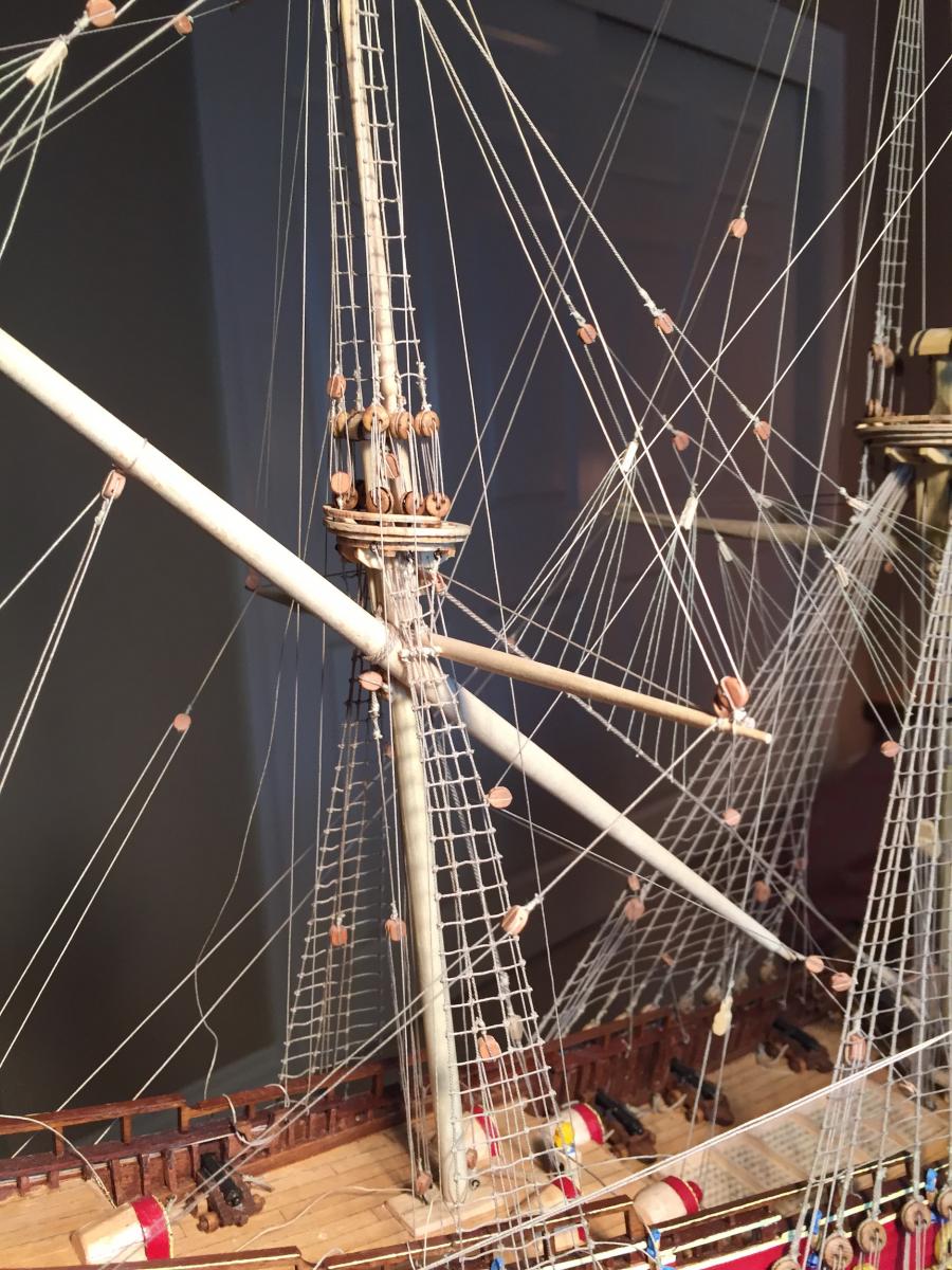
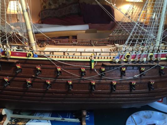
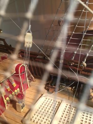
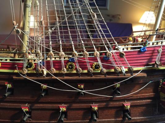
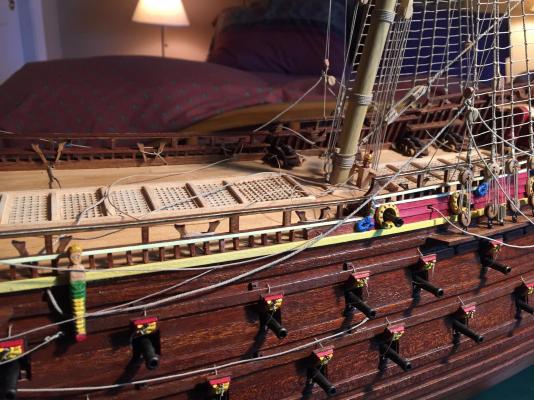
Technically the clewlines should be snugged up to the yard when the sail isn't bent to the yard, but that raises the tacks and sheets up high and makes them visually distracting, so I left the clewlines down and seized them to a railing. Here you see the clew block, sheet block, and the sheet. The sheet travels in a zig-zag path from a ring bolt on the hull, up to the sheet block, back to a block on the mizzen channel, then up to a kevel bitt, where it's tied off. I soaked the rope and brushed it with diluted white glue to get it to hang naturally. The tack starts from the clew block on one end, travels through the decorative sarcophagus-like sculpture (it has a sheave in it), then up, through the bulwarks and around a kevel bitt. More soaking and glue to get it to hang naturally. And the finished main yard rigging. None of the lines have been given their final tensioning or been trimmed - that'll happen when the topsail and topgallant yards are done.
- 249 replies
-
- 8
-
-
- billing boats
- vasa
- (and 1 more)