


Jond
-
Posts
749 -
Joined
-
Last visited
Content Type
Profiles
Forums
Gallery
Events
Posts posted by Jond
-
-
11 deck work nearly done and it’s time for a punch list
This posting includes the part of my builds where I may be getting to the end of the model part but have a similar effort to put together the story to tell in the summer months. First up though let’s see how far we have come… Since last time I have focused on the rigging and the stern. Also, more research on both fishing and on the yard.
For planning I share three images-
1
 here is the fore mast as shown on the Rice brother’s plan. After looking at several photos of different versions of a dragger, I chose to follow these plans. I am still guessing if the hoist line from the boom as indicated is for two dropped blocks with the halyards back at the mast, of if the single line aimed midship is the one halyard going down near the winch. There was a smaller winch I believe connected to the ice chopper forward of the foremast, so I may take the lines there. I am not sure the big winch running this line would make much sense.
-
2
 here is the mizzen mast. It is quite simple compared to others and I plan to keep it that way and add a sail for fun.
-
3
 In my continued research of the yard, I found this great image of the dragger Fabia, she was a wooden dragger 132 feet built by Brother Frank Rice next door in 1920. I share her to show quite a variation in rigging and only built 100 feet away. Thus, my decision to stick to the plans.
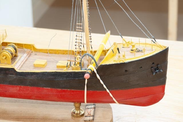
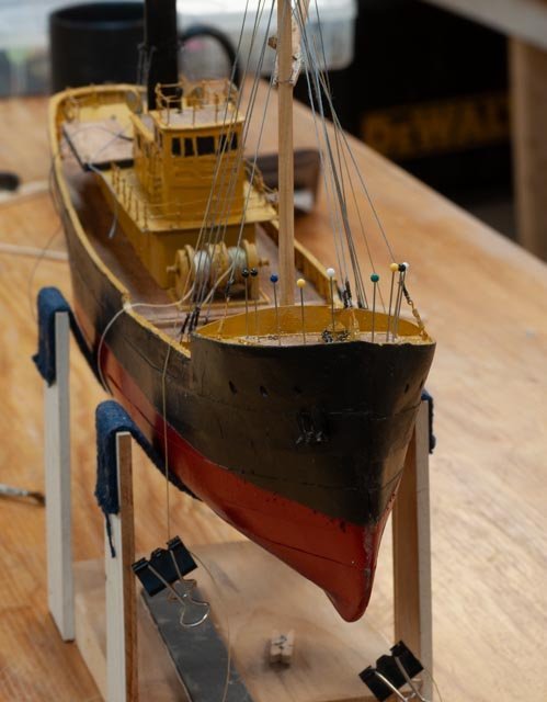
Work update. Here we are today looking at the rigging-
4
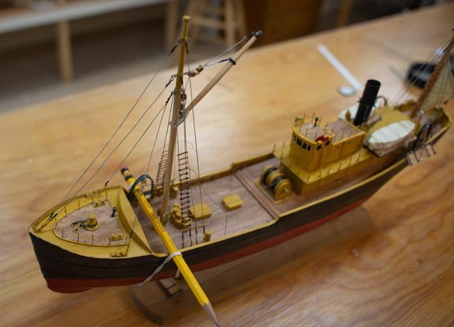 looking at the foremast I need to complete the ratlines, mast light and figure out the hoisting lines.
-
5
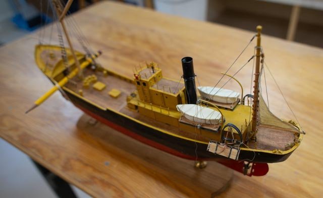 looking at the mizzen we see our sail is up . I used grey thread for galvanized cables; lighter weight with no turnbuckles for the stack.
-
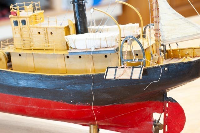
6
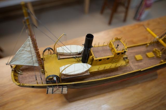 looking amidship we see the boats. Based on the photos they are on raised platforms pushed out to the bulwark line. This platform also provided a little more cover on the working deck. I found the idea of a single davit interesting and challenging for the users.
A few details....Thanks to Jerome I did not continue with rope for the main two net lines. I chose to use thin annealed steel to give the look that was closer to spun steel. The problem with my limited skills is how to make it tight enough to look like it is in tension.
-
7
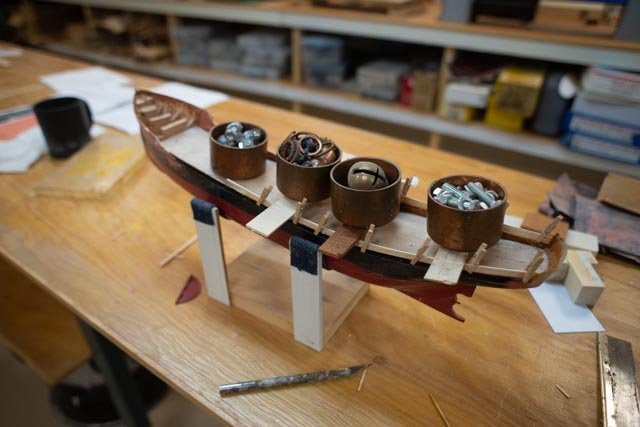
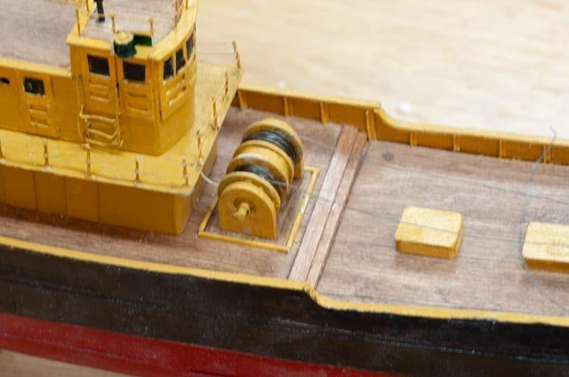 here we are on the reels. At a larger scale I might have tried braided picture hanging cable of some type of fishing leader.
-
8
 here we are with the active otter board on the starboard quarter.
-
9
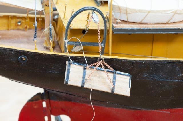 close up… It is still loose, and I need to figure what to do with copper chain etc. I ran out of good black tape and the shiny piece is awful.
-
10.
 This view is the inactive side and I am making the solution up. I spliced a heavy line to hold the otter board overboard on this inactive side.
-
11
 here up forward I am gluing down the active gallows frame.
-
12.
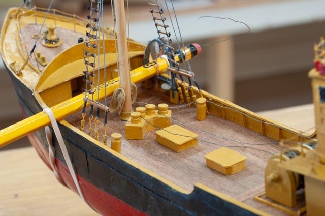 looking at the fore deck we see the cables are steel but a bit loose. I also need to figure out the ice machine foreword of the mast. I have decided not to include in this build......a guess at what the checkerboard type set up of compartments for sorting fish, missing quarter lines that would go from the end winches through multiple sheaves to the center of the net, stored net on deck[ after deck read], or any fish. I do, however, have a few figures and it is always fun to place them aboard too.
The punch list is really straightforward. I will be shifting more time into preparing the powerpoint story, so the model and story are done in the spring. Being me however, I will start another build by then too.
All for now.- SiriusVoyager, ccoyle, Jim Lad and 6 others
-
 9
9
-
1
-
Nils
thank you for your kind comment. I regularly watch your work and I must say it inspires me especially at this small scale.
cheers
-
thank you John and Jerome
Jerome you caught me just in time. I was already yesterday to connect the first line to the otter board chain at the aft gallows. Now I need to decide how best to replicate used but not rusty steel cable, I used the grey thread for galvanized shrouds and stays. If I use black, where is the shine. Perhaps it it new? I will think on it but not too hard...smile I appreciate the catch however and the "rope" will go away.
cheers
-
10 update on the deck work
This update does not reach any milestone; it just ticks a few more boxes. I wanted to start forward and work my way aft. I must say reading more about these trawlers simply amazes me about how tough the work was, and in some cases still must be. What I hope to show will cover the main control of the nets. I have looked at several photos but keep going back to the Rice Brothers plan when deciding what to build.
-
1
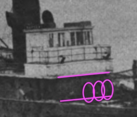 here is the blow up of our only photo of Harvard as a fishing vessel. The ovals are looking in the shadows to determine the size of the main cable reels.
-
2
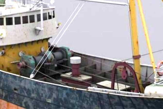 this image is another internet sourced photo of an older beam trawler. The reels seem a bit smaller, but the lines are clearly steel cable.
I don’t plan to include more images from the 1912 model by Erik Ronnberg but there is much information on how these things were set up and his interpretation of a deck lay out. He pointed out that he too had no deck drawings and few useful photos to use. His diagrams and explanation though were incredible as usual, and they make up my limited understanding.
-
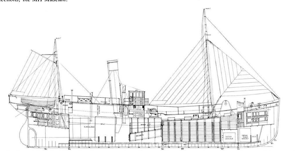
3
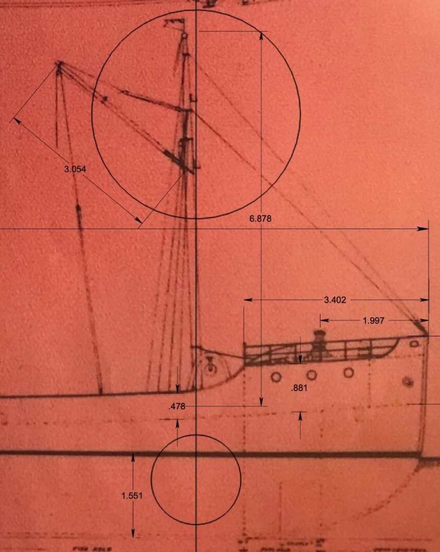
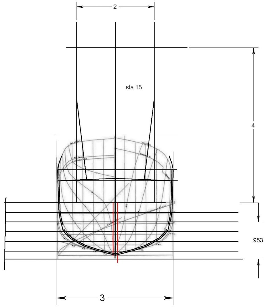
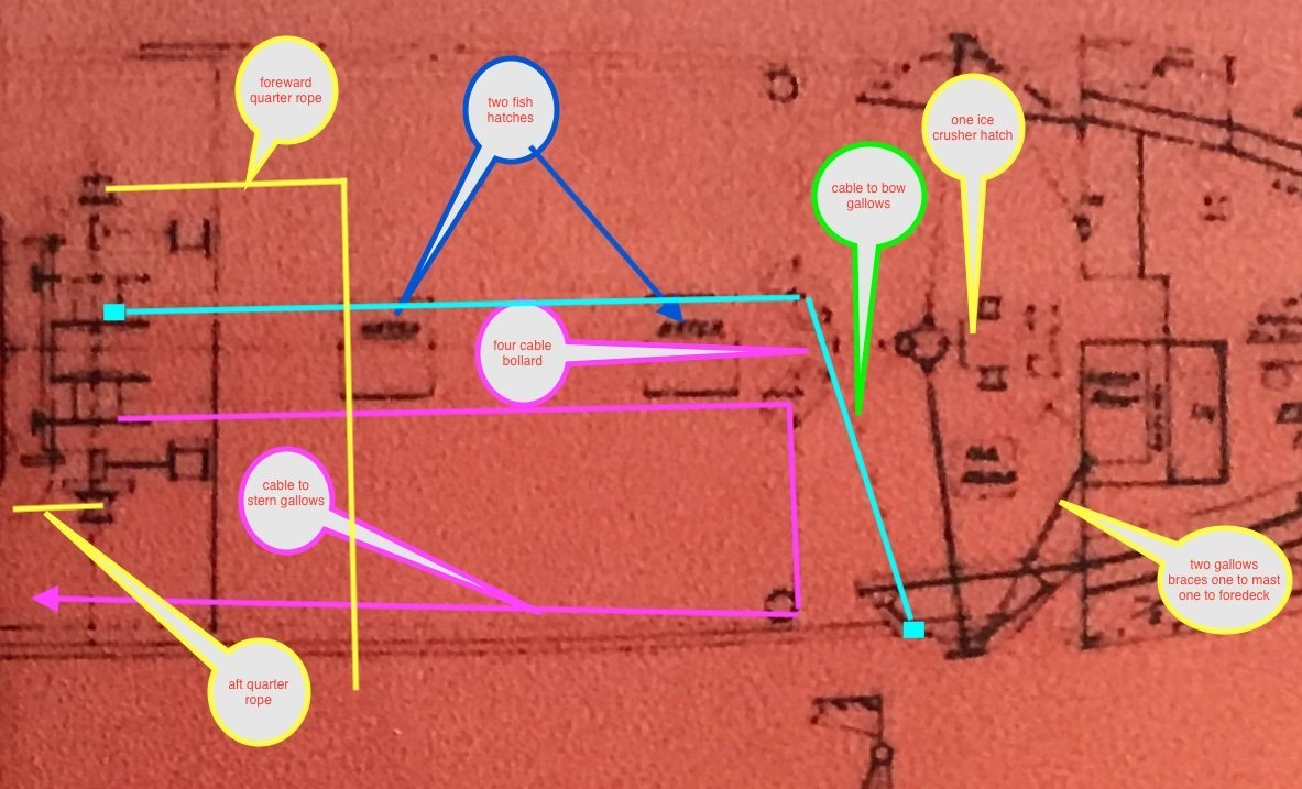 here is a blow up of the Rice Brothers drawing that I have annotated. I felt I could do that after reading all of Erik’s articles, so I gained a beginner’s knowledge.
Differences from his conclusion include:
• The side bollards to take the main cable aft to the aft gallows are forward and parallel to the main four bollards. Set up is the same for the 4 main bollards.
• There were two fish hatches not one.
• The gallows braces go to the mast and fore deck as there is no center cabin enclosing the foremast.
• The ice crusher/ hatch is forward of the mast.
Similarity includes…. I plan to assume rope for the main lines. If I learn that I am wrong I will hopefully be able to paint the exposed line dark to simulate ugly used steel cable…..smile.back to work
-
4
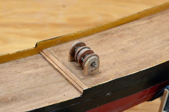 to make the reels I fell back to my non machinist approach that started making winches on the Boothbay Harbor One Design RC racing sloops I built years ago at 1:24 scale. Copper and brass washers of multiple sizes. The small end winches for the quarter ropes are two open brass open rivets. The shaft is combination of nested brass tubes going from the smallest holding the rivets to the largest holding the washers. There was flux and stuff all over it after soldering so I dropped it in a pickling bath thinking it would clean up. Oops that was not the right solution….see the salting. Anyway, after several attempts they cleaned up. I used Costello wood for the end frames.
-
5
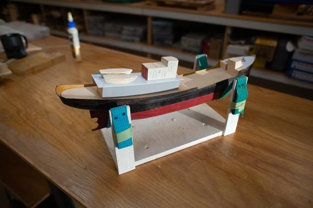
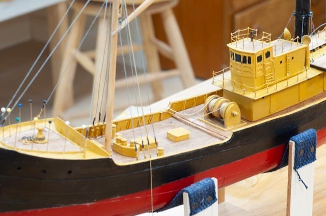 here is an overview of the large reels with rope coiled. The two hatches are in; just styrene on a block. The bollards are turned dowels set into a small block of poplar.
-
6.
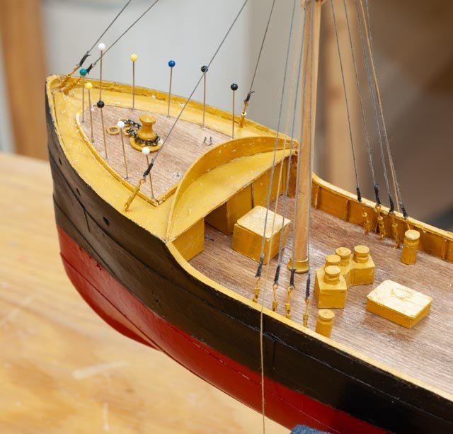 looking forward my rail method of cut off pins and tied painted line is clear to see. I am not ready to electro or is it resistance solder tiny pieces, so hopefully this method continues to work for me. The block for the ice crusher is a place holder now. The gallows are under way and are the main feature to come next. I was glad to read that the name breakwater is the right name for the curved plate.
-
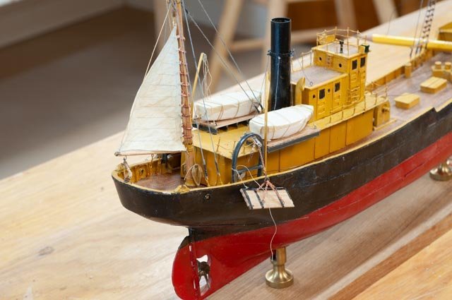
7.
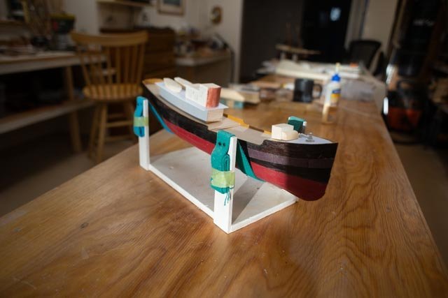
 just an overall shot. The cabins are in place, the rigging has started and the after deck work is next.
All for now
- Mirabell61, FriedClams, Valeriy V and 6 others
-
8
-
 1
1
-
1
-
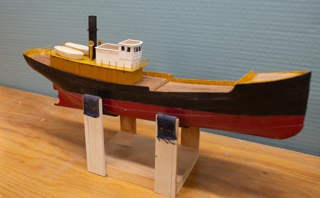
9 fore deck and cabin work
As we complete 2023, I wanted to have the basic “canvas” [ hull, decks, and cabins] done so next year I can focus on learning how they fished and what a trawler was all about. I also wanted to fit my work into the story I am forming to tell next summer to include the work of the Rice Brothers and how their inspiration of introducing steel hulls made such a change to this market. Meeting with Robert Rice, heir to the famous shipyard, has opened an incredible source. One example is how he helped me decide on one of the options I shared in making alternate mockups for the main cabin/ pilot house. As I previously posted, I was wondering about the difference in the shipyard drawing with the undated photo of Harvard within which there is a raised platform around the deck house. Robert told me that in the earlier days, unlike today, changes to the work in mid-stream were less often and less significant. Looking at the Harvard photo he concurred that the platform was likely a later change, not original. I decided not to add the raised platform around the pilot house. That decision also means I am most likely keeping the build to match the other draggers of the same design built earlier, 1918-1921 in the same yard.
I share below my process to decide then build the foredeck and cabins.
-
1
 here is a great drawing from the Erik Ronnberg article explaining the cross section of the typical dragger of this size and era. I note the fore cabin for the crew in this version goes fully below the main deck level. In the Rice Brothers drawing the crew quarters are all above the main deck. The plan here raises the foredeck with a rounded deck line [ seen is previous posted photos] . it is not the same. Also confirmed with Robert Rice the Boothbay built draggers did not have aft below deck captain cabins.
-
2
 here is the Rice Bros drawing. We see the portholes and the full height of the deck. There is a rail and a breakwater [ not sure of the breakwater is the right name of that feature, same as on lightship], and the anchor winch.
-
3
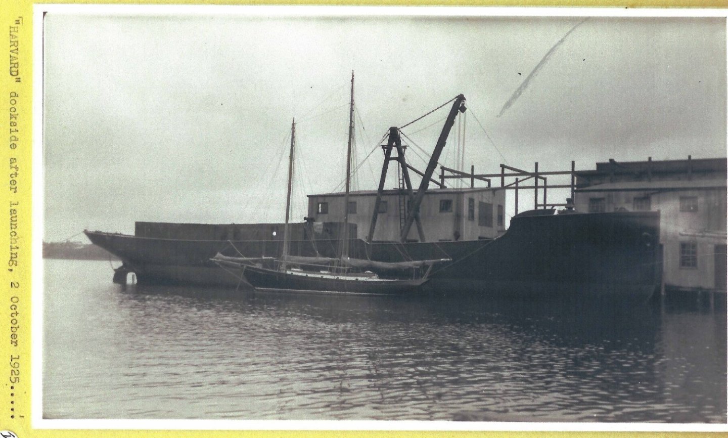 here is the Harvard alongside the dock after launch. The high square foredeck is clear.
-
4
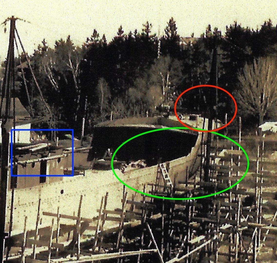 here it is hard to see, but I believe visible enough to clarify three points.
- Red oval: the fore deck has rails and wood surface in the center and curved breakwater just like the Ronnberg model that I shared in an earlier post.
- Green oval: the profile of the bulwarks is what I am trying to follow. The raised deck starts before the main cabin running aft as the bulwark suggests.
- Blue rectangle shows the configuration of the lower main cabin in steel with brackets for the top deck.
-
5.
 here is the Rice brother’s drawing cropped for the cabin profile and deck rails. I used this for the build.
To work
I decided to make the upper deck, stack and rail stanchions using brass.
-
6.
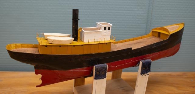
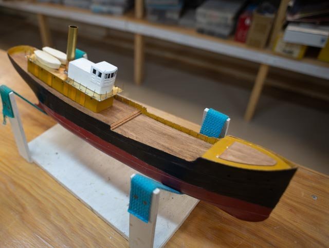 here is a dry fit. Also noted the wood decking portion of the foredeck.
-
7
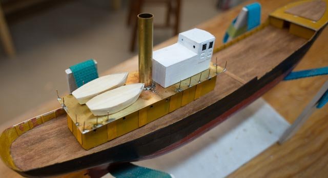 in this closer view the styrene angles are used for the bulkhead stanchions. I use the angle not because I know that it’s right, it just looks more like steel and not wood.
- 8. ,9. Here are two New Year’s progress photos.
-
Looking forward I need to learn more about how the draggers worked.
Happy New year
-
1
-
8 progress on the hull
Just a few bits of progress heading to the end of the year. I need to complete the stern and bow and then with a sub deck in place get the bulwarks done.
-
1
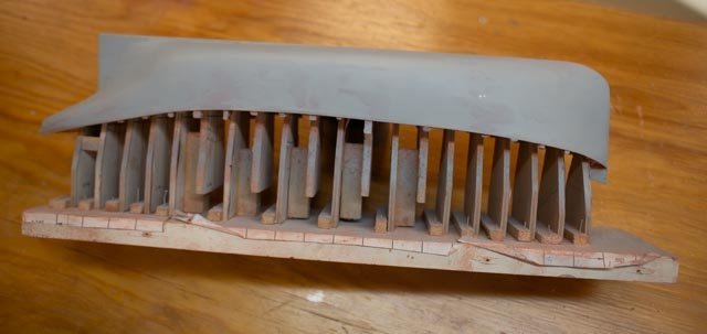
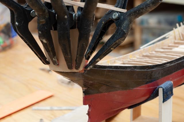 here I am building up the fantail using 1/64-inch plywood.
-
2
 as we see clamping is tricky.
-
3
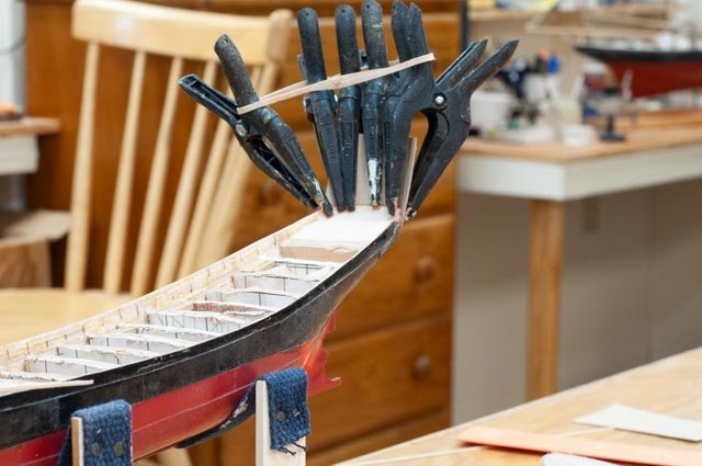
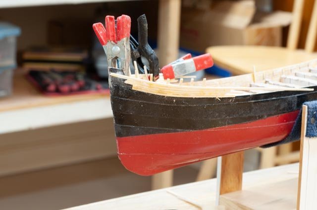 here I am building up the bow. I have chosen to follow the photos of the real Harvard at launch.
-
4
 here is the Erik Ronnberg bow. Note the rounded affect. I like the wood deck insert but do not follow this curved profile.
-
5
 here we see Harvard being launched and the fore deck is clearly as high as a man. A second meaning is there is clearly room for the crew area under the foredeck. The design drawing I have varies a bit but includes three portholes for three births in this area.
As I mentioned before, I was not happy with my first rudder assembly as it ended up off center. This new set up used the aluminum foil to raise the little tube gudgeons and rudder hopefully to meet the centerline of the post.
-
6
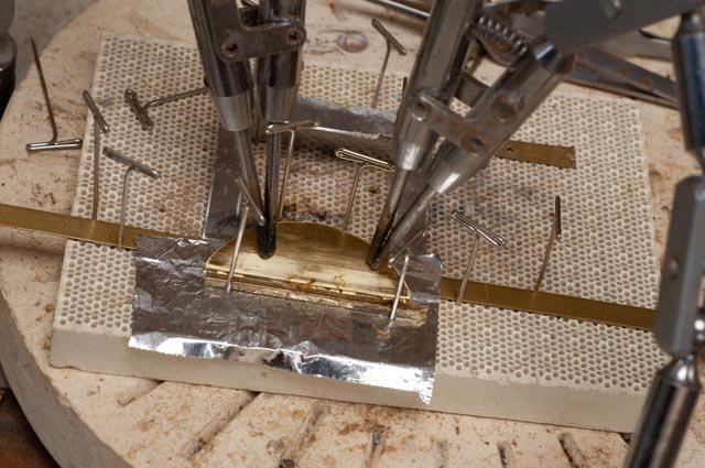 here is the set up. It came out better, but still not on center. I may go one more time to try to get this right.
Now time for the sub deck and bulwarks. As I shared before I goofed by making the bulkheads too high in such a small model. I roughed them down and to recover and decided to cheat. I added a 1/64 plywood sub deck to mitigate the issue.
-
7
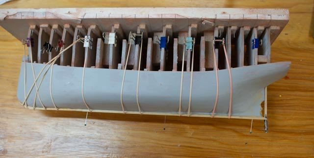
 here we are gluing down the plywood sub deck.
-
8
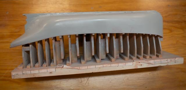
 in this view I am gluing on the reraised bulwarks to meet the profile.
And here are two photos for the xmas progress.
-
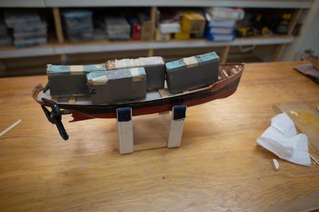
9,
-
10
 the little wood blocks are still mock ups of configurations from different sources, since I have yet to find good photos of the completed vessel. I am still looking. I also have confirmed in the photos, but not the drawing, that there was a breakwater across the top of the fore deck to hold back water from coming on board. The question is, was that installed when built or added later. More on that subject next time
Happy Holidays
- ccoyle, Roger Pellett, Valeriy V and 3 others
-
6
-
1
-
07 what should the deck house look like?
The last week has included more searching while I peck away at completing the hull. I received a few pieces from my friends at Bluejacket, so we can add anchors and the like. I am also fretting over my deck support dilemma. I am trying out a short cut and will see if it works......
-
1
 First up…. here is photo of the construction paper on the hull before paint that I forgot I had taken before painting. It should have been in the last posting.
-
2
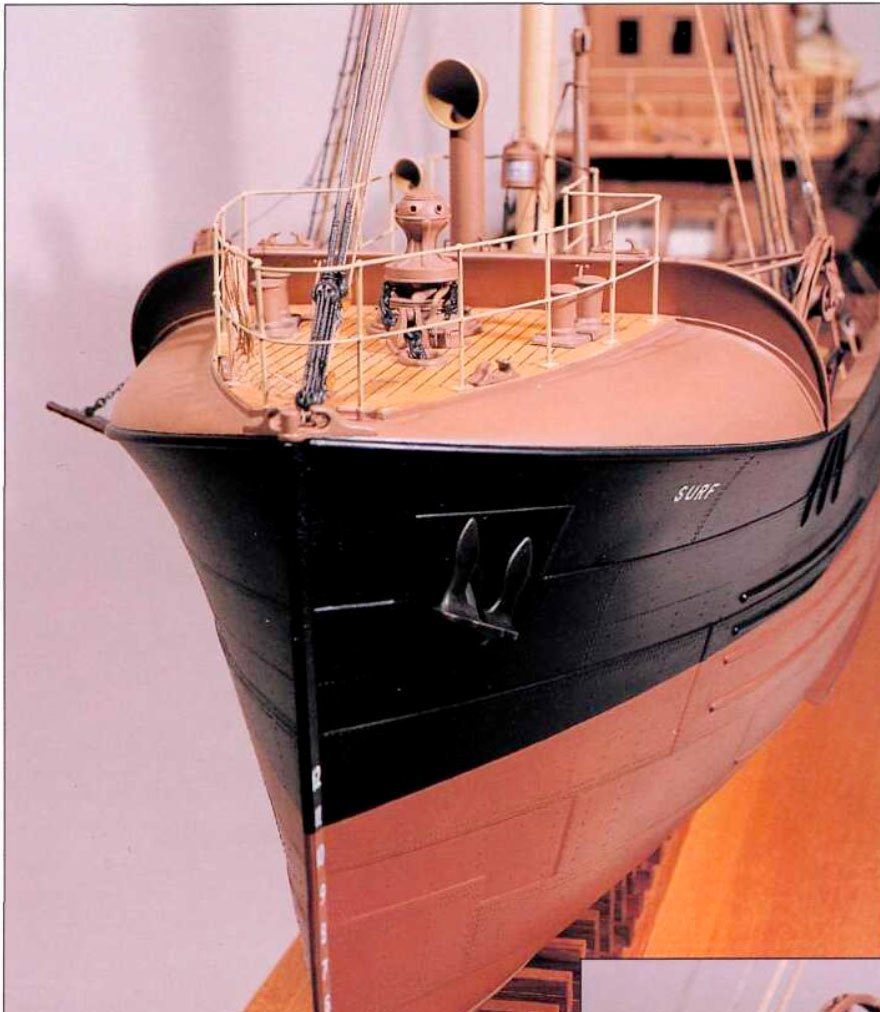
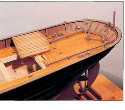
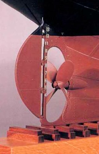 Second... we look at the master’s Erik Ronnberg rudder and propeller.
-
3.
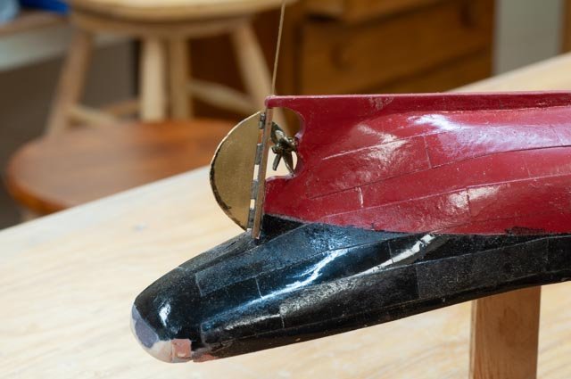 Here is my first attempt. It came out with some defects that I will have to rebuild. I need to figure out a really thin shim that will not attract solder to hold the rudder at the center of the thicker post. I had set a aluminum sheet under the brass rudder , but unfortunately, I ended up with the rudder off center…opps I share the good side …smile
Now to the study of deck house
-
4
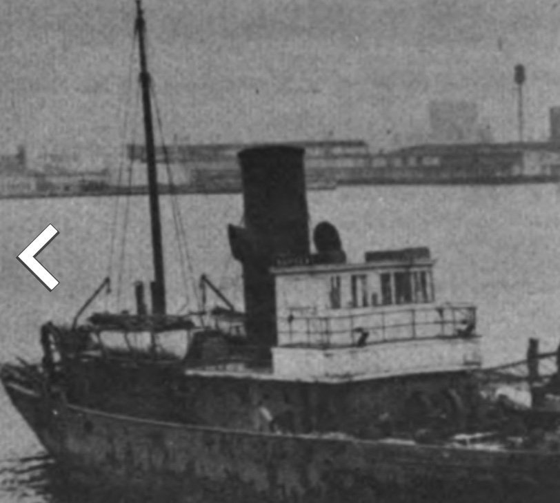 here we see a blow up of the only photo I have been able to find of Harvard in at some point in her 20 year fishing career. Note the platform surrounding the pilot house. It looks like the top level roof goes back toward the stack [. This is the critical point discussed below]
-
5.
 this view is blow up of the Erik Ronnberg model of similar design. The pilot house is very small, no captain cabin behind. The lower-level cabin is much in head room etc., and the stack is forward and through the deck house. The view is invaluable for detail but not our configuration.
-
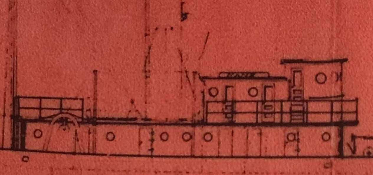
6
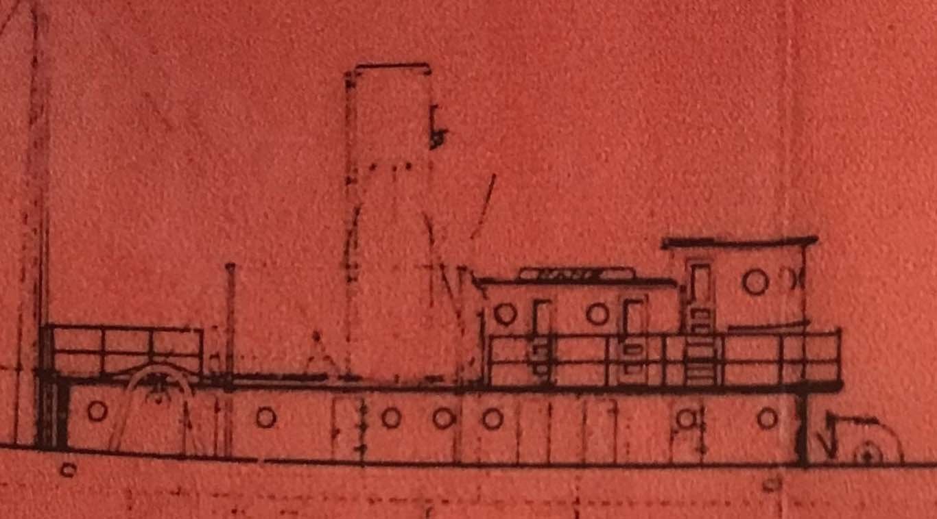 this blow up is from the 1920 +/_ Rice Bros drawing for the four trawlers. It should be noted that they were launched 1919-21. There was a recession in 1920 and many fishing companies were in trouble and cancelled orders. It was not until 1925 that Harvard was contracted again and was completed. Thus, it would have been possible for a different configuration. The two capt and mate cabins may have been squeezed it. It is hard to determine from the photo. The whole upper level was raised and I feel it is clear it ran aft behind the pilot house door, but for one or two cabins would be a guess on my part.
-
7
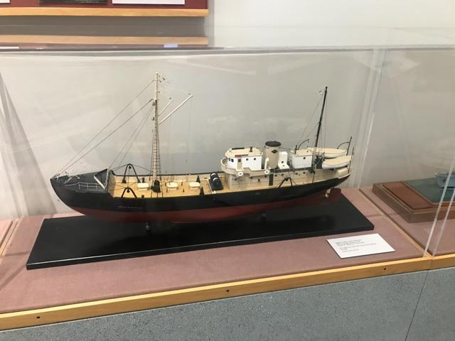 finally here is a photo of a trawler at Maine maritime Museum. I find it interesting of the similarity. It clearly includes a captain’s cabin behind the pilot house. It also has a small second cabin behind. We are definitely in the right family of vessels.
Now what to do??
-
8
 here is sketch showing the three options. I have determined to follow the plan for the long complete Lower deck house as drawn. There may be a variation in doors, but something needs to be decided.
-
9
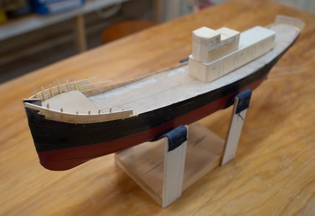 here is a mockup of what the configuration would be if I build to the plan.
-
10
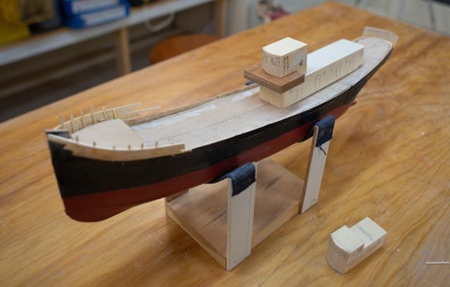 here is a mockup of what the configuration would be if I build to the photo.
I will need to decide which way to go. I will have access to more of Robert Rice documents soon I hope, and that, along with talks with Robert will be used for my decision. In the meantime, I need to continue to peck away at the hull, solve the deck so i can get the bulwarks figured out. The fantail has been roughed in with 1/64 plywood. I need to see if I can make that work too.
plus it is the holidays
cheers
- FriedClams, Valeriy V, GrandpaPhil and 2 others
-
5
-
1
-
Thank you Gary and Roger
Gary. watching your builds inspires us amateurs to give fishing vessels a try. the big winch that runs everything is well over my pay grade and will take some more study.
Roger I have a friend here who is a machinist and he said to me he uses both, so I am sure I will be off to Amazon again for a sponge. My brass rudder is off center, as the aliuminum shim was too thick, so I will show the good side in the next post but know I need to re build it....smile
cheers
-
6 let’s figure out the top rails and hull plating.
Sometimes I think I am so smart… then I suffer. In this build I made the top of all the bulkheads to be at the deck line. I used this method in larger models where one has reasonable access to sand, remeasure and adjust. I was thinking this is a shortcut, as the deck can then just sit there. Well, it was not that smart. Unlike a 4-foot RC sailor with 10-inch-wide deck, or even a 27-inch schooner with 5 inch beam, I have less than 3 inches across the deck. There is no convenient way to get in there with control to sand down multiple bulkheads for that nice surface needed to directly place the decking. If I had made them all just 1/8” lower, I could have made up deep deck beams and glued them to one of each bulkhead. In one day, all would have been done. Now who knows…
In the meantime, we need to figure out where we raise the bulwarks to fit the profile and set top rails. We have several sources to use:
• The Ronnberg profile drawing is our starting point. The rounded “domed” fore deck shown in his work was not evident in the photos of the Maine Trawlers
• The Rice Brothers photos are the goal. A few adjustments may be good enough.
• Internet photos of Harvard then Bellefonte then Albatross III. Unfortunately, the vessel was extended 20+ feet all in the forward area so interpretation is required.These all together should however be enough to cry uncle.
-
1
 here is the detail line drawing from the Ronnberg article that sets the designed bulwark dimensions for vessel. I have annotated a few elements to give heights for the bulwarks. The deck line is also shown on the profile drawing to check as well.
-
2
 here is a detail photo of the Ronnberg model trawler fantail. Mine will never look this good but it is something to aspire too. I thought I would first try to do this in 1/64 birch plywood and if no good, do it in styrene. Let’s see where it goes.
Just last week I began a series of interviews with Robert Rice. At 85, he is the last remaining Rice brother heir that worked in the plant around 1950. He chose not to stay there, and he spent 28 years in the army. When he retired in 1976 and began building houses. After a few years, he realized no one had memorialized the family history. He decided to do that and spent the next 40 years accomplishing an amazing library of photos, models and records. He joined with Jim Stevens, an East Boothbay Shipbuilder in his own right, who started the local Boothbay Region Historical Society where much of their work resides. In his home he has a 5-foot shelf of photo and memorabilia albums showing every vessel. He has great models too. He looked at the model I recently made of the Lightship Overfalls and instantly showed me an error…oops. I will post that over on that log next week as it is fun, and I will include a photo of his model of Columbia and the story of the major design changes that Rice Brothers had done to the two ships built around 1950.Back to the trawlers. Quite a story.
Jacob Stevens, who a few years later opened his own yard, was working as the designer for Rice brothers when they won these Trawler contracts and the first lightship Poe. Unfortunately, a fire in 1951 destroyed all the stored drawings. A few survived including a profile and deck plan for these trawlers. I include here a photo of the photo in Robert’s album of the Beam trawler blueprint profile. There were 6 variations of them built but here is the plan…..wow what a find.
-
3
 the plan profile as developed by Jacob Stevens who worked at Rice bothers for years before starting Goudy and Stevens yard in 1920-24
Now let’s do some comparisons. I cropped and blew up each portion to compare and plan.
-
4.
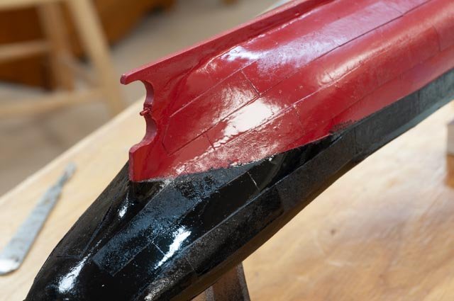
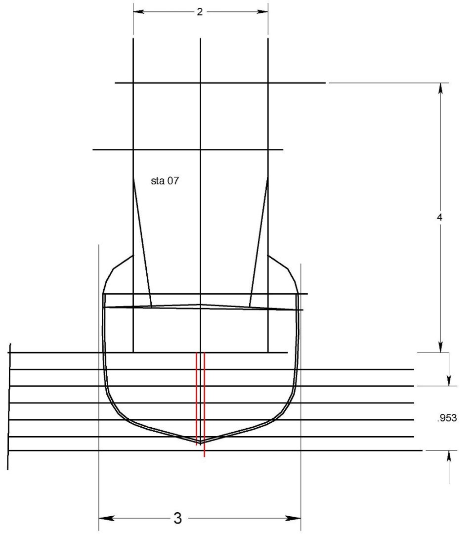
 here we see the bow area. I show both the Quincy Ma [ via Erik Ronnberg] cropped profile with the Robert Rice photo. I will do my best to replicate the Rice Bros drawing but note the lack of high foredeck visible in the photos.
-
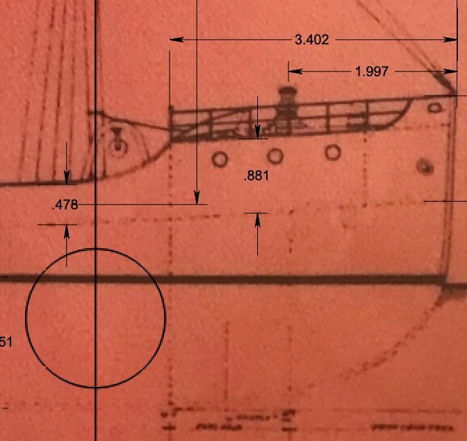
5
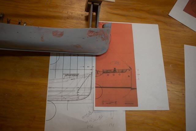
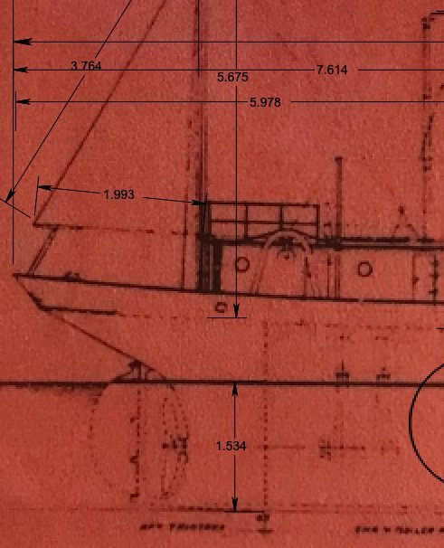 here we see the stern on a red color version of the blueprint Robert had. This red version is clearer, and I am using it for dimensions. I scaled it in Turbo Cad for that purpose. It seems the Rice Bros profile had less rise than what I have built. I need to acknowledge that, but we have followed the Quincy, Ma. lines and have what we have.
-
6.
 here I share the whole profile. I am thrilled to now have drawings of the on-deck features to follow and that is key to getting where we want to be.
Any work going on?
If I have learned anything in the 10 years of this work is get the sequence right. I am trying to finish 4 things at the same time and some impact the others. I think I figured our my “path”.
-
7
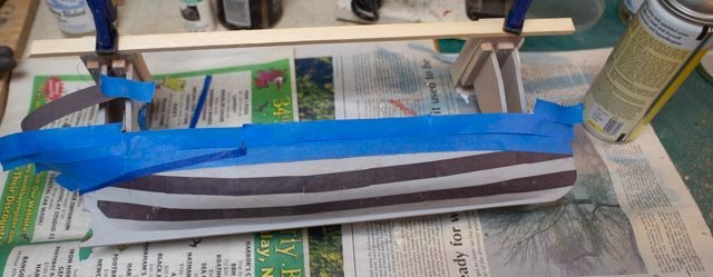
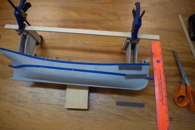 here we see the blue tape indicating the top of top outer plate. I cannot complete the added bulwarks until I remove the stands, as they are used to maintain the waterline dimension. The lower tape is the water line. I need to get the out plates on, then the waterline painted then remove the stands and complete fixing bulkheads for deck and bulwarks for rails.
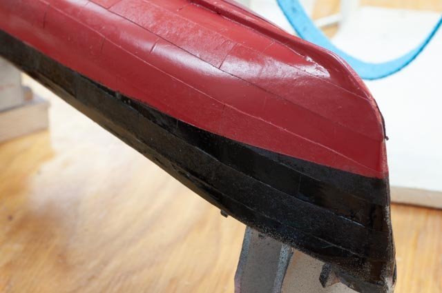
Following the tip from Roger, I bought spray shellac and applied it to construction paper before cutting strips on a paper cutter. I then cut both 8 foot and 12 foot in scale pieces and laid out the out “strakes”.[ not sure what one calls a line of plates]. I then cut vertical lines in the remaining hull to represent the same type plate spacing. I used simple diluted white glue to adhere the paper and then rattle can red and black. I suppose I could have applied a double layer of paper but decided at this scale not to do that. I would add plating to both inner and outer if trying 1:48 or bigger scale. Here in three pictures, we see the result. The Satin label on the cans failed me as there is a definite shine. We all know there will be another paint job after all the remaining work, so I will dull it down a bit.
-
8.
 stern view
-
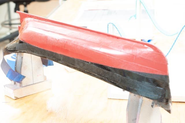
9
 bow view
-
10.
 over exposed but whole view to see the plating.
Next up will be to complete the bow stern and raise the bulkheads and get ready for the deck.All for now
- FlyingFish, KeithAug, FriedClams and 6 others
-
9
-
1
-
Andy. thanks and interesting. I have read several references as well that the big four,five six master schooners often needed tugs too. I recently learned of a whole new niche of schooner barges that combined old schooner and even ship hulls with the big tugs
tugs looks like they may deserve more headlines than they get . I ll save that rabbit hole for later.
back to fishing
-
thank you Roger Andy and John for dropping in
Roger.
following your work I have been watching a few more soldering tip videos. I have ordered a brass tip cleaner and when it comes will work on tinning and maybe some brass work. I currently work woth a blow torch. very amateur .
Andy
I agree with keeping a bit of a gas motor before heading out too far.....
the anxiety reminds me of Robert Perry who had chartered a steam powered bark named Windward for his 1898 voyage. under power it only did 3 knots so he waved good by in New York city and took the train to Sydney, Nova Scotia to meet up with her. Early stream did not enhance travel speed in sail other than with no wind or direction etc. I agree with your thought that perhaps fishermen were nervous to go cold turkey all engine. It is interesting if one simply googles trawlers and especially adding in the search "models" one quickly is in the world for sail power trawlers. hardy soles to say the least.
John.
would love to hear about trawling down under. did the market follow the British model and go to steam before 1900?
cheers
-
Roger
like many other of your followers I am reading your posts more than once. I am learning much as you tackle the many challenges of working to replicate on deck details. Your brass work is wonderful and inspiring. I may try a little.
the hatch covers introduced your use of the 'NRG thin rig guide , and has encouraged me to buy one. I find ripping less than say 3/32 against the normal guide from a sheet gets me some variation. Thanks for sharing that tip
jon
- mtaylor, Roger Pellett, Canute and 3 others
-
6
-
Thank you Andy Roger and Jerome.
Andy. there are images in the Erik Ronnberg articles that show sails fore and aft on the two masts. Those plans were for the Boston market 1905-1912. I will add those images later when I hopefully get to rigging. presumably they were for either stability or emergencies.
Roger. I remember being entertained and learning of the competition and jokes amongst Finn. vs Swede in that part of america. My relations were Swedes of Wisconsin and I had a college friend, a Finn from Minnesota. I am also holding my breath as I study your decision to go all brass above the deck in your build. wow.
Jerome. always a pleasure and I will be asking more help again once I get to go above the deck work. I may try some brass we'll see. I also have my supply of styrene.
cheers
-
Roger
Thank you for dropping in. Also, thanks again as it was your tip that got me to Erik Romberg’s articles. thanks for this hint as it answered my exact question.....I had read much of your blog previously ands went back last night to reread. Somehow [ though it was over a year ago] I had missed the entries you referred to here about using spray shellac on paper before installing. I did remember the part of having a bowl of warm water handy…funny how common sense helps. Wow great tip again and exactly what I am trying to figure out.
Running through your blog again and seeing all the great lake mariner’s input I have one too. My father-in-law grew up in Superior, Wisconsin. His dad was an ore boat captain named Anderson. My father-in-law learned to dislike the water and escaped first to college in southern Wisconsin and then moved to west Virginia in the 30’s. Then one day in 1940 he joined the navy and became the engineering officer on a tin can destroyer all over the Pacific. His stories were not filled with fond memories of Oceans.
Anyway, thanks for your help and inspiration through your own work.
-
5 Wood becomes steel.
Well, I sanded the two-part material shown in the last post and was unhappy with the result. I switched immediately to the one-part glazing putty by Bondo, that I have used over recent years to my satisfaction. Moving along, we see a sequence that seemed unending. Let’s follow the photos as we magically turn wood into steel.
-
1 and 2.
-
 These represent coat 2, putty over wood filler.
-
3
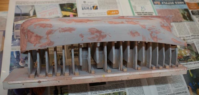
 here we have sanded and used the auto body filler primer. It is here we see many of the defects that are hard to see before painting and we sand again.
-
4
 after sanding the primer we go to coat 3.
-
5
 sand and prime again
-
6
 here we are at coat 4
-
7
 after coat 4 the primer starts to look good…but alas not good enough.
-
8
 time to add the skeg so we can blend it into the finishing. I also made the rough cut out for the propeller. I probably will need more but will wait till I get it in hand.
-
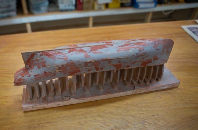
9
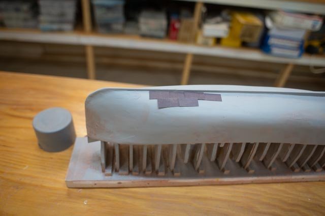
 coat 5 the defects that are covered are not as big as the stain from the putty. We are getting closer.
-
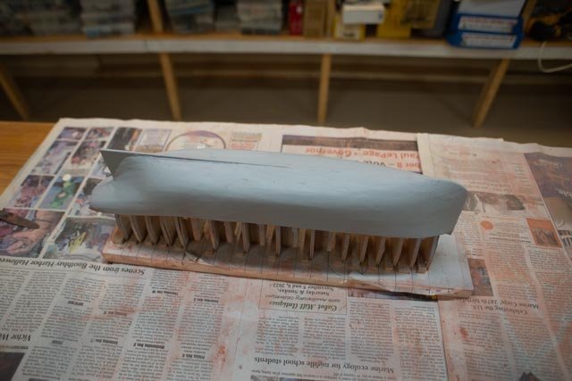
10.
 really close this time, still need to go again
-
11
 coat 6 this time I hope we are there.
-
12
 finally we are done. Here I am choosing what weight paper to use to replicate the plating.
It is time to think about how to make the plating. We have a few images of the later vessel. I also have learned from the last remaining local Rice brother’s family member that worked there around 1950 that there was welding included in these early draggers. The lightship built in 1921 was fully riveted but these dragger hulls had welded plates. He shared that all vessels by the 1930’s in the Rice Brother shop were welded. The coast guard had a few requirements and the 1938 Lightship Cornfield was welded below water and rivets above water. I know that as I finally visited it last week.-
13
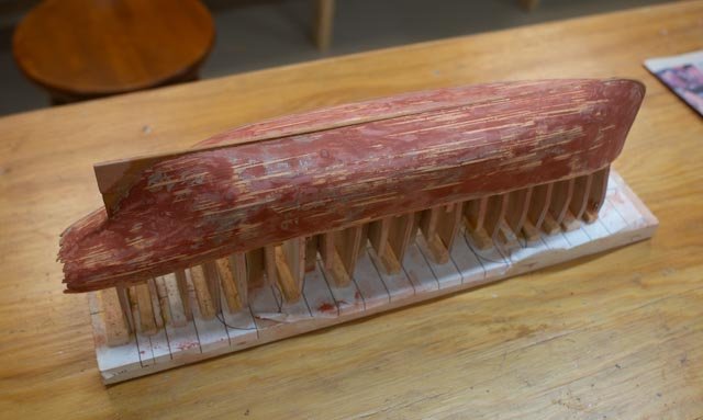
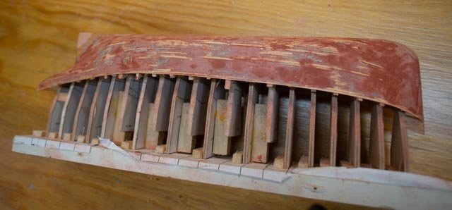
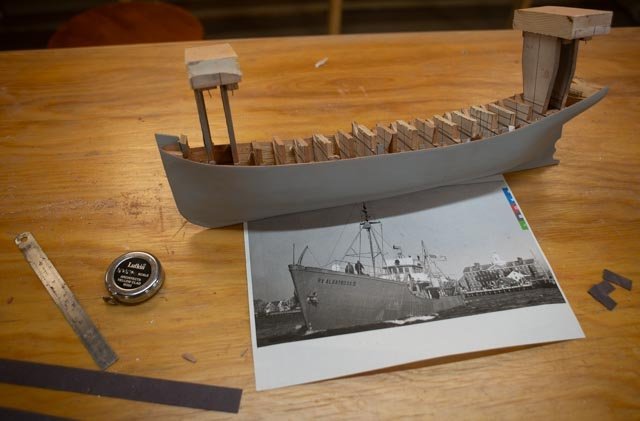 We end here having removed all but two sets of bulkheads . The two sets remain as stands and will let me set the water line, but the openness will allow me to figure out the bullworks, the bow and stern areas that need to be completed next. The photo and construction paper are my preparation to figure out how to add the steel plating. the photo clearly shows the alternating in and out of the "strakes". They also show i need to finish the bulworks first so they are positioned correctly.
all for now.
- Retired guy, Valeriy V, KeithAug and 7 others
-
10
-
1 and 2.
-
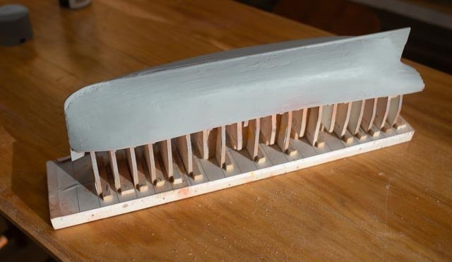
04. Get those planks on
Steel out of wood. Hopefully it's not something new. My plan is the age-old trial-and-error approach. I will plank with 1/32 basswood and add liberal coats of glazing putty then sand and putty and then sand. Then add the outer strake to represent the look of a riveted hull. I will not try to replicate rivets. Considering there is no attempt to see the planking, the planking installation is expedited.
I broke up the sides into 4 bands. The full side was 24/8” [ 3”] most of the way. Each end tapered to 20/8”. I used a razor blade to chop down and taper both ends of the planks for most of the runs. The planks were milled to be 5/64…..shall we say more than 1/16 but not quite 3/32. I have the right tools and most of the planks were right on but…I used the ones that weren’t too.
First up was to solve the underpinning. I added soft pine blocking bow and stern and carved it to shape using a Dremel and careful sanding. The stern block is not all the way up to the top rail, as believe from looking at Erik Ronnberg, the master’s model, the aft bullwork up to the taft rail was ultra-thin. I think that is better built after we have access, and avoid having to carve back out the blocking. Similarly, the height of the fore deck and thin bulkhead suggest completing that work after removal from the building board. Again, we’ll see when we get there and hopefully not regret the approach.
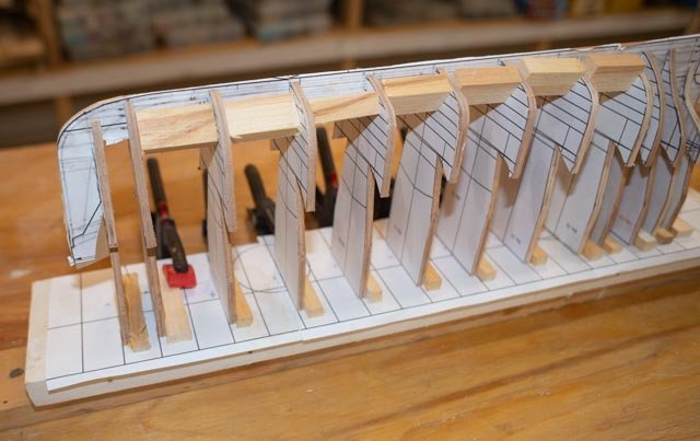
To work.-
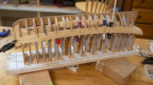
1
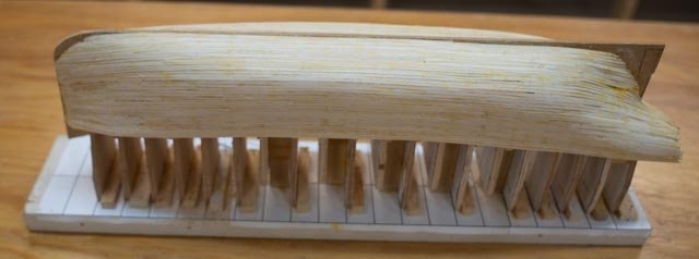
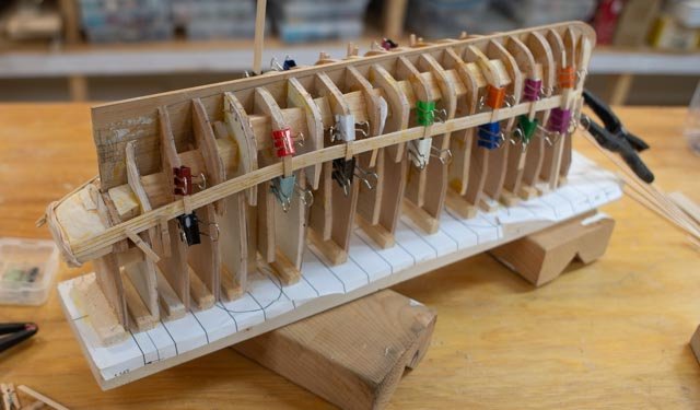 here I have added the five intermediate bulkheads. They are the ones that do not reach the building board. It was a bit of a challenge but we did it and the first four planks are in. The placement is one below and three above the upper band marks. [ sorry only pencil] I did not spile these 4 planks, but all the remaining ones were tapered.
-
2
 some more progress. Clamping is always an adventure.
-
3
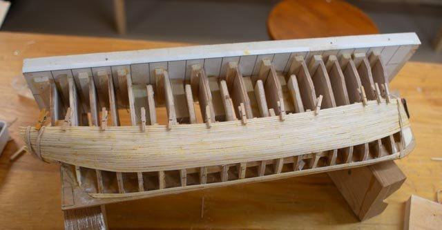 here the top band is completed.
-
4
 here I have the garboard and extended planks and bow coming along.
-
5
 here we are working the tricky double bending of the stern. Thank goodness this is not to be exposed wood.
-
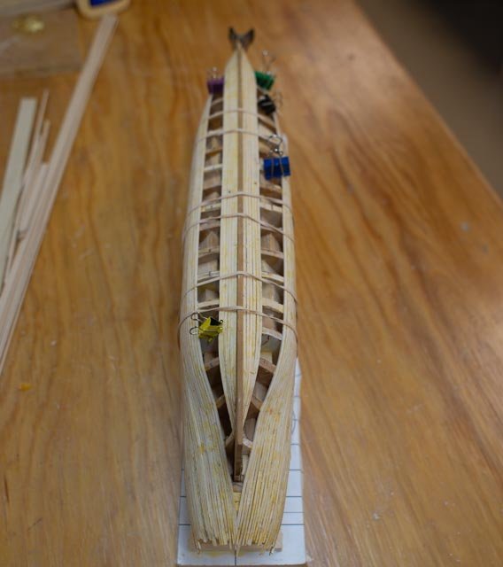
6
 ta da. All in
-
7
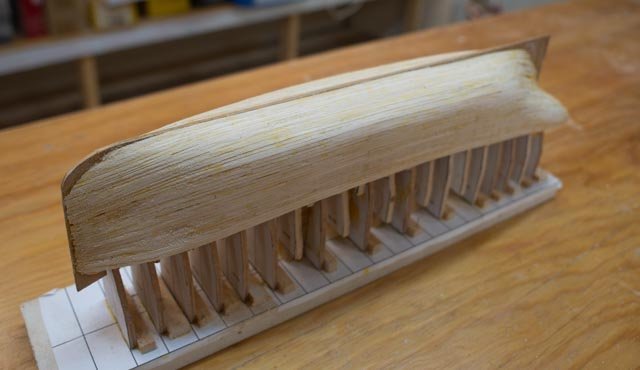 I see here that the keel needs a hair added on...oh well
-
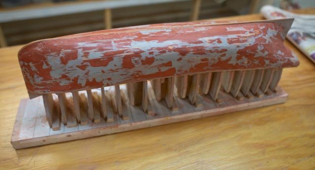
8.
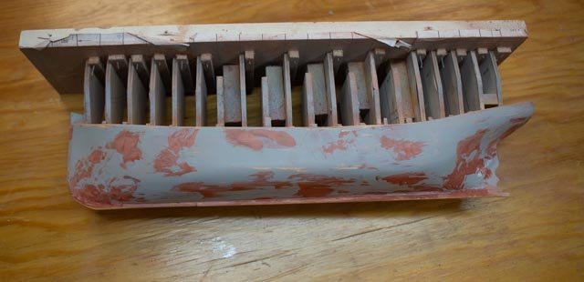
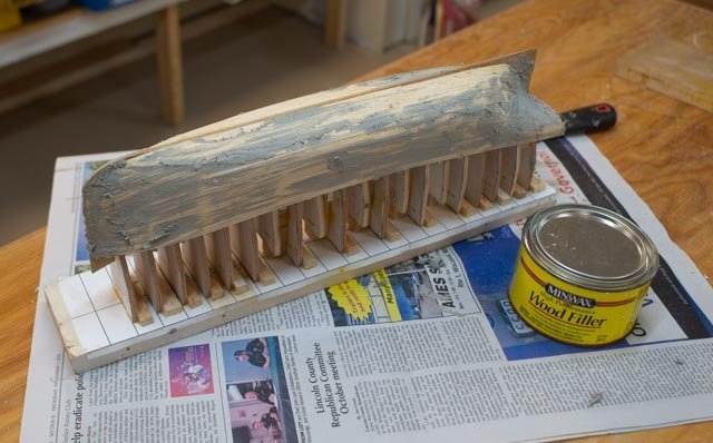 and quickly let’s get a coat of filler to cover it up. I decided to use a first application of two-part filler since there were quite a few defects, especially on the stern areas and such thin planking. Once we have two, if not three, applications in place, I will move to one part glazing putty for smoother finish.
Happy Thanksgiving.
-
1
-
03 where are the plans?
About a month ago I posted a request for help on MSW research blog looking for 1910 ish beam trawler plans. It worked! Thanks to a brief exchange, I was tipped to go find Erik Ronnberg articles from NRJ, perhaps from the 1980’s on the subject. It was easy to do using the NRJ index and CD’s.
The essence that came through reading these articles was that as the century turned, American shipyards still built schooners. They did not, as the Brits had already done, move into their own development of large-scale powered steel trawlers. Then in 1905 or so British designs came to New England to kick start our industry. Erik R’s amazing 5 articles, which include full images of an amazing build in 3/8” scale, is worth a detour for anyone who finds this subject interesting. He also discusses the beam and otter trawling and other technical or equipment developments along the way. The vessels were built in, Quincy Mass for Boston owners using British inspired design. Ours here in East Boothbay were also built for Boston owners.
There are 5 articles, and they include history, photos and yes, all kinds of plans. The size was almost identical, and the look also is the same. The article shows evolution between 1905 and 1912 and the difference is subtle. I chose the older as it is just a small bit is less curvy.
-
1.
 here is an image from the NRJ articles to compare with images of the launched hulls in the last post. Pretty close I think, so we are solved as to the source, and now will look to the photos for the details.
So, what to build and how. I want to celebrate this early stage of steel work. My recent build the lightship Overfalls 1950 represents the end of the Rice Brother’s era, as the yard was closed by 1956. There was a total of 6 draggers built between 1919 and 1926, plus the steam passenger Bainbridge. My selection, to sit beside the completed model of the lightship Overfalls, will be the Trawler Harvard in the same scale 1:96. I am new to faking steel and I don’t know much about fishing equipment, so the smaller scale helps me there too. The photos of the 1912 model by Ronnberg [ way over my head] will inspire me to try to make a go of rigging, plating the hull and fitting out the deck. At least I hope it won’t look like a schooner with short masts.To work…
I set up the plans from the article and embedded them in my apple system Turbo Cad. It is more than adequate for the simple 2D re-scaling and station drawing that I do. I would not recommend it for a serious CAD process.
-
2.
 Here is a typical station with the embedded line drawing still turned on.
-
3.
 Here I turn the embedded photo layer off before printing my patterns.
-
4
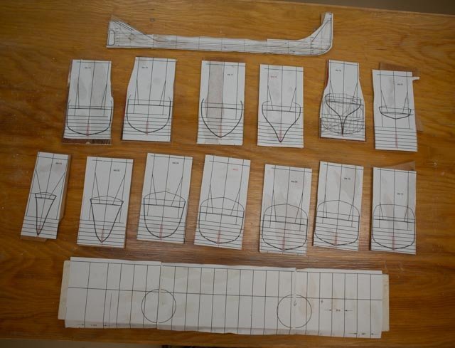 here the patterns are glued up ready for cutting. the inner line is for sanding down to account for the intend 1/32" planking. On a separate drawing I scale the “Keel-stem assembly and stretch lines to make up a building board pattern for the stations.
The first phase is just to get the stations cut out and attached to the build board with blocking. That step is all I have in this posting. I found that there were 7 fewer station lines than stations and with a little fiddling spaced them out. Knew right of way I need two more at the ends so made them up averaging the wider ones to make a new pattern.
-
5.
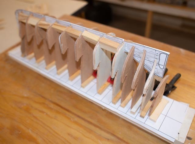 Here we see a from the stern. the blocks are only dry fit at this point.
-
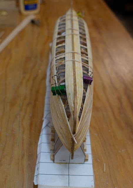
6.
 Here we see the dry fit from the bow. it is obvious I need 2 more stations here as the shape change quickly.
-
7.
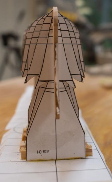 Looking from the bow we seem to be on the right path.
-
8.
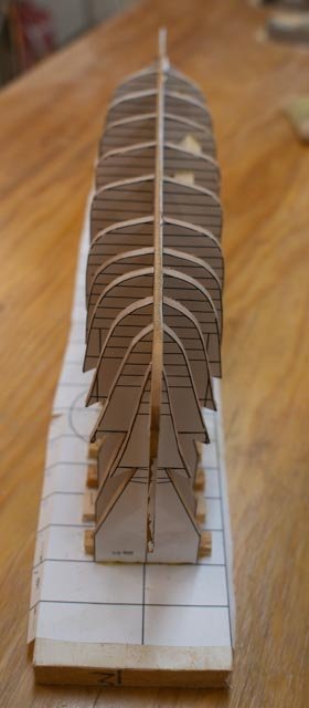 Looking down on the from the bow a question stays up. what about those 5 spaces that are a little over an inch….?
Next time we will get the bow and stern blocking done, do the fairing and clean up and figure out what to do about those spaces. I think I need more stations…All for now
-
1.
-
02 the Harvard story and selection process.
If one has seen my builds, they realize to me it is the story. The combination of the research the preparation and giving of talks and yes, the model as a prop to help tell the story. The story here is evolution of steel hull fabrication beginning in 1916 in this yard [ our town] and the emergence of power large size draggers / trawlers to the new England fishing industry. One reason I chose it is that I know absolutely nothing about any of it…..so let’s go.
What to build?
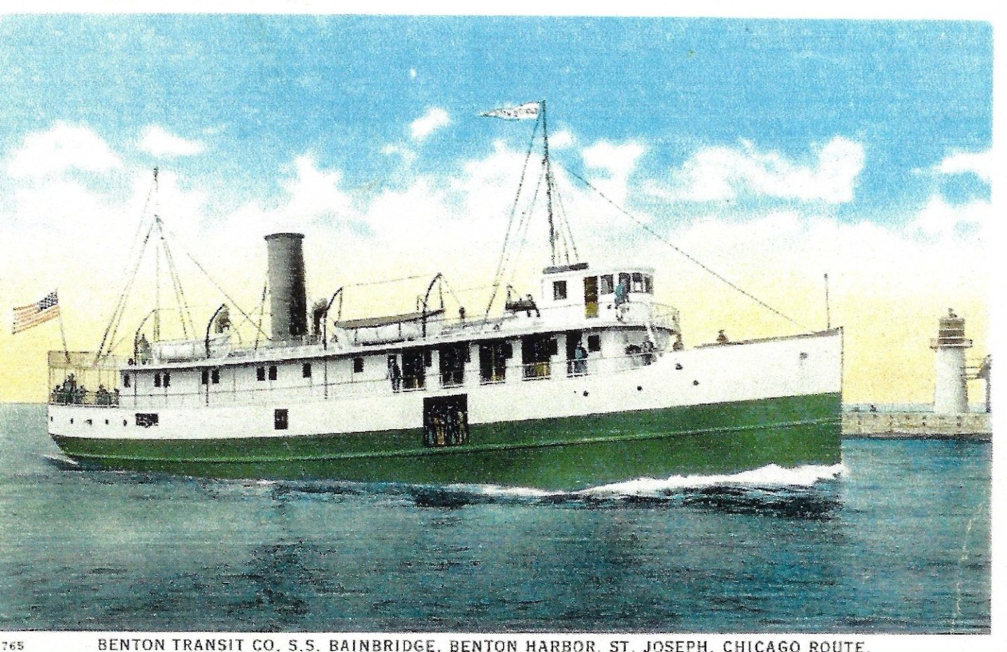
As part of our team effort digitizing our local Boothbay Region Historical Society, I have been focusing on what we have for records of the shipbuilding industry here. There is plenty…. After telling the first 100 years of the local industry two years ago, I am starting to move into the more recent 20th century. The first part was truly writing a multiple book report and mixing it with visuals and yes, a few models. This time I will find real people descendant from the main actors. I will therefore reduce each phase into one yard. I have already built a lightship, the Overfalls, which the launched at the end of The Rice Brothers’ run in 1950. The yard closed in 1955. I want now to build something at the beginning of steel. The Lightship Poe 1916 started the steel process and was in that hunt. I already did a lightship, and this story is about the yard, not one type of vessel. On their exhaustive list of builds we find several “beam trawlers”. Or were they draggers or. ???. On we go. One was converted halfway through hull construction and became a passenger vessel in Chicago, Mackinaw, and Lake Erie.
Looking through the list of early trawlers we have several and they were all about 139 feet long. The first was L M Winslow launched in 1918, and the second was AA Mills launched in 1919. Two more were started at that time but were stopped due to financial issues in the fishing fleet. The third [ still looking for original name] was renamed Bainbridge and converted to a passenger ferry boat. She had quite a life and was renamed as Erie Queen and Algoma II at different times. Another trawler Fabia was launched in 1920. After the Bainbridge was converted to a steam ferry she was launched in 1921. The Trawlers Fisher and Seiner were both launched in 1922 and finally Harvard [ previous started as the Arnold T Rice] was reactivated after sitting in the yard over 3 years in 1925 and was completed in 1926.
The beam trawler Harvard had an interesting life. She started with the General Fishing Corporation of Boston and fished up until WWII. She was sold into the coast guard; was lengthened 139 to 179 feet and renamed Bellefonte. In 1946 she came back to be de-armed and recommissioned in the fisheries department[ now NOAA] as the Albatross III. She finally ended her known carrier in 1959 when sold out of service to the Island Steamship line, Hyannis Ma.
I think we have a winner…..now some visuals
01
 here is the new Lightship Poe that was launched in 1921.
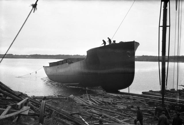
02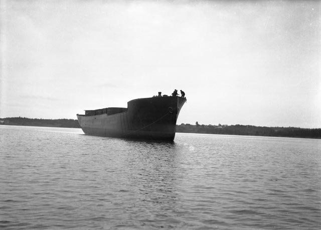 here we see the first launched beam trawler L M Winslow. We have lots of photos of this and the others as they went overboard.
03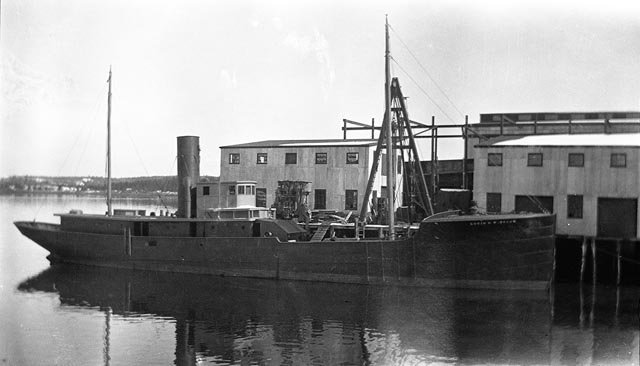 here we see both the Poe and Winslow beside the dock continuing their post launch builds.
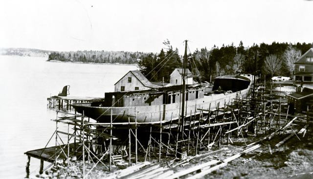
04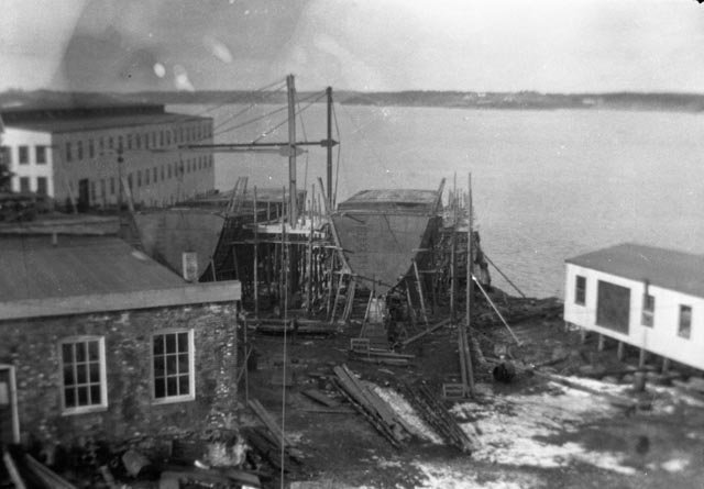 here in late 1919 we see both Harvard and Bainbridge side by side. A few months later as the hulls where mostly complete work was stopped.
05 a &b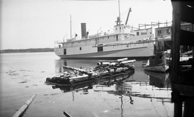
Here is the Bainbridge, a converted second hull to a stream ferry in 1921 and secondly as a ferry in the great lakes in 1923.
06
 there are two of these pictures and they are very much alike. One in 1921 when work stopped and this one in 1925 as work resumed. She was renamed Harvard at this time.
07
 yippee here Harvard is launched late 1925.
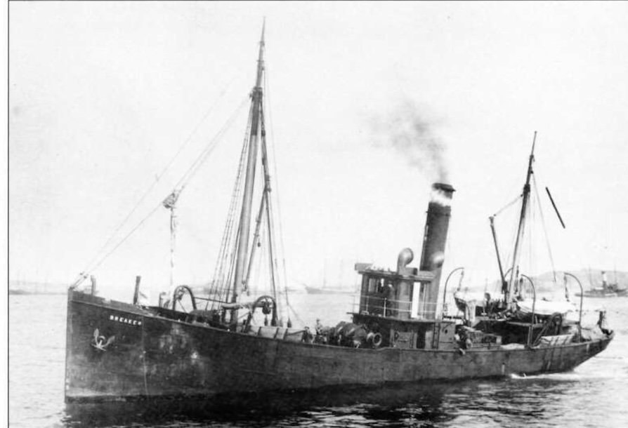
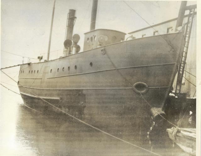
08 here is an internet picture of Harvard. I hope to find more.
09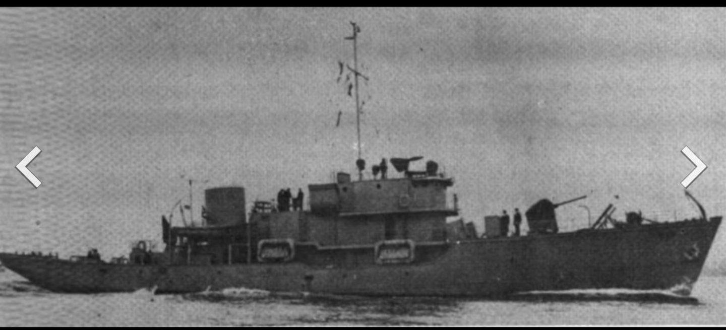 here we see Harvard renamed Bellefonte. She was lengthens and armed by the Navy of the coast guard.
10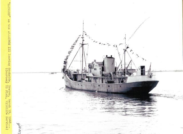 here she is again in 1946 steams out after a second refit to become the fisheries vessel
11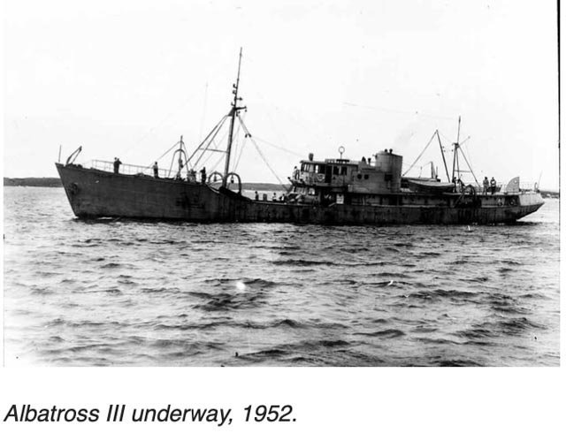 here is Albatross II as she is under way 1952.
12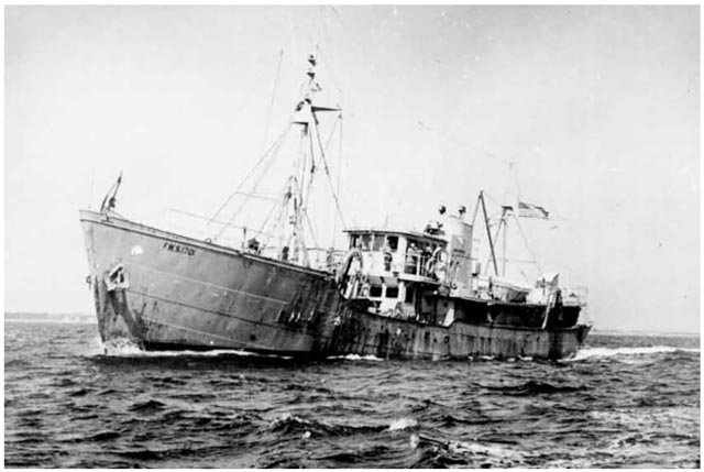 here she is again in 1958 near then end for that era.
The trail dies away. In 1959 she was sold the Nantucket Ferry line. That service was apparently taken over by the state in 1960, and their records start there. I have a friend in the guild with connection to Mass ferry service and I plan to ask him to help.
So now we know what we are going to build, the next question is how. What drawings etc. fortunately, we have an answer next time.
now it is fall in New England, and we need to get enough leaves blown to work inside and get going on this new adventure.
Cheers
- FriedClams, Retired guy, allanyed and 4 others
-
7
-
-
Building log for beam trawler Harvard
01 The beginning
I am in the middle of a deep dive into the study of one our Boothbay Region shipyards, most often known as Rice Brothers. As part of that study, I will likely include three builds and this one is the second. The Rice brothers’ father started building smaller boats about 1892. As the three sons came of age, they dove into ship building and took over from Dad. They formed the firm of Rice Brothers by 1903 and with three brothers expanded quickly. One Brother Frank split away in 1906 and continued on the property with a lumber yard, small boats service, cars and several other ventures. By 1910 the main firm was making their own small motors. They also set up a production capability making multiple class boats, both sail and motor. The traditional Maine built schooner based workflow continued as well, and in 1912 they launched the B B Crowninshield designed aux schooner Adventuress that sails today out of Port Townsend, Washington.
Let’s see what’s up.
-
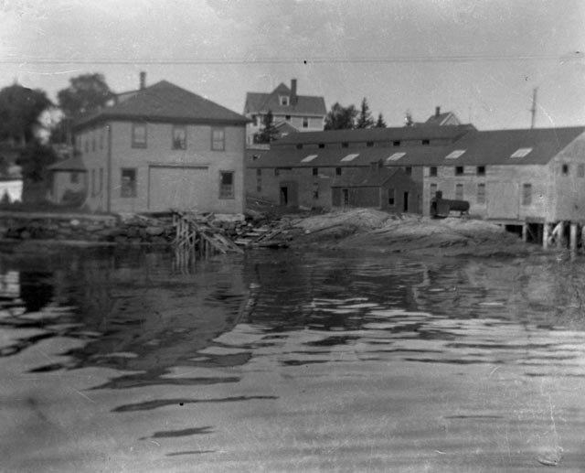
01
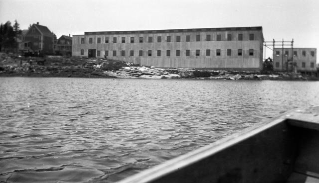
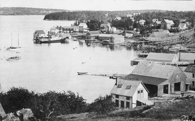 here we see a 1903 panorama of East Boothbay, Me. On the left we start with Race point with a pier for the steamship Enterprise, next we have the properties that were changing hands from Murray to the Rice family starting in 1892. The small yard was on the far side but quickly took over the whole pier where the steamship landed. Next on the right is a mixed area of sail loft, mast/spar maker, another yard that had been active since 1840. Next is the framing of the 4 masted schooner, Eleanor F Bertram being built by W I Adams. In the foreground we have the Hodgdon yard where many schooners were being built at that time.
-
02
 here we are looking south from the water to the large addition to the Rice brothers shop [light colored siding] built in 1910. This expansion allowed class boat and production line style of work.
-
03
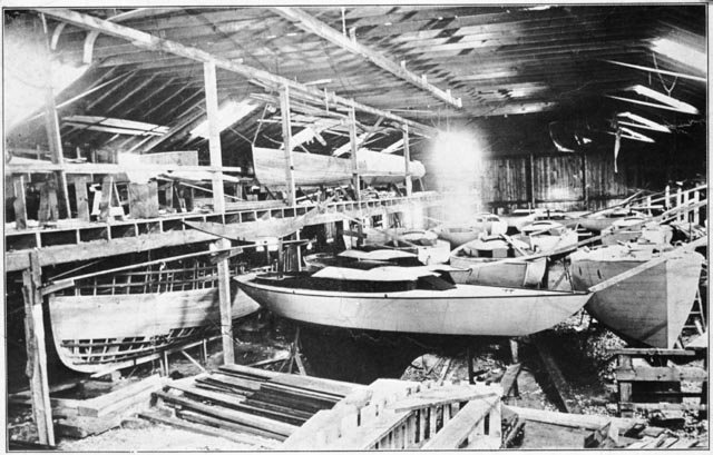 here inside we see a whole fleet of 30-foot racing schooners being built. There are similar photos showing runs of their motor launches and other yacht club one designs being built as a fleet as well.
-
04
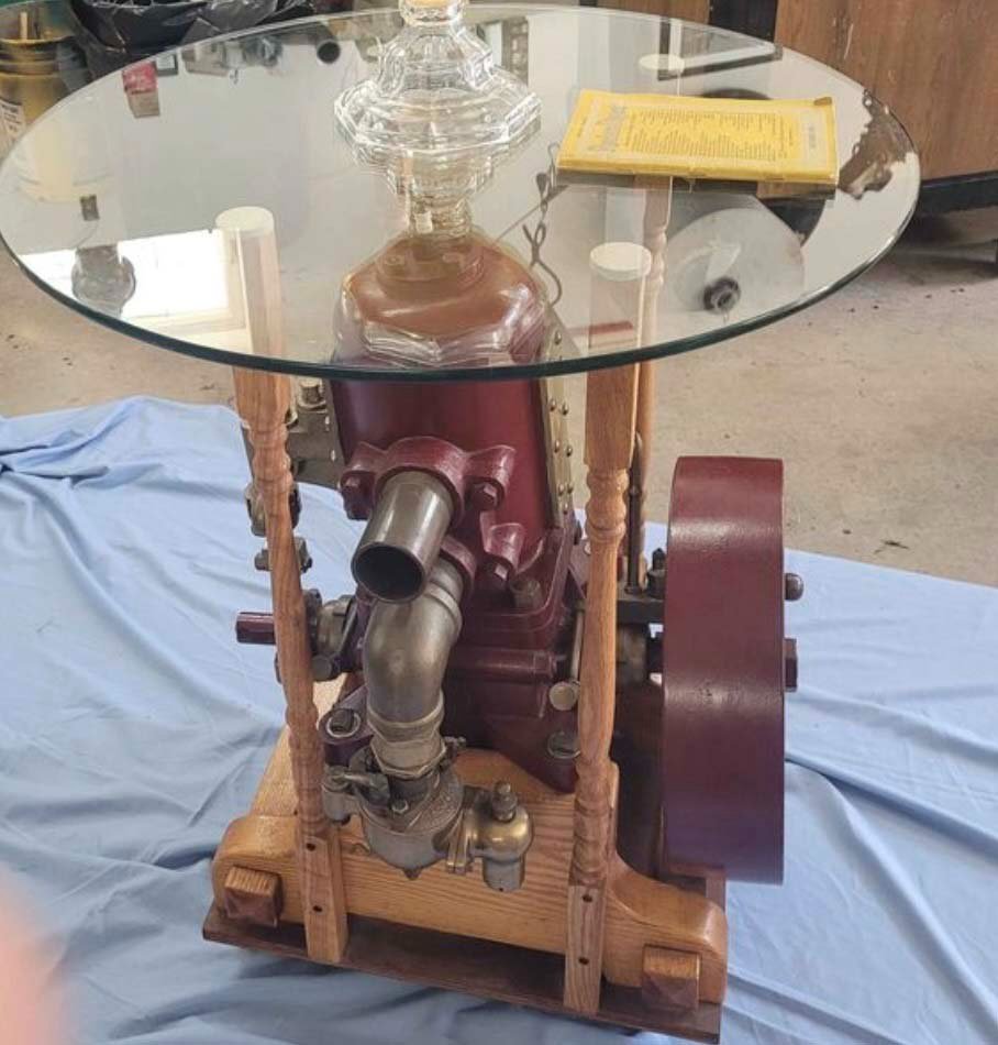 here is an opportunity right now on Marketplace to buy a 1901 Rice brothers engine made into a table.
-
05a &b
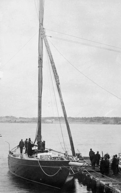
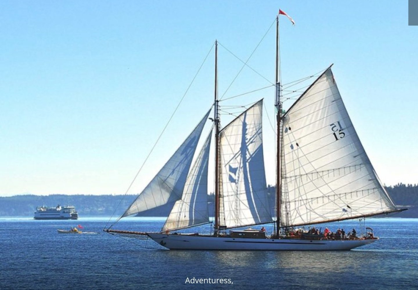 here is a photo of Adventuress as she was launched in 1912 and a recent internet photo of her as a featured schooner in Washington state.
In 1916 they got their first order to build in steel. The Lightship Poe. She was well along, and orders came in for Steel draggers too. There were ultimately 6 large steel hulls to build.
-
6
 Here we see further expansion in 1916 and preparation as they won their first contracts to build in steel.
Oh no a huge fire in the summer of 1917. The losses were terrible. More than 40 completed boats ready to deliver went up as they were stored inside. Outside the lightship Poe was totally ruined.
-
7.
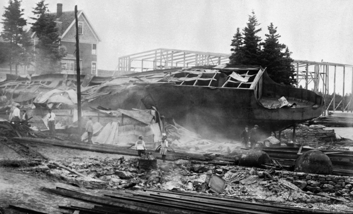 here looking across the smoldering hull we see the empty building frame.
-
8
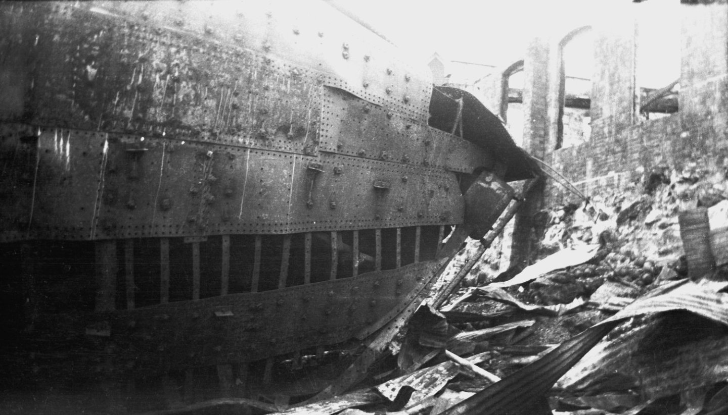 look at the deformation cause by the intense heat.
-
9
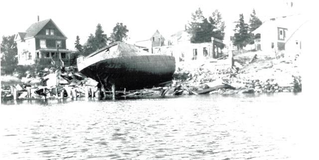 from the shore it is clear a new start is needed.
-
10
 we end this chapter on a good note as we see the following year the shop was rebuilt and work continues.
All for now
- GrandpaPhil, Rik Thistle, Canute and 7 others
-
10
-
01
-
Thank you for sharing your own research and dropping by. It is interesting in just looking through the images you added the variations in the masts and lighting. There is obviously a whole story out there on the evolution of the technology on the systems. I'll leave that for others as for me it's great just to celebrate that three of them were built here and remain on display 70 plus years later. Of course it is the TLC of many out there that make that happen. I plan to visit one of them this November as I have never done so before.
cheers
-
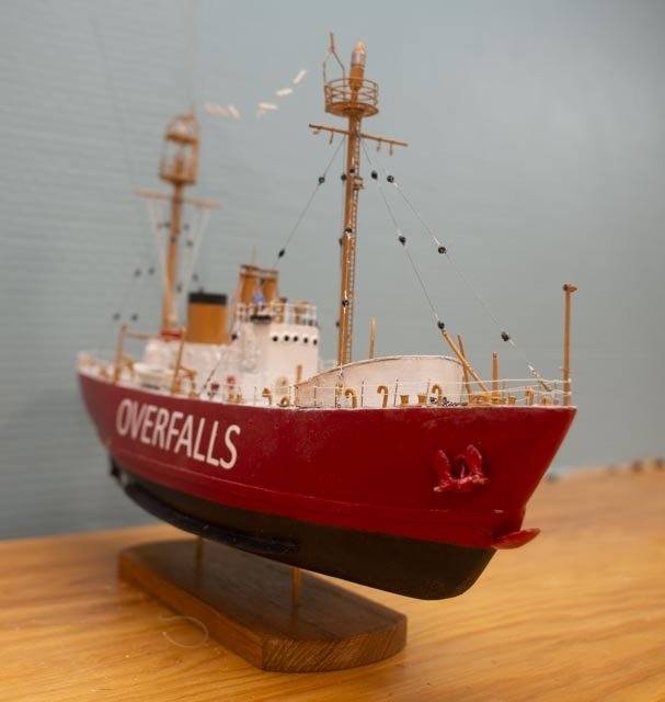
post 8 sort of done with model phase
This posting is a transition on this build. My project typically includes lots of research and a resulting power point presentation or Museum slide show for our local Historic Society. As I have said before, to me it is the story, of which the model is only part . This story is of the Lightships, and full chapter of the Rice Brothers of East Boothbay. I shared some stuff in the beginning. As we are in the process of scanning / digitizing the collection we have many rabbit holes to follow. Rice brothers will consume me for years if I am not careful. there are lots of visuals we have to include as I go on.Today I share a few images of my struggles and a catchup overview. We then have the inevitable punch list before closing in perhaps one more posting
Struggles
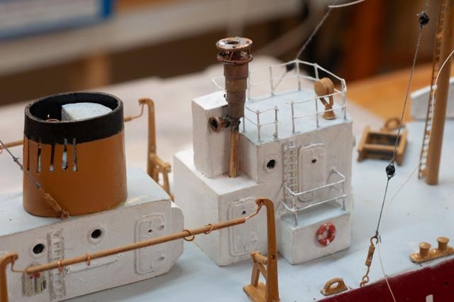
I worked on radio antenna cables that seem to be way over my pay grade, and one completed one more soldering job to make my interpretation of the foremast pin rail.-
1
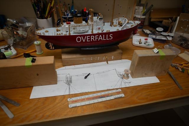 here is the layout from the 1950 coast guard plans of the aerial. The Nantucket kit came with shiny silver like thread. Boy is it finicky.
-
2
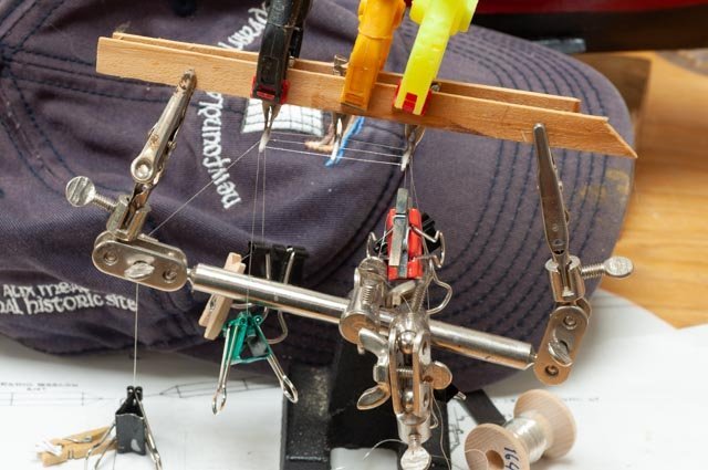 here is my first of three set up jigs to try to make the assembly. This one failed miserably. I didn’t photo the others. What I finished with was suspending a metal ruler and using hair pins to hold things just off the metal so the glue hopefully would not make a mess. What is eventually on the model looks fine from 25 feet away. [ that suggests the next room] Up close it is twisted, and I cannot imagine how to make it straight with thread. If I were able to do resistance soldering of fine copper or other wire that might work. I played with the fine brass railing from the kit material but did not come to any conclusion as how to attach two pieces finely that are then in tension and suspended.
-
3
 here is soldering at a level I can do. It is my interpretation of the pin rail on the foremast. I showed the picture …post 7-2 that shows it on the far side of the mast. It is invisible but clearly projecting from the mast. I chose piping to match what can be seen on the main mast.
Progress
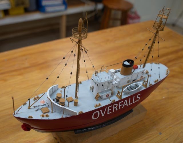
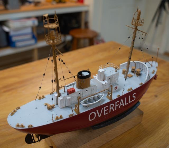
Open items include the foremast pin rail and lines to be rigged and possibly a case. I am debating flags too. There is a lot of touch up painting to do as well. That never seems to end for me.
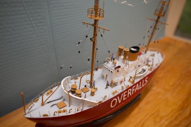
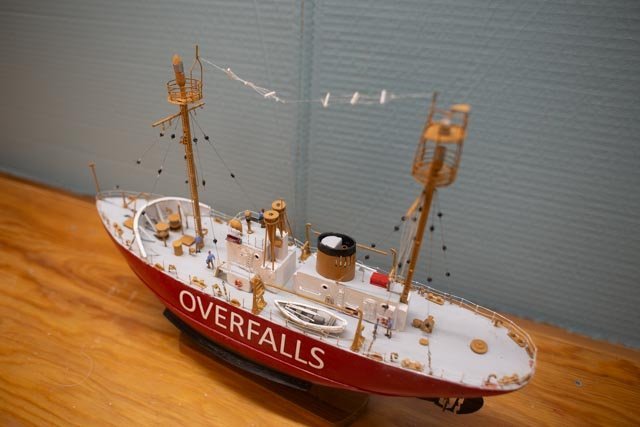
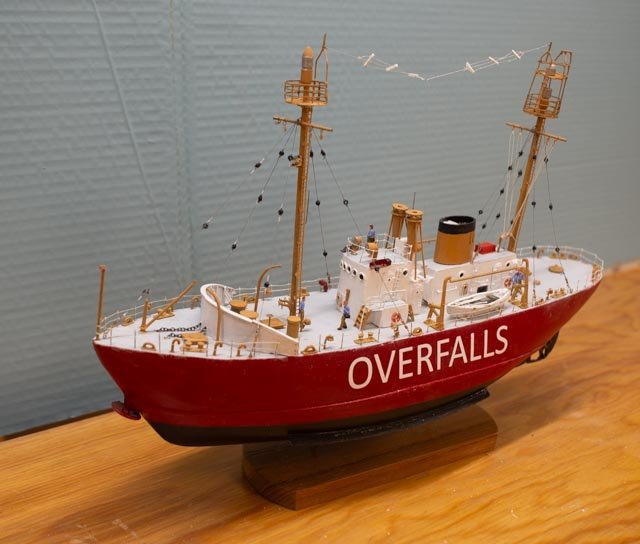
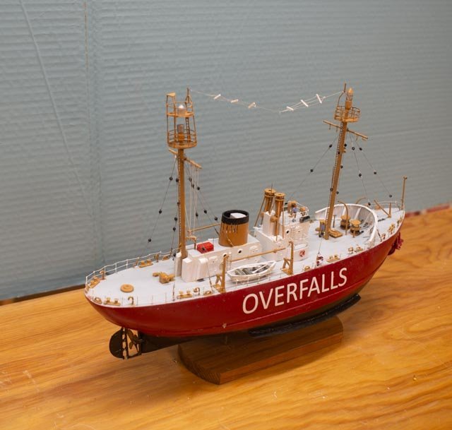
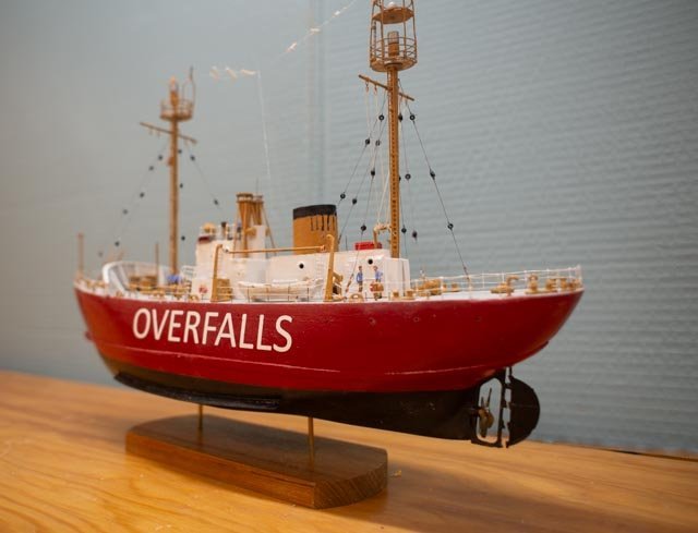
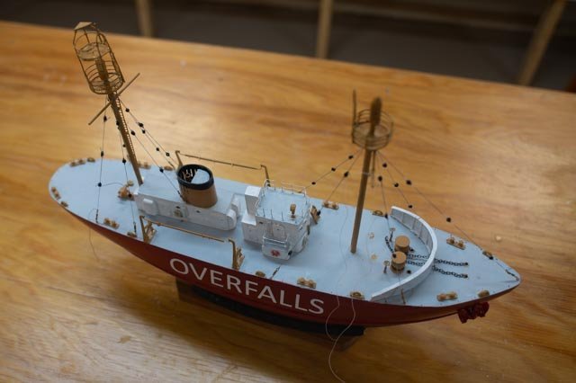
Here are 7 view of different angles.
Next steps
This build will rest for a while as I do the side-by-side story. There are hundreds of designs built by Rice brothers 1892 to 1955. I will do a final posting when the punch list is done and if I get a case. I tried to order it but am waiting. then of course the punch list.
As I tell their story there are a few more potential builds making a combined showing. Some options include:
1. Break Rock one of two identical John Alden Schooners launched in 1925. Renamed Bagheera and now 99-year-old Schooner sailing daily in Portland Me.
2. Harvard Built 1922-1926. Due to financial issues. It was a steel dragger, one of three. In WWII she was taken by the Navy increase in length and renamed Bellefonte. After the war she was one of the Albatross NOAA vessels.
3. Some other draggers. The problem is finding plans.... more later as I chase Harvard.
4. 1924/5 10 each coast guard Rum chasers. Look like fun but again, how to find plans?
5. WWII they built subchasers and mine sweeps. So many already exist I will likely pass.I believe my next build will be Bagheera if can get the plans. I have many on deck photos for the needed details.
All for now
- Canute, Landlubber Mike, ccoyle and 1 other
-
4
-
1
-
7 update on rigging and deck fittings
It’s been a while since much progress as we took a vacation. On the way home we dropped in to see Nic at Bluejacket, always a fun detour. He shared with me a few hints and then explained their new case kit systems. It looks great and I will be ordering one as part of this build.
I have gone ahead and replaced all the rigging with smaller lines and glass beads. The little black shine comes off of the beads, and a dab of white paint on the thread sort of says ‘SPLICE”. The beads are as small as I have seen.
-
1
 here we see from a few days back as I got the las lines redone. I am sure there is a good reason they broke up the stays and shrouds into so many pieces. As they were splices, I do not see any advantage.
Work on deck…I am working back and forth inventing things to match the photos. As always there are never enough views to explain everything. Let’s see what we have so far.
-
2
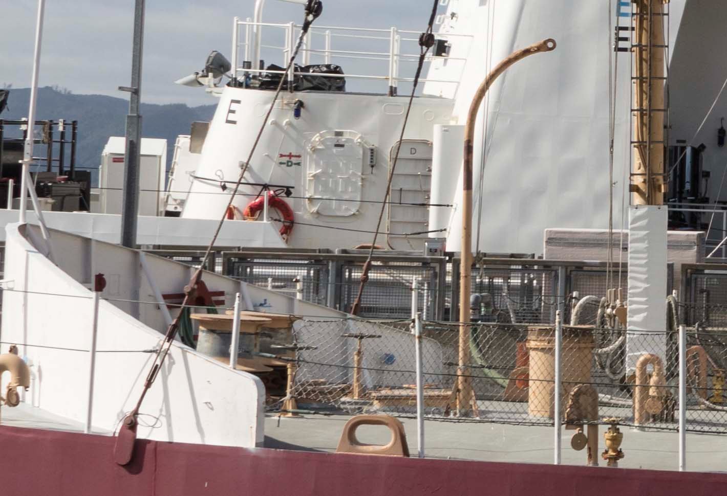
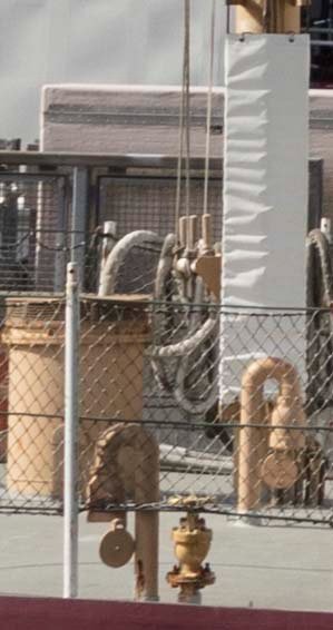 I start with a mystery and joke on me. Looking closely on this blow up, I was trying to figure where they tied off the lines from the foremast yard. Looking past the mast I saw a type of pin rail. It is painted the same brown tan color as other things, so I remain confused on where or what it might be. It must be attached to the mast. Is it just the rail itself welded?
-
3
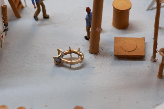
 I went ahead and made a pin rails stand so if placed it would be strong enough to take the lines. It seems much too big. Naturally there are no more photos I have seen of this area...... As to the lines, it looks like one on the starboard [ far side] is doubled to a ring giving 4 to one for heavier loads. The mystery on the foremast rigging continues. The solution is probably just to make a smaller and tighter rail with no outside stand/ leg and only be against the mast. too late to solder !
-
4
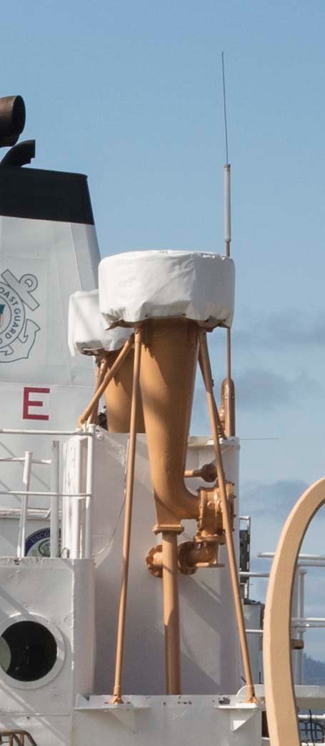 I am not positive but suspect these are the fog horns. The fan on the bottom blowing into the large chamber and open top. Well let’s assume it is and then figure how to make it.
-
5.
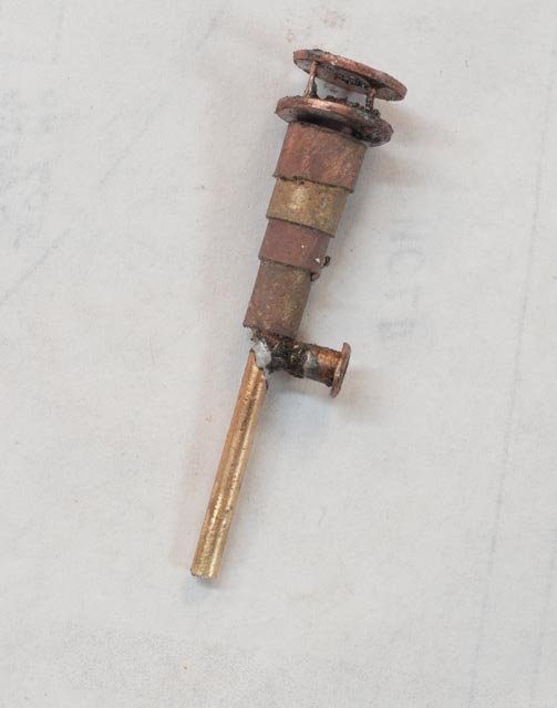 here is my approach. Four concentric tubes over a bent rod. Then two copper washers drilled, and copper wire soldered. I will fill with glazing putty and see what comes.
-
6
 here is a trial fit. Lots of little supports to make too.
-
7.
 I have found 6 closed chocks in my stash of unused parts from who knows where. I need 8. When I stopped at Bluejacket they said they had no idea where I got them. They make some, but not in that size. Well, I bent a brass rod into a u and passed it through a small plate and soldered. The shape is too round but close enough for the last two that I need.
General progress...Here are a few views of today’s status.
-
8
 The fore deck is getting close. I need braces on the water wall touch up paint and final step of rails. There are radio aerials and things to go and then the antenna wiring.
-
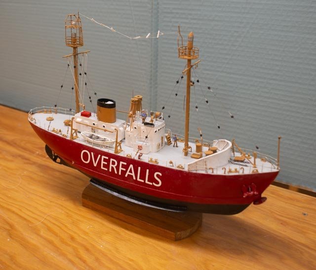
9
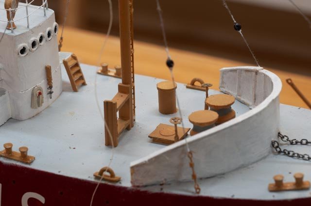
 mid and after deck is coming. Boats are in, and the raft setting partially painted. Lots more stuff to go in and then the rails. If you look closely there is a tie off rail forward of the main mast that receives all the lines from the main yard. Again, there are conduits to run up both masts and the lights and gear to figure out. The crew arrived this week too.
onward we go
-
1
-
6 mast tops and riggingI now have things in place or at least figured out...maybe.
First up is a humorous finding. The tops of the masts apparently kept changing in real life. The tops of Columbia’s masts today are the opposite of the tops of the Overalls’ masts. The 1950 plan shows a single platform on the fore mast and double platform on the main mast. I have been focusing on Columbia because of the quality of the photo. It is the opposite of what I am supposed to be doing. I got myself totally confused…..Let’s see below.
-
1
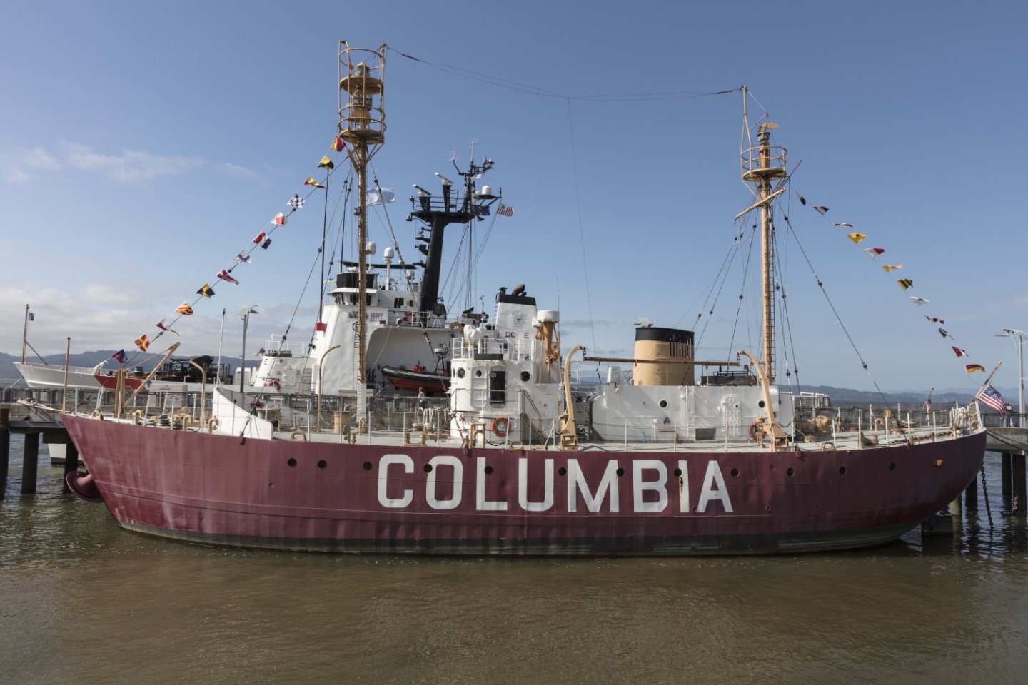 here is Columbia today with a double deck platform on the foremast. Several photos I have already posted show this arrangement. So I changed things from the plan to this way….oops
-
2
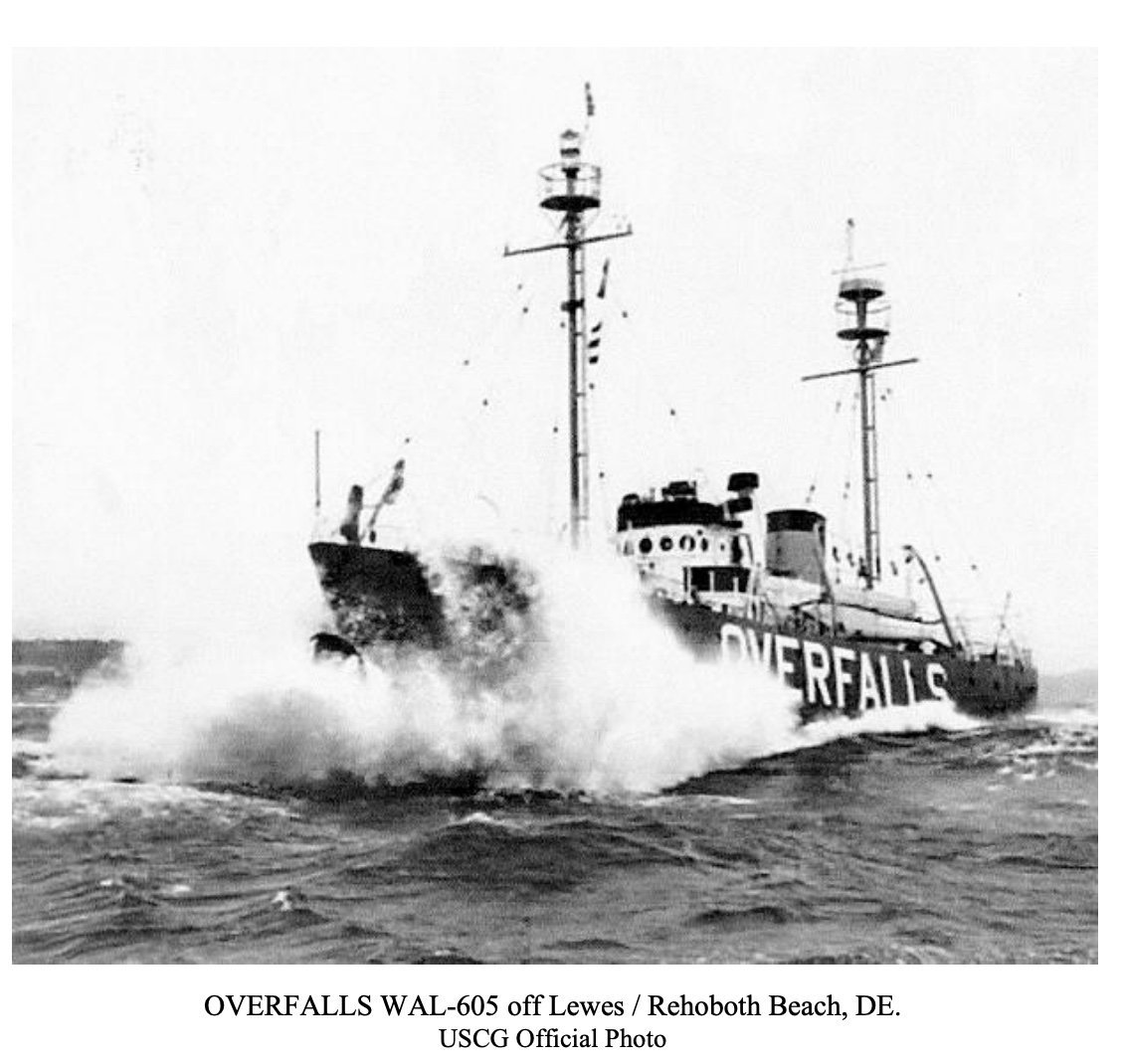 here is Overfalls before she became Relief. Her mast tops agree with the plans, the double deck is the main mast. I have been going nuts working from the plan then seeing the opposite. I have switched them. More than once. Last week I unsoldered and resoldered the single deck as I was convinced it was done wrong....oops. Also, I found the mast ladder to be on Port side not starboard. Oh Well I am going with the plan and Overfalls picture. That means rework again, but since I figured out my problem hopefully only one more time.
Rigging
I got the rigging done….I thought anyway. The good news it was sort of right. The bad news is I think it is out of scale a bit. I used the 2.5 MM bullseyes, the smallest I could buy. I could obviously have deleted them but thought I wanted to show all the little section of shroud / stays. I note after checking other lightship models ignore this element and that is why this one seems so odd. The cables are all spliced and wrapped with white tape…I thought I wanted to show that too so spliced the connections using white thread. Maybe it would look better when the rails are in place and other components fill in some of the deck. I will need to decide however before moving ahead to rig both the yard arms and radio wires if I need to go smaller.
-
3.
 When I studied this detail photo, I felt the shroud was clearly 1 inch or more thick and the bullseye fitting nearly the size of a person’s head. I thought it would be ok. 2.5 mm translates to 1/10th inch or about 9 inches.
-
4
 here on the main mast we are all in. The overall look in this photo though has me worried…. It just isn’t right. It is too busy.
-
5
 here after setting one more of the bigger shrouds, I ran the other foremast shrouds and head stay in thinner thread and black beads. No splicing. I think it looks better….Not sure yet what to do.
-
6
 here we see both masts. I think the bigger spliced lines and bullseyes must come off. Also in this view, the boat davits are not perfect, but I plan to move with the kit pieces and a few adjustments. Adding the spreader pipe and rings helps.
-
7
 This blow-up of Columbia gives us the details for the foredeck. The windless is huge drum like piece. It has the anchor chain wrapped below. There is another davit to add with hatches etc. I also note the large chocks.
-
8
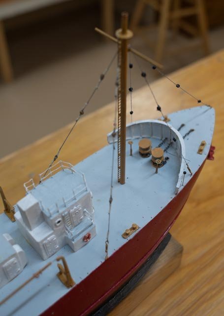 here we see the anchor chains and windless roughed in. I decided to turn some wood and paint it and move forward. I envy the metal work artisans who would have turned these pieces in brass. I did solder up the break handles in brass.
All for now
-
1
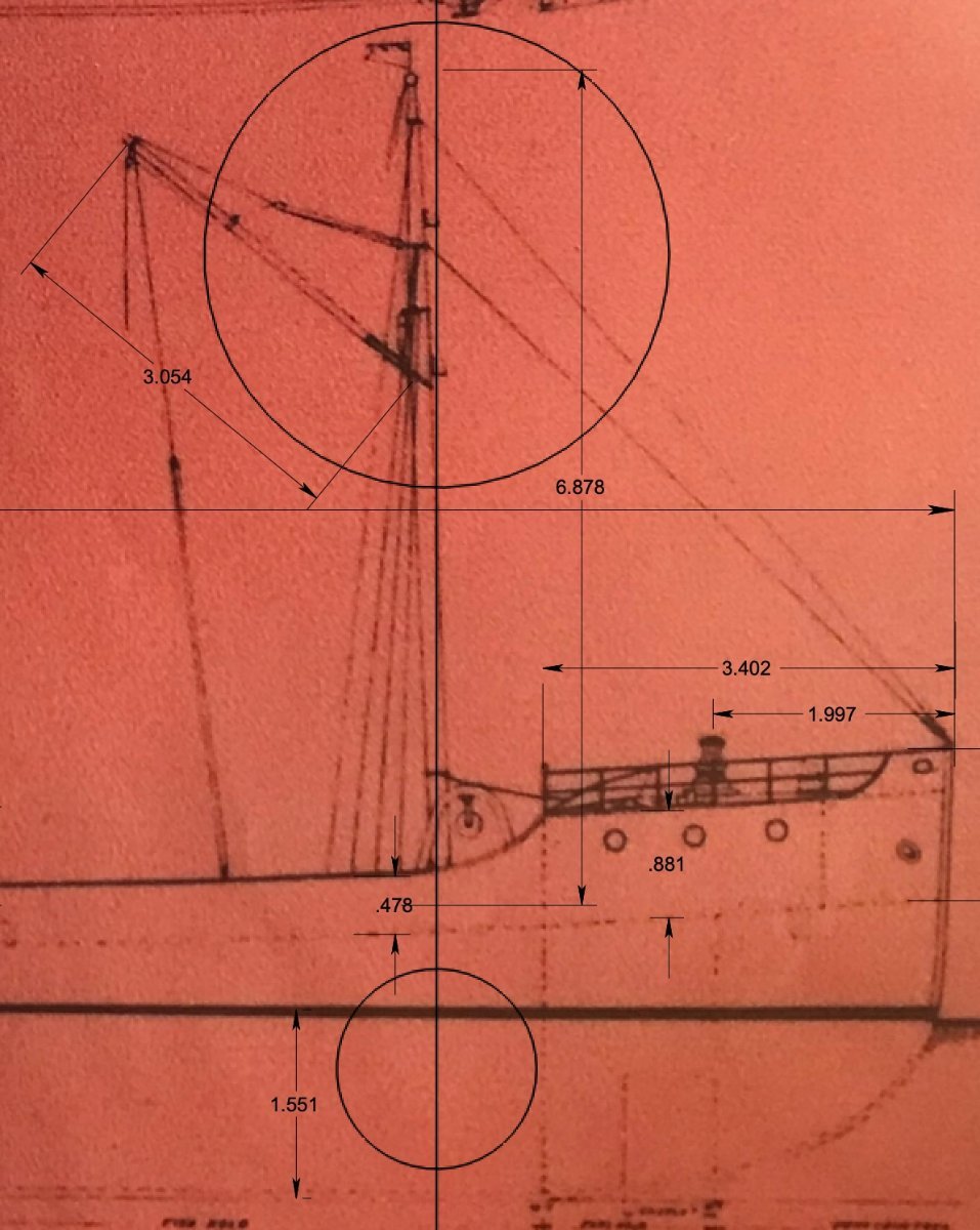
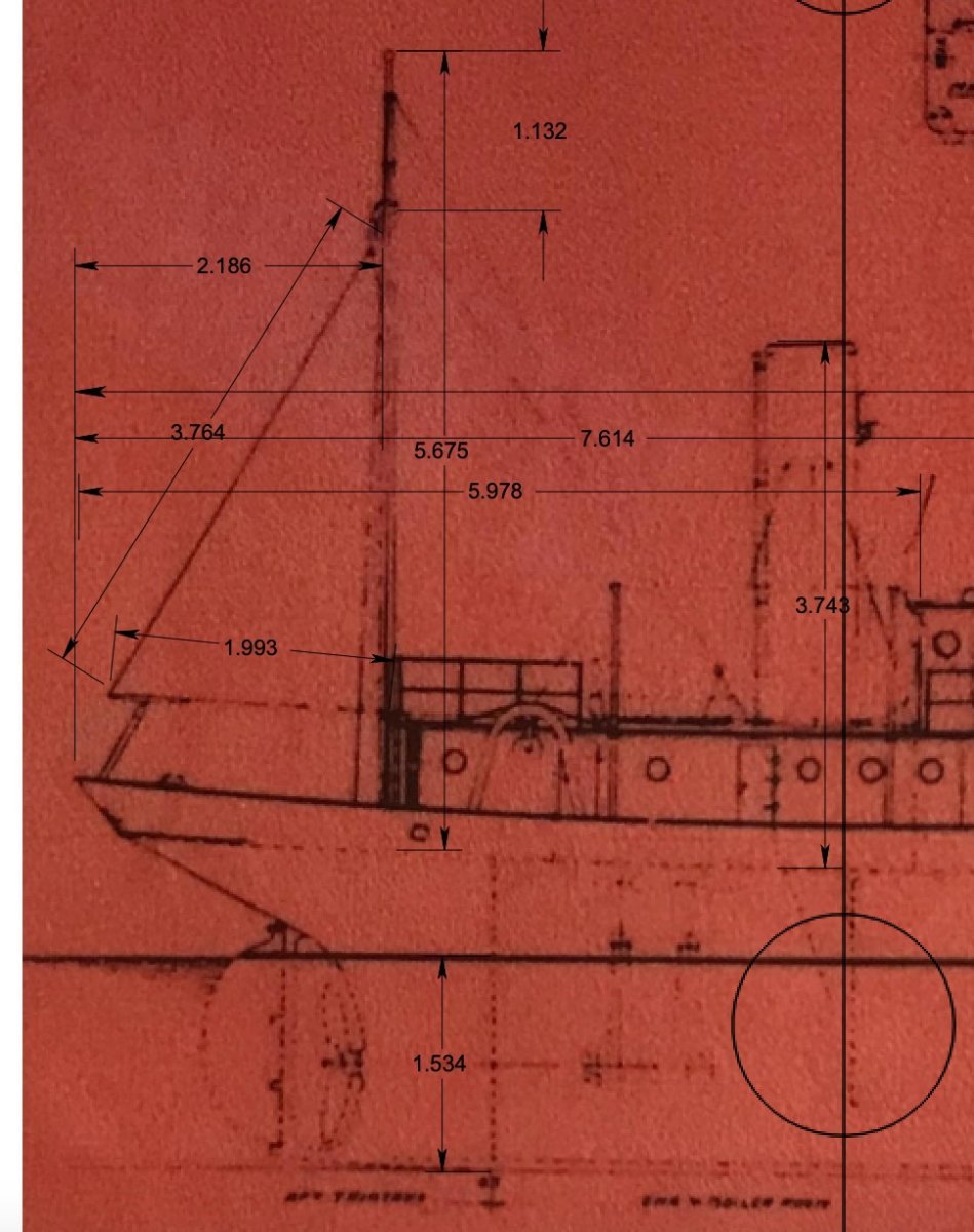
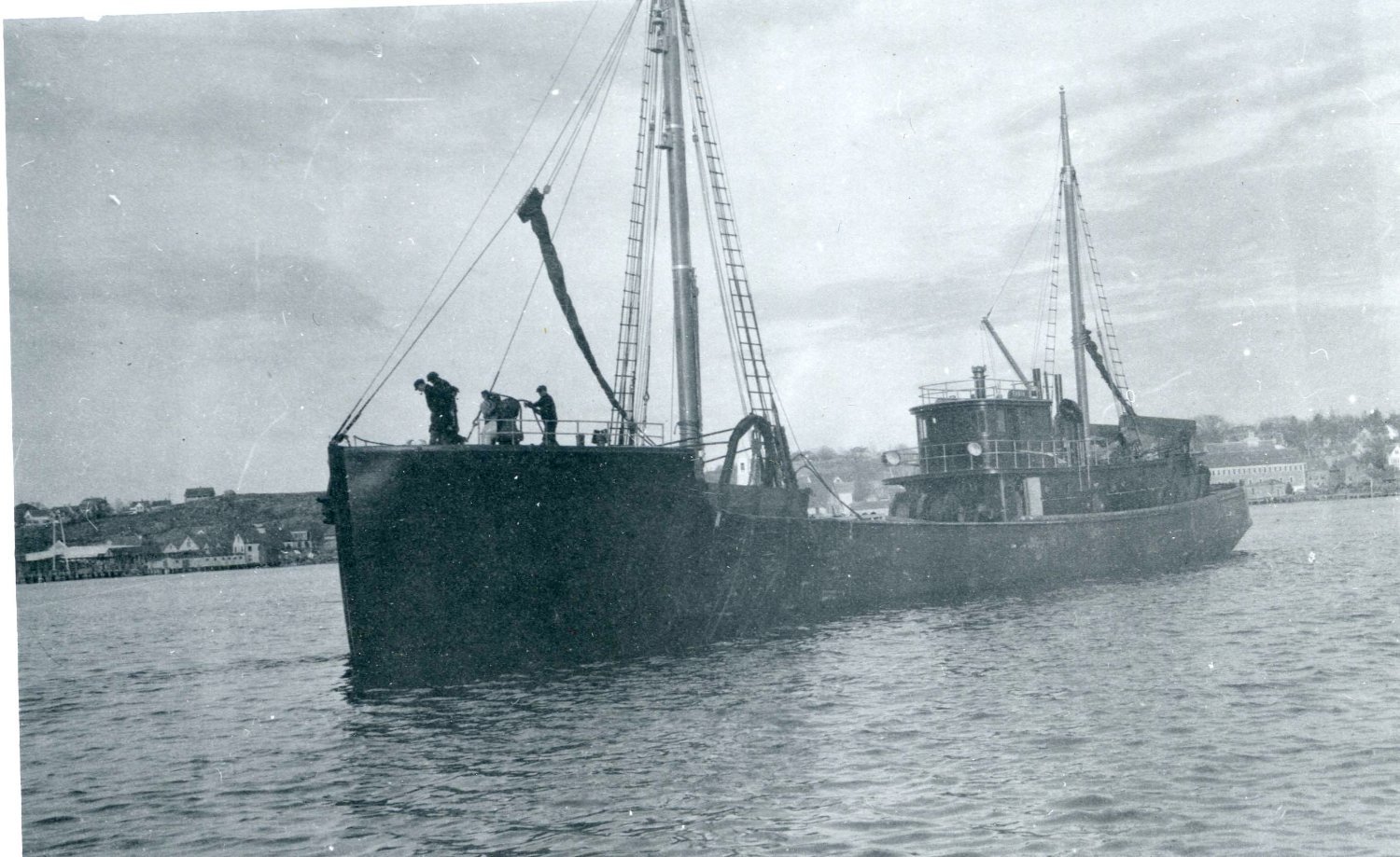


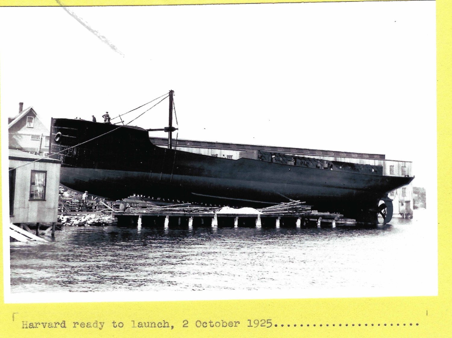
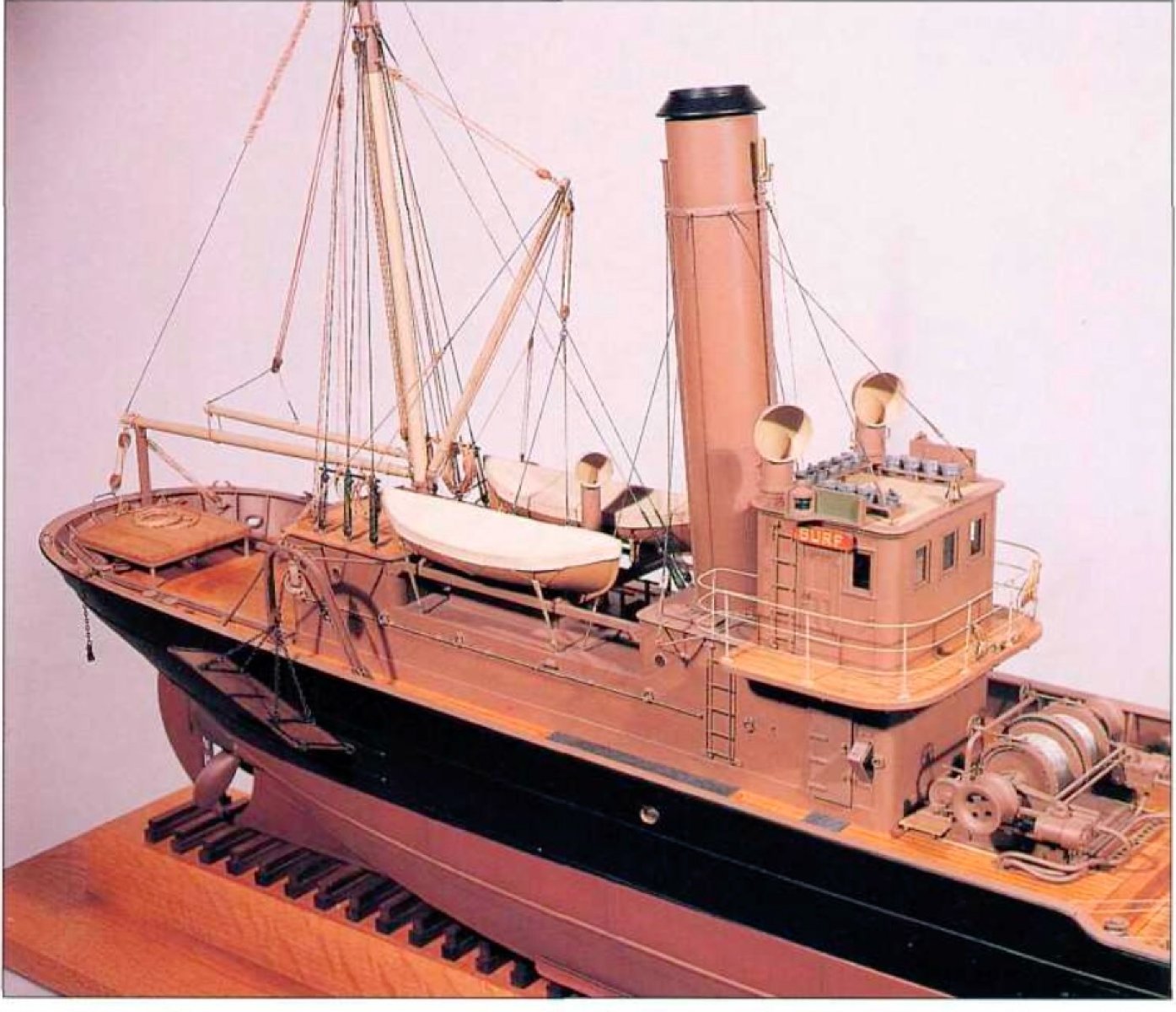
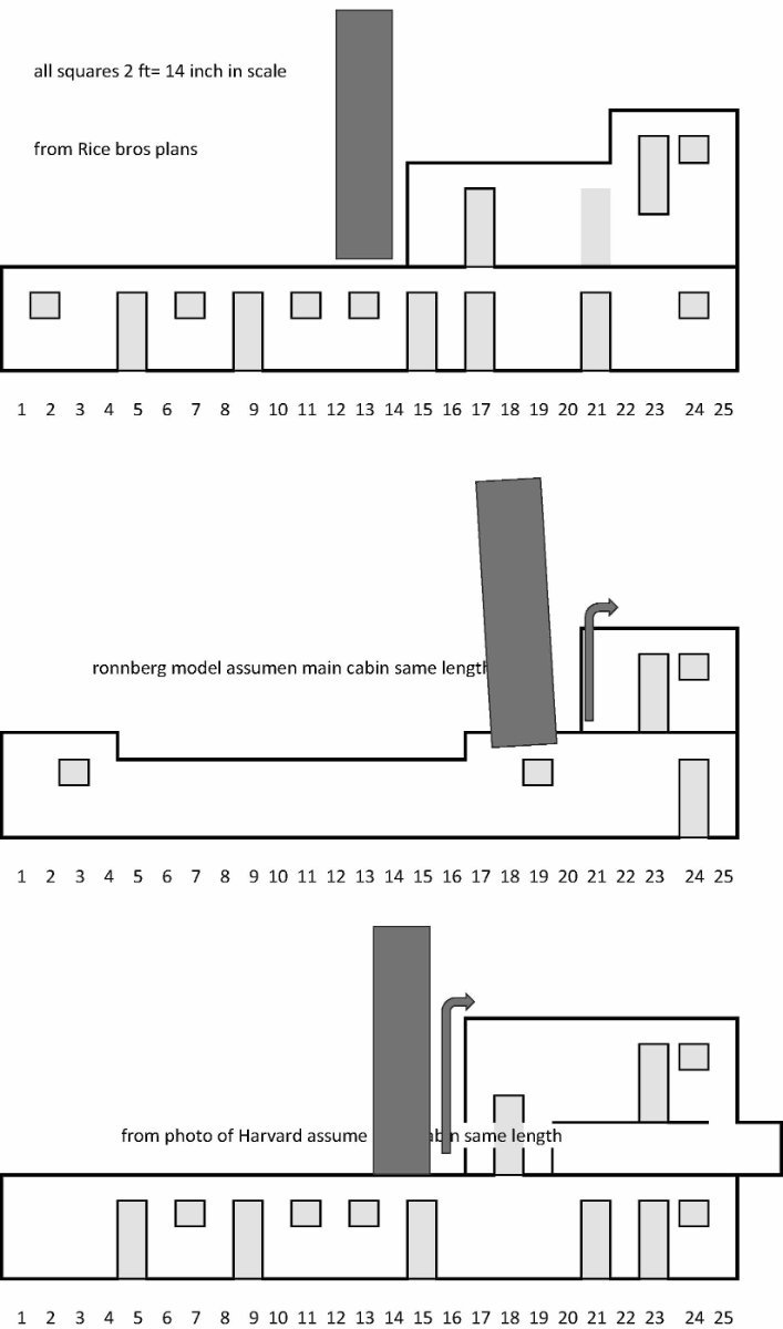
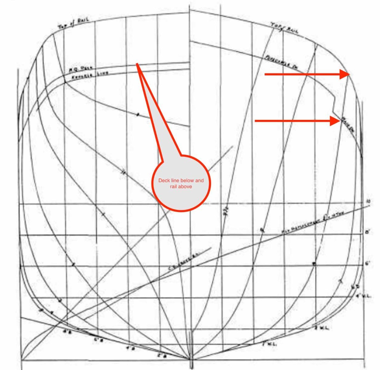
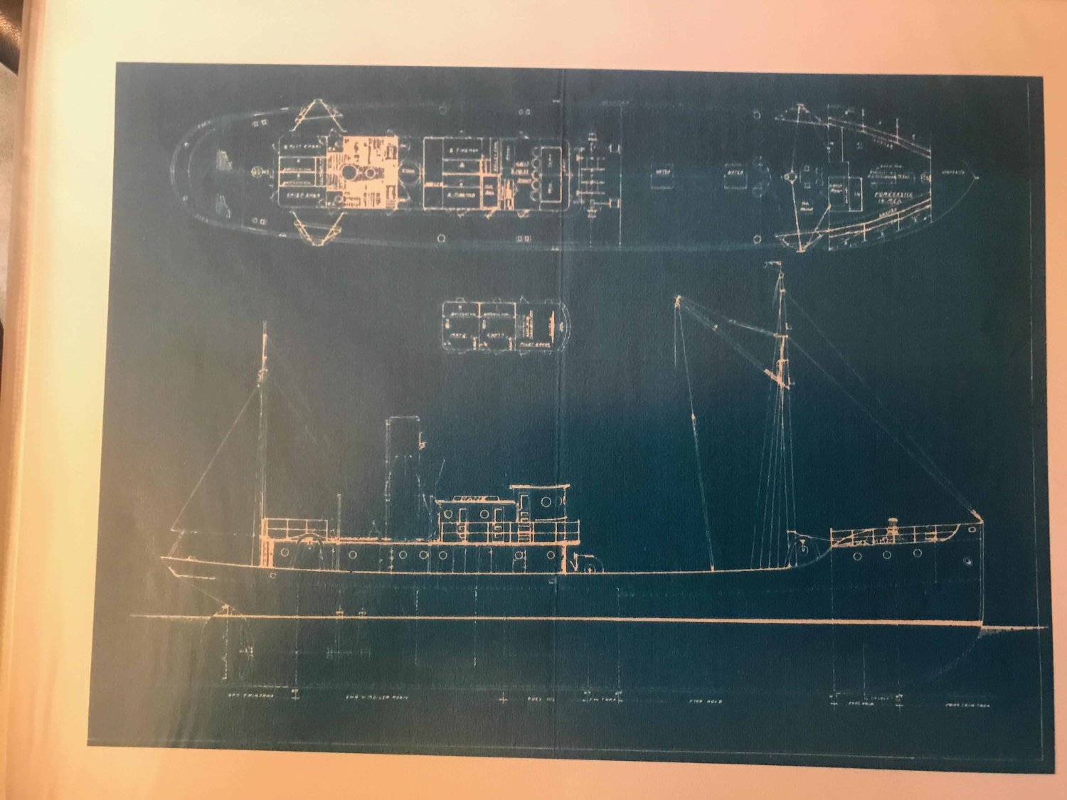
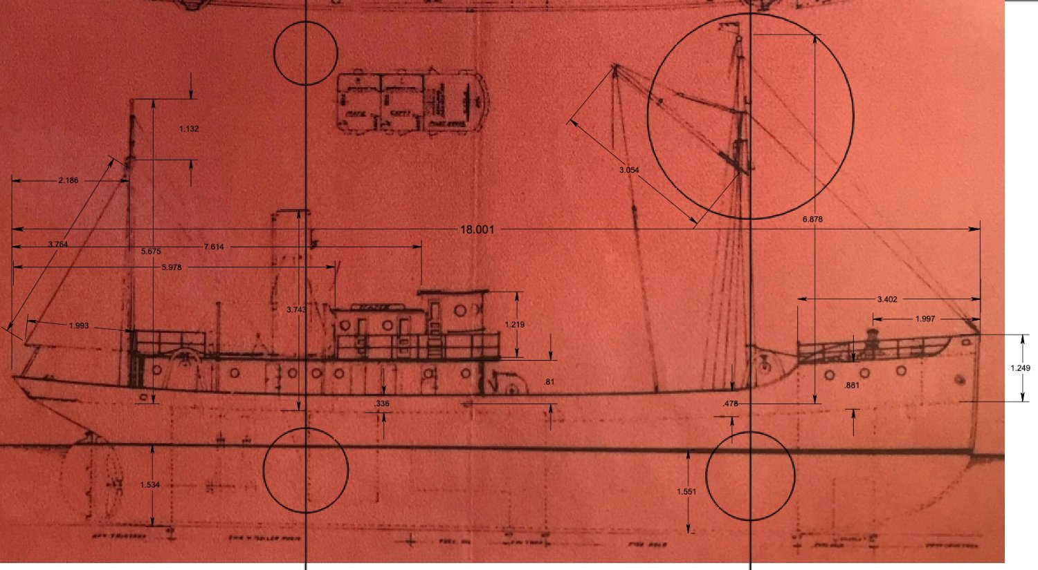

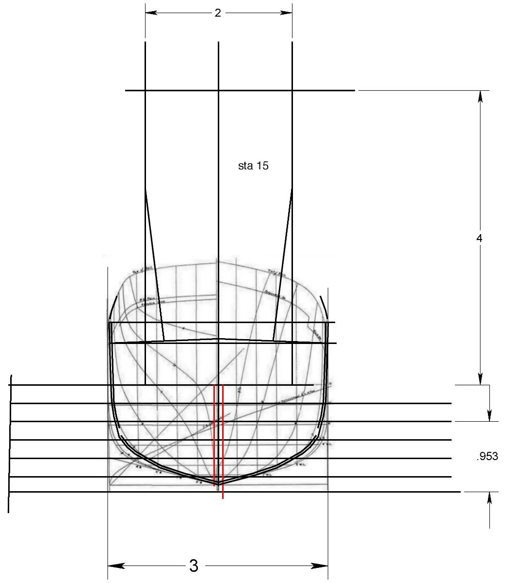
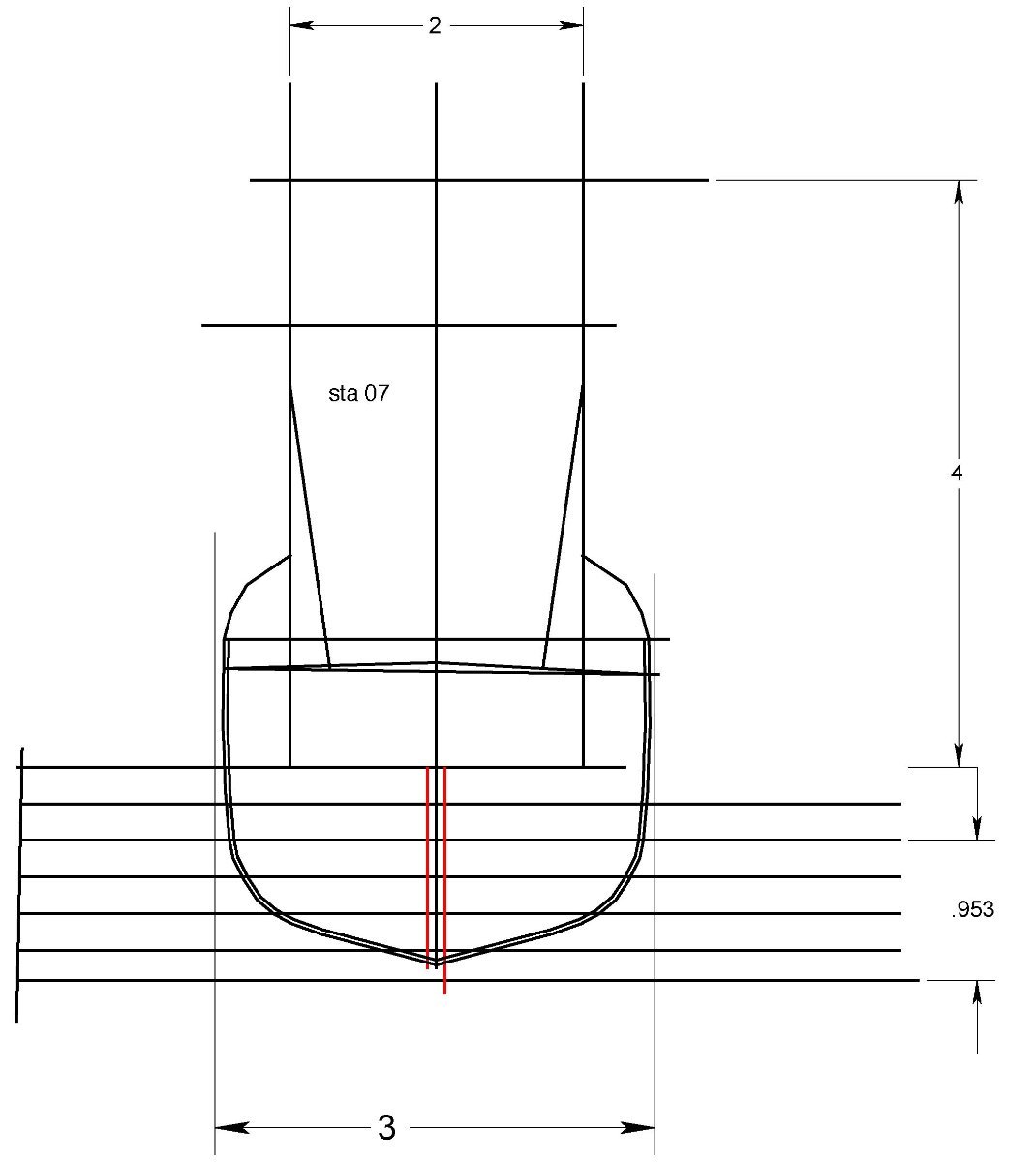

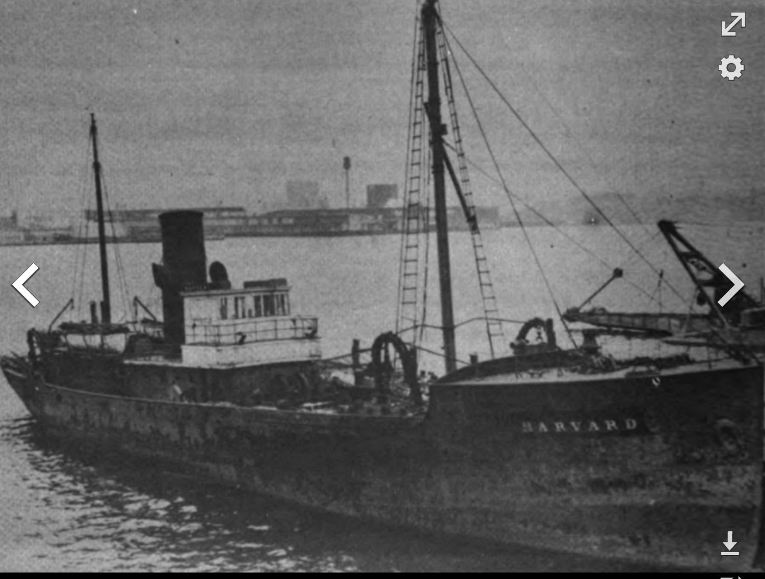

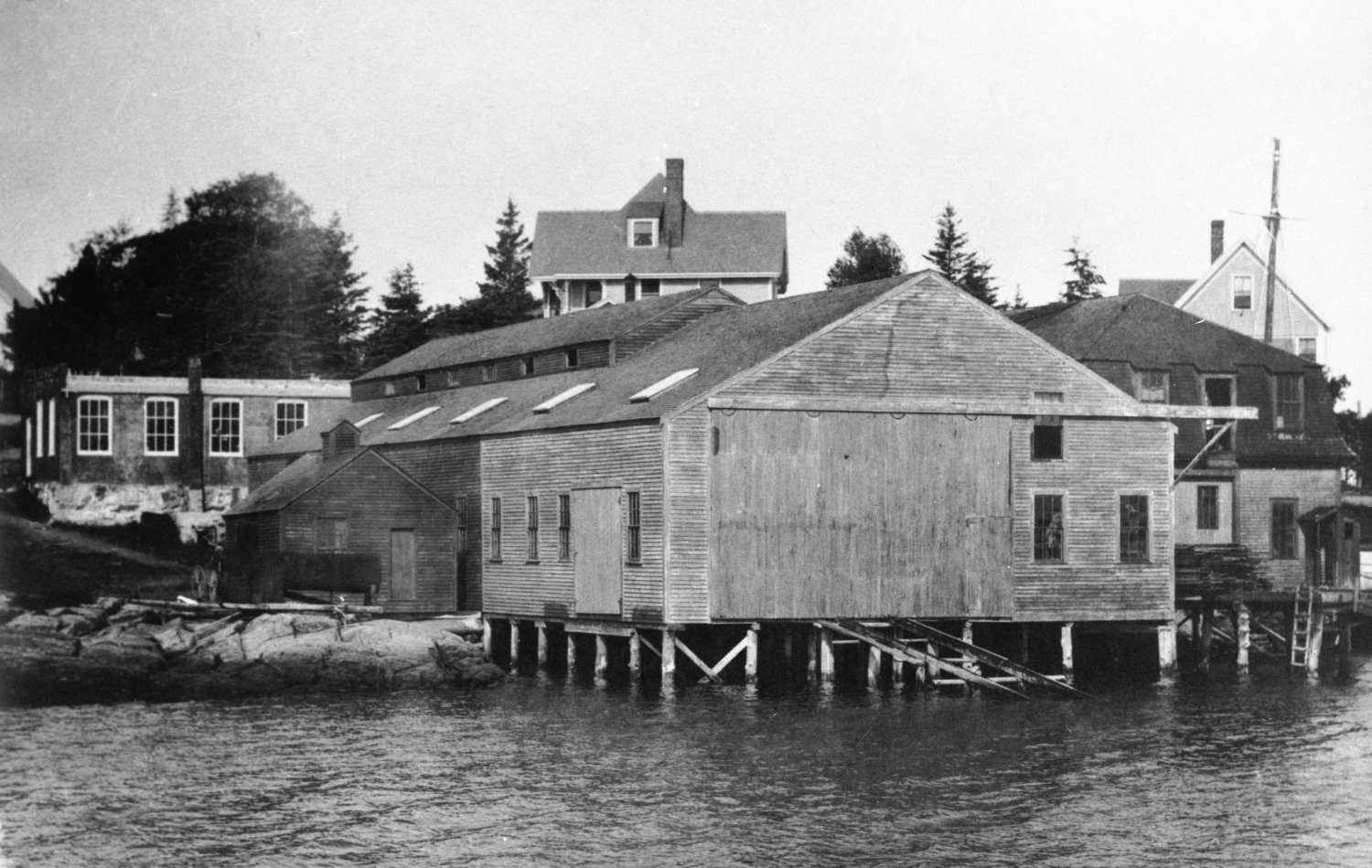


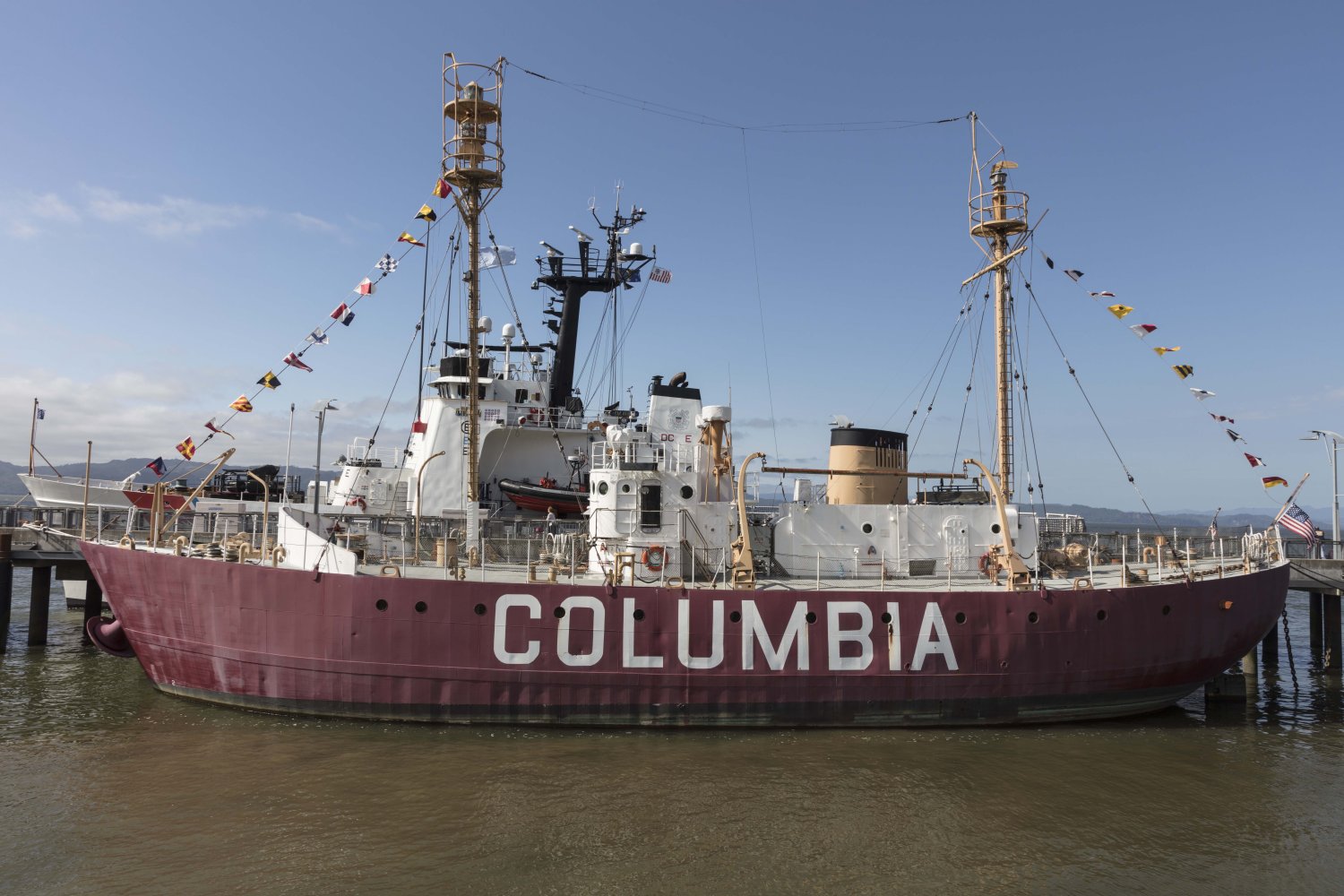
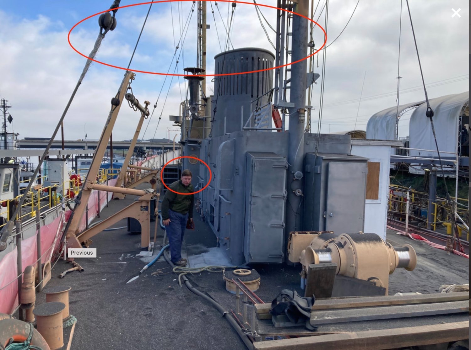
Beam Trawler Harvard 1926 by Jond - 1:96 - early steel hull by Rice Bros
in - Build logs for subjects built 1901 - Present Day
Posted
Jerome
thank you for sharing that great reference. the more I look, the more I see i do not know much about fishing. One thing I learned through reading during this build is to visualize all those cables moving and fish jumping around on deck and the noise, the rolling and the cold and wet and the....it doesn't end. I am very grateful to drive about a mile to the local grocery store and find fresh fish right there.
I just received 18 3 ring binders chocked full of the complete Rice brothers collection and will be fully focused on going through those and making up a slide show / talk series on their incredible history for our local historical society. I hope I can do them justices.
cheers
jon.