

Navis Factorem
-
Posts
240 -
Joined
-
Last visited
Content Type
Profiles
Forums
Gallery
Events
Posts posted by Navis Factorem
-
-
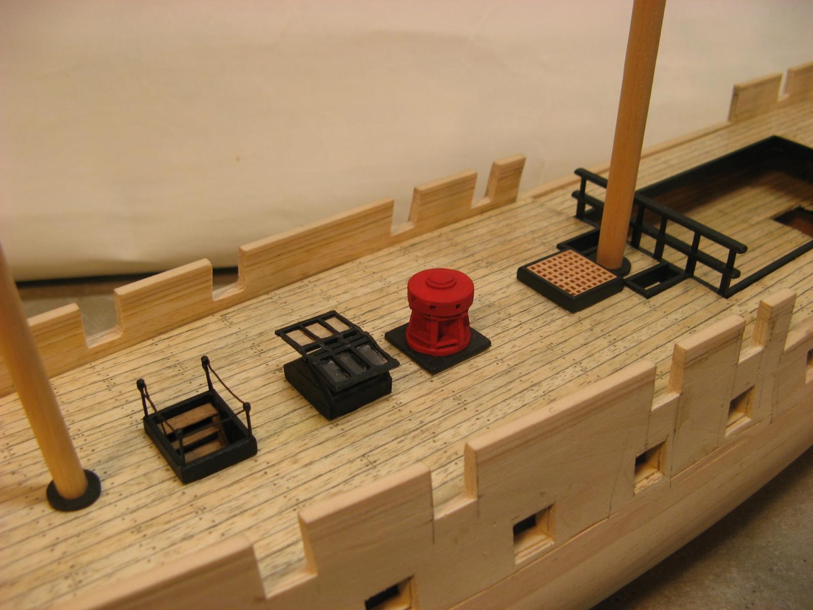
Fittings for the upper deck are being designed built and dry fitted. They need to be designed because I do not have all those wonderful detail drawings and precut bits that come with a kit so the process involves searching mainly through Lavery & Hudson and also the internet generally for pics. One of the disadvantages of this is that I am finding all sorts of different descriptions of various bits and have to decide what to follow and build.
I am also discovering interesting things about Surprise kits.
Part of my research has involved downloading a pdf copy of the Anatomy of the Ship, HMS Diana, another frigate, this time English built from the same historical period. This is quite helpful but there are significant differences to the Surprise, both in size and detail. I have noticed that one of the very popular Surprise kits bears a remarkable resemblance to Diana in some deck details. I guess that is one of the reasons that lots of research and scratch building is worth while.
So various upper deck fittings have been researched and made and look like the pics below.
A couple of items obviously missing are the ship's wheels and any of the pin racks for the belaying pins. I looked at trying to make up the wheels, one at each end of the cable drum. At 1:75 they are about 22mm diameter. This level of micro surgery is beyond me so I will be sourcing these from my friendly parts supplier. The belaying pins are similar, I haven't counted up how many I will need but there will be lots and again, they won't be very big. Again part supplier items. As I don't know the diameter or thickness I can't work out the rack hole size or what centres the holes are at. So no pin racks yet.
I have started hacking into the stern and once I have taken out the various openings there's not that much left. I made a bit of a mess of the port cable slot so I will need to rethink how to cut these out after I have reconstructed the damaged area.
The step rebates in the gun ports to fit the lids for the ports below the forecastle and quarterdeck have been made and need a bit of tidying up before painting. I am a bit confused about the gun ports in the waist area that do not have lids, I am assuming no step and the same overall outside dimensions as for those with lids. Comments would be welcome.
Cheers,
David.


-
Hi Brian,
I am about to work on the stern and have been searching to resolve the detail, particularly at the top, around the curved element.
There seem to be several interpretations starting with the diagram that you have attached to your stern frames. This looks like it is out of the Lavery & Hudson book and I have been using this as well. I have been a bit confused about what is solid and what is open.
Searching through L & H I have found these illustrations which seem to shed some light:


The bottom pic looks closer to the drawing as it includes the "hooked" cut-outs near the ends. The other pic deletes these all together.
Other kits/models have a range of layouts:
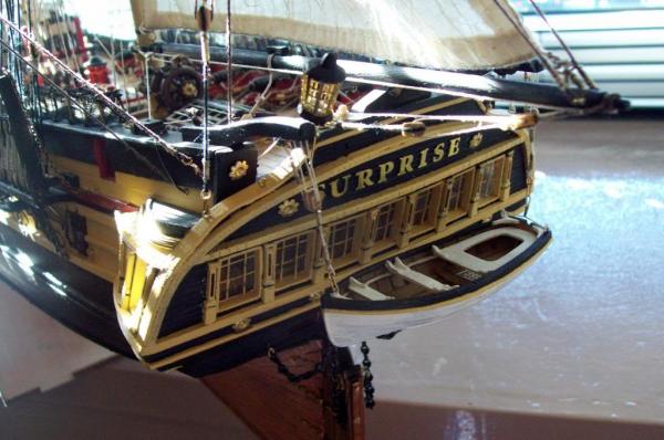
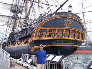
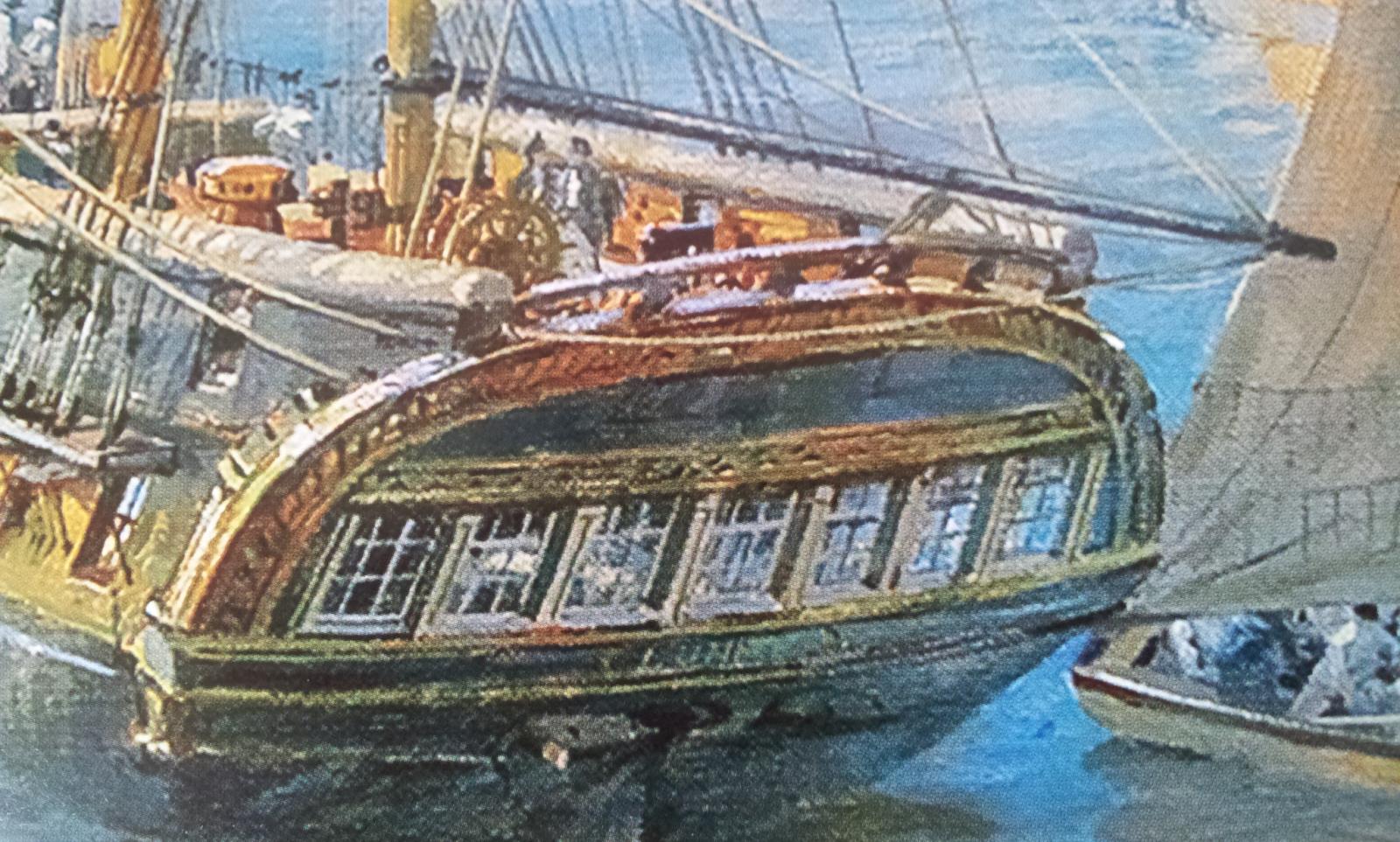
The film replica isn't really helpful although the cut-outs at the sides may be relevant.
I will be going with the lower of the 2 pics from L & H.
Cheers,
David.
- sonicmcdude, kees de mol and Waitoa
-
 3
3
-
Hi Pavel,
Your photo description of the pump construction is very timely, I need to make up 2 for my Surprise and yours are a great guide on construction.
As my pumps are hidden below the quarterdeck I may not go to the degree of detail that you have for the metal work. I really like your fabrication drawings in the background. I often do drawings as I go but they are not of the standard of yours, maybe i need to lift my game!
I am making up the fittings for the forecastle and quarterdeck and will post some pics soon.
Cheers,
David.
-
Thanks heaps Mark, your comments clarified several areas.
The L & H drawings certainly show what looks like 2 sets of gun ports on the stern, on the quarterdeck and 2 fairly shallow openings which would end up below the gun deck, in the gun room by the look of it.
I will move the 9 pdrs to the stern on the quarterdeck, I think they're too pretty to hide below.
Also the L & H hull side drawing shows gun port lids on all the gun deck ports except those in the waist. This is what I will include although I'm not too sure about the 2 piece lids shown. Elsewhere in the book one piece top hinged lids are shown and here I will take the easy way out and make mine one piece.
I did have my doubts about the 9 pdr chase guns at those forecastle ports, extreme care would have been needed not to destroy the bowsprit rig. Good to know that this is how the crew got to the heads etc.
Cheers,
David.
L & H stb side & stern views, 2 sets of stern gun ports and lids on most of the gun deck ports.
- WackoWolf and kees de mol
-
2
-
Hi Brian,
Just found your build log and had a good read.
We are heading down the same path but I seem to have about a year's head start. I suspect you will rapidly gain and then I will watch your progress as you accelerate away.
I decided on 1:75 as I didn't want the finished product to be too big for the limited storage space that I have.
Your build is looking good so far, I will watch with interest.
Cheers,
David.
-
Hi Bindi,
Thanks for the comment, it's taking time but I'm getting there. Working without the detailed instructions that you usually get with a kit means I spend a lot of time searching for information.
I have recently tried to work out mast heights. The Lavery & Hudson book has quite a bit of info but some of it is contradictory. Also, as the O'Brian books refer to Jack Aubrey's installation of a 36 gun frigate main mast this makes it even more complicated. At least the L & H book does mention that this would probably only apply to the lower section.
As you Mamoli Surprise is the same 1:75 scale as my build I would be interested in what your instructions include for mast lengths. If you can isolate the overall lengths of each section of the masts with the main lower section measured from the top deck level I would be interested to see what Mamoli includes.
Hi Mark,
Good question. I seem to have 2 more gun ports on the main gun deck than guns, not too sure what to make of it. I'm not even too sure on which deck the 9 pdr chase guns would be mounted, I have assumed the forecastle as this would give the best opportunity for firing forwards.
Another detail I am yet to come to terms with is stern gun ports, there seem to be 2 at the quarterdeck level. One of the L & H drawings shows a carronade mounted here but I doubt this as I understand these ports were for firing long guns at a chasing vessel in an attempt to bring down some spars. As the armament list I have includes only 2 x 9 pdr long guns it must have been quite a drag to move these from one end of the ship to the other if a chaser turns into a chasee.
A mystery to me is access to the heads. The L & H drawing show 2 "seats of ease" on either side but I can't see any way down or back up!
Questions, questions!
Cheers,
David.
-
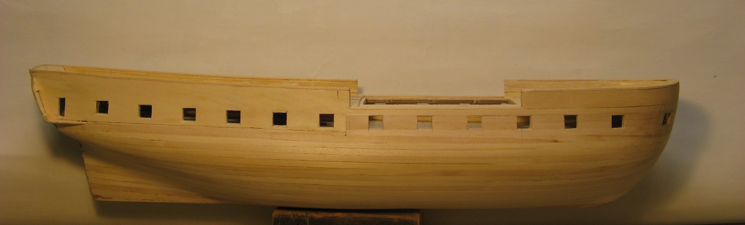
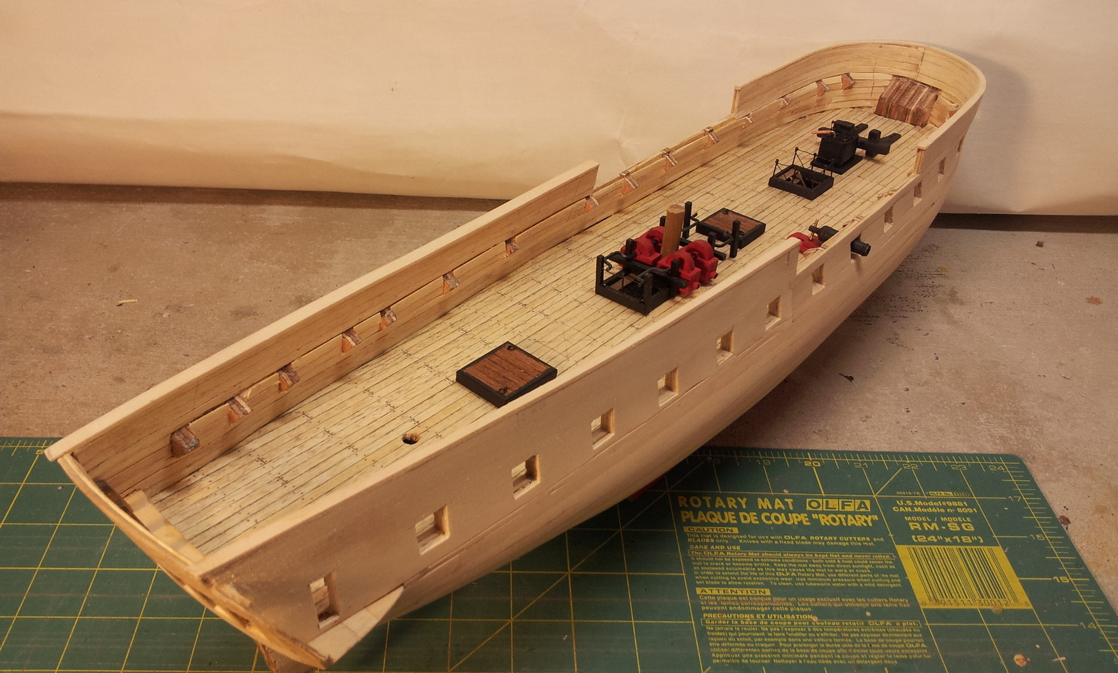
Gun ports and guns.
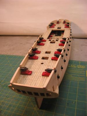
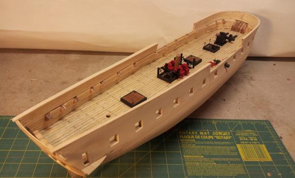
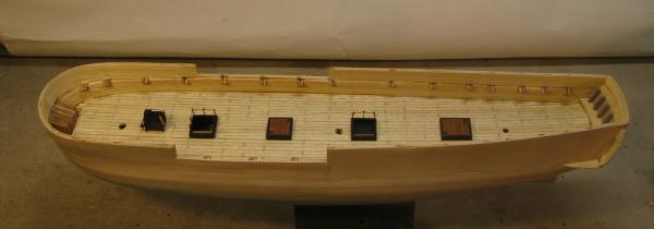
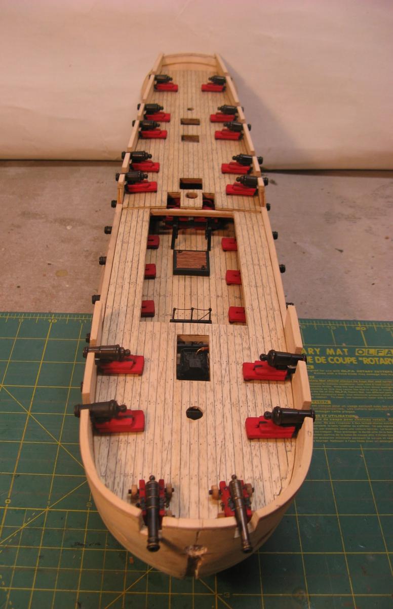
The gun ports have all been cut and to make sure that the guns are a reasonable fit all the gun carriages have been assembled and fitted to ports. When fitted the forecastle and quarterdeck guns were sitting too high in the ports. A dimension check showed that the bulwarks were not high enough so they have been raised and the gun carriages reduced in height to get a better fit. The final gun barrel angles still need a bit of adjustment but they are getting close.
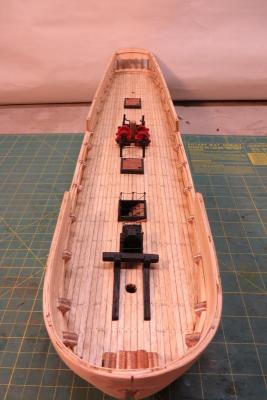
A dry fit of all the bits assembled to date gives a good progress pic.
The capstan is the only major part missing from the upper deck and all the forecastle and quarterdeck fitting are next to be made.
I think that I am close to being able to start the top planking on the hull. Should be fun.
Cheers,
David.


- Mirabell61, Bindy, canoe21 and 5 others
-
8
-
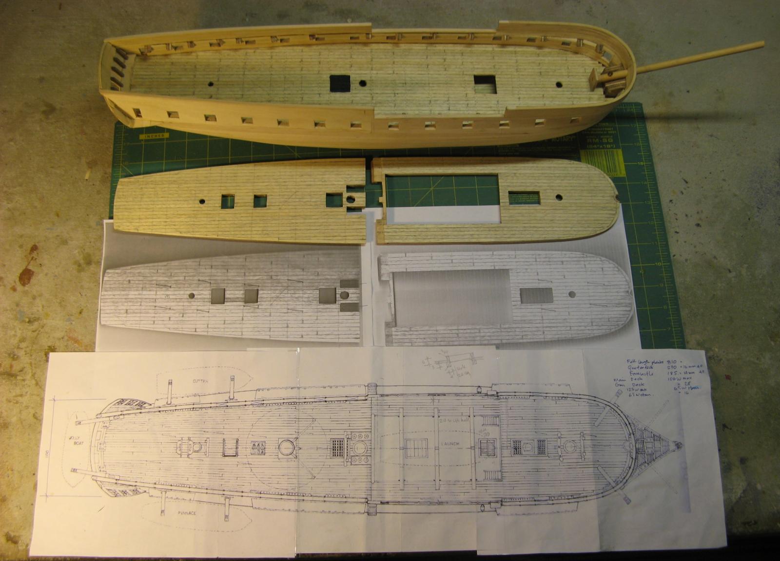
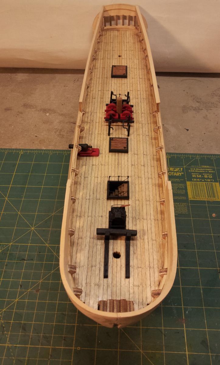
Top deck planking.
Planking to the forecastle, gangways and quarterdeck has been laid. An OK result, the planks, at 4mm, are a bit wider than I would have preferred but this is what my friendly supplier had. I fit the planks in full lengths then score the plank end joints later once I have worked out the underlying beam positions. The first job is to set up the joint locations so the offset pattern works and all the planks are a reasonable length. I find the easiest way is to photocopy the decks then I am free to scribble all over them. It took about 4 or 5 attempts to arrive at a reasonable layout.
Now to mark the plank end joints and create the treenails.
Cheers,
David.

Hull with top decks removed, photocopy of deck with plank end joints marked and the scanned and enlarged deck drawing from Lavery & Hunt.
-
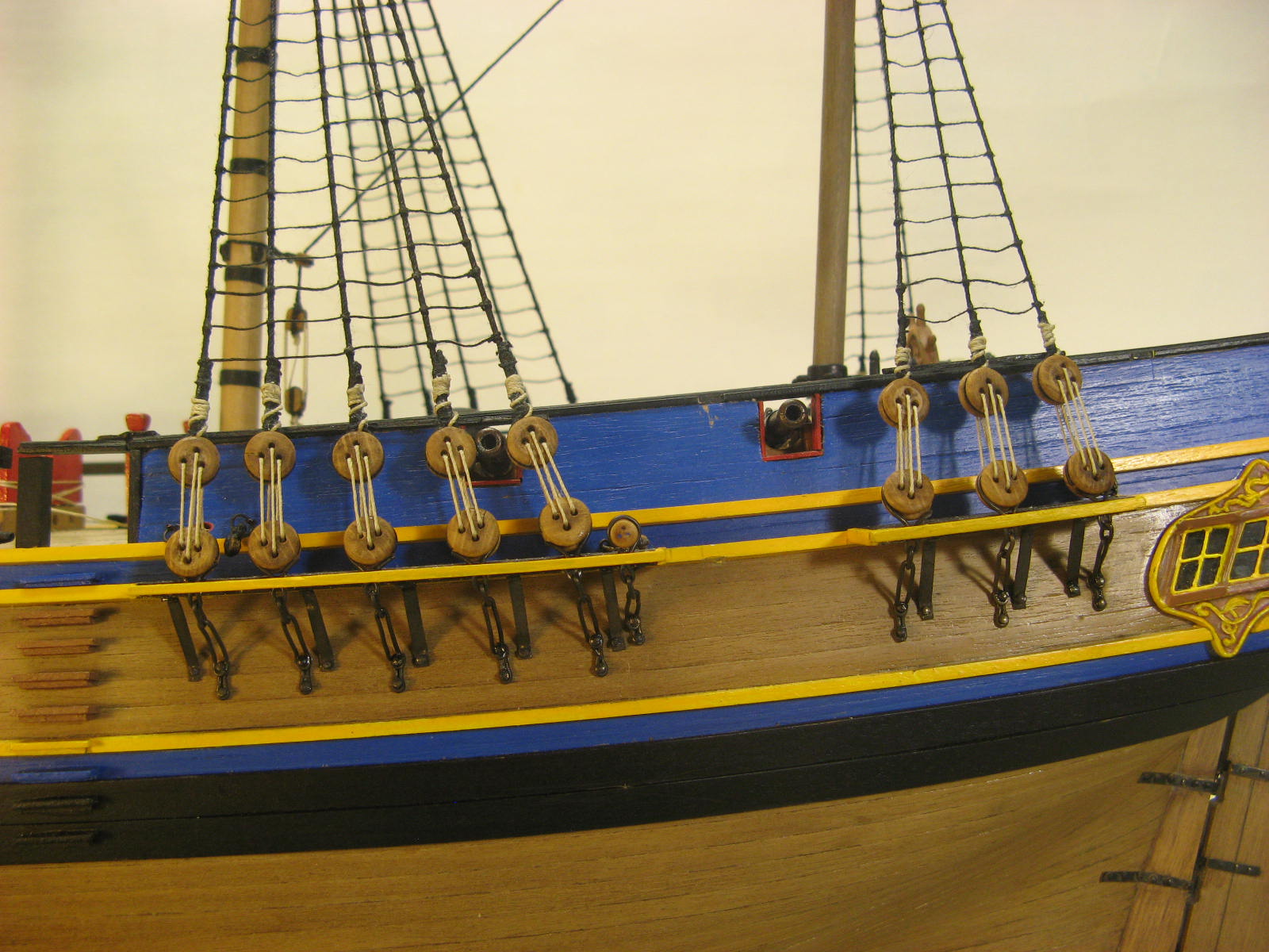
About making up chains that are joined and not see the join. I encountered this when making up the chains for Bounty. The kit items were far too short so I had to start from scratch. (it looks to me that the kit parts you have are a bit on the short side). I started with brass wire, about 0.5mm thick and bent up the parts of the chains. I contemplated trying to solder or join them in some way but decided that the joint would be too obvious, particularly when I used brass black to colour the brass. So I made the joints right at the bottom or at the back where they wouldn't be seen and didn't put too much tension on them when doing the rigging of the shrouds. It worked out OK.
While you are busy relocating the chains to miss the gun ports (such is the learning process) and making the chains longer (probably worth the effort) a detail that often gets overlooked in my experience is the alignment of the chains and shrouds.The complete assembly right down to the bottom attachment to the hull should be in the line of the shrouds as they run down from the mast. This includes the top part with the deadeye that runs through the channels at an angle to keep this alignment. I spent quite a bit of time working on this on the Bounty and the result looks OK.
I also decided to do the ratlines progressively, the idea of doing them all in one go was truly terrifying! And the Surprise probably has 2 or 3 times the number of ratlines as the Bounty.
Rigging is quite an experience and attention to the small details makes all the difference.
It took me a year to rig Bounty.
Hope this helps.
Your overall build looks great.
Cheers,
David.

- billocrates, mtaylor and GuntherMT
-
3
-
Hi,
Just found your log and had a browse. It's really nice to look through a log that doesn't have pages of chat, I'm very glad that the site co-ordinators decided to focus on building rather than chat.
I am also building the Surprise and after assessing the available kits, decided to go for a scratch build using the Lavery and Hunt book.
I will follow your build, I'm sure I can learn lots. A big disadvantage with scratch building is the lack of all the detail drawings.
Looking at progress on your log you look like you are about to run the shrouds. If they are going to be positioned as shown in your pics you may have some conflicts with the chains and gun ports. L & H shows the shrouds in groups to avoid the gun ports on both decks.
I have cut the gun ports for the main gun deck and am about to cut them for the upper deck. Before I do so I am going to run false shrouds to ensure I miss the gun ports.
Cheers,
David.

Side view from L & H showing grouped shrouds.
-
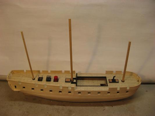
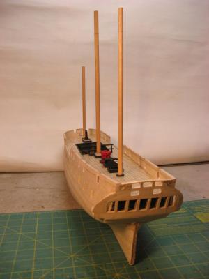
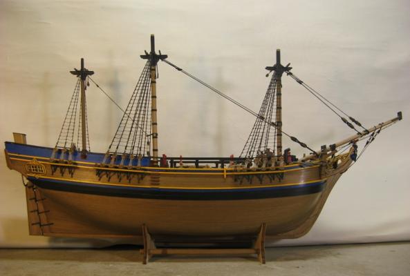
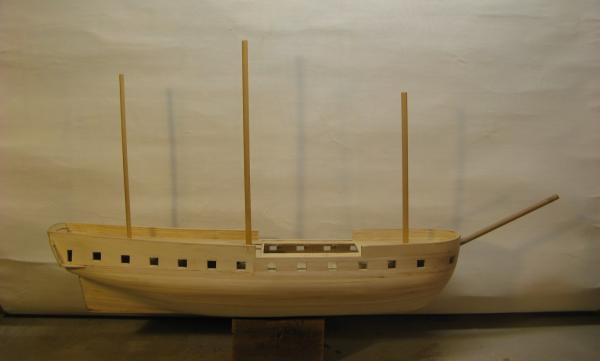
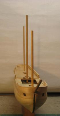
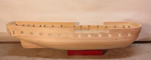
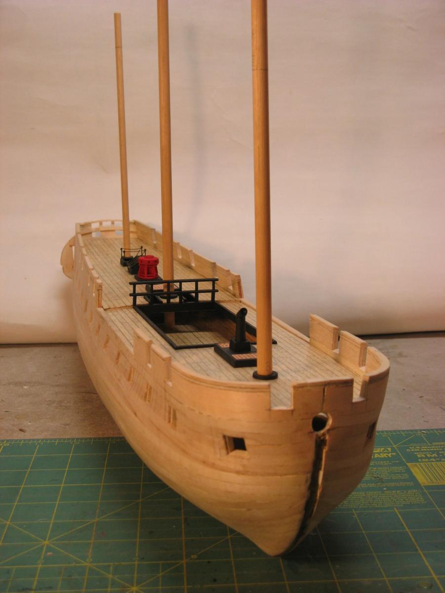
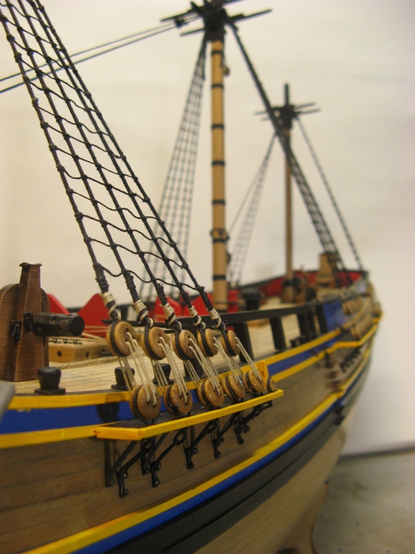
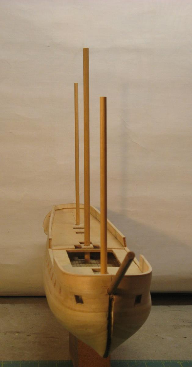
A bit of a milestone, starting to look like a ship.
As described before I needed to fit the lower mast sections to be able to locate the shrouds so the upper deck gun ports can be positioned. I also found that I needed to fit the bowsprit as it cuts into the forecastle deck and affects the planking layout.
All now fitted.
The mast rake is a bit of a mystery, it seems to me that individual captains could adjust the rake as the sailing properties of a ship developed and the rake would be changed to improve performance. About all that I'm pretty sure about is that the masts were only ever located vertical or raked back, not raked forward. So I have decided on a modest rake as would probably befit a ship at the beginning of a commission. The foremast is raked back about 1 deg, the main about 1.5 deg and the mizzen about 2 deg. The masts fitted into the pre-made holes in the upper deck and passed through the holes inn the forecastle and quarterdeck with minor adjustments and ended up vertical.
Cheers,
David.
-
The fabrication of the guns has been done, now for some more work on the hull.
Before I cut the upper gun ports the forecastle and quarterdeck need to be planked so I can get the height of the ports correct in relation to the height of the gun barrels on the carriages. Also, I will need to make up the lower mast sections and the channels so I can position the lower shrouds to make sure that the location of the upper gun ports is correct in relation to the standing rigging. Not a good look to have gun firing lines through the rig.
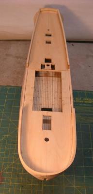
All the holes for the hatches etc on the upper deck have been cut ready for the planking.
After I had cut the main gun deck gun ports I realised that the tops of the ports were too close to the gunwale line and there was not enough space to neatly fit the channels so I have raised both the gunwale at the waist and the bulwarks at the bow and stern.
I have cut out the false beams that spanned the waist as they were originally installed to support the deck during the initial hull construction and were in the wrong position for the final beams. According to the drawings from Lavery & Hunt these beams look like they are removable as they are positioned above the gangway and supported on brackets,
Cheers,
David.

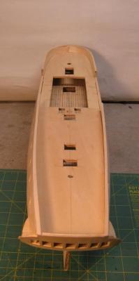
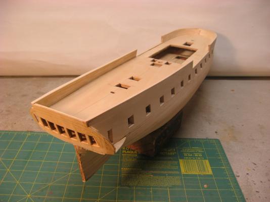
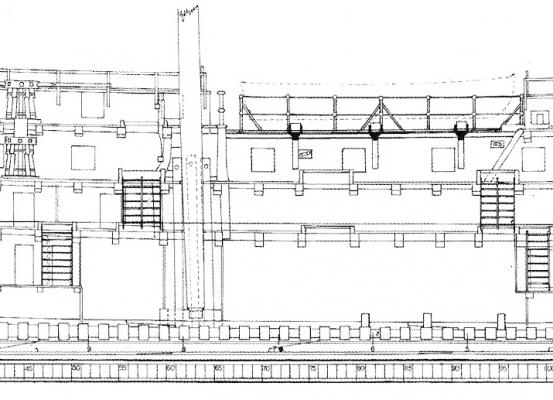
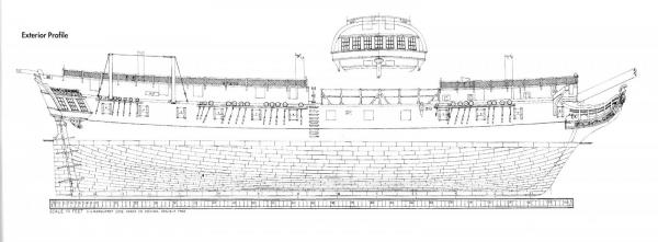
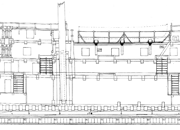
Hull section showing beams over the waist above the deck line
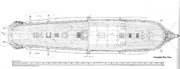
Hull plan showing the beams positioned on the gangway planking
This plan shows the distinctive frigate hull shape to maximise the usable area of the gun decks, broad bow
and relatively wide stern compared to other ship types.
- Waitoa, popeye the sailor, mtaylor and 5 others
-
8
-
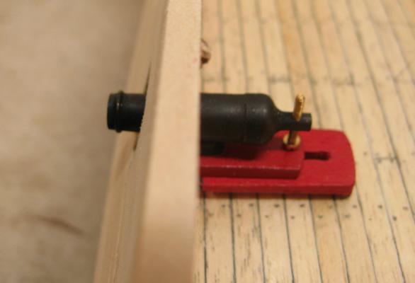
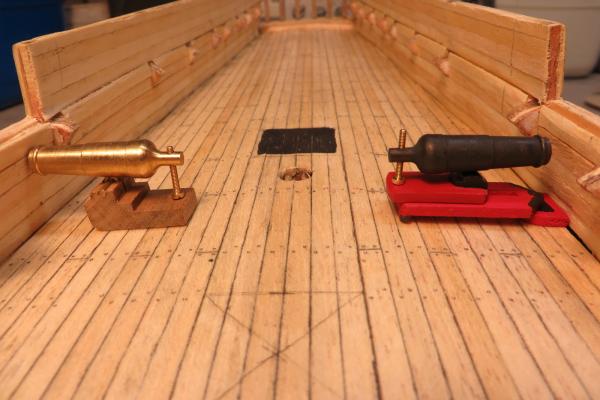
Long guns and gun tackle generally.
Along with the carronades the Surprise was equipped with 2 x 9 pdr long guns as chasers.
I purchased these as gun kits complete with carriages and some metal work. The kits are not a bad start to achieving an OK finished product. I split the the parallel sided carriage down the centre and removed some material to achieve the angling inward at the muzzle end of the sides, changed the brass rod axles for larger diameter dowels and added some different metal work.
Some paint and a reasonable finished product.
Now for the second one, at least there are only 2!
Interesting to note that, although the 2 kits come from the same manufacturer and carry the same part number, the barrels are significantly different. Once positioned on opposite sides of the deck I don't think this will be noticeable.
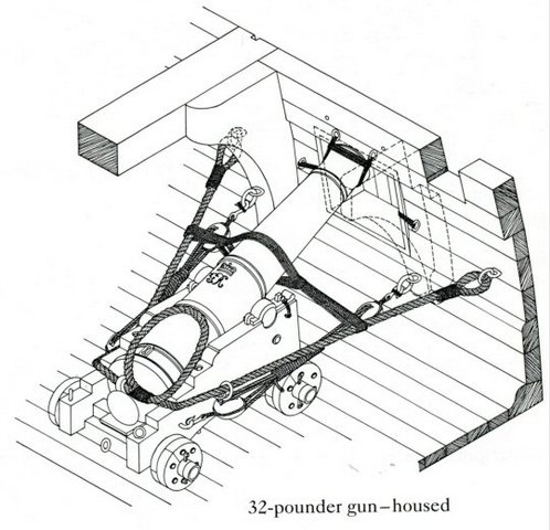
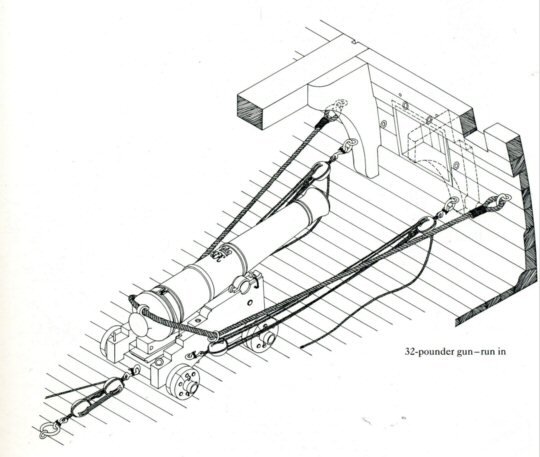
I have been doing some research into the gun tackle for both the carronades and the long guns. There are certainly some different views out there!
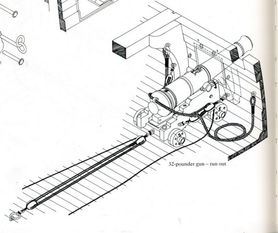
One thing that I have not really understood was if the tackle used to haul the guns out to their firing position was disconnected from the carriage when the gun was fired and the breech rope controlled the recoil and then the tackle was rehooked for the next out-haul, or if the tackle was left attached and played a part in controlling the recoil process by the ropes running out through the blocks. During the online searching I found a thread about the Victory that described the gun operation and stated that the tackle was left attached and played a part in the recoil control. The diagrams that accompany this article also very clearly show the tackle arrangement for a long gun. Clearly shown is an item of tackle that is often missed in gun detailing, the in-haul tackle, used for hauling the gun inboard if needed and also to hold the gun in position when the roll of the ship may want to send the barrel back out the port during the reload process. Very useful. I will definitely be using this info when time comes to detail the tackle for the Surprise long guns.
Carronade tackle is a bit more of a challenge. Pics of the USS Constitution were very informative. These carronades differ in detail to those that I have for the surprise but the tackle must be pretty similar, 2 out-hauls and an in-haul for the slide and 2 side-hauls for the wheeled carriage. A breech rope for the recoil. 6 bits, that's a lot of tackle for each gun! 24 on the upper deck and 14 on the quarterdeck and forecastle. 190 block and tackles. Good grief.
Cheers,
David.
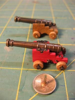
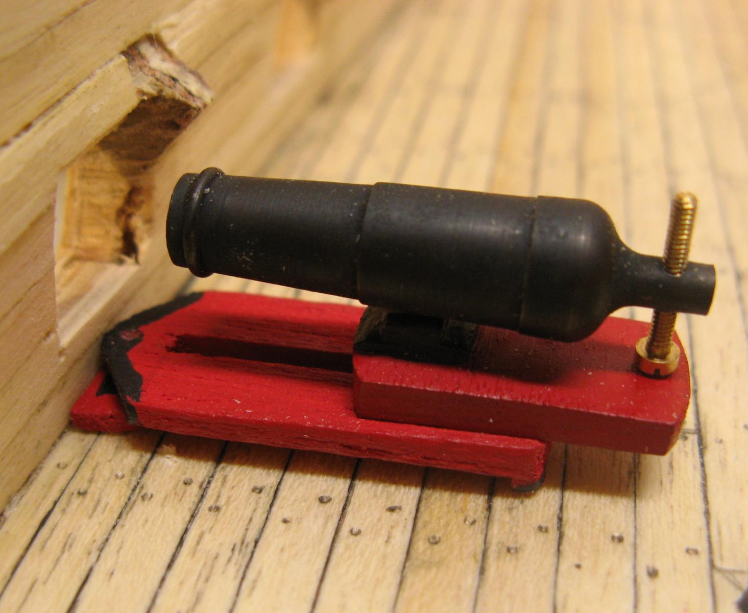
Surprise 9 pdr long guns, kit item and as modified

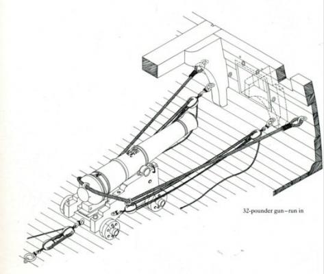
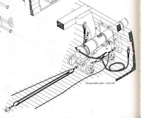
Diagrams from Victory book
USS Constitution carronade tackle, in haul not in place
-
Nailing tool!
Sounds like an interesting idea, I don't use many nails in fact.
Not sure how this got onto my build log.
Cheers,
David.
-
Hi Captain71,
Welcome to the Surprise build group.
I started my Surprise about a year ago. Initially I thought I would go for a kit build and the Mamoli version was one option, at 1:75 the finished product is a manageable size. Other options at 1:48 or so would have ended up pretty large.
In the end I decided to scratch build using the Lavery & Hunt book as the basis as it includes a version of the original plans.
The hull is going well and I am working on the fittings for the upper deck. (This is actually below the quarterdeck and forecastle). Working out how to fully detail this upper deck was a bit of a challenge as all the detail has to be in place before I install the top deck sections and I didn't want to end up doing dusty work with all the guns etc. in place. So I have got removable deck sections that I can complete remotely. So far so good.
Cheers.
-
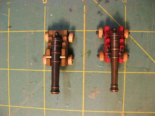
Gun assemblies.
My version of Surprise, based on the Master & Commander books, carried 24 x 32 pdr carronades on the main deck and 14 x 18 pdrs on the forecastle and quarterdeck as the main armament with a couple of 9 pdr chase long guns. At this stage, I'm not sure where the 9 pdrs live, there seem to be a couple of spare gun ports on both the upper deck, the forecastle and at the stern, maybe they were moved around as needed. Possibly it's up to me to decide where to put them.
The carpentry shop has been in full production with carriages for both carronade sizes being produced.
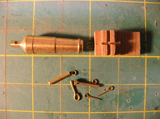
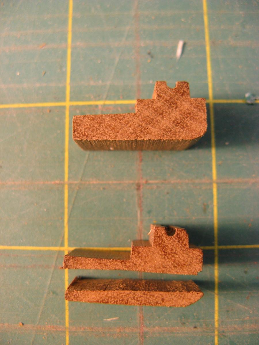
Kit for 32 pdr carronades. The kit carriage forms the basis for the slide in the final assembly.
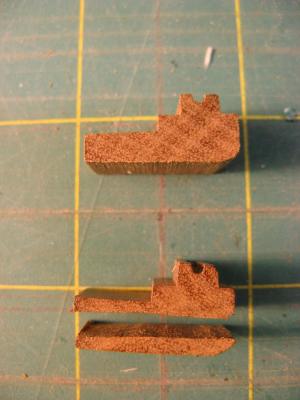
Trickiest part of making up the slide, slicing the carriage longways to reduce the height. (Yellow lines = 25mm grid)
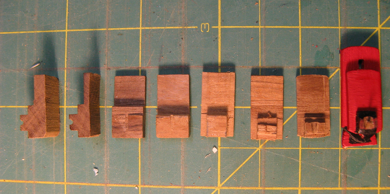
Steps involved in changing from the kit carriage to the finished slide. The lower part of the carriage is fabricated from balsa and ply.
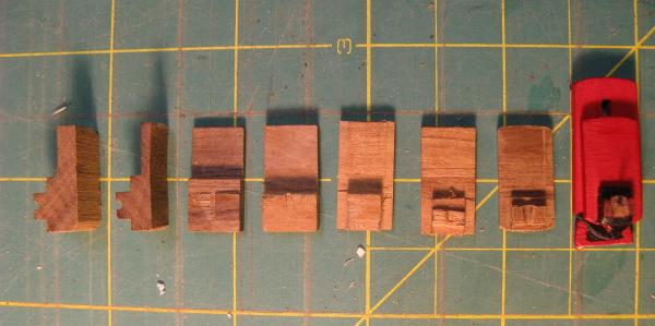
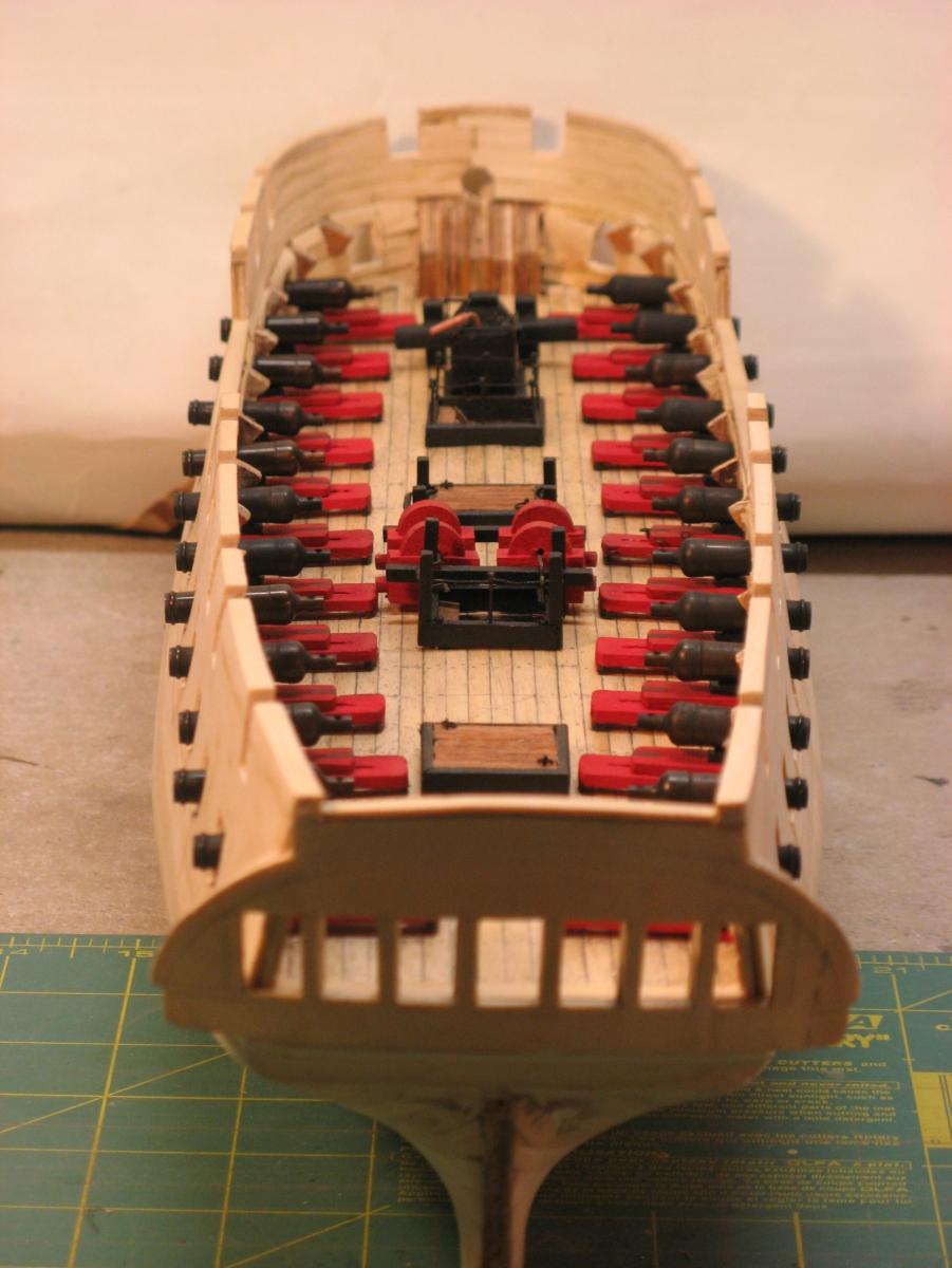
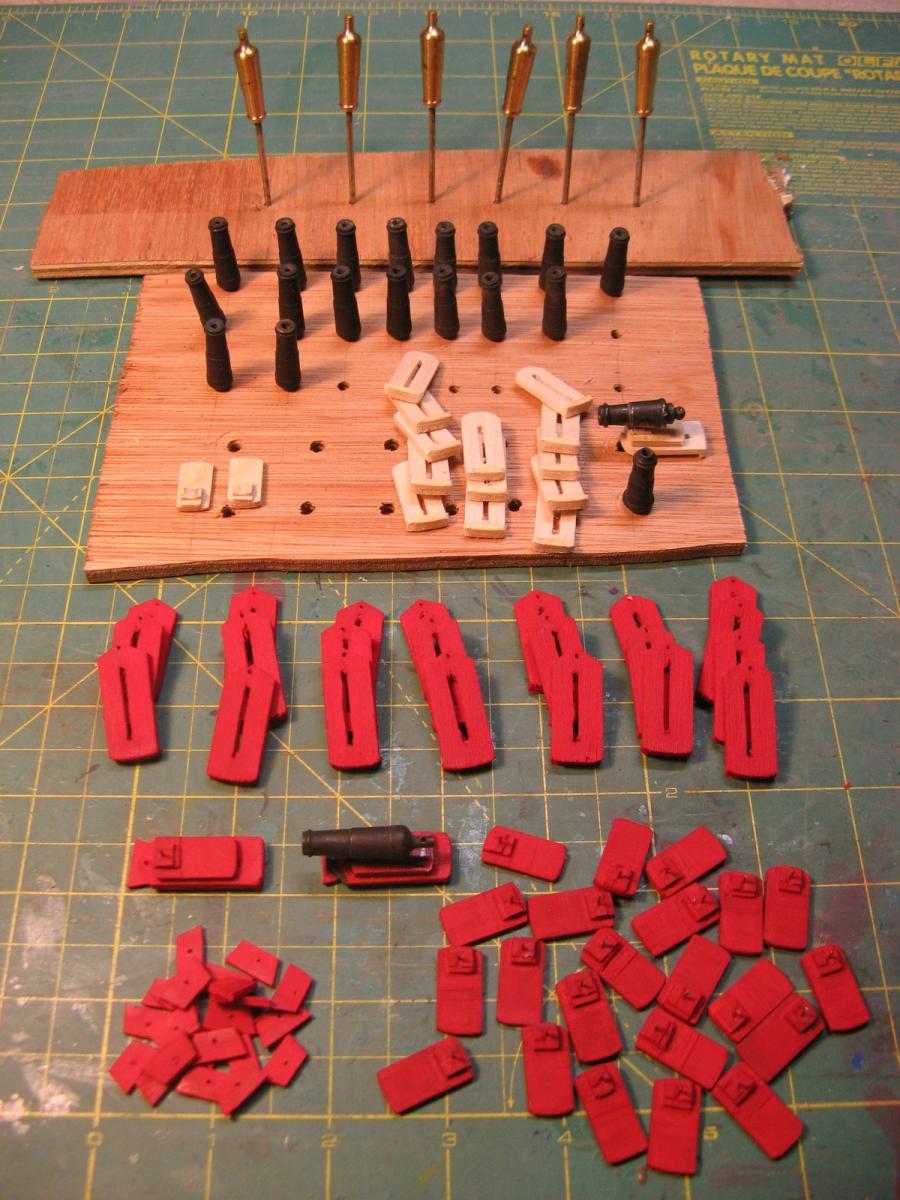
Progress so far.
All 32 pdr components have been shaped and painted, detail painting still to come. 18 pdr carriages partly shaped.
Most of the 32 pdr barrels have been blackened and colouring of the 18 pdr barrels has started.
- Angarfather, gjdale, mtaylor and 7 others
-
10
-
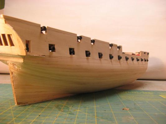
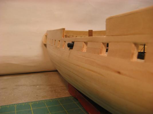
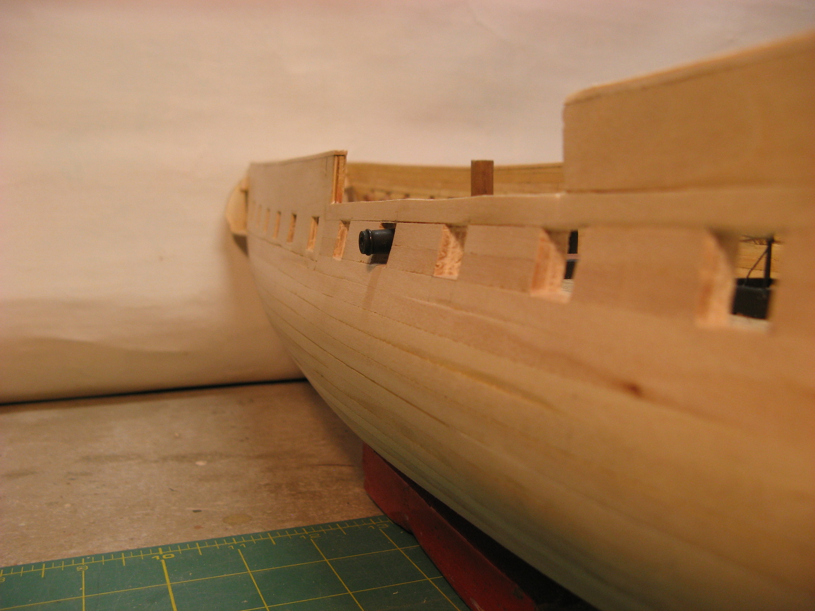
The gun ports and the doorway into the quarter gallery have been cut into the starboard side, no major difficulties although one of the ports ended up a little high and needed a bit of filler at the top. I am glad I decided to cut now rather than after the final planking is in place.
Now for the port side.
The quarterdeck and forecastle ports will be set out and cut once I have planked these top deck sections, made up a gun carriage for the 18 pdr carronades and checked the position of the ports.
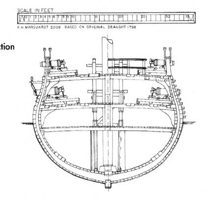
The gun barrel and carriage size, port positions and the hull thickness has worked out pretty close to the hull cross section in Lavery and Hunt.
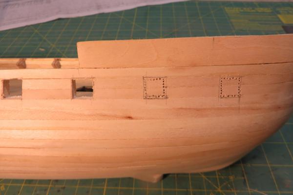


Lavery & Hunt cross section
- popeye the sailor, canoe21, egkb and 5 others
-
8
-
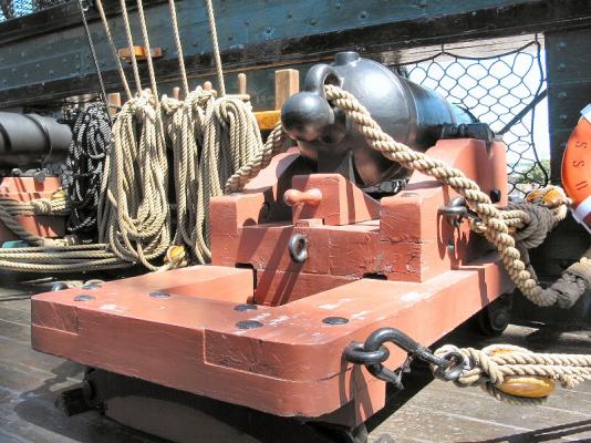
More deck fittings. The most important fittings on the upper deck are the guns, my build will carry 24 32 pdr carronades on this deck.
After searching, I found that Mantua make a 30mm carronade kit that is pretty close to the 1:75 32 pdr so I have acquired 24 of these. I have also acquired 14 smaller 18 pdr carronades and 2 long 9 pdr guns for the quarterdeck and forecastle.
I was originally going to leave cutting out the gun ports until I had completed the outer hull planking and cut through all the thicknesses in one go but I have decided to cut them out before I do the final outer hull planking to give a bit more of a margin for error, something will surely go wrong somewhere. Without the outer planking in place I think I have a better chance of doing any repairs in a reasonable way.
To confirm the precise position of the gun ports, particularly vertically, I wanted to have a sample gun assembly made up to be sure that the gun fittings would look OK and that the gun barrel would end up in the centre of the gun port when the gun was horizontal.
The Mantua gun kit included a timber carriage as well as the brass barrel and some brass fittings. The timber carriage is all wrong for a carronade so I have made up my own using the drawings in the L & H book. At least the Mantua carriage was OK to cut down for the slide. I have yet to add the metal fittings for the gun tackle. The tackle looks even more complex than for a normal long gun as both the main carriage and the slide seem to have side tackle as well as the gun having the usual breech rope and "back-haul" tackle.
As with the brass swivel guns on the Bounty I have used brass blacking fluid that I got from a gun shop. A very light oil rub after the blacking has done its job brings up quite a good finish.
Mantua gun kit left, my version right.
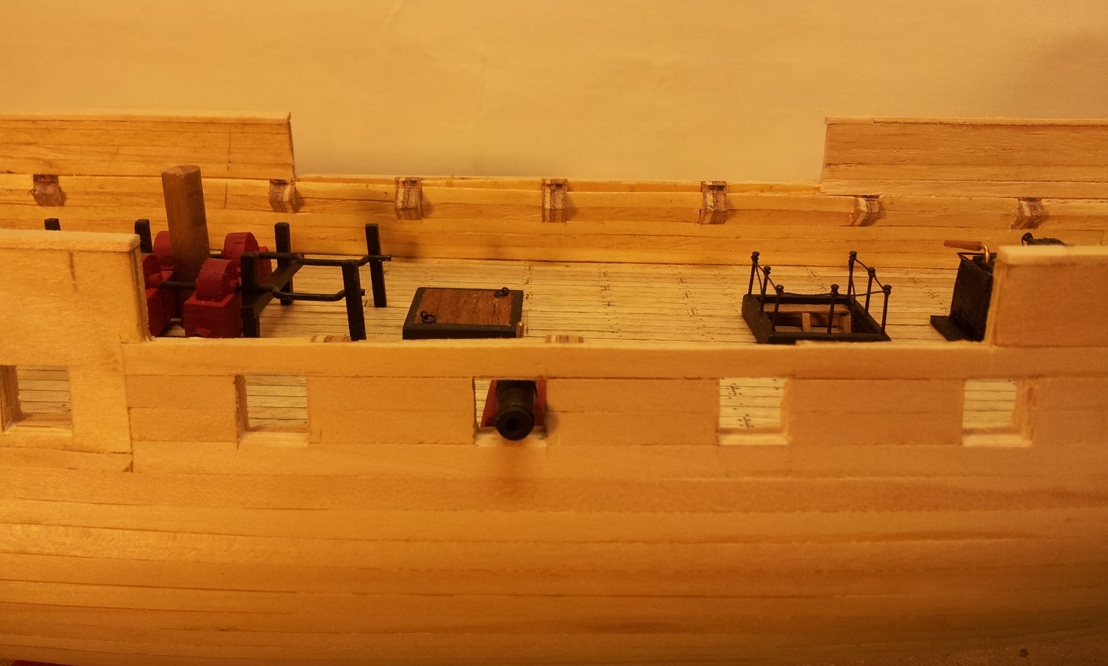
-
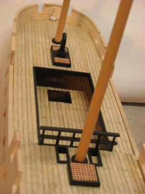
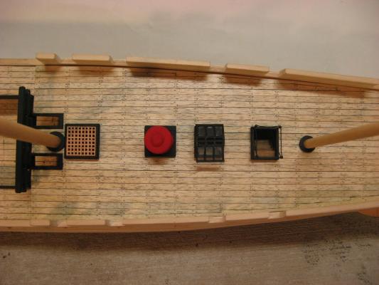
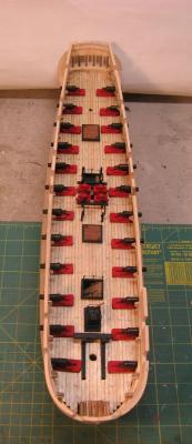
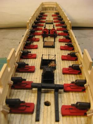
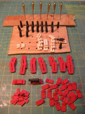
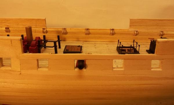
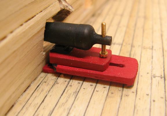
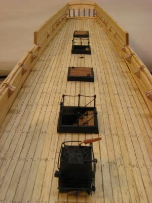
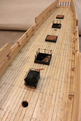
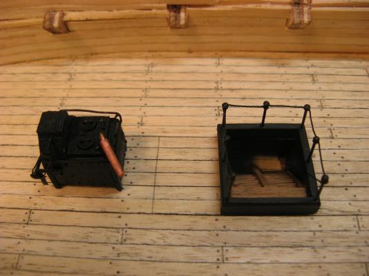
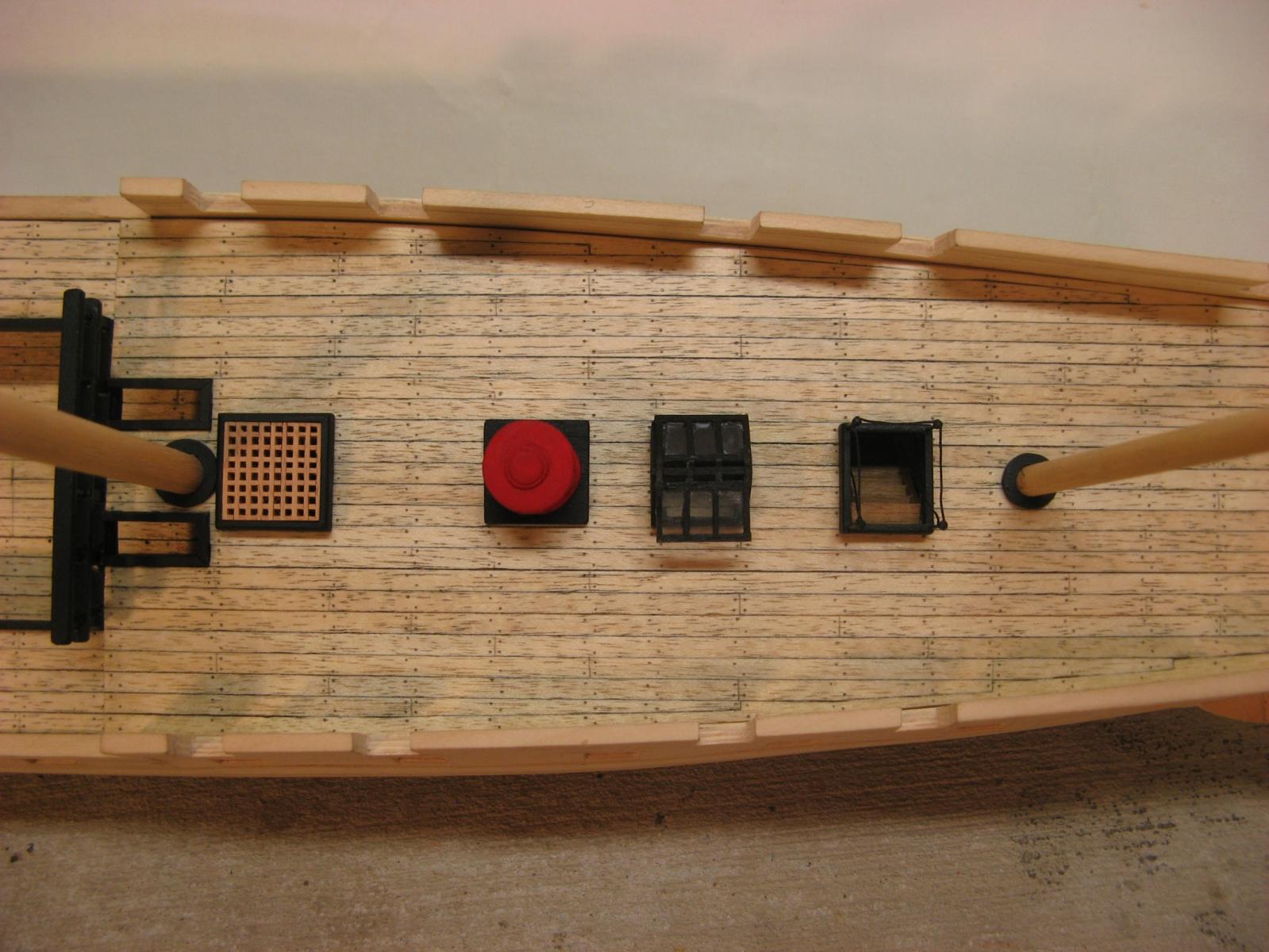
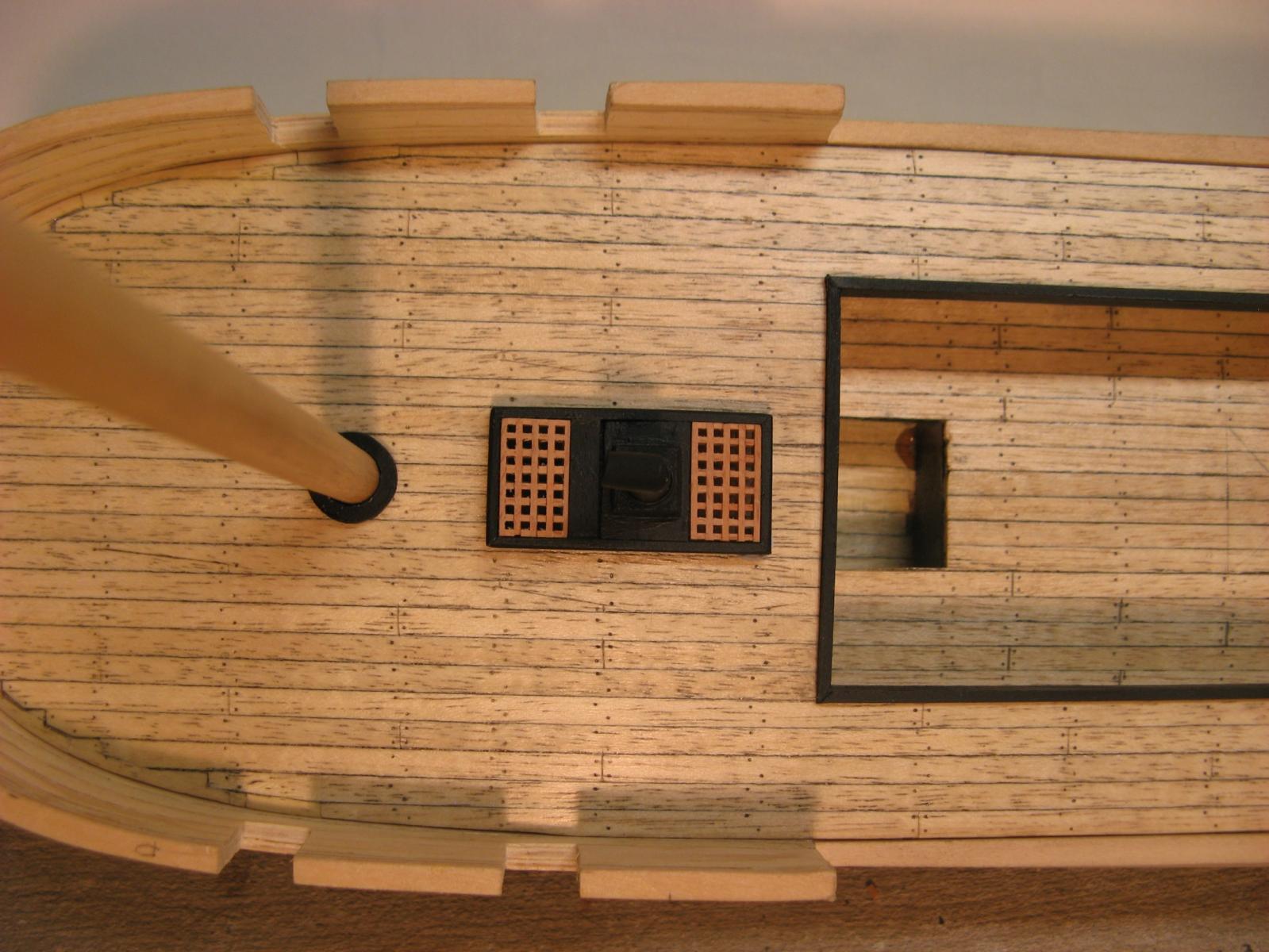
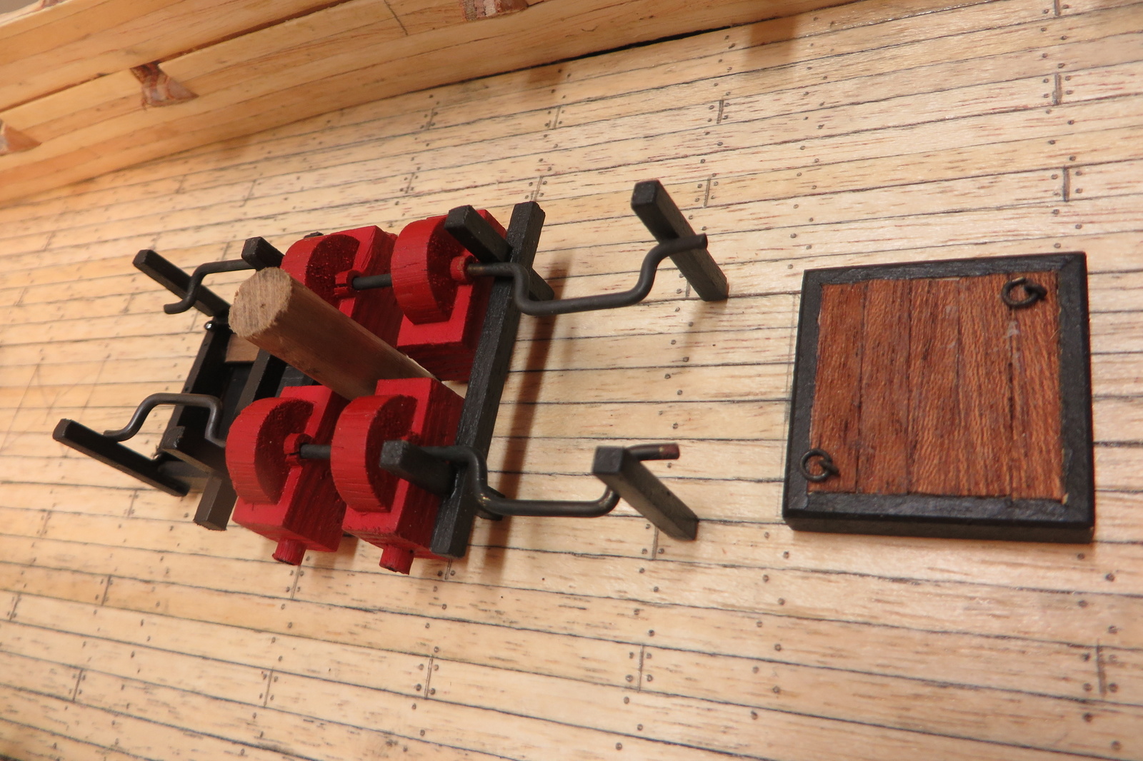
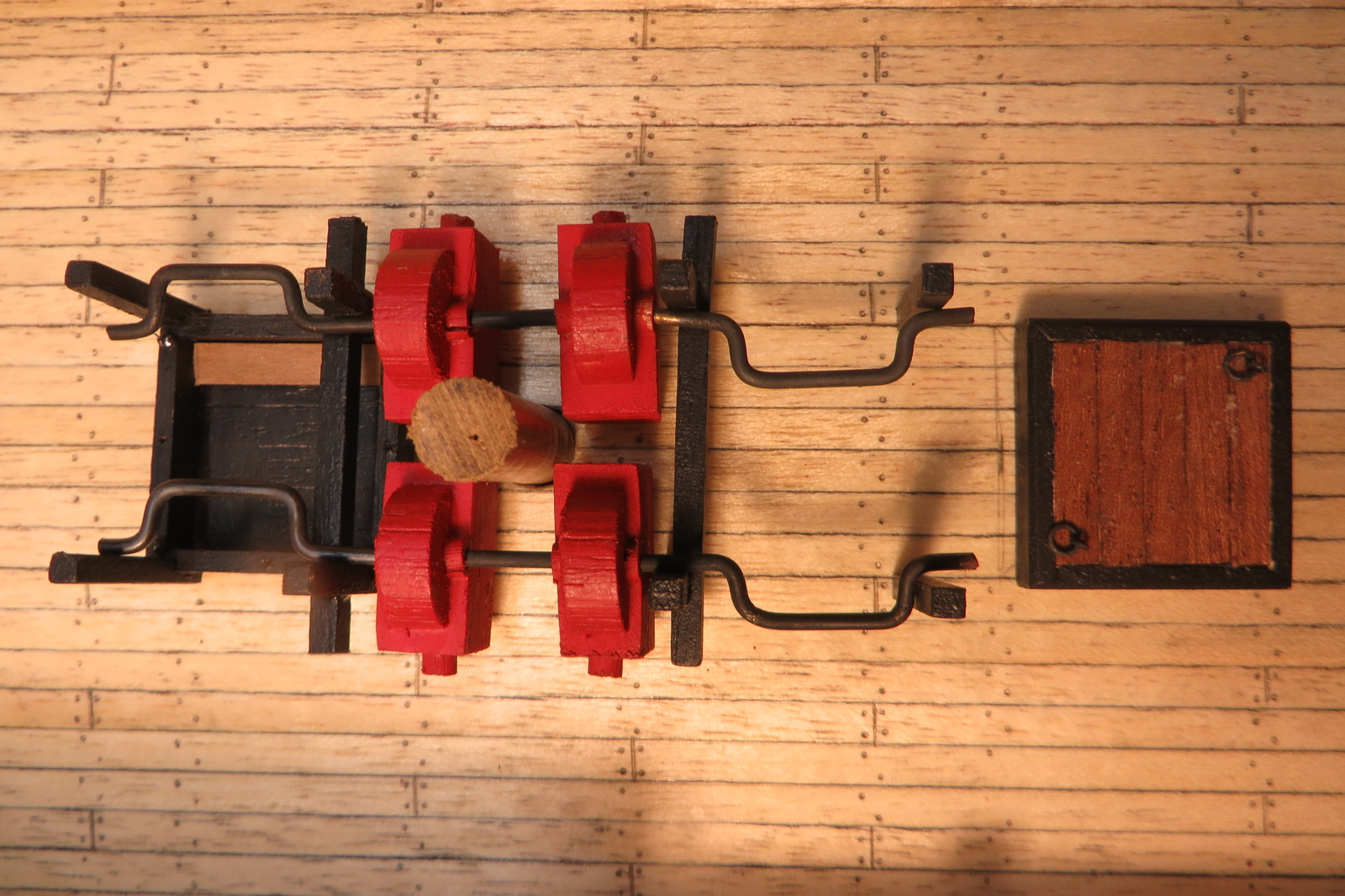
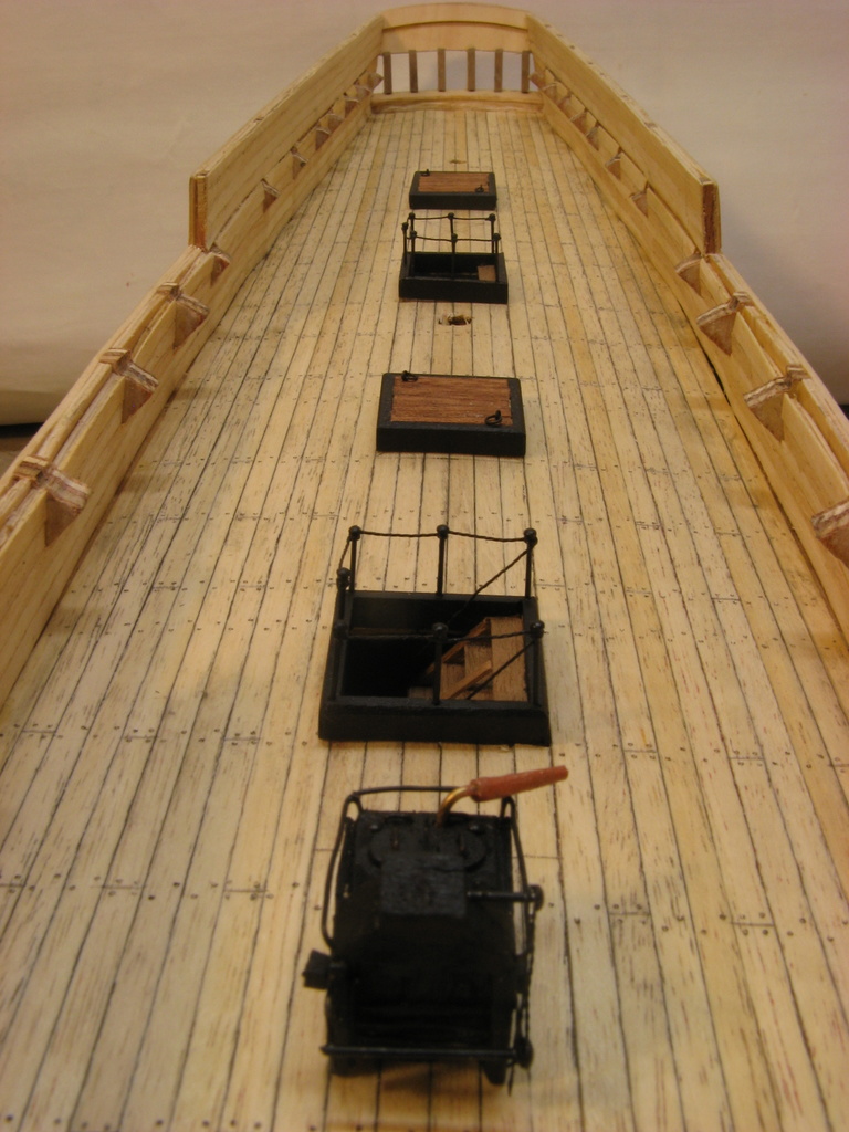
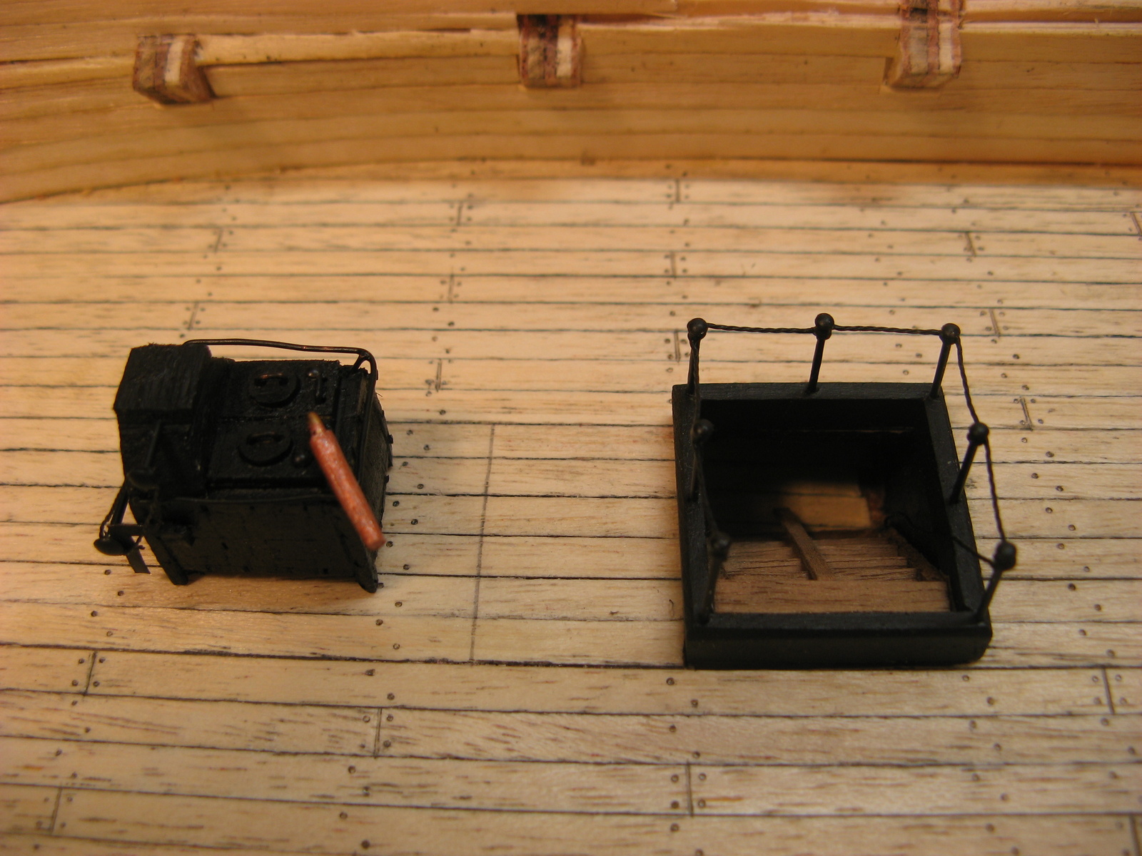
Some more deck fittings. The riding bits and chain pumps have been fabricated and dry fitted. The modified scroll saw base was very helpful in cutting the small parts. Final details such as fixings for the handles are yet to be added.
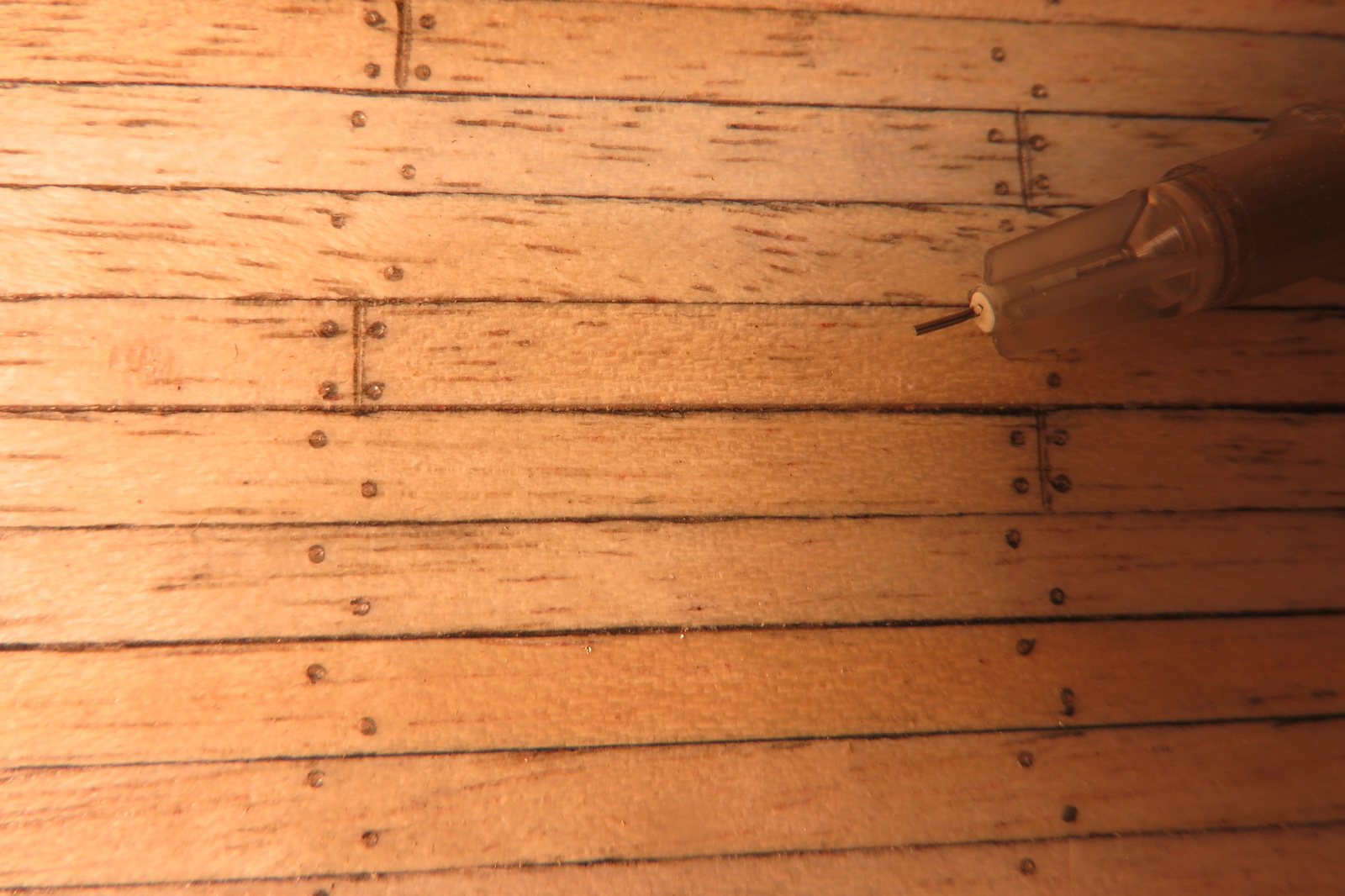
The pattern of the deck treenails has been completed. I decided to try a technique I spotted on another build log, a medical syringe needle cut down to form appropriate sized circles. I visited the local pharmacy and, after a bit of explaining and a look of bemusement on the pharmacist's face walked out with some 0.4mm needles. This was the smallest size that comes as a separate part and not with the syringe attached. At 1:75 scale this is 30mm, close enough to treenail size. I carefully cut the point off and added a dowel handle and set to work. I was pleasantly surprised that this process didn't tak a huge amount of time. I used a template that I had made up when I built the Bounty. After making the circles with the needle I spun the tip of an HB pencil in the depression.
Riding bits and chain pumps added

Chain pumps
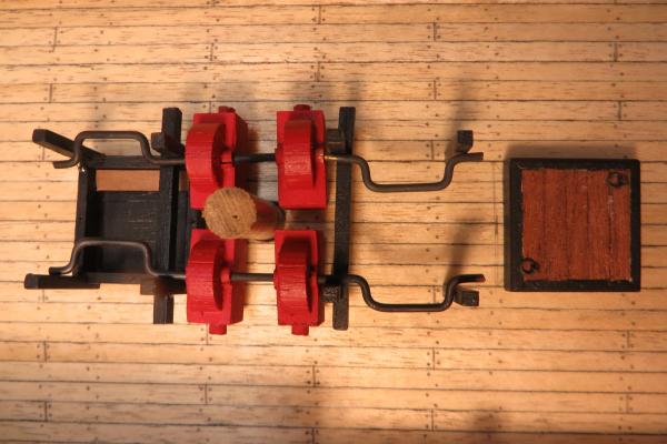
Chain pumps
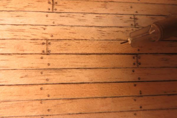
Treenails with needle tool
-
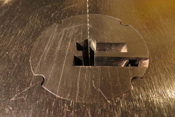
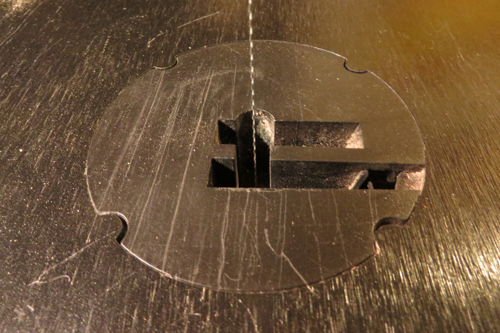
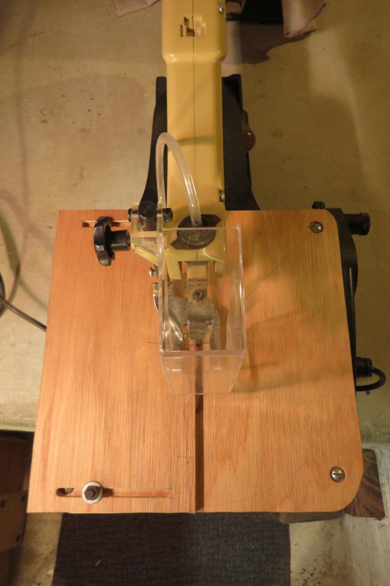
I have needed to do some fairly detailed wood cutting and tried the scroll saw but found the hole in the base plate too big, small bits disappeared! Also, I had difficulty controlling small sections of timber, they tended to jump around.
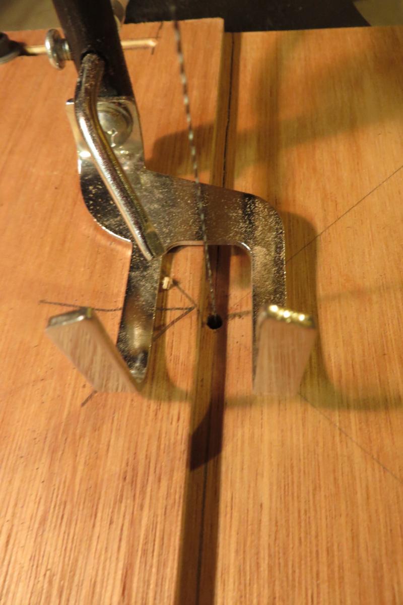
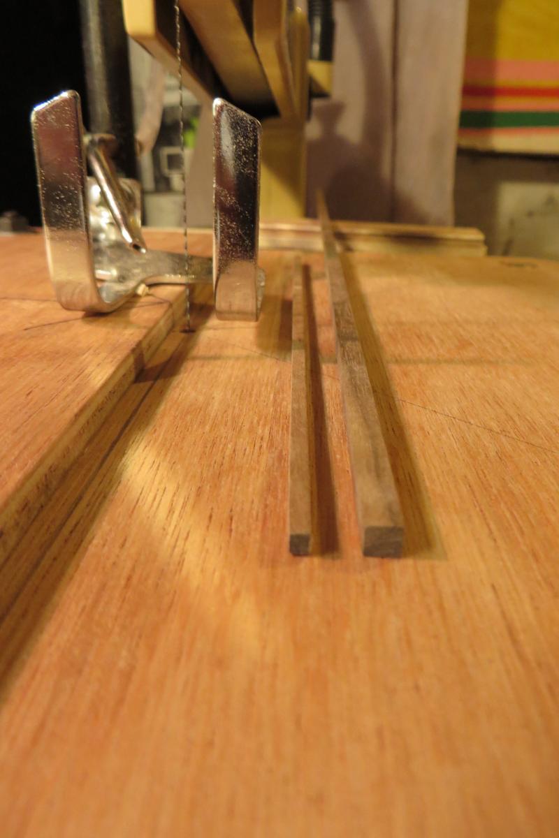
The solution was to make up a new ply base plate with a minimal hole where the blade passes through. At the same time I made up a pretty basic fence for controlling the width of cuts. I reduced some 4x4 mm walnut to about 2.5x2.5 mm for parts of the chain pump frames, it worked fine.
Cheers.
Base plate allowing for angle cutting

New 6mm ply base plate and fence

Minimal hole for the blade

4x4mm walnut reduced to 2.5x2.5
-
Hi,
My first 2 builds were kits, the Port Jackson Schooner which I built pretty much with what came in the box, followed by the Amati 1:60 Bounty which started off with what came in the box but after acquisition of McKay's Anatomy of the Ship book involved lots of scratch built details to increase the accuracy. The PJ Schooner was a 1 year effort, the Bounty 3 years.
For my next and current build, HMS Surprise, I decided to go for scratch build, at least for the hull and the woodwork. The metal fittings I will buy as I don't have the resources to make these up.
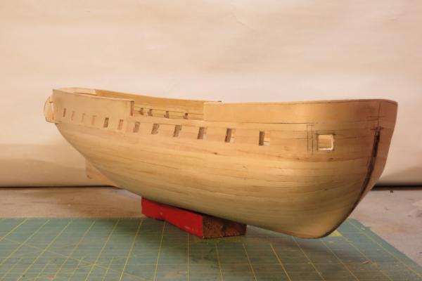
For me one of the most interesting aspects of the hull scratch build is researching to find original drawings which I could use, rather than acquiring a set of model plans prepared by someone else which would be their interpretation of the original drawings. I was given the Lavery & Hunt book which includes a set of ship's plans based on the Admiralty drawings, not drawings developed for model construction. It was then up to me to interpret these and develop a method of making up the hull as close to these drawings as I could. Plan preparation involved lots of scanning, scale changing and pre-planning to achieve as close as I could get to a true hull shape. One thing I wanted to achieve was a lightness of construction at the stern. Most kits seem to include a mass of woodwork to make the stern detail where the real ships are quite lightly built in this area, the stern was often the "Achilles heel" of these ships. I also wanted to achieve a "see through" look where the entire upper deck could be seen through the stern windows as if the ship was in "cleared for action" mode with the internal partitions removed.
So far so good and I am reasonably pleased with progress.
It is interesting to compare the hull shape that I have ended up with to the hull shape of a Mamoli kit that I was considering buying to use as a base for a serious kit bash. The Mamoli kit is much "pointier" at the bow and narrower at the stern and quite a different length to width proportion. I think that Mamoli must have a sort of generic hull design that they adapt to different models. Frigates like the Surprise were quite narrow for their length and the stern is comparatively wide, presumably to accommodate guns for the maximum length. These proportions would have made them fast through the water but they would have been hell in a cross sea!
Cheers,
David.
-
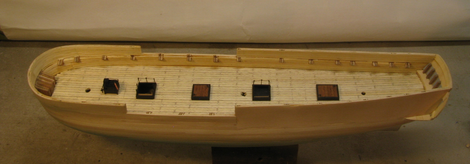
Update time.
I have been on holiday in the centre of Queensland, great place, the true wide open spaces.
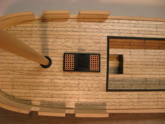
Since returning home I have been working on fitting out the hull interior including internal planking, plank end joints and fixings and fittings. The plank end joints and fixing locations are based on a deck beam diagram included in the L & H book. The fittings for the upper deck (below the forecastle and quarterdeck) done so far are the galley, companionways and hatch covers.
I need to do a bit more research to work out what the pumps etc look like before I make them up.
Cheers,
David.
-
The gun port reveals are the total thickness of the hull from the outside face of the planking to the inner face of the inner lining planks that is exposed when the gun port covers are open.
You can see from the drawing that the hull is slightly thinner at the top of the reveals than at the bottom but there are limits to the detail accuracy that I am willing to go to and my gun port reveals will be the same depth at the top as at the bottom. They will be thinner at the upper deck than at the main gun deck so at least that relationship will be accurate.
The drawing also shows the "knees" that form part of the lateral stiffening of the hull structure. I am not too sure what to do about these. My ribs have haunches where the upper deck beams rest and these look a bit like the "knees" but they are not really big enough. A problem I have with the "knees" is that I don't know how many of them there are. I haven't yet found a drawing showing where they are placed lengthwise in the hull. On my model they won't be visible except through the open gun ports or through the stern windows so maybe I can get by without going to too much detail in this area.
Cheers.
-
Hi Marktime,
Thickening of the hull is needed to bring the model up to the scale thickness of the real ship so that the gun port and other penetration reveals will be close to correct as I will have all the gun ports open and guns run out.
The bulwarks are significantly thinner than the hull at the main gun deck level. This hull does not appear to have a substantial wale line and has a single slight thickening at the line of the main deck and a rail line at the upper deck. My under planking does not have this thickening which I will create in the final planking.
My model hull thicknesses are based on this L & H cross section.
Cheers,
David.
- archjofo and Elmer Cornish
-
2


HMS Surprise by Navis Factorem - FINISHED - 1:75
in - Build logs for subjects built 1751 - 1800
Posted
Hi Brian,
Thanks for the feedback, it's taking some time but I am gradually getting there.
The research has been long and arduous. A couple of sources I have found have been very helpful with those missing details.
The Jotika build log that covers the construction of the prototype for their Surprise kit has lots of pics and can be found here:
www.jotika-ltd.com/Pages/1024768/Surprise_Front.htm
Some of the details are better than others, I found the pump construction and some of the deck details helpful, I think the bow and stern details leave a lot to be desired.
Another helpful resource is the Anatomy of the Ship book for HMS Diana found here:
http://www.libramar.net/news/anatomy_of_the_ship_series/1-0-43
If you scroll down through the book titles you will find Diana and clicking on the words "THE FRIGATE DIANA" opens up a download page. It took a while to download but I ended up with a pdf file of the complete book which I loaded onto my tablet and use as a reference while building.
This site has lots of links and I think it was one of my best research finds.
Although the Diana is an English built frigate rather than French built as for Surprise she is of the same era and I think that the English refit of the Surprise would have included standard English details so I have used some of the bits from here also. The Brody stove details came from here.
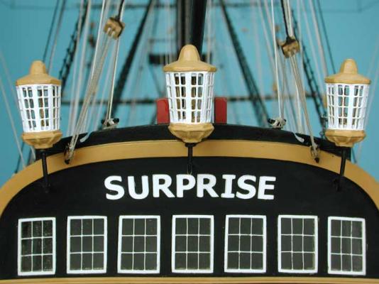
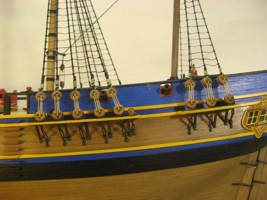
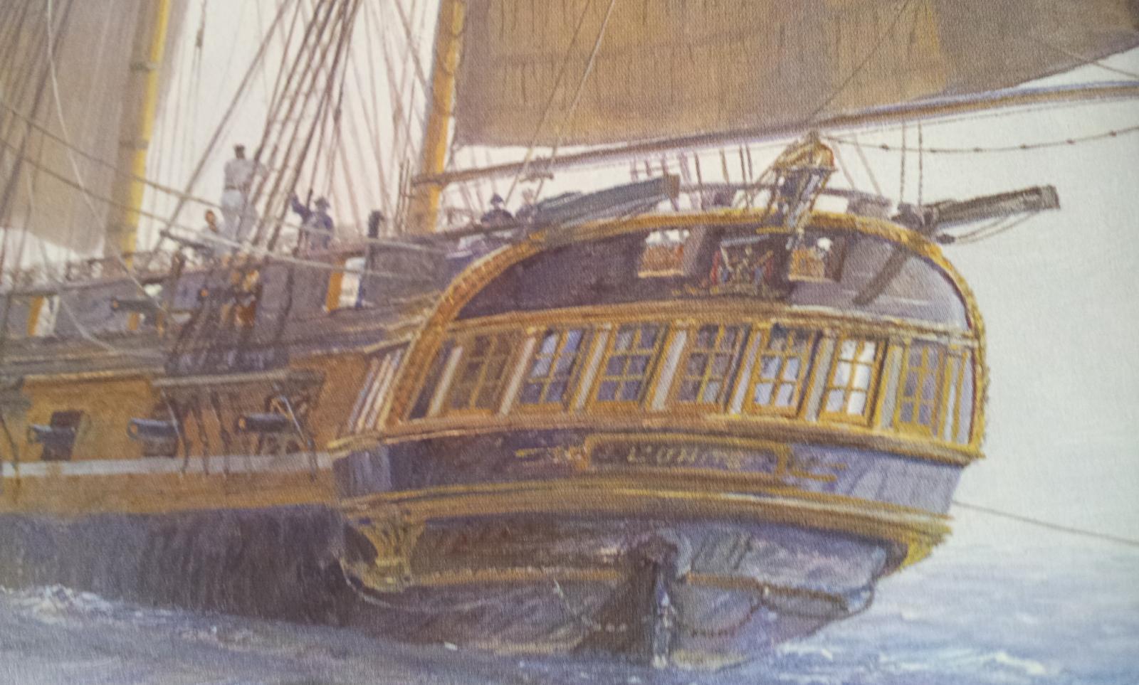
I have started some serious painting of the interior of the hull and the model is being transformed somewhat. As for the real Surprise there won't be much natural timber visible at the end of the build. Pretty much everything above the water line will be painted with the hull exterior being the classic yellow/black Nelson checker. In some ways the frigates worked a bit like stealth fighters. They would use their comparatively small size and bulk with lots of black paint on the hull and masts/spars to evade and creep up on victims, particularly in poor weather or at night.
I have pondered long and hard about the hull below the water line. The ship would have been coppered but I am yet to be convinced of this look. I haven't seen many ship models where the copper bottom looks OK. My thinking at the moment is to clad the entire hull in a plank veneer of a reddish brown timber, paint the topsides and leave below the water line natural. I'll see how it looks.
Hope this helps.
Cheers,
David.