bigjimslade
-
Posts
8 -
Joined
-
Last visited
Recent Profile Visitors

-
 mtaylor reacted to a post in a topic:
Offset for Hull Thickness
mtaylor reacted to a post in a topic:
Offset for Hull Thickness
-
Offset for Hull Thickness
bigjimslade replied to bigjimslade's topic in CAD and 3D Modelling/Drafting Plans with Software
Actually, I was planning to just post the files to help people out. But I don't want to post one that will bring the wrath of the internet down on me. 😞 -
mtaylor reacted to a post in a topic:
Offset for Hull Thickness
-
Offset for Hull Thickness
bigjimslade replied to bigjimslade's topic in CAD and 3D Modelling/Drafting Plans with Software
Would you know of any sources that can mill a solid hull? I was not able to find any source that could cut the shape. I was told I need a four or five axis milling machine. I could only find people with 3 axes. Plank of bulkhead is my third approach. -
mtaylor reacted to a post in a topic:
Offset for Hull Thickness
-
mtaylor reacted to a post in a topic:
Offset for Hull Thickness
-
mtaylor reacted to a post in a topic:
Offset for Hull Thickness
-
mtaylor reacted to a post in a topic:
Offset for Hull Thickness
-
Offset for Hull Thickness
bigjimslade replied to bigjimslade's topic in CAD and 3D Modelling/Drafting Plans with Software
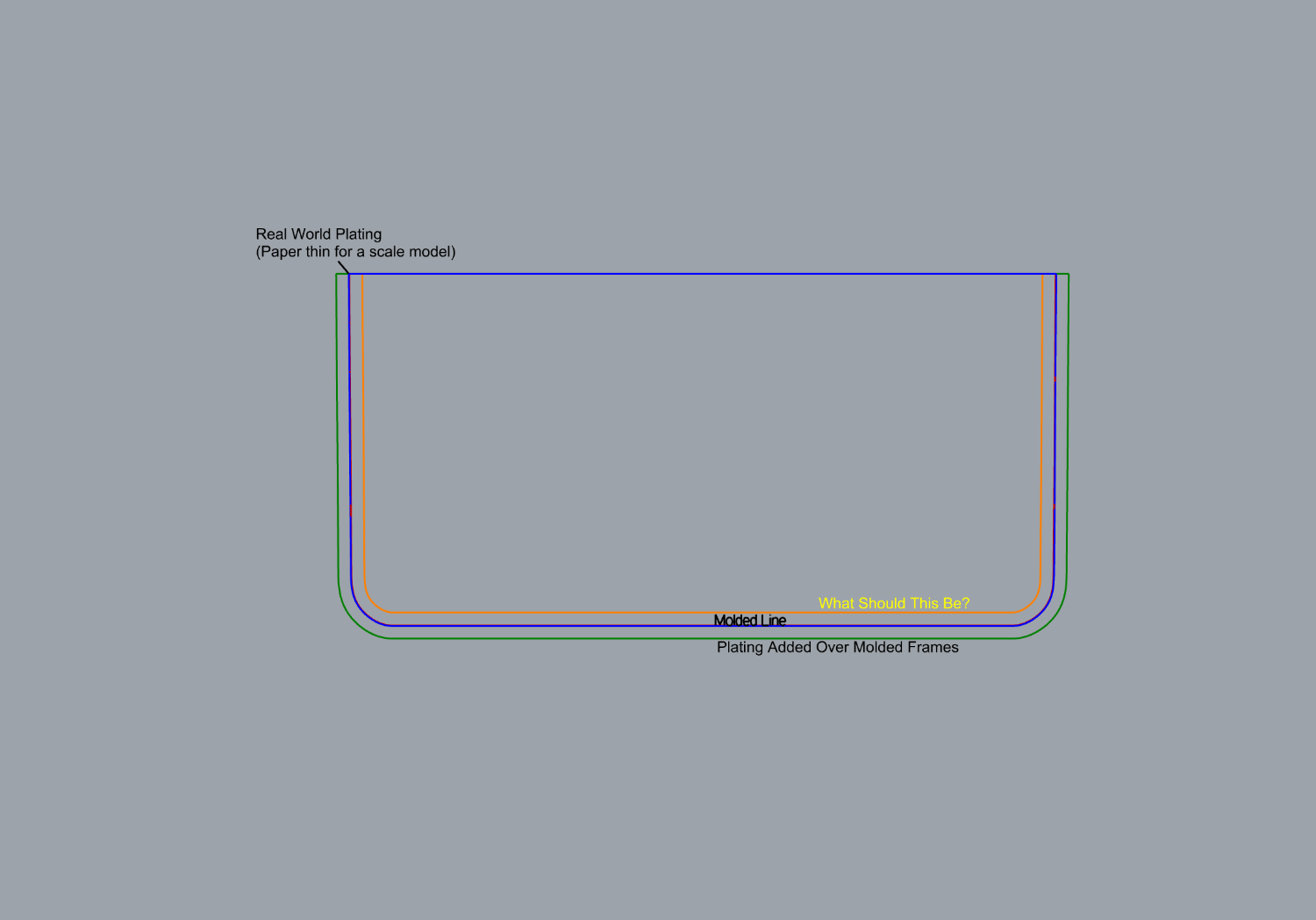
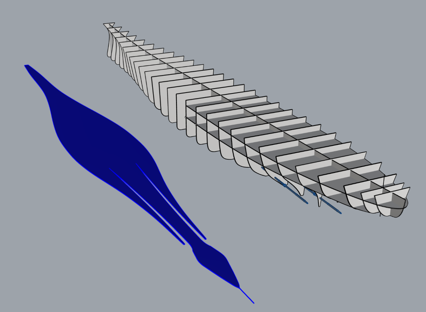
Let me try this again. Here I have a molded cross section in RED. 1" "real world" plating in scale is in Blue. In 1:192 real world plating is a paper thin 0.005 inches. For someone to build something like this they would have to use something thicker. Here I have arbitrarily picked 1/8" (in blue). That much shell over the model lines visibly distorts the hull shape because it add a scale 4 feet to the beam. Therefore. I need to offset the frames to allow for a shell thickness that sufficiently thick for a scale model (which would be something like green). Because I lack experience I have no idea how thick that needs to be for a 4 1/2 foot long model. So much do I need to reduce the frames to allow adequate thickness for the shell of a scale model?
-
Offset for Hull Thickness
bigjimslade replied to bigjimslade's topic in CAD and 3D Modelling/Drafting Plans with Software
Miscommunication here. I just want to get a smooth hull at the molded lines. "Real world" plating in scale would be way too thin for a scale model. I am trying to figure out what would be a realistic shell thickness for such a hull so that I can subtract that from the frames. If I leave the frames at scale and someone has to add 1/8" of material to make a strong enough shell, the shape is going to look way off. -
Offset for Hull Thickness
bigjimslade replied to bigjimslade's topic in CAD and 3D Modelling/Drafting Plans with Software
Thanks, I have the shell sight edges edges table and table of offsets. Got those into Excel, then into Rhino to create a 3D model of the plating locations. I did the same to get the hull form. I have played around with an offset of 0.04-inches to get an idea of what could be down but I am thinking that might be too thin. I made all this stuff (except for the test frames) for structural analysis. People keep asking me for laser cut frame patterns without giving any direction beyond that as to how thick the shell would be. I have seen some really ugly models where the frames did not account for the shell thickness.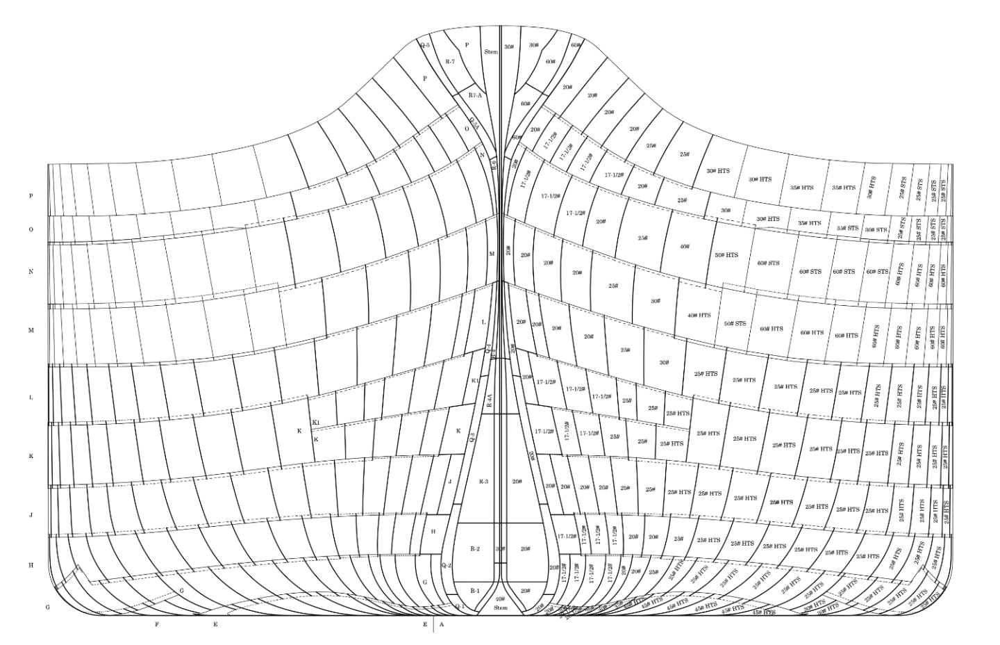

-
Offset for Hull Thickness
bigjimslade replied to bigjimslade's topic in CAD and 3D Modelling/Drafting Plans with Software
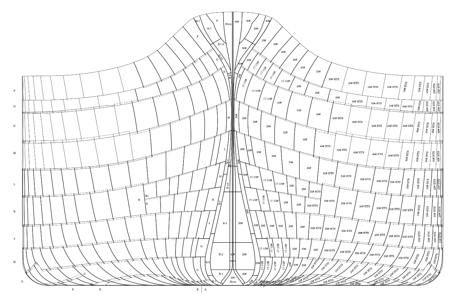
More clarification: The relationship of the plating to the molded lines varies widely by location. In places whether the strakes alternate the molded line is sometimes on the outer face of the inner strakes and inner face of the outer strakes. In most cases the inner faces of the inner strakes it at the molded line. In places where the each strake laps the one able, the plates zig-zag at the molded line. In some cases the inside face of a plate is within the molded line. There are some places where the inside face of a strake are 1 1/4" outside the molded line. There places where the outside faces are entirely within the molded line. There are some tapered joggles where laps have to become flush. The frames were templated to the shell plating during construction. There are notches in the frames at the lap joints. The frames usually do not align with the molded lines. They do so only where strakes not lapped. Some seams are welded. Most are not. Riveting is all flush. Where used, butt straps were used externally on the upper two strakes and internally on other strakes. Seam straps were used on some joints. They always occur in the inside. Plate thickness varies from 17 1/2# to 80# Plates were chamfered where the thickness changed. Three different types of steel are used. In some places doubler plates were riveted in the gaps between laps so that the joint appears flush. The armor is all internal so that is not a factor. However, I have 3d Models of every piece of armor. I have made diagrams identifying each plate, it's thickness, material, location, and the joint at each edge. The plating is such an unnecessarily complicated tangle that I would just everything smooth along the molded lines. The maximum different between plate faces is about 0.004 inches in 192 scale. Thus I need from people with experience an approach to creating the overscale shell so that I can determine its thickness and the amount I need to reduce the frames by. -
mtaylor reacted to a post in a topic:
Offset for Hull Thickness
-
Offset for Hull Thickness
bigjimslade replied to bigjimslade's topic in CAD and 3D Modelling/Drafting Plans with Software
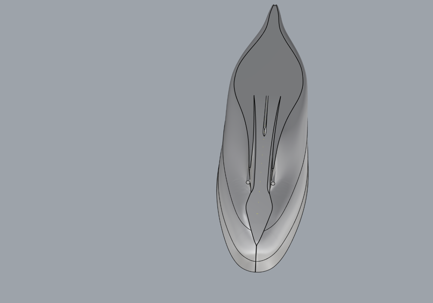
To answer questions: I have a 3D model of the ship in the computer taken from original plans. I have collected images of over 2,000 original blueprints. My 3D model is based on molded lines. The plating in the real world would zigzag across the molded lines. At the keel, it would go 2-inches outside the lines. At the sides, it would be at most an 1 1/2 inches outside the lines. So the real world plating thickness would be about 8 thousandths of an inch. The actual plating pattern is an absurd example of designers making things complicated for the sake of making them complicated. Strakes are lapped, rabbeted, and scarfed. The seam between strakes often reverses. The amount of machining just to make the shell was absurd. This kind of gold plated construction is why only four were able to be built during WWII. Even the famous hyper-detailed 1:48 Missouri model at the US Navy Museum shows a smooth hull without plating. I figure that I can do the same at 1:192. Plus, in the real construction, the shell was built frame on shell. The actual hull form depended upon the accuracy of the mold loft, which ended up being off off by several inches in length in beam. * * * The reality is the shell thickness on any model is going to have to be substantially greater than the scale thickness on the actual ship. Therefore, I would have to reduce the frames to account for a thicker shell. It might be interesting to have the upper part of the shell made out of brass so that the extension of the sheer strake above the deck would not be massively overscale. My computer and ship plan knowledge greatly exceeds my model shipbuilding knowledge. I don't have a place in my house where I can build things. I just have computers. I am trying to come up with a means for building a model of a steel hulled ship. What material? How thick? How many layers are needed? One objective here is accuracy (while sacrificing precision). You can already get kits in this scale but the mass-produced kits are WAY off. I had originally thought about having people CNC a glued up block of wood but all the vendors I have contacted have said this is impracticable for this size and that at least a 4-axis CNC machine is required. However, I see Bluejacket has carved hull kits of 510" "destroyers." I hope this clarifies. -
mtaylor reacted to a post in a topic:
Offset for Hull Thickness
-
I have had requests to make patterns for laser cutting frames for a plank on bulkhead 1:192 battleship hull. That comes out to about 4' 8" long. I am not experienced in building such ships. What I am wondering is how much of an offset should there be on the frames the hull thickness. I bought a NIP book on building a model of the Thunderer. Yet that topic is completely overlooked in the book. When I raise this issue, people seem to think I am just being obstructive. I know if, I just do it, and the offset is 1/8" off from how it has to be planked, the end product will be a noticeable scale 4' off and I will get @#$@#. I would like to be able to say: 1. Here is the pattern. Cut the frame out. 2. Go to {this store} and buy strips in "{this thickness]" {and maybe this thickness} 3. After assembling the frames put down {one layer of this thickness} {? A second layer of this thickness} Therefore, I ask of those who might have experience, how much of an offset should there be? How many layers and of what thickness of wood should go over the hull? Where can such material be purchased? I can even add, what thickness plywood should be used to make the frames?