mikiek Posted January 12, 2016 Share #1 Posted January 12, 2016 (edited) Hi Everyone - I'm working on the Niagara masts and have a few questions. This is really the first time I've looked at the mast plans closely. 1. Plans show quite a few chocks (masts & spars) most are less than 1/16" tall. I'm debating whether to use wood (easy but would damage easy) or brass cut from strip (would take longer but more durable) 2. Plans show sheaves in the masts - even one in the skinny end of the top gallant. At 1:64 scale trying to do something like that ain't gonna be easy. Suggestions? 3. I've got the main top assembled, cheeks on the main mast and was going to glue down the top. The main cheeks provide an 11* angle. The main is also tapered. How in the heck do you get the top horizontally squared with the mast? I was just going to "eyeball it" but I'm afraid even a slight variance will come back to bite me when I start the rigging. 4. The plans keep using "P/S" i.e. chock P/S, cleat P/S . What is P/S? I also made a jig that helped me with cutting octagonal sides on a tapered stick. There are plenty of pix showing a 90* notch taken out of a long piece of wood. You drop your square (maybe round too) stick in and file the side facing up. My problem with that is I would need quite a few different sized notches for the various sized masts and spars and a tapered stick presents some problems. Below are some pix of my solution. Maybe everyone does this but I SWEAR I didn't purposely steal it. It has helped a lot as I have all my masts shaped using just the 2 jigs - one small & one large. All you do is tighten or loosen the nuts on the ends so one end is a little wider than the other. You put the fat end of your tapered stick in the wide end of the jig. With a little adjustment, the side of the stick facing up will be parallel with the top of the jig. Then you can file or sand from one end to the other. The springs in between the wood pieces of the jig keep them from moving once they are adjusted. Not scientific or calibrated. You still must adjust by eye, but I do a lot of that anyway. You can see in a few of the pix, I get nice sharp edges. Edited January 12, 2016 by mikiek dgbot, thibaultron, mrjimmy and 8 others 11 Quote Sail on...... Mike "Dropped a part? Your shoe will always find it before your eyes do" Current Builds: Completed Builds: Lancia Armata 1803 - Panart US Brig Niagara - Model Shipways ; Section Deck Between Gun Bays - Panart ; Arrow American Gunboat - Amati Riva Aquarama - Amati T24 RC Tugboat ; Hispaniola - Megow - Restoration ; Trajta - by Mikiek - Marisstella ; Enterprise 1799 - Constructo Link to comment Share on other sites More sharing options...
mikiek Posted January 12, 2016 Author Share #2 Posted January 12, 2016 For #1, I completely forgot about styrene. Easy to cut, shape, more durable than wood. One problem solved. Would still like to know what material was used back in the day. Canute 1 Quote Sail on...... Mike "Dropped a part? Your shoe will always find it before your eyes do" Current Builds: Completed Builds: Lancia Armata 1803 - Panart US Brig Niagara - Model Shipways ; Section Deck Between Gun Bays - Panart ; Arrow American Gunboat - Amati Riva Aquarama - Amati T24 RC Tugboat ; Hispaniola - Megow - Restoration ; Trajta - by Mikiek - Marisstella ; Enterprise 1799 - Constructo Link to comment Share on other sites More sharing options...
Jaager Posted January 12, 2016 Share #3 Posted January 12, 2016 P/S = port & starboard it is calling for bilateral symmetry for the subject components. Canute and mtaylor 2 Quote NRG member 45 years Current: HMS Centurion 1732 - 60-gun 4th rate - Navall Timber framing HMS Beagle 1831 refiit 10-gun brig with a small mizzen - Navall (ish) Timber framing The U.S. Ex. Ex. 1838-1842 Flying Fish 1838 pilot schooner - framed - ready for stern timbers Porpose II 1836 brigantine/brig - framed - ready for hawse and stern timbers Vincennes 1825 Sloop-of-War - timbers assembled, need shaping Peacock 1828 Sloop-of -War - timbers ready for assembly Sea Gull 1838 pilot schooner - timbers ready for assembly Relief 1835 ship - timbers ready for assembly Other Portsmouth 1843 Sloop-of-War - timbers ready for assembly Le Commerce de Marseilles 1788 118 cannons - framed La Renommee 1744 Frigate - framed - ready for hawse and stern timbers Link to comment Share on other sites More sharing options...
jbshan Posted January 12, 2016 Share #4 Posted January 12, 2016 I made square blank stock, then marked and cut (plane, sand, whatever) the taper on opposing sides. Turn 90 degs., mark and cut the taper there, so now I have square stock, but with the taper cut in. From that square, it isn't too hard to go to an octagon then to round where required. I didn't try to taper and octagon at the same time. I don't have progress pics, but the results can be seen here: http://modelshipworld.com/index.php/topic/9953-lexington-by-jbshan-dlumberyard-164-from-the-seaways-practicum-by-clay-feldman/?view=findpost&p=295786 mtaylor, Canute and Tadeusz43 3 Quote Joel Sanborn http://modelshipworld.com/index.php/topic/9953-lexington-by-jbshan-dlumberyard-164-from-the-seaways-practicum-by-clay-feldman/ Link to comment Share on other sites More sharing options...
mikiek Posted January 13, 2016 Author Share #5 Posted January 13, 2016 Jaager - Perfect! Thank you! jbshan - I think I'm doing the same thing. I plane the square stick down to proper size (still a square), taper that and then mark and sand the octagon. I was having problems sanding level, smooth surfaces. After a little adjustment, the jig allows me to sand away. The top surfaces of the jig stop me from sanding too far or getting crooked. I've tried sanding and filing completely by hand, but my "flat" surfaces always end up a little rounded or one edge is higher than the other. I probably just don't have the technique, so the jig keeps me under control. mtaylor and allanyed 2 Quote Sail on...... Mike "Dropped a part? Your shoe will always find it before your eyes do" Current Builds: Completed Builds: Lancia Armata 1803 - Panart US Brig Niagara - Model Shipways ; Section Deck Between Gun Bays - Panart ; Arrow American Gunboat - Amati Riva Aquarama - Amati T24 RC Tugboat ; Hispaniola - Megow - Restoration ; Trajta - by Mikiek - Marisstella ; Enterprise 1799 - Constructo Link to comment Share on other sites More sharing options...
mikiek Posted January 19, 2016 Author Share #6 Posted January 19, 2016 I'd still like to hear your suggestions for the first 2 questions. Please chime in if you can! Quote Sail on...... Mike "Dropped a part? Your shoe will always find it before your eyes do" Current Builds: Completed Builds: Lancia Armata 1803 - Panart US Brig Niagara - Model Shipways ; Section Deck Between Gun Bays - Panart ; Arrow American Gunboat - Amati Riva Aquarama - Amati T24 RC Tugboat ; Hispaniola - Megow - Restoration ; Trajta - by Mikiek - Marisstella ; Enterprise 1799 - Constructo Link to comment Share on other sites More sharing options...
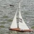
JerseyCity Frankie Posted January 21, 2016 Share #7 Posted January 21, 2016 Not sure what you mean by "chocks"? Do you mean Cleats? Cleats being the single-piece two horned object used to belay a line. Its fairly easy to make cleats with thin stock and a needle file. The actual Niagara is unlikely to have used metal cleats, in my opinion. As to the sheaves in the spars, I know some very very detail-oriented modelers have put actual sheaves into scale masts but most of us simply drill a hole through and reave the rigging through the hole. Or if you want to go into more detail you can widen the edge of the drilled hole with the tip of an ex-acto into a rectangular opening, paint the inside black. The top should be parallel with the surface of the water ( or is it the deck below? anyone?) NOT square to the mast, which is raked. I found this schematic showing the rake of the masts and the attitude of the tops to the masts. Canute and mtaylor 2 Quote Quote Niagara USS Constitution Link to comment Share on other sites More sharing options...
mikiek Posted January 21, 2016 Author Share #8 Posted January 21, 2016 JC Frankie - the plans have cleats and chocks. A lot of times one of each is in the same area (masts, yards, etc) and it's not just 1 or 2. There are lots of them. As best I can see they are shown as some sort of parallelogram about 1/8" long and 1/16" tall. Too small to show any real detail of what it might look like. I've checked a few books but have not found anything helpful. Googling does pull up some info but the pix seem to show the modern day variety. It would be better to see what one looked like from that period. The kit supplies Britannia cleats that are supposed to be painted Buff, so I guess that's supposed to represent wood. Thanks for the details on the sheaves. That helps. Like you said, it just depends on how anal I want to get with them. I did go ahead and glue down the main top. You're right, with the mast rake the top would not be perpendicular to the mast when viewing from the side. However when viewing from the bow or stern the top would still look perpendicular. But you are right - I think parallel to the deck would be the right call. mtaylor and Canute 2 Quote Sail on...... Mike "Dropped a part? Your shoe will always find it before your eyes do" Current Builds: Completed Builds: Lancia Armata 1803 - Panart US Brig Niagara - Model Shipways ; Section Deck Between Gun Bays - Panart ; Arrow American Gunboat - Amati Riva Aquarama - Amati T24 RC Tugboat ; Hispaniola - Megow - Restoration ; Trajta - by Mikiek - Marisstella ; Enterprise 1799 - Constructo Link to comment Share on other sites More sharing options...
popeye2sea Posted January 22, 2016 Share #9 Posted January 22, 2016 Are you referring to cleats that are used to keep a line from slipping down or along a spar? If so then depending on the location and the size of the line they are holding back they will have different sizes. I think in general they have a rectangular shape with a flat face against the line being held and the rear is tapered toward the spar. Perhaps a picture of what you are referring to will help to get the correct answer. Regards, mtaylor and Canute 2 Quote Henry Laissez le bon temps rouler ! Current Build: Le Soleil Royal Completed Build: Amerigo Vespucci Link to comment Share on other sites More sharing options...
mikiek Posted January 22, 2016 Author Share #10 Posted January 22, 2016 I'll get pic of the plan sheet Henry. I just get a little nervous posting pics of copyrighted stuff. I guess just a small portion of a plan isn't going to hurt. The chocks I remember sailing small boats were 3-4 inch long strips mounted long ways on a surface. A grove was cut in the strip - wider than a rope at one end a tad narrower than the rope at the other. You could mash a taught rope into the grove and let go. The tension of the rope would jam it in the narrow end so the chock would hold the rope. That sounds sort of like what you are describing. mtaylor and Canute 2 Quote Sail on...... Mike "Dropped a part? Your shoe will always find it before your eyes do" Current Builds: Completed Builds: Lancia Armata 1803 - Panart US Brig Niagara - Model Shipways ; Section Deck Between Gun Bays - Panart ; Arrow American Gunboat - Amati Riva Aquarama - Amati T24 RC Tugboat ; Hispaniola - Megow - Restoration ; Trajta - by Mikiek - Marisstella ; Enterprise 1799 - Constructo Link to comment Share on other sites More sharing options...
popeye2sea Posted January 22, 2016 Share #11 Posted January 22, 2016 What you described is called a jam cleat. What year was your vessel built? Those are more of a modern fitting. Regards, Canute 1 Quote Henry Laissez le bon temps rouler ! Current Build: Le Soleil Royal Completed Build: Amerigo Vespucci Link to comment Share on other sites More sharing options...
mikiek Posted January 22, 2016 Author Share #12 Posted January 22, 2016 Henry - I believe it was 1812 - 1813 Canute 1 Quote Sail on...... Mike "Dropped a part? Your shoe will always find it before your eyes do" Current Builds: Completed Builds: Lancia Armata 1803 - Panart US Brig Niagara - Model Shipways ; Section Deck Between Gun Bays - Panart ; Arrow American Gunboat - Amati Riva Aquarama - Amati T24 RC Tugboat ; Hispaniola - Megow - Restoration ; Trajta - by Mikiek - Marisstella ; Enterprise 1799 - Constructo Link to comment Share on other sites More sharing options...
mikiek Posted January 22, 2016 Author Share #13 Posted January 22, 2016 Henry - if you check Ken's Niagara build log Page 8, post #160, the 3rd picture from the top, right about the middle of the plan page you can see a chock called for on the mast. This is similar to chocks called for on other components. They all look like little bumps on whatever surface they are on. I suppose I should PM Ken and see what he did. Canute 1 Quote Sail on...... Mike "Dropped a part? Your shoe will always find it before your eyes do" Current Builds: Completed Builds: Lancia Armata 1803 - Panart US Brig Niagara - Model Shipways ; Section Deck Between Gun Bays - Panart ; Arrow American Gunboat - Amati Riva Aquarama - Amati T24 RC Tugboat ; Hispaniola - Megow - Restoration ; Trajta - by Mikiek - Marisstella ; Enterprise 1799 - Constructo Link to comment Share on other sites More sharing options...
JerseyCity Frankie Posted January 22, 2016 Share #14 Posted January 22, 2016 Here is the photo in question and to my surprise I see Model Shipways is calling that Cleat a Chock. I wonder why? Now I see where the confusion is coming from. That IS a Mast Cleat. It is to keep the after portion of the Main Stay from slipping down on top of the shroud gang on the Bolsters while preserving the line of the lead down to the bow. its literally just a wedge shaped piece of wood nailed onto the back of the mast. Its blunt end acts as a little shelf that prevents the loop of the stay from sliding down. Canute and mtaylor 2 Quote Quote Niagara USS Constitution Link to comment Share on other sites More sharing options...
jbshan Posted January 22, 2016 Share #15 Posted January 22, 2016 I would call that a stop cleat. It stops the stay eye from sliding farther down the mast. The yard arms should have them as well, to keep the earrings, braces etc. from sliding farther inward along the yard. As stated, it's just a wedge nailed to the spar. mtaylor and Canute 2 Quote Joel Sanborn http://modelshipworld.com/index.php/topic/9953-lexington-by-jbshan-dlumberyard-164-from-the-seaways-practicum-by-clay-feldman/ Link to comment Share on other sites More sharing options...
popeye2sea Posted January 23, 2016 Share #16 Posted January 23, 2016 You will find them in lots of places. There may be several on the bowsprit for the gammoning and the fore stay. Possible also at the base of the main mast for the mizzen stay Canute, jbshan and mtaylor 3 Quote Henry Laissez le bon temps rouler ! Current Build: Le Soleil Royal Completed Build: Amerigo Vespucci Link to comment Share on other sites More sharing options...
mikiek Posted January 23, 2016 Author Share #17 Posted January 23, 2016 Goo information from all three of you. I did find something in Darcy Lever's book that looked similar and in about the same place. He called it a cleat. Yes they are on the masts, yards, bowsprit and probably other places I haven't gotten to yet. So just a wedge shaped piece of stick is a good enough representation? Just asking because some look a little different than others on the plans (see pix below) I also have a follow up question on the sheaves in the masts. The first pic below shows a sheave in the top and top gallant masts near the foot. Does the notch for these go straight through from the octagonal side shown to the opposing octagonal side. My first reaction to the plans was that I am looking at the notch head on and that it goes straight back, not through the mast. I would be pretty nervous trying to drill through the mast at that angle - even with a drill press. Thanks for all the feedback! This has been a helpful thread for me. Canute and mtaylor 2 Quote Sail on...... Mike "Dropped a part? Your shoe will always find it before your eyes do" Current Builds: Completed Builds: Lancia Armata 1803 - Panart US Brig Niagara - Model Shipways ; Section Deck Between Gun Bays - Panart ; Arrow American Gunboat - Amati Riva Aquarama - Amati T24 RC Tugboat ; Hispaniola - Megow - Restoration ; Trajta - by Mikiek - Marisstella ; Enterprise 1799 - Constructo Link to comment Share on other sites More sharing options...
popeye2sea Posted January 24, 2016 Share #18 Posted January 24, 2016 I think a wedge shaped piece will suffice for all. They pretty much share the same shape. Just remember to put the wider, untapered end towards the line. The sheave hole in the top and topgallant masts is for the top rope. It is what is used to hoist the mast into place. Once the mast is raised high enough a fid is inserted through the fid hole below the sheave. The fid extends beyond the mast on both sides. The mast is then lowered back down until the fid is resting on the trestle trees. That is what holds the mast up. Long winded answer I know, but it helps to know what the parts do so that you can represent them properly. That said, I believe that the sheave for the top rope goes right through the center of the mast. Otherwise the pull will be off center and the mast would not be hoisted straight up. You will probably find that there is an eyebolt under the mast cap on either side of of the mast. You will also notice that they are offset from each other. One is more forward than the other. One side takes the end of the top rope, the other takes a block for the top rope. If you follow the line from the eyebolt through the sheave in the topmast and back up to the block on the other side you will see that will pass through the topmast at an angle. Et voila, that is the angle that your sheave hole must pass through the topmast. The top rope sheave is set into the octagon portion in order to give the rope clearance to pass between the topmast and the trestle trees while the mast is being hoisted into position. Regards, mtaylor and Canute 2 Quote Henry Laissez le bon temps rouler ! Current Build: Le Soleil Royal Completed Build: Amerigo Vespucci Link to comment Share on other sites More sharing options...
mikiek Posted January 28, 2016 Author Share #19 Posted January 28, 2016 One more sheave question. Or maybe it's a modeling question. Let's say for a moment that I did want to fully detail the sheaves in the masts, including the wheel and pin. How in the world does someone cut a notch that thin in a mast that's about 1/8" thick ??? Canute and whaynes 2 Quote Sail on...... Mike "Dropped a part? Your shoe will always find it before your eyes do" Current Builds: Completed Builds: Lancia Armata 1803 - Panart US Brig Niagara - Model Shipways ; Section Deck Between Gun Bays - Panart ; Arrow American Gunboat - Amati Riva Aquarama - Amati T24 RC Tugboat ; Hispaniola - Megow - Restoration ; Trajta - by Mikiek - Marisstella ; Enterprise 1799 - Constructo Link to comment Share on other sites More sharing options...
BANYAN Posted January 28, 2016 Share #20 Posted January 28, 2016 (edited) Hi Mikie, One way is to mark the small line for the slot, dimple the start point for several drill holes (to stop the bit wandering) and drill out a series of small holes along the line with the appropriately sized micro-drill bit - ensure one hole is at the near top and bottom of the slot. use a sharp blade to score the edge of the slot and cut out the waste; finish with a small file. If you have a mill this can be a lot easier - just ensure you set up the piece in the vice/holding jig on the sliding table accurately. That's how I did mine (at scale 1:60). cheers Pat Edited January 28, 2016 by BANYAN mtaylor and Canute 2 Quote If at first you do not suceed, try, and then try again!Current build: HMCSS Victoria (Scratch) Next build: HMAS Vampire (3D printed resin, scratch 1:350) Built: Battle Station (Scratch) and HM Bark Endeavour 1768 (kit 1:64) Link to comment Share on other sites More sharing options...

Recommended Posts
Join the conversation
You can post now and register later. If you have an account, sign in now to post with your account.