xodar461 Posted January 4, 2021 Author Share #91 Posted January 4, 2021 Hi Kirill Thanks for your input on the bowsprit. BTW, your galleon is amazing. The length of the bowsprit in kit is 363 mm. An often used reference for me is Historic Ship Models by Wofram zu Mondfeld. According to his tables of mast dimensions, an English galleon of 1570 would have a bowsprit length of 2.235 x the ship's beam. Using my model as a reference, I measured a the beam to be ~160 mm which would translate to a bowsprit length of 357 mm. The diameter of the bowsprit at the deck would be 0.028 x L of bowsprit, or ~10 mm, which is what the kit calls for. I did not do this for all of the masts and yards as this kit was designed for Amati by Chris Watton, a master model designer (see his website at Vanguard Models). His models are first rate and I trust that he did his research when designing the kit. It is good to know that his measurements are accurate with the bowsprit as I am sure they are with the remaining masts and yards. Jeff Quote Link to comment Share on other sites More sharing options...
kirill4 Posted January 5, 2021 Share #92 Posted January 5, 2021 (edited) Good day Jeff, Thanks for information abt this model , I didn't know about designer of this kit - It looks like this Revenge model designed by Chris Watton almost identical to R.Hoeckel's Revenge reconstruction/ model, as seems to me they are like twin brothers! 😆 exept Chris Watton didn't fitt his model with topgallants which is quite correct for english galleon of that period and in case of northen area of operation... returning to bowsprit length , I still don't understand, if all calculations correct, how than spritsail will work when bowsprit such short and there is no room for the sail....just for fun I've checked some contemporary pictures with galleons... and it looks like bowsprit in this kit somehow lost 2-3 cm of its nessesary length... I dodn't insist on my sugestions, just strange for me ... at least , if You are not going to fitt your model with sails , such short bowsprit and as consequence wrong location of spritsail yard will be not important... Edited January 5, 2021 by kirill4 GrandpaPhil and Bill Morrison 2 Quote Current Build: Spanish Galleon, Lee, 1:100 https://modelshipworld.com/index.php?/topic/6262-spanish-galleon-1607-by-kirill4-lee-plastic-1100/& https://karopka.ru/forum/forum190/topic10341/ Dutch 16-17 Arts Sailing Vessels in details https://www.rijksmuseum.nl/en/rijksstudio/1845326--kirill-shabanov/collections/arts Link to comment Share on other sites More sharing options...
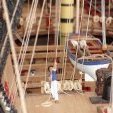
xodar461 Posted January 5, 2021 Author Share #93 Posted January 5, 2021 Hi Kirill Your second post really got me thinking so i decided to check things out. First I marked where the bowsprit met the deck and then measured that compared to the height of the foremast from deck to cap as you suggested. I found that the bowsprit was just a few MM short from the top of the cap so I think I have the correct length. So then I placed the bowsprit in it's deck opening and hung the spritsail yard and this is what I came up with... This seems to be close to the correct position as seen in your reference photos. I think the problem lies with the prototype on the box as I agree that the spritsail yard seems to be in the wrong place (as it is on my kit box top). Let me know what you think and thanks for your input Jeff GrandpaPhil, BenD and Bill Morrison 3 Quote Link to comment Share on other sites More sharing options...
kirill4 Posted January 6, 2021 Share #94 Posted January 6, 2021 Good day Jeff, Oh yes! On your last posted picture bowsprit length looks quite proportional ! And spritsail yard position on this picture seems correct! Now I understood that the problem lies with the prototype on the box, but they did nessasary correction in the actual kit! Very good!!! I'm Sorry for that too intensive inputs regarding bowsprit length from my side :))) just was afraid to see model spoiled by unproportional rigs :))) Do You plan to fitt sails on your model? All the best!!! Quote Current Build: Spanish Galleon, Lee, 1:100 https://modelshipworld.com/index.php?/topic/6262-spanish-galleon-1607-by-kirill4-lee-plastic-1100/& https://karopka.ru/forum/forum190/topic10341/ Dutch 16-17 Arts Sailing Vessels in details https://www.rijksmuseum.nl/en/rijksstudio/1845326--kirill-shabanov/collections/arts Link to comment Share on other sites More sharing options...
xodar461 Posted January 6, 2021 Author Share #95 Posted January 6, 2021 Hi Kirill I appreciate your help and loved the historical paintings you provided. I do plan to put sails on. I plan on having the ship displayed at anchor with the sails partially drawn up, maybe the mizzen or bonaventure sails furled. I plan on using silkspan as the sail cloth provided in the kit is out of scale (much too thick). I have a sheet of plexiglass with the waterline cut out that the ship will sit in that will eventually be finished to simulate water (I hope). I have a phot of this that I will soon post. Never have done sails so that will be an adventure. The kit provides pretty good sail plans and I have several references to help with the rigging if the kit plans are lacking. Jeff Bill Morrison 1 Quote Link to comment Share on other sites More sharing options...
kirill4 Posted January 6, 2021 Share #96 Posted January 6, 2021 Good day Jeff, It will be interesting , upcoming sails making adventure !!! I've made main from percale cotton... I think kit's rigging plan is good , must be good! :))) and for more information ,if ness-ry ,we always have these very detailed historical paintings and R.C.Anderson book which gives us accurate description of each rope of standing and running rigging ... there is very interesting ,high level model of flemish galleon made by Igor Capinos, exelent source of various details could be seen ! http://sailmodel.ho.ua/galleon/index.htm Bill Morrison, GrandpaPhil and md1400cs 3 Quote Current Build: Spanish Galleon, Lee, 1:100 https://modelshipworld.com/index.php?/topic/6262-spanish-galleon-1607-by-kirill4-lee-plastic-1100/& https://karopka.ru/forum/forum190/topic10341/ Dutch 16-17 Arts Sailing Vessels in details https://www.rijksmuseum.nl/en/rijksstudio/1845326--kirill-shabanov/collections/arts Link to comment Share on other sites More sharing options...
kirill4 Posted January 9, 2021 Share #97 Posted January 9, 2021 (edited) guys, just tried to make opposite translation from english to russian my posts...it looks like abracadabra of10-15%my written text I'm very sorry for inconvinience when you are reading my "english" posts 🤪 Edited January 9, 2021 by kirill4 Quote Current Build: Spanish Galleon, Lee, 1:100 https://modelshipworld.com/index.php?/topic/6262-spanish-galleon-1607-by-kirill4-lee-plastic-1100/& https://karopka.ru/forum/forum190/topic10341/ Dutch 16-17 Arts Sailing Vessels in details https://www.rijksmuseum.nl/en/rijksstudio/1845326--kirill-shabanov/collections/arts Link to comment Share on other sites More sharing options...
xodar461 Posted January 9, 2021 Author Share #98 Posted January 9, 2021 Greetings Kirill, your English is just fine in your posts and I have enjoyed reading them! Lower shrouds of the fore mast are now complete as are the futtocks. First 2 pics show how I keep the ratlines even. Next 2 show the final result. You may notice that the tackles have been undone on the photos above. They would have gotten in the way when the ratlines are placed so they were temporarily disconnected from the channel. This can be seen with the main tackles in the next 2 photos. The fore tackles were replaced upon completion of the ratlines. The ratlines have also been painted black. For the purist they were usually tan or light brown but I've always liked the look of black. The lighter color seems to be distracting. The next 2 pics show the foremast catharpins. These were a bit of a challenge to do as a small rope goes through each dead eye opening and then is tied to the shrouds. The deadeyes are 3mm and the blocks are 2 mm. The lanyard (0.1mm rope) is supposed to be tied to the space between the block and deadeye but I tied it to a shroud above the futtock stave (pic 3 below). Work in progress on the futtock shrouds below As I've said in an earlier post, I would like to ultimately display the ship at anchor in the simulated ocean. Here is what I have so far - 5 mm plexiglass with the waterline cutout. Eventually it will be painted and some water details added (first to be done on a test piece or 2). This is still quite some time in the future. until next time, Jeff kirill4, Baker, Bill Morrison and 5 others 7 1 Quote Link to comment Share on other sites More sharing options...
Baker Posted January 10, 2021 Share #99 Posted January 10, 2021 looks very good Jeff. Congrats on your work kirill4 1 Quote Regards, Patrick Finished : Soleil Royal Heller 1/100 Wasa Billing Boats Bounty Revell 1/110 plastic (semi scratch) Pelican / Golden Hind 1/45 scratch Current build : Mary Rose 1/50 scratch Gallery : Revell Bounty Pelican/Golden hind 1/45 scratch To do : Prins Willem Corel, Le Tonnant Corel, Yacht d'Oro Corel, Thermopylae Sergal Shore leave, non ship models build logs : ADGZ M35 funkwagen 1/72 Einhets Pkw. Kfz.2 and 4 1/72 Autoblinda AB40 1/72 122mm A-19 & 152mm ML-20 & 12.8cm Pak.44 {K8 1/2} 1/72 10.5cm Howitzer 16 on Mark. VI(e) Centurion Mk.1 conversion M29 Weasel 1/72 SAM6 1/72 T26 Finland T26 TN 1/72 Autoprotetto S37 1/72 Opel Blitz buses 1/72 Boxer and MAN trucks 1/72 Hetzer38(t) Starr 1/72 Si vis pacem, para bellum Link to comment Share on other sites More sharing options...
kirill4 Posted January 10, 2021 Share #100 Posted January 10, 2021 Perfect!!! Looks Very Good!!! I read somewhere that talreps/ or deadeyes lanyards of standing rigging tarred all the way as well... means not only ratlines could be dark colors... I didnt darkening lanyards on my model...may be need to do it Quote Current Build: Spanish Galleon, Lee, 1:100 https://modelshipworld.com/index.php?/topic/6262-spanish-galleon-1607-by-kirill4-lee-plastic-1100/& https://karopka.ru/forum/forum190/topic10341/ Dutch 16-17 Arts Sailing Vessels in details https://www.rijksmuseum.nl/en/rijksstudio/1845326--kirill-shabanov/collections/arts Link to comment Share on other sites More sharing options...
xodar461 Posted January 28, 2021 Author Share #101 Posted January 28, 2021 Greetings! Fore top mast shrouds now complete Onto the main mast. photo below shows the developing birds nest of lines while i do the shrouds and lanyards. The first 4 are in place and the aft 4 have been secured at the mast head and marked (see blue tape) so as not to mix them up when it comes time to do the lanyards. My process is to first serve the appropriate length that goes around the masthead, then seize it close to the masthead and the bring them through the top, alternating side to side beginning on the starboard. The shrouds are left long and are used to mark where the chainplate is nailed to the wale. The lower deadeye is then placed in the channel and the chainplate fixed to the deadeye and nailed to the wale (some trial and error required to get the correct length). An estimate is made for the correct shroud length and the eye seizing is placed and the shroud is tightened to the deadeye. With only the eye seizing in place, this can be adjusted later if needed. The lanyard is then placed and tightened and measurements taken to insure correct spacing. Only when all the deadeyes are in place and correctly space is the shroud seized and lanyard completed. also note the main tackles have been taken off the hook on the channel as they will be in the way for work on the shrouds and foot ropes. Jeff GrandpaPhil, yvesvidal, Cirdan and 2 others 5 Quote Link to comment Share on other sites More sharing options...
xodar461 Posted February 13, 2021 Author Share #102 Posted February 13, 2021 Greetings! work in progress on the main shrouds. futtock shrouds also mostly done on one side. I left the rope and seizing natural color so as to better see how the shrouds run and how they are seized to the main shrouds Jeff GrandpaPhil, Jacob_Yao, Ondras71 and 6 others 9 Quote Link to comment Share on other sites More sharing options...
xodar461 Posted September 4, 2021 Author Share #103 Posted September 4, 2021 (edited) Greetings... Work on the Revenge has been a bit sporadic over the past few months. Now that the shrouds and ratlines are complete, progress should be a a slightly faster pace. Here is a photo of the ship at this stage... Next up are the stays. Photo below is the main stay (2 mm) with mouse (the part that goes around the mast is served) and it's collar which is served in it's entirety. Note the eye splice in each. The bowsprit gammoning has also been placed. I have to be very careful when turning the ship so as not to snap anything off! I'll post a few more pics after the stays are complete. jeff Edited September 4, 2021 by xodar461 DARIVS ARCHITECTVS, Bill Morrison, Ondras71 and 9 others 12 Quote Link to comment Share on other sites More sharing options...
James H Posted September 4, 2021 Share #104 Posted September 4, 2021 Bet you love ratlines! Weird there's a cannon sticking through the shrouds. I'd never noticed that before. Quote SAY NO TO PIRACY. SUPPORT ORIGINAL IDEAS AND MANUFACTURERS. KEEP IT REAL! On the bench: HMS Indefatigable - 1794 (production prototype), Vanguard Models - 1:64. On Hold: HMS Winchelsea Double Capstan - Syren Ship Models - 1:48 Finished US Baltimore Armed Privateer Schooner Grecian 1812 (prototype) - Vanguard Models - 1:64 'Zulu' fishing boat, Vanguard Models - 1:64 Fifie' fishing boat, Vanguard Models - 1:64 HMS Flirt 1782, Vanguard Models - 1:64. Duchess of Kingston c.1780 - Vanguard Models - 1:64 HMS Sphinx 1775, Vanguard Models - 1:64 ERYCINA - Plymouth Ketch-Rigged Trawler 1882, Vanguard Models - 1:64. 'Nisha' - The Brixham 'Mumble-Bee' - Vanguard Models 1:64 'Saucy Jack' fishing boat - Vanguard Models - 1:64 Ranger 'Barking Fish Carrier' - 1864 - Vanguard Models - 1:64 Indeterminate: Tender Avos - Master Korabel - 1:72. H.M.S. Victory (production prototype) - Amati - 1:64. HMS Granado 1742 (cross section) - CAFModel - 1:48 Link to comment Share on other sites More sharing options...
Cirdan Posted September 4, 2021 Share #105 Posted September 4, 2021 5 hours ago, xodar461 said: I'll post a few more pics after the stays are complete. Great! 😃 Quote Link to comment Share on other sites More sharing options...
xodar461 Posted September 4, 2021 Author Share #106 Posted September 4, 2021 James, There is a cannon poking through both the fore and main shrouds. I had to be careful when doing the ratlines to be sure the line of fire was clear. Seems like a recipe for disaster should should a shot take out one of the lines but who am I to question Chris's design! jeff Robp1025 1 Quote Link to comment Share on other sites More sharing options...
xodar461 Posted November 24, 2021 Author Share #107 Posted November 24, 2021 Greetings Time for another update. The stays are complete as well as the main stay tackle. Now on to the yards. They were all previously made with their attached block some time ago. As mentioned previously I am going to attempt to hand sails on all of them, partially drawn up but not furled (as if at anchor). Below is my first attempt. This required: making the sail with the bolt ropes and cringles; fixing the sail to the yard; attaching the yard to the mast with the halyard; rigging the clew and buntlines and lastly the martnets. here are a few pics of the final? result. I may need to work on the martnets to get them to hang a bit more naturally. Yard lifts, braces, sheet and tack line still need to be done. Comments / advice on the sail would be much appreciated. I plan on going into a bit more detail on the sail construction with the next one Jeff ccoyle, Bill Morrison, Ondras71 and 7 others 9 1 Quote Link to comment Share on other sites More sharing options...
Baker Posted November 24, 2021 Share #108 Posted November 24, 2021 Great work 👍 Quote Regards, Patrick Finished : Soleil Royal Heller 1/100 Wasa Billing Boats Bounty Revell 1/110 plastic (semi scratch) Pelican / Golden Hind 1/45 scratch Current build : Mary Rose 1/50 scratch Gallery : Revell Bounty Pelican/Golden hind 1/45 scratch To do : Prins Willem Corel, Le Tonnant Corel, Yacht d'Oro Corel, Thermopylae Sergal Shore leave, non ship models build logs : ADGZ M35 funkwagen 1/72 Einhets Pkw. Kfz.2 and 4 1/72 Autoblinda AB40 1/72 122mm A-19 & 152mm ML-20 & 12.8cm Pak.44 {K8 1/2} 1/72 10.5cm Howitzer 16 on Mark. VI(e) Centurion Mk.1 conversion M29 Weasel 1/72 SAM6 1/72 T26 Finland T26 TN 1/72 Autoprotetto S37 1/72 Opel Blitz buses 1/72 Boxer and MAN trucks 1/72 Hetzer38(t) Starr 1/72 Si vis pacem, para bellum Link to comment Share on other sites More sharing options...
kirill4 Posted November 27, 2021 Share #109 Posted November 27, 2021 (edited) Good day Jeff, Great job! Rigging Looks very nice and accurate! *The only remarks I have, blocks on the F. mast look all of the same size? It is doubtfull... at least they looks same sizes on the posted photo , For example, top sail sheets quite a thick rope, almost same as shrouds and their blocks,those which are close to the ends and middle of F .S. yard if I 'm not wrong... should be visually at least in 2 times bigger,than You shown them now... it is personal visual impression, but actual sizes of the ropes and corresponding blocks need to be calculated in advance, if not all calculated but than some of remarcable blocks should looks different, depends on rope size... * shrouds deadeyes lanyards need to be " tarred", do not left them light color * FS yard, if there is shown process of sail furling need to be shown lowered more down, approx 1,5-2 cm... In more lowered than now position You could nicely display how martnets are working...as option,ends of the sail could be shown lifted up by martnets more close to the yard ends, and central part of the sail could be left with some bely... There is a picture of nice and historic accurate made galleon museum model of Elizabeth Jonas, could be used as reference of many interesting details... I think in general, both authors, of this model and your kit used same basic source of information for their reconstructions...:))) Edited November 27, 2021 by kirill4 Bill Morrison, BenD, Cirdan and 2 others 4 1 Quote Current Build: Spanish Galleon, Lee, 1:100 https://modelshipworld.com/index.php?/topic/6262-spanish-galleon-1607-by-kirill4-lee-plastic-1100/& https://karopka.ru/forum/forum190/topic10341/ Dutch 16-17 Arts Sailing Vessels in details https://www.rijksmuseum.nl/en/rijksstudio/1845326--kirill-shabanov/collections/arts Link to comment Share on other sites More sharing options...
xodar461 Posted November 30, 2021 Author Share #110 Posted November 30, 2021 Greetings Kirill Great points, as always. Every time I look at your galleon I am amazed with your work. On more than one occasion I have used it as reference for the Revenge. Re: the blocks at the end of the fore yard, they are indeed the same size as that was what the plans called for. After some thought, I decided to change them on both the fore and main yards to a 6mm block for the topsail sheet at a 4 mm one for the lift. I have some 7 mm blocks but I think visually they look too big. As far as darkening the lanyards the time for that has passed - I don't want to try to darken them up in place and it would be way to much work to redo them. As they are a medium shade of brown I do not think they detract from the overall look. I may use black for my next model (whatever that may be) but I do like the contrast even if it may not be historically correct. And finally, I think I will do as you suggest with the sails similar to the photo above. I will continue to post as things progress. Thanks as always Jeff Quote Link to comment Share on other sites More sharing options...
kirill4 Posted November 30, 2021 Share #111 Posted November 30, 2021 Good day Jeff, All clear,I will be waiting for new photoes of building process... Quote Current Build: Spanish Galleon, Lee, 1:100 https://modelshipworld.com/index.php?/topic/6262-spanish-galleon-1607-by-kirill4-lee-plastic-1100/& https://karopka.ru/forum/forum190/topic10341/ Dutch 16-17 Arts Sailing Vessels in details https://www.rijksmuseum.nl/en/rijksstudio/1845326--kirill-shabanov/collections/arts Link to comment Share on other sites More sharing options...
xodar461 Posted January 14, 2022 Author Share #112 Posted January 14, 2022 Greetings! For anyone interested, here is a brief description of how I made the sails. Comments and posts regarding sails and their construction on MSW were quite helpful as I have never done this before. Starting with a sheet of silkspan, one side was painted with a foam roller and hung to dry (I used some acrylic paint, cream color, that had been used for walls in the house). The kit provides templates for all the sail. These were cut out and glued to cardboard to provide some thickness. The sail outline was then traced onto the silkspan. Seams were marked and drawn onto the sail with the result below. The sail was then cut out with ~5mm overlap that would be folded over to secure the top and bolt ropes. I know this is not how the ropes were attached however at 1:64 scale there is no practical way to sew the rope to the silkspan so I figured this compromise would work. Photo below shows the process with the head rope glued and work on the bolt rope. The flap has been folded over and glued on the left. The bolt rope was one continuous rope from the left upper corner to the right. The clews were easy to make by just leaving a little extra and seizing the rope. The cringles were made by passing a needle with a small thread through the bolt rope at the appropriate intervals (as marked on the sail plan). They are pretty secure once the flap in folded over. This process can be seen below. After the ropes are placed I lightly paint the sail to lessen the prominence of the seam lines (this also makes the foled over flap of silkspan less visible). On my previous post, I think the lines are too visible on the fore course so this extra layer of paint make them a bit fainter. I ended up redoing the this sail for this reason and also because I placed the robands at the seams and after further review, they should be midway between the seams. Photo below shows a close up of a lateen sail and then all the sails. Once the sails were complete I decided to revise the head cringle (or earring) as I did not like the loop as seen in the main topsail (second from bottom). It should look more like the main sail (bottom). I've already got the fore course, topsail and spritsail rigged so more photos to follow Jeff Cirdan, Dave_E, Bill Morrison and 2 others 5 Quote Link to comment Share on other sites More sharing options...
Dave_E Posted January 14, 2022 Share #113 Posted January 14, 2022 Adding sails to a model ship (in my opinion) is an art in itself. I haven’t heard the term yet “model ship sail maker”, but I think it’s a warranted title. Superb work! Cirdan and xodar461 2 Quote Dave Current builds: Rattlesnake Completed builds: Lady Nelson On the shelf: NRG Half Hull Project, Various metal, plastic and paper models Link to comment Share on other sites More sharing options...
xodar461 Posted January 16, 2022 Author Share #114 Posted January 16, 2022 Greetings! Construction continues...below - martnets and buntline on the forward side of the fore course. The Halyard was a bit of work to place as the lanyard and block were placed a long time ago as the knighthead is below deck and unavailable to rig. The first loop around the yard was easy enough...the second one had to be secured with the mast in place and under the correct amount of tension. Not visible is the 1mm brass rod the was placed to hold the yard onto the mast. This also keeps other lines from pulling the yard up. At full scale the yard would have enough weight that this would not happen but at this scale, there is not enough weight to pull the halyard down naturally. On the aft side we have the martnets and the clew lines. Fore course sheets and tacks now attached to the fore course clew. The sheet lines had to be taken down a bit in order to have access to the fore deck for placement of later lines. These ropes were used to pull up the sail to its current position. The sail is lightly sprayed with water making is quite pliable and easy to draw up. It will then dry and keep its shape. It was at this point that I realized I forgot to place the parrel trucks and beads (see photo 2 above). The work was a bit tight however I was able to get them on as can be sen below. The fore yard lifts are also on at this point. Here's a view from the front. Only line left is the bowline which will go on after the topsail and sprit sail are on. Next up, the for topsail. Placing the halyard and lanyards for this is quite the process. Everything has to be checked and rechecked to get the correct tension without pulling the main stay way out of alignment. here's a photo on the work in progress... And finally the topsail ready to rig. One of the issues with sail placement is finding a place to belay all of these lines. Some of the belay points on the plans did not seem to work and in some cases up to 3 lines were to be belayed at the same pin. I was able to make it work with a combination of the belaying pins and the rails and modification of the run of some of the lines (belaying pins may be an anachronism for this period but so be it - leaving them off and tying all of these ropes to the rails is not something I wanted to do). Most of the work on the topsail and sprit sail is complete and I will update with more photos soon Jeff Cirdan, DARIVS ARCHITECTVS, Ondras71 and 5 others 6 2 Quote Link to comment Share on other sites More sharing options...
xodar461 Posted February 8, 2022 Author Share #115 Posted February 8, 2022 Greetings Work continue on the sails. The sprit sail, fore course and topsail lines have been placed except for the bowlines in the following photos. The spritsail is shown partly furled. Here's a photo of some of the lines belayed. In order to remember the size of each line and where it was rigged (in order to make the appropriate coils), I made this cheat sheet to represent each belay point on the fore deck. The name of the line and rope size is listed for each belay point. After the main course was set, I decided to finish the lines to the sprit sail and the fore sails. This included the sprit sail sheet and the fore sail sheet and tack line. Some completed rope coils... forward view of work so far... And finally one of the crew working the sprit sail halyard. Jeff Bill Morrison, Ian_Grant, westwood and 8 others 11 Quote Link to comment Share on other sites More sharing options...
Cirdan Posted February 8, 2022 Share #116 Posted February 8, 2022 Very beautiful model. I like the style very much. Quote Link to comment Share on other sites More sharing options...
westwood Posted February 8, 2022 Share #117 Posted February 8, 2022 That looks great Jeff. I admire your patience and skill. Quote Dusan Currently building: HMS Winchelsea 1764 by westwood - 1:48 Revenge 1577 - by westwood - 1:64 In preparation: Fourth-rate ship 1681 - 1:48 Link to comment Share on other sites More sharing options...
MarcNS Posted February 27, 2022 Share #118 Posted February 27, 2022 Hi Jeff I am new to MSW but have been following your build for a while as a visitor. I am also building this kit at present and while, no where near as ambitious as you, I have appreciated many of the comments and points you have made as its has helped me on numerous occassions. Currently, I am constructing the masts and bowsprit and I do have a question. When I dry fit the bowsprit, it is of course off centre - there seems to be a great deal of play in the fitting so I assume it needs to cross the bow at a particular angle. There do not appear to be any diagrams or pictures from above to guide this. Can I ask how you chose to do it? Your ship is an absolute masterpiece. regards, Marc Quote Link to comment Share on other sites More sharing options...
allanyed Posted February 28, 2022 Share #119 Posted February 28, 2022 Jeff, She is a very well constructed model, congratulations. I do notice there are belaying pins which is curious as they were not used on British ships before 1770 and Revenge ran aground in 1591. Am I correct in assuming this is a kit design error? Thanks Allan Quote PLEASE take 30 SECONDS and sign up for the epic Nelson/Trafalgar project if you would like to see it made into a TV series. Click on http://trafalgar.tv There is no cost other than the 30 seconds of your time. THANK YOU Link to comment Share on other sites More sharing options...
xodar461 Posted March 1, 2022 Author Share #120 Posted March 1, 2022 (edited) Thanks for the comments Marc: In regards to your question, I assume you mean the angle of the bowsprit from horizontal. not sure I can give you the angle but I will let you know the distance the bowsprit is above the stem in a post later today. That may help with the correct angle. Allenyed: I am aware that belaying pins on a ship of this period are likely anachronistic, however I decided to keep them anyway. There are just not enough places to belay all of the lines on the rails and cleats without it looking a mess in my opinion. (The foward rail on the fore deck would have to have 14-15 lines tied to it for example). Even so, the plans call for several lines to be belayed on one pin so these lines were tied to the rail. As the kit was designed by Chris Watton for Amati, it would be interesting to hear his opinion on this subject but I have not inquired. ( I did find one reference of belaying pins found in the wreck of the Mary Rose, so...) Jeff Edited March 1, 2022 by xodar461 additional text) Bill Morrison and Baker 2 Quote Link to comment Share on other sites More sharing options...

Recommended Posts
Join the conversation
You can post now and register later. If you have an account, sign in now to post with your account.