Gregory Posted September 5, 2019 Share #31 Posted September 5, 2019 (edited) FWIW, it looks like that clove hitch would still make a nice knot. Once you seal it with some white glue, you could clip the ends real close to the foot rope.. PS Clip it after you get it into position.. Edited September 5, 2019 by Gregory Quote Luck is just another word for good preparation. —MICHAEL ROSE Current builds: Rattlesnake (Scratch From MS Plans On Hold: HMS Resolution ( AKA Ferrett ) In the Gallery: Yacht Mary, Gretel, French Cannon Link to comment Share on other sites More sharing options...
Bob Cleek Posted September 5, 2019 Share #32 Posted September 5, 2019 55 minutes ago, abelson said: Thanks. I think you misunderstood me. I’m talking about knots on the bowsprit and boom foot ropes. Another builder suggested to simply use separate line to tie each knot. That seems like a good approach. That way the knots can be slid on the rope to achieve the desired spacing and then secured with AC. I’ll try it. I did misunderstand you, thinking you were talking about ratlines and called them foot ropes, then I realized you were talking about foot ropes for working out on spars, sometimes called "horses." I thought I deleted the post, but I guess it survived. Glad it was of some use to you! (Did I mention that tying ratlines is one of the biggest PIA's in all of ship modeling? ) Quote Link to comment Share on other sites More sharing options...
JerseyCity Frankie Posted September 5, 2019 Share #33 Posted September 5, 2019 (edited) This magic trick allows you to tie a series of evenly spaced overhand knots on a line. But you can do it the old fashioned way by just hand-tying individual knots. Headrig footropes are simply pairs of lines hanging down at such a height that a crewperson standing on them has the spar at navel hight. The two ends are hitched over the spar or tied to an eyebolt. They do need to be in pairs though, Port and Starboard. A single rope won’t sufice. Edited September 5, 2019 by JerseyCity Frankie el cid 1 Quote Quote Niagara USS Constitution Link to comment Share on other sites More sharing options...
JerseyCity Frankie Posted September 5, 2019 Share #34 Posted September 5, 2019 Brady’s Kedge-Anchor has details about rigging footropes on the jibboom: https://books.google.com/books?id=YihFAAAAYAAJ&printsec=frontcover&dq=kedge-anchor&hl=en&sa=X&ved=0ahUKEwiQpvHC27jkAhWIiOAKHZ9IBw0Q6AEIJzAA#v=onepage&q=kedge-anchor&f=false J11 1 Quote Quote Niagara USS Constitution Link to comment Share on other sites More sharing options...
abelson Posted September 5, 2019 Author Share #35 Posted September 5, 2019 21 hours ago, Gregory said: FWIW, it looks like that clove hitch would still make a nice knot. Once you seal it with some white glue, you could clip the ends real close to the foot rope.. PS Clip it after you get it into position.. I tried the clove hitch and found it difficult with the rope off-ship. It might be easier with the ropes on-ship. I used simple double knots. Gregory 1 Quote Steven E. Sylven Link to comment Share on other sites More sharing options...
abelson Posted September 5, 2019 Author Share #36 Posted September 5, 2019 I think the purpose of the knots is to prevent slipping. Quote Steven E. Sylven Link to comment Share on other sites More sharing options...
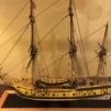
abelson Posted September 25, 2019 Author Share #37 Posted September 25, 2019 (edited) Progress Update: Added the foot ropes to the bowsprit. I made six individual square knots on each rope. I didn’t tighten them so that they could be slid along the rope to the desired spacing (2-feet apart). Once in place, I tightened the knots, added a little CA, and trimmed them. I made a loop in the rope at the end of the bowsprit and seized the lower end of the rope to an eye on the bowsprit cap. One rope is a little longer than the other – no big deal. Next, I fashioned the fore and main mast tackle pendants. I used 0.5 mm black line and 3.5 mm Syren walnut bullseyes for the eye splices. The pendant length was determined by scaling the rigging plan. I fashioned the bridal for the lower yard slings using 1 mm black line and a 5.5 mm Syren heart and set it up for eye splices. As suggested in another builder’s log, I seated the bridal around the mast before the shrouds and stays. With the mast off-ship it was easier to seat the bridal around the mast, but seizing the eye was difficult. Rigged the yard slings as shown in Fig. 38 with 5.5 mm heart. Fitted out the fore and main lower yards. Rigged the footropes and stirrups from 28-gauge wire as recommended in Chuck Passaro’s MS Brig Syren Prototype Build Log. I found wire easier to work with than thread – I like the finished effect. It’s a little frustrating, though, because the wire is so thin it tends to break when twisted. Set the outboard stunsail boom irons in the holes previously drilled in the ends of the yards. These were made from 20-gauge wire. Rigged the Flemish horses with 28-gauge wire. Fitted the yards with tackle pendants. Scaled the length of the pendants from the rigging plan. Seized a 5/32” DB to each pendant. Tied 5/32” single blocks to the main and fore mast yards for the topsail sheet, 1/8” SBs for the clew garnet, and 5/32” SB and 1/8” SB for lifts. Tied 1/8” single blocks to the fore lower yard arm for the leech lines and bunt lines. Note: These are not shown on the rigging plan. Fashioned the main and fore lower yards stunsails from 1/8” dowel. Painted them burnt umber. The inner boom iron was made from 20-gauge wire. Drilled a hole into the yard for the boom iron. Rigged the fore and main topsail yards (including stunsails) and the fore and main topgallant yards. Added pins to the main and fore mast to support the yard arms. I got this idea from rafine’s build log – it took me awhile to figure out what the pins were for – a good idea. Rigged the spritsail yard foot ropes. Fit the spritsail with brace pendants with 5/32” SB. Since I’m following the Rattlesnake rigging plans, I fit the spritsail with a “tye” (See plan). Suspended the spritsail from the jib boom with a truss (Detail H on the FA rigging plan). The ornate detail of the truss is not visible when rigged. Nonetheless, it’s authentic. Note: Be cautious working on the jib boom so as not to dislodge it as I did - no harm, no foul. Added 1/8” SBs to the main top mast trestle tree for the top gallant yard braces. Also, added a pin to the main top mast for the main topsail yard. At this point I'm about six months into the build. What's next? I may concentrate on the strapping the lower deadeyes and fashioning the chain plates. Edited March 16, 2020 by abelson spell check Tigersteve, rafine, Dwight and 3 others 6 Quote Steven E. Sylven Link to comment Share on other sites More sharing options...
Dwight Posted September 26, 2019 Share #38 Posted September 26, 2019 Looks great. The Lauck Street Shipyard "book" was a waste of money , Almost as confusing as the instructions that came with the model Quote Dwight current build : Fair America by Model Shipways Completed Build : 18th Century Armed Longboat by Model Shipways : Armed Virginia Sloop by Model Shipways Under the bench : Syren by Model Shipways ,, Rattlesnake by Model Shipways Link to comment Share on other sites More sharing options...
abelson Posted September 26, 2019 Author Share #39 Posted September 26, 2019 9 hours ago, Dwight said: Looks great. The Lauck Street Shipyard "book" was a waste of money , Almost as confusing as the instructions that came with the model Thanks. Sorry to hear the book was confusing. Agree, the FA instructions are a little confusing. I find myself relying more on build logs than the instructions. The FA rigging is lacking in detail. As I mentioned, I've been using the Rattlesnake rigging plans which are similar to FA but more detailed and differentiate the running rigging (red) from standing rigging (black). Due to my lack of sailing ship knowledge, I spend a lot of time cross referencing the Key To Rigging Plan in the instruction manual and the FA rigging plan to become familiar with the tackles, lifts, braces, backstays, etc. I found a spreadsheet on the internet called 16 Gun Brig Fair American - Standing and Running Rigging (1:48 Scale) that is very informative. It lists the various running and rigging lines, line sizes, and block sizes. Dwight 1 Quote Steven E. Sylven Link to comment Share on other sites More sharing options...
abelson Posted September 27, 2019 Author Share #40 Posted September 27, 2019 (edited) Decided to strap the 3/16” deadeyes. The kit doesn’t come with the 11/32” diameter MS #439 strops noted in Fig. 26B in the instruction manual. Fortunately, I had some left over from my Rattlesnake build. I found them easier to work with than the 0.032" dia. wire that comes with the kit. I used a toothpick to form the lower eye of the strop. I set them temporarily in the channels just for effect. The chain plates are problematic. Modelshipways no longer provides the #991 chain plates noted in Fig. 26B. I had some brass chain plates (see photo) from my Rattlesnake build that would have been perfect, but I don’t have enough of them. I ordered some 15 mm (0.59”) long brass chain plates from MS that I’m hoping I can use. I misplaced the 5/32” dia. deadeyes, so I ordered them as well. [Just a matter note, I have found that MS often overcharges for shipping when you order on-line. Their explanation for this is that they can’t check every order. If you bring it to their attention, they will credit you.] Finished the bowsprit horses. This wasn’t as difficult as I thought it was going to be. I fashioned the bowsprit horse netting from some vail (netting) leftover from my Rattlesnake build. For the wooden spreaders, I used 1/16”x 3/32” planking battens from the kit, cut to 2 feet (1/4” scale) and then halved (lengthwise). I glued the spreaders to the vail 3 feet apart (scaled from the rigging plan). For the horses, I cut two pieces of 0.021” dia. black line long enough (about 6.5”) to span between the bowsprit cap and the knightheads with enough to seize them to eyebolts and to account for the stirrups rigged to the fore stay. I glued each line to the spreaders with CA. I then applied CA to the vail to secure it along the horse line. Then, I trimmed the vail along the spreaders and the horse line with an X-acto . It’s not perfect, but I Iike it. Edited March 16, 2020 by abelson etubino, Tigersteve, Dwight and 2 others 5 Quote Steven E. Sylven Link to comment Share on other sites More sharing options...
abelson Posted October 5, 2019 Author Share #41 Posted October 5, 2019 (edited) Received my order of 15mm brass chain plates. They worked out, but I should have ordered more because some were wasted. They’re brittle. Once you bend them there’s no going back. The lesson learned here - order more than you think you'll need. The difficult part was trying to make them the same length. I stepped the masts in order to determine the slant of each chain plate. I marked the position on the black strake with a fine point awl. I found it easier to set the dead eyes in the channel notches without the chain plates in place and then cap the channels with wood strips. I put a dab of CA on each deadeye strap to keep them from falling off while the channels were capped. I sanded and filed the capping strips and painted them hull tallow. I hooked the chain plates into the deadeye strap eye, pinned them to the black strake and painted them black. I didn’t paint the deadeyes. As a matter of note, I noticed in other build logs that the chain plates are attached to the main whale. So, I thought I erred in attaching the chain plates to the black strake. However, the instruction manual and the plans clearly indicate and show the chain plates being attached to the black strake. I assume, therefore, that the black strake is correct. Although, I do like the appearance of the chain plates attached to the main whale. Spent a considerable amount of time studying the rigging plan, the key to rigging plan, and the belaying pin plan, and cross-referencing them with the 16 Gun Brig Fair American - Standing and Running Rigging (1:48 Scale) spreadsheet. There are a few rigging items in the spreadsheet that do not appear in the key plan, the rigging plan, or the belaying pin plan. To each item in the spreadsheet, I added the corresponding rigging plan key number to the spreadsheet for easy cross-reference. As I matched up the key numbers with the spreadsheet, I highlighted each number on the rigging plan with a yellow marker. I did manage to match up every number on the rigging plan with the spreadsheet. The belaying pin plan and the key to rigging plan use different terminology. Consequently, it’s confusing where some of the lines are belayed. Where I could match them up, I added the rigging plan key numbers to the corresponding belaying pin plan for quick reference. Also, I found it helpful to develop sketches to more clearly illustrate the rigging. I added key numbers, block sizes, and line sizes to the sketch (see example). I feel more confident now with the rigging. Set eyebolts in the port side of the fore and main mast tops for the topgallant tackle and on the P&S sides for the burton tackles. Set eyebolts in the P&S sides of the bulwarks for main and fore lower sail clews. Set eyebolts in the deadeye channels for fore lower yard truss tackles, main and fore tackle runners, fore and main topsail halyard tackles, and fore and main Lower yard tackles. Edited March 16, 2020 by abelson DARIVS ARCHITECTVS, rafine, GrandpaPhil and 2 others 5 Quote Steven E. Sylven Link to comment Share on other sites More sharing options...
abelson Posted October 26, 2019 Author Share #42 Posted October 26, 2019 (edited) Progress update. Fashioned the main and fore mast burton tackle pendants from 0.018" diameter black line. Scaled the length from the rigging plan. Used a toothpick to create the pendant eye. Applied some CA glue to stiffen the eye. Strapped 9" double pendant blocks using 28 gauge wire. Next, I set the fore mast. The fore hole was slightly over-drilled, so I followed the advice of the instruction manual and set a ¾ x 18 brad in the heal of the mast. I drilled a hole in the heal, cut off the brad head, and inserted the brad in the mast hole. I then tapped the mast lightly with a hammer, setting it as plumb and at the proper angle as I could get it - it worked out well. Fabricated the topsail yard parrels as depicted in Fig. 41 of the instruction manual. The parrel ribs were made from 1/32” x 3/32” wood strips (I used some leeway in the shape of them). The parrel trucks are 1/16” glass beads that I had from my Rattlesnake build (the kit doesn’t include these). I painted the ribs burnt umber to match the masts. Fig. 41 says there are 6 ribs per yard. I found only 5 ribs are necessary. I used 0.33 mm (0.012”) hemp to string the ribs and trucks. Note: The ribs and trucks have to be strung on the yard because the line is seized around the yard inside the sling cleats. I created an eye at the end of the parrel as per Fig. 41. The hauling end of the parrel passes through the eye and belayed. This will be done when the yards are rigged aloft. I fit the topsail yard temporarily to see how the parrels aligned. Moved on to fabricating the closed heart and metal strap for the main fore stay. The heart (not provided in the kit) is a laser cut 7/32” boxwood purchased from Syren. The metal strap is 20 gauge (0.032”) wire painted black. Decided to try my hand at making a stay mouse. Cut a length of 0.04” black line for the main stay. Made an eye at one end. Measured the distance of the mouse from the main mast on the rigging plan, multiplied by 2, and allowed for wraparound the mast to get the length from the eye (16 feet at 1/4 scale). Using 0.040” line, tied a knot on the main stay at the 16-foot mark. Using 0.021” line, tied another knot. Using 0.018” line, tied another knot and then wound the line tightly around the knots. Applied CA to secure the line. This made a nice mouse. Unfortunately, and this is where paying close attention to the rigging plan is necessary, the mouse was orientated in the wrong position (see photo). So, I had to start over. Second time’s the charm, as I was able to create the mouse in the correct orientation. I touched up the mouse and eye with black paint. Repeated the process for the main preventer stay and the fore stay (The fore stay is 0.0021” line). Prepared the lower shrouds for rigging. Set up the first-seated, main forward shroud with a deadeye and seized it to a 0.021” line cut over-length to allow for the line to be seated over the mast tackle pendants and to seize a deadeye on the other end. To maintain the plan spacing between deadeyes, I used a deadeye claw made from a paper clip (see photo). I found this simpler than the twisted wire deadeye claw illustrated in Fig. 29B in the instruction manual. I set the first pair of shrouds on the port side instead of starboard side as called for in the instruction manual - oops. Yet, another reason to study the instruction manual. I set up the deadeye lanyards (0.015” black line) as illustrated in Fig. 29B. I repeated the process for the 2nd pair of shrouds on the starboard side. Still to come, the 3rd pair on the port side, and the 4th pair on the starboard side. Oh, one thing I overlooked, the 9” double block beneath the main top for the gaff throat halyard (Item 58 in the Key to Rigging Plan). This would have been much easier to fit when the main top was not aloft. I just looped it around the mast and tied it off. The gaff throat halyard tackle (Item 48) is not clearly shown on the rigging plan. It’s represented by dashed (broken) lines to illustrate that it’s behind the bulwark as viewed on the plan. It consists of a 7” double block and a 7” single block hooked to an eye bolt in the deck and belayed to a pin in the port side pin rail (see sketch). The gaff peak halyard tackle is not shown on the rigging plan nor identified in the Key to Rigging Plan. It’s set up the same as the gaff throat halyard tackle but is belayed to the starboard pin rail (as noted on the Belaying Pin Plan). Edited November 19, 2019 by abelson Added lanyard line size GrandpaPhil, vulcanbomber, DARIVS ARCHITECTVS and 4 others 7 Quote Steven E. Sylven Link to comment Share on other sites More sharing options...
J11 Posted October 26, 2019 Share #43 Posted October 26, 2019 Great images, thanks for posting those, very helpful in constructing those parts mentioned. Your build is coming along nicely! Quote Current build project: CSS Alabama 1/96 https://modelshipworld.com/topic/20148-css-alabama-by-jonathan11-revell-196-scale-kit-bash-90-historical-accuracy/ Finished build projects 2018: H.L Hunley 1/24 CSS Arkansas 1/96 Link to comment Share on other sites More sharing options...
abelson Posted October 27, 2019 Author Share #44 Posted October 27, 2019 (edited) 1 hour ago, Jonathan11 said: Great images, thanks for posting those, very helpful in constructing those parts mentioned. Your build is coming along nicely! Thanks. I’m glad to be of help. Edited October 27, 2019 by abelson J11 1 Quote Steven E. Sylven Link to comment Share on other sites More sharing options...
Dwight Posted October 27, 2019 Share #45 Posted October 27, 2019 So you tried to grab the mouse by the nose instead of the tail. Looks good after you flipped him over. Remember always grab the mouse by the tail. That was just plain silly. abelson 1 Quote Dwight current build : Fair America by Model Shipways Completed Build : 18th Century Armed Longboat by Model Shipways : Armed Virginia Sloop by Model Shipways Under the bench : Syren by Model Shipways ,, Rattlesnake by Model Shipways Link to comment Share on other sites More sharing options...
abelson Posted October 31, 2019 Author Share #46 Posted October 31, 2019 (edited) Following up the last post, I completed the main lower shrouds. The paper clip deadeye claws worked well to get the initial alignment of the deadeyes. With the claw removed and the lanyard reeved, the deadeyes weren’t aligned the same but are close enough for my liking. Getting ahead of myself here, after studying the rigging plan, I decided to make the lower yard trusses. I thought it would be easier to fit these without the yard aloft. Fig. 39 in the instruction manual illustrates how the trusses and pendants are “married” and reeved. The location of the purchases below the yard is not shown on the rigging plan, so it’s left to the builder to decide where to position the blocks. I decided to position them 3 feet below the yard. Note: Page 35 of the instruction manual states the lower lift purchase blocks should be midway between the deck and the lower mast cap (about 16' at 1/4" scale). You could assume that the lower yard truss pendant purchases should be the same. Using 0.021” line, I made an eye on one end, seized it, and applied some CA to it. I cut the line long enough (14’ @ 1/4” scale) to be wrapped around the yard, seized, and reeved through the opposite truss eye. I duplicated this for the 3 trusses. I fit the trusses to main and fore lower yard. The upper purchase blocks (1/8” double) will be seized to the pendants when the yards are suspended. Moved on to the sheer poles. I made the sheer poles from 1/32" x 3/16" plank from the kit, cut down to 1/32" square and painted them black. I glued a shear pole to each main mast shroud just above the deadeyes and seized it to the shrouds. Touched up the poles with black paint to cover the sheen of the CA glue. Completed the main preventer stay and main stay. Used 0.030” line for the preventer stay and 0.018” line for the lanyard. I set up the preventer stay with a 5.5 mm heart (not furnished with the kit) and eye per Detail M on the rigging plan. Note: Fig. 30C shows the preventer stay setup with a bullseye. I choose to follow Detail M. The main stay is 0.050” line set up with a 5.5 mm heart and 0.020” black line lanyard per Detail C. I had previously fashioned the lower heart with metal strap and eye. Next up, the fore lower shrouds. Seized to the main stay the main stay tackle pendent (0.210” black line), 7” double block for the forestay tackle, and four 7” single blocks for the fore topsail braces. These are positioned as shown on the rigging plan. Edited November 1, 2019 by abelson Update DARIVS ARCHITECTVS, J11, GrandpaPhil and 2 others 5 Quote Steven E. Sylven Link to comment Share on other sites More sharing options...
abelson Posted November 22, 2019 Author Share #47 Posted November 22, 2019 (edited) Progress Report: Completed the fore lower shrouds and sheer poles. Set up the fore stay (0.040” black line) with a 5.5 mm heart, 0.015” black lanyard, and bowsprit collar. Fig. 30E shows turns around the lanyard, but Detail N doesn’t show this. I opted not to wrap the lanyard. Fashioned the futtock shrouds as per Detail G on the rigging plan. For me, so far, these are the most challenging part of the rigging – a lot of seizing in a tight area. But I managed to complete them. Phew. I applied a little CA to the futtock stave and positioned it on the shrouds -placing the ship on its side made this easier. I then lashed a 1/32” x 1/32” futtock stave to the lower shrouds. I started with double overhand knots for seizing the stave to the shrouds. I applied CA to the knot and then trimmed the ends with a nail clipper. I didn’t like the bulky look of the knot, so I switched to a single overhand knot. Next, the futtock shrouds were rigged. I used 0.021” black line. I seized a futtock hook, made from 1/16" eyebolts and spray painted black, to one end of the line. I think the hooks are too long, but I’m not changing them. Then I hooked the shroud into the eye formed in the deadeye strop (Fig. 33B) under the top. The loose end is wrapped around the futtock stave and seized to the shroud as shown in Detail G. I added two catharpins seized between the staves (see photo). These are not shown or noted anywhere in the FA instructions or plans. I saw them on Chuck Passaro’s Syren practicum. The catharpins are 0.018” black line. I made the main top mast shrouds (0.021” black line) in the order shown in Fig 33. I used a paper clip claw (jig) to maintain the spacing between the upper and lower eye of the deadeyes (about 1’-9” @ ¼” scale). Like KenW’s FA build, instead of a thimble shown in Fig 33A, I lashed a 1/8” block between the first shroud pair and the second shroud pair for the topsail yard lift. This makes the yard lifts part of the running rigging rather than the standing rigging. The lanyards are 0.015” black line. I added shear poles (1/32" x 1/32") lashed to the top mast shrouds a la the lower shrouds. I added the main topmast stay (0.020” black line) next. The stay passes through the ¼” lead block (Detail I) on the fore mast and is set up with a 5/16” fiddle block, purchase, and a 5/32” single becket block hooked to a eyebolt on the aft side of the fore mast. The purchase is belayed to a cleat on the fore mast. I setup the main topmast backstay (0.020” black line) temporarily with paper clip jig. I plan to reeve the lanyards after the ratlines are completed. Next up, complete the fore top mast shrouds and stays. Stay tuned. Edited March 16, 2020 by abelson spell check J11 and GrandpaPhil 2 Quote Steven E. Sylven Link to comment Share on other sites More sharing options...
abelson Posted December 4, 2019 Author Share #48 Posted December 4, 2019 For anyone considering the Fair American, one thing that came to mind was how often I’ve uttered the words “not furnished in the kit” or words to that effect. I often wonder why certain items shown on plans or indicated in the instruction manual are not included in the kit. Purchasing items “not furnished in the kit” adds to the cost of the build. Just saying. Moving on, I completed the fore top mast shrouds and sheer poles same as the main top mast shrouds and sheer poles. Setup the fore topmast backstay (0.020” black line and 5/32” deadeyes) same as the main top mast backstay. The lanyards will be reeved after the ratlines are completed. The double fore top mast stays (0.020” black line) were seated over the backstay. Each fore top mast stay was secured around the mast head with a terminal eye and a mouse. The stays pass through holes in the bowsprit bees, port and starboard. Each stay end was seized to a 5/16” Syren fiddle block, purchase (0.015” tan line), and 7” single block hooked to an eyebolt on the bow as shown on the rigging plan. The hauling ends were hitched to the bowsprit bitt. Note: the instruction manual and the rigging plan call for the purchase to be rove through a fairlead hole in the knightheads. I could not do this because I pinned the knightheads and the pin prevented me from drilling a hole in knight head. In hindsight, I would have drilled a hole in the knight head before pinning it and made sure that the pin did not obstruct the hole. Although, I have seen other FA builds were the stays do not pass through the knightheads. Completed the jib stay (0.020" black line) and the inhaul and outhaul lines (0.020" tan). The jib stay is secured around the fore mast head with an eye splice and is seated on the thumb cleats. The stay passes under the outhaul ring and through the sheave in the jib boom. The end of the stay is seized to 5/16” Syren fiddle block. The outhaul tackle (0.012” tan line) is setup with a 6” single block hooked to the bowsprit cap beneath the jibboom. The outhaul tackle is belayed to the starboard bow pin rail. I used a little CA to aid in belaying the tackle to the pin. I seized the inhaul (0.012” tan line) to the jib stay out haul ring as shown in Fig. 35 and belayed it to the port side bow pin rail. Next up, the ratlines. GrandpaPhil, DARIVS ARCHITECTVS and Ryland Craze 3 Quote Steven E. Sylven Link to comment Share on other sites More sharing options...
abelson Posted December 18, 2019 Author Share #49 Posted December 18, 2019 (edited) Completed the port side upper and lower ratlines. I used thin, 0.20 mm nylon (purchased from Model Shipways), for the ratlines and fastened them with clove hitches as per the FA instructions. Once you get the hang of it, the clove hitches work well. To achieve the 15” recommended spacing, I used a legal pad as a guide. The grid lines are 15” apart at a ¼” scale (see photo). Note: At the recommended spacing, the number of ratlines is less than the number shown on the rigging plan. I also added 7 mm Syren boxwood cleats (not furnished with the kit) to the lower and top mast shrouds as illustrated in Fig. 34. The cleats are for both the top yard lifts and the topgallant yard lifts. I spray painted the cleats black, glued them to the shrouds, and seized them with 0.20 mm line. Edited March 16, 2020 by abelson VTHokiEE, GrandpaPhil and DARIVS ARCHITECTVS 3 Quote Steven E. Sylven Link to comment Share on other sites More sharing options...
abelson Posted January 8, 2020 Author Share #50 Posted January 8, 2020 (edited) While waiting for an order of 0.010” (0.20 mm) black line to complete the starboard shrouds, I decided to temporarily setup the main topgallant backstays. Note: I ordered 9 meters of 0.20 mm black line from Model Shipways, which was not enough to complete the ratlines. I used 0.018” (0.4 mm) black line for the backstays. The backstays are seated over the topgallant mast shrouds with an eye splice. I had to make the eye splices on the mast because I had glued the mast truck onto to top of the mast. If I had not done that, I could have more easily made the eye splices off mast and simply fit them over the mast. I seized a 6” single block to the end of each backstay. I created a small eye at the bottom of the block to tie the backstay runner to. You could also reeve the runner under the backstay line before seizing the block. I strapped a 6” single tackle block with 20-gauge wire and created a hook for attaching the block to an eyelet in the port and starboard bulwark as shown on the rigging plan. I used 0.012” tan line for the runner. The runners are belayed to the quarter deck rail as shown on the belaying pin plan. Also, completed the starboard upper and lower ratlines (a major step in the rigging). Stepped the main and fore topgallant masts. Inserted a pin in each mast to hold the main and fore topgallant yards. Completed the main and fore topgallant shrouds (0.018” black). They were fitted over the top mast shoulder with seized eyes (one pair and one single P&S). Each shroud passes through a hole in the crosstrees and is wrapped around the futtock stave and tied off. Next, the main topgallant stay (0.018” black) was fitted over the top mast same as the backstays and setup with two 4” bullseyes and a lanyard (0.010” black). The fore bullseye was strapped (20-gauge wire) and hooked to an eyebolt (20 gauge) in the aft most crosstree as described in the instruction manual (there is no detail on the plans). Then, the fore topgallant backstays were added (0.018” black). They were fitted over the top mast shoulder with a seized eye and set up with a tackle (6” single blocks). The lower block was strapped with wire (20 gauge) and hooked to an eyebolt on the bulwark aft of the channel as per the rigging plan. The tackle runner (0.012” tan) was lashed to the inboard cleat as shown on the belaying pin plan. I added the fore top gallant stay (0.018” black). The stay fits over the fore top gallant backstays and leads down to a 6” single block at the end of the jib boom is belayed to a pin in the bow pin rail. This completes the running rigging. It this point, I would say that the ship is approximately 50% complete. Next up, main and fore stay tackle runners and Burton tackles. Edited March 16, 2020 by abelson oneslim, paulsutcliffe, GrandpaPhil and 4 others 7 Quote Steven E. Sylven Link to comment Share on other sites More sharing options...
abelson Posted January 20, 2020 Author Share #51 Posted January 20, 2020 (edited) Set up the main and fore mast lower Burton tackles, both port and starboard. From what I have read, the Burton tackles worked in conjunction with the Burton pendants to sway the lower masts in preparation for rigging the shrouds and stays. They would steady the mast and hold the proper position/rake as the shrouds were set up. Afterwards, the pendants were utilized to tighten the shrouds. They were also used for loading and unloading cargo as discussed in the instruction manual. On some ships, the Burton pendants were set up all the time, on others they were unrigged when not in use. The tackle consists of a 9” single block hooked to the Burton pendant eye thimble, and a runner (0.020” tan) that is hooked to an eye in the channel on one end and to a 7" double block on the other end. The tackle runner (0.015" tan) is connected to a 7” single block hooked to the channel, as shown on the rigging plan, and rove through the double block. From what I have seen from Burton tackle details on the internet, the block hooked to the channel would be used for loading and unloading cargo, so why is it hooked to the channel? It seems to me that it would better served if it were hooked to an eye on the deck - just wondering. Neither the instruction manual nor the belaying pin plan indicate where the runner is belayed. I belayed it to a shroud cleat. As a matter of note, I use the block sizes indicated in the 16 Gun Brig Fair American – Standing and Running Rigging chart that I referenced earlier in this build log. The main and fore upper Burton tackles were set up with a 6” double block hooked to the Burton tackle eye and a 6” single block hooked to an eyebolt in the main and fore top. The tackle runner (0.010” tan) was tied to the single block strap and rove off and belayed to a shroud cleat P&S. The main stay tackle (item 51) and the fore stay tackle (50) were set up next. The main stay tackle consists of a 7” double block hooked to the main stay tackle pendent (22) eye, a 7” single block with a cargo hook hooked to an eyebolt in the deck, and a tackle runner (0.015” tan). The tackle runner is seized to the 7” single block and rove as shown on the rigging plan. The fore stay tackle is set up similarly except the 7” double block is seized to the main stay (11). The belaying plan doesn’t show where the runners are belayed. I will belay them to the main and fore gallows later. I set up the sprit sail lifts (40). The lifts consist of 0.012” tan line seized to the end of the sprit sail yard, rove through a 6” single block hooked to an eyebolt in the bowsprit cap. I belayed to the lifts to the knight head because it was easier than belaying them to the pin rail. Next, the sprit sail yard braces (41) were set up. The braces (0.010” tan) are tied to the fore stay below the mouse and are rove through the 6” single block on the sprit sail brace pendant and then through a 6” single block under the fore stay top and belayed to a cleat on the fore mast. I left the braces loose so that they would not interfere with the setting up the yard arm. Note: the 16 Gun Brig Fair American – Standing and Running Rigging chart indicates that the braces are set up with two single blocks under the fore top. The rigging plan also shows two blocks under the top. I had difficulty reeving the brace through the second (aft) block, so I decided to use fore block only, as was done on some other build logs. The fore lower yard was set up with the pin in the fore mast. The yard sling heart and the mast bridle heart were lashed together with a lanyard (0.015” black). The lower yard truss pendants (Fig. 39) were rove through the pendent eyes. A 6” double block was seized to each pendant. Seizing the blocks was difficult due to the confined working space at the underside of the top. The pendants were set up with purchases with a 6” single Becket block hooked to the deck. The truss tackle (0.010” tan) was belayed to a fore mast cleat. I set up the lower yard topping lifts (64) with 6” single blocks instead of crossing them over the mast cap as illustrated in Fig. 40. I decided to do this after reading discussions about this in other build logs. The blocks are hooked to eye bolts under the cap. The lifts (0.015” black per 16 Gun Brig Fair American – Standing and Running Rigging chart) are rove through a 6” single block on the yard and back through the 6” block at the cap and are set up with a purchase same as the truss pendants. The purchase blocks are roughly midway between the deck and lower mast cap. I found these blocks not to be as difficult to seize as the truss pendant blocks. I was able to seize the blocks to the lift above the fore top and then lower the lift and block through the Lubber’s Hole in the top. To trim the yard level, I clamped two small clamps on each end of the yard and then belayed the tackles runners to the mast cleats. The lower yard tackles (49) were added next. The tackle (0.010” tan) is tied a 6” single Becket block hooked to an eyebolt in the fore channel as shown on the rigging plan and rove through the 6” double block on the fore lower yard tackle pendant (23). The tackle runner is belayed to the fore pin rail. Next up, the main lower yard. Edited January 22, 2020 by abelson spell check JpR62, DARIVS ARCHITECTVS, oneslim and 2 others 5 Quote Steven E. Sylven Link to comment Share on other sites More sharing options...
abelson Posted February 5, 2020 Author Share #52 Posted February 5, 2020 (edited) Stepped the main lower yard. Basically, it was the same as the fore lower yard, but a little easier because the work space under the top is not as confined as the fore lower yard. I was able to do a lot of the work from the aft. I set up the main lower yard tackles (49) same as the fore lower yard. The tackle runner is belayed to the main pin rail. I forgot the main lower yard brace pendants (28) so I added them. This would have been easier with the yard not aloft – yet another reason to study the rigging plan closely. Set up the main braces (59) (0.015” tan). One end is tied-off to the aft fore lower shroud below the futtock stave and is rove through the 6” single brace pendant block, the 9” single block tied to the aft fore lower shroud and is belayed to the pin rail (P&S). I set up the fore lower yard braces (61) (0.015” tan). One end is tied to the main stay above the mouse and is rove through the 6” single fore brace pendant, through the 6” single block beneath the main top and will be belayed to the aft pin rail (P&S). Note, Page 36 of the instruction manual says the braces are the last items of rigging. I decided to add them as the rigging went along. However, I didn’t belay the braces in case they interfere with other rigging. I set up the main lower yard topping lifts (64) same as the fore lower yard lifts. Next, I stepped the fore top sail yard. The yard is pinned to the fore top mast about ¼” above the lower mast cap. I made the yard sling (0.020” black) as per Detail L on the rigging plan. The halyard tye passes through the halyard sheave in the fore top mast and is set up with a 7” single block. The hauling end of the yard parrels passes through the Lubber’s Hole down to the fore bitts where it is belayed. The fore topsail halyard runner (0.015” tan) is set up with two (2) 6” double blocks. The halyard tackle (0.010” tan) is set up with a 6” lower Becket block and pendent (Detail P). I made the lower block pendant using 0.032” wire similar to rafine’s, KenW’s, and EdatWycliffe’s builds. The pendent is hooked to an eye in the aft end of the fore channel (P&S). The tackle is tied to the Becket block and rove up through the double block, down to the Becket block, and up to the double block. The runner is belayed to the pin rail (P&S). The fore top sail braces (60) were set up next. Each brace (0.010” tan) is tied to the main stay above the mouse and is rove through the 7” single block brace pendant (39), and through two 7” lead blocks tied to the main stay as shown on the rigging plan. The braces are belayed to a bulwark cleat (P&S) as shown on the belaying pin plan. Next up, the main topsail yard. Edited March 16, 2020 by abelson spell check GrandpaPhil, DARIVS ARCHITECTVS, etubino and 2 others 5 Quote Steven E. Sylven Link to comment Share on other sites More sharing options...
abelson Posted February 24, 2020 Author Share #53 Posted February 24, 2020 (edited) Stepped the main topsail yard and the fore and main topgallant yards. The main top sail yard is set up same as the fore top sail yard. The hauling end of the yard parrel passes down through the Lubber’s Hole and is belayed to the main gallows bitts. The main topsail halyard runner (72) and tackle (57) is set up same as the fore top sail. The halyard tackle pendant is hooked to an eye in the aft end of the aft channel (P&S). The runner is belayed to the aft pin rail (P&S). The main and fore topgallant yards are pinned to the topgallant mast about ¼” above the mast cap. I used some beads left over from my Rattlesnake build. The yard parrels were fashioned similar to Detail R on the rigging plan using 0.012” tan line. I used 6 parrel beads. The topgallant halyard tyes (76 & 77) (0.010” black) were setup with a tackle (70 & 73) (0.010” tan) consisting of a 6” double block and a 6” single block hooked to an eyebolt in the tops over the port side trestletree. The tackle runner is belayed to the port pin rail fore and aft. Completed the fore top sail yard lifts (35). The instruction manual says the lifts are standing lifts with no hauling parts. I opted to make these running lifts a la rafine’s build. I used 0.010” tan line. One end of the lift is rove through a 6” single block tied to the end of the top sail yard, up through a 6” single block lashed between the forward most pair of fore top shrouds above the stave, down through the Lubbers Hole in the fore top, and belayed to the riding bitts. The other end is rove through a 6” single block tied to the fore topgallant yard, down the Lubbers Hole in the fore top, and belayed to the riding bitts. The riding bitts seemed like a logical place to belay the lifts. The main top sail yard lifts were rigged same as the fore top sail yard lifts except the ends are belayed to the main gallows bit cleat. I completed all of the braces (0.010” tan). It’s a little tricky to align the yards squarely. The tension on each brace must be adjusted to square the yards to align. It’s a adjust one, adjust the other situation until the alignment is right. The braces are as detailed on rigging plan, and the landing points of hauling ends are as indicated on the belaying plan. As more lines are lashed to the pin rails, I found it more difficult to lash the lines. My lashing is by no means museum quality work. I ran out of 0.012” tan line, so, while waiting for a Model Shipways order, I decide to work on the block assembly for the clew lines, sheets and tacks. I copied the block assembly from Chuck Passaro’s Syren build. [Note: These lines are not shown on the plans. The instruction manual refers to Steel and Lever for rigging clew lines. These are authors of books referenced in the FA instruction manual bibliography. The books are available for purchase on-line. I opted to use my Rattlesnake rigging plan as a guide, as well as other FA build logs.] The assembly has three blocks, two 5/32" (7”) single blocks and one 3/16" (9”) single block. The 3/16” block has a toggle stropped to it. The other two blocks have eyes stropped to them and are slipped onto the toggle just before the final block is added to it. I fashioned the toggle from a toothpick. I used 0.021” black line for the 5/32” and 0.020” black for the toggle strop. The block assemblies are not quite up to Chuck’s standard, but I like them nonetheless (see photo). Next up, the main gaff. I added 8 parrel beads to the gaff jaw as detailed on the Rattlesnake rigging plan (see photo). The gaff peak halyard bridles (63) (0.015” black) and peak halyard (62) (0.20” tan) were added next. The bridles and peak halyard are tied to each other. Before rigging the peak halyard, the gaff is attached to the main mast in its raised position. The parrel is looped around the mast and tied off to the parrel strap eye in the gaff jaws. With the gaff secured, I passed the peak halyard through a 9” single block hooked to an eyebolt in main top mast cap. The peak halyard is set up with a tackle (0.012” tan) consisting of a 7” double block and 7” single block hooked to a deck eyebolt in the port side of the ship. The peak halyard tackle is belayed to the port pin rail. The gaff throat halyard (58) (0.020” tan) consists of and a 9” single block hooked to an eyebolt in the aft cross tree and a 9” block hooked to the throat halyard eye. Note: The gaff throat halyard is not shown on the FA rigging plan. The gaff throat halyard tackle consists of a 6” double block and a 6” single block hooked to a deck eyebolt on the starboard side of the ship. The peak halyard throat tackle is belayed to the starboard pin rail. Lastly, I made up the paired vangs which consist of pendants (29) and tackles (54). The pendants (0.015” black) and tackles (0.010” tan) are set up with a 6” single pendent block and a 6” single block hooked to an eyebolt in the quarter deck and belayed to a pin in quarter deck rail. The spanker boom is next. I added foot ropes (0.012” black), guy pendants and tackles, and the spanker boom outhaul. These are not shown on the rigging plan nor discussed in the instruction manual. However, the 16 Gun Brig Fair American-Standing and Running Rigging chart does include them. Referring to that chart, I used 0.015” black line for the foot ropes. I tied knots on the ropes at 2-foot intervals. For the guy pendant, I used 0.012” black line. The guy tackle consists of a 6” single pendant block and a 6” double block hooked to an eyebolt on the transom, and 0.012” tan line rove through the blocks and belayed to a cleat on the quarter deck rail. The spanker boom outhaul (0.020” tan) with stopper knot passes through the sheave in the aft end of spanker boom to a tackle (0.010” tan) consisting of a 6” single block and a double 6” block hooked to an eyebolt under the boom and belayed to a boom cleat. The spanker boom has a hook (goose neck) in its fore end that is attached to an eyebolt in the main mast, as per the FA rigging plan. I had to order more 7” single blocks and 9” double blocks to complete the boom lift tackles and sheet. This made me think of all the previous block orders I’ve had to make because the FA kit doesn’t provide enough blocks. The kit comes with 55 blocks of various sizes. The number of blocks required to rig the ship as per the 16 Gun Brig Fair American-Standing and Running Rigging chart is approximately 250, if my count is correct – I didn’t double check it. This includes 56 blocks to rig the cannons. The FA instruction manual does say that materials to rig the guns are not included in the kit. Even so, it seems that the number of blocks furnished with the kit is well short of the number required to rig the ship per the 16 Gun Brig Fair American-Standing and Running Rigging chart, if you choose to do so. Each spanker boom topping lift (0.020” tan) is tied to the aft end of the boom and runs up to a single 9” block hooked to an eyebolt in the top mast below the cap and down to a lift tackle (52). The lift tackles are made up of 7” double block and a 7” single block hooked to an eyebolt in the deck (P&S). The tackle runner (0.015” tan) is rove through the blocks and belayed to the pin rail as per belaying pin plan. Note: The rigging plan seems to show the lift tackle being hooked to the aft channel rail, as evidenced by the solid lines. This does not agree with the belaying pin plan. By comparison, the gaff throat halyard tackle (48) is shown (not clearly) as a dashed line on the rigging plan (meaning it’s behind the bulwark as viewed on the plan) and attached to a deck eyebolt (see sketch for clarity). Next up. The clew assembly. Edited March 16, 2020 by abelson GrandpaPhil, DARIVS ARCHITECTVS, etubino and 2 others 5 Quote Steven E. Sylven Link to comment Share on other sites More sharing options...
abelson Posted March 7, 2020 Author Share #54 Posted March 7, 2020 (edited) I added the spanker boom sheet (55). The boom sheet consists of 0.020” tan line rove through a 9” double block lashed to the boom and a 9” single block hooked to the traveler horse. The line is belayed to a cleat and coiled on the quarter deck. This is different than the rigging plan, which calls for the line to be belayed to a cleat on a 9” double block. It didn’t make sense to me that a cleat would be attached to a double block. So, I did some research (see drawing) and decided to attach the line a cleat on the deck. At this point, I’m about ten months into the build and the ship is nearing completion. All that remains are the clews, sheets, and tacks, flag halyards, rope coils, and the anchors. Note: there is no discussion in the instruction manual on how to rig the anchors. However, there is a detail on Plan Sheet 1. Refer to FA 16 Gun Brig Fair American-Standing and Running Rigging chart for buoy, hawser, and lashing line sizes. I set up the fore top sail clew assembly (previously fashioned). The clew garnet lines (0.015” tan) are tied to the fore lower yard on each side of the mast and are rove through the 7” block in the clew assembly and then through a 6” single block on the yard arm beneath the top. From there, the clew garnets are belayed to the fore pin rail (P&S) as per the belaying pin plan. The fore sheets (0.020” tan) are rove through the 9” block in the clew assembly. One end goes down through a sheave in the side of the bulwark and is belayed to an inboard cleat (P&S) and the other end is tied to an eye bolt on the bulwark. The fore tacks (0.015” tan) pass through the other 7” block in the clew assembly. One end is spliced to the end of the boomkin, the other end passes through the boomkin block, is tied to the timber head, and belayed to the inboard cleat. The main top sail clew assembly is set up similarly. The clew garnet lines are belayed to the pin rail as per the belaying pin plan. The main sheets are tied to an eye bolt in the aft bulwark and belayed to the cavil. For the main tacks, one end runs through the bulwark chess tree (P&S), then through a hole in the bulwark, and is belayed to an inboard cleat as shown on the belaying pin plan. I couldn’t figure out the tying off point for the other end of the tack, so I eliminated it by making a stopper end in the clew assembly block. I added the fore and main flag halyards (0.012” tan). The flag halyards pass through the sheaves (P&S) in the truck on top of the topgallant mast and are tied off on the sheer pole (P&S). I added the gaff flag halyard (0.012” tan). The gaff flag halyard runs through a 6” single block at the end of the main gaff. The free ends run down to the main boom, where they are tied off to a cleat on the side of the boom. A flag will be hung on the gaff flag halyard. I also added the flag staff halyard (0.012” tan). The flag staff halyard runs through a 6” single block at the end of the staff. The free ends are tied off to a cleat on the side of the staff. Next up, the anchor and anchor buoys. There is no discussion in the FA instruction manual on the anchor and anchor buoys. However, there is a photo on page 41 that depicts the anchor. I used Chuck Passaro’s Syren build as a guide. First, I fashioned the anchor buoys from ¼” x ¼” scrap wood and shaped them to match the detail on the Plan Sheet 1. They are 5/8" long. Before tapering them, I drilled a hole in each end for an eye bolt. I painted them with a mixture of burnt umber and hull black. I made the two rigging harnesses from 0.018” tan line. The rigging harnesses were a bit tricky to make. They're not museum quality, but I’m satisfied with them. I added the tackle (0.02” tan) and a 9” hooked double block on the cathead. The tackle (catfalls) is rove through the block and the cathead sheave. One end is belayed to a cleat on the cathead, the other end is belayed to inboard bulwark cleat (See sketch taken from Passaro’s Syren build). The anchor has a stopper cable (0.06” tan) that goes through a hole on the cathead, through the anchor ring, and is belayed to the timberhead. I made the anchor ring from 20-gauge wire. I cut a length of 0.020” tan line for the buoy line. I lashed the buoy line to the anchor with 0.008” tan line and wrapped it around the bottom of the anchor as shown on the plan. The other end of the buoy line is tied to the eyebolt on the buoy. I cut a short length of 0.020” line and seized it to the other eyebolt on the buoy. This line will be seized to the shroud. Before doing that, I passed the hawser cable (0.060” tan) through the anchor ring and seized it as shown on the plan. Then, I lashed the anchor in position to a timber head. With the anchor secured, I seized the buoy line to the fore most shroud approximately 9 rat lines up from the shear pole. You can use your own judgement here. The excess line was snipped off. I seized the buoy line between the buoy and the anchor to the same shroud. I tied a rope coil (0.020” tan) at the exact location where the lower buoy line is tied. I used a 9/32” socket for the coil. I positioned a short length of 0.008” tan line on the socket, wrapped the line around the socket 7 or 8 times, and tied it off. I added a smaller rope coil (¼” socket) above the buoy at the exact location where upper buoy line was seized to the shroud. I wrapped the line around the socket 5 or 6 times and tied it off. I added capstan bars to the cast capstan similar to the photo on Page 42 of the FA instruction manual. The bars are fashioned from toothpicks (4-foot long at ¼” scale). I reamed the capstan notches in the capstan top to accommodate the toothpicks. The model is complete, except for adding the stern lantern and a period correct American flag. I ordered a stern lantern kit from Syren Ship Model Company. I’m using the 3/16" Scale (1:64) Stern Lantern Kit - 7/8" tall (same as the FA plan). I also ordered a LEECH 40mm "5005 First flag of USA 1777 - 1795, stars and stripes after design by Betsy Ross” from Flaggen für den Schiffsmodellbauf http://www.schiffsmodellflaggen.de/english/Catalog/catalog.html. I will update the log when these items are complete. This build has been very enjoyable for me. It's reinforced my confidence that, 45 years after my first build, I still have the patience and dexterity to build model ships. I hope that this build log will be informative to future Fair American modelers. Edited March 18, 2020 by abelson Add capstan bars etubino, WalrusGuy, oneslim and 3 others 5 1 Quote Steven E. Sylven Link to comment Share on other sites More sharing options...
abelson Posted March 16, 2020 Author Share #55 Posted March 16, 2020 (edited) Completed the stern lantern. It was fairly easy to assemble with the Syren instructions. The most difficult part was fitting the pieces on the 1/32” x 1/32” boxwood strip. The strip is larger than the square holes in the pieces, so the stick must be filed quite a bit - not an easy task. In the process of fitting the pieces, the strip broke a couple of times. Fortunately, the strip is long enough to compensate for breakage. Even though the instructions say not to, I found it easier to enlarge the square holes – it didn’t impact the assembly at all. BTY, the 40 mm American flag that I ordered from Flaggen für den Schiffsmodellbauf is too large, so I’ll have to find another supplier. Edited March 16, 2020 by abelson ccoyle, DARIVS ARCHITECTVS, etubino and 2 others 5 Quote Steven E. Sylven Link to comment Share on other sites More sharing options...
abelson Posted March 21, 2020 Author Share #56 Posted March 21, 2020 (edited) On second glance, after looking at some other builds, I decided the flag was not too large. Using a fine point awl, I punched a small hole through each of the inside corners of the flag, and lashed the flag to one of the falls of the topgallant flag halyard. Lastly, I attached an engraved plaque (purchased from Rossi Engraving on Amazon Marketplace) to the display base. The model is now finished. At some point in time, the ship will be displayed in a case. I'm moving on to the next, more challenging build - The US Brig Syren. Edited March 22, 2020 by abelson spell check GrandpaPhil, WalrusGuy, DARIVS ARCHITECTVS and 1 other 3 1 Quote Steven E. Sylven Link to comment Share on other sites More sharing options...
JeffK Posted March 23, 2020 Share #57 Posted March 23, 2020 I enjoyed your log and your model. Congratulations on a great build. Somewhat like you, I’m restarting a solid model that is about 45 years old, and I’m not sure how well it will go, but i intend to check back on your log for hints. I will especially be going to your log for your rigging techniques. Your log has excellent descriptions and I found it very informative. Quote Link to comment Share on other sites More sharing options...
ccoyle Posted March 23, 2020 Share #58 Posted March 23, 2020 Congratulations on completing your model, and good luck with the next one! Quote Chris Coyle Greer, South Carolina When you have to shoot, shoot. Don't talk. - Tuco Current builds: Brigantine Phoenix, Hawker Hurricane Link to comment Share on other sites More sharing options...
abelson Posted March 23, 2020 Author Share #59 Posted March 23, 2020 2 hours ago, JeffK said: I enjoyed your log and your model. Congratulations on a great build. Somewhat like you, I’m restarting a solid model that is about 45 years old, and I’m not sure how well it will go, but i intend to check back on your log for hints. I will especially be going to your log for your rigging techniques. Your log has excellent descriptions and I found it very informative. Thanks for following my log. I hope it will be helpful. Quote Steven E. Sylven Link to comment Share on other sites More sharing options...
abelson Posted March 23, 2020 Author Share #60 Posted March 23, 2020 1 hour ago, ccoyle said: Congratulations on completing your model, and good luck with the next one! Thank you. Quote Steven E. Sylven Link to comment Share on other sites More sharing options...

Recommended Posts
Join the conversation
You can post now and register later. If you have an account, sign in now to post with your account.