Thistle17 Posted August 7, 2019 Share #1 Posted August 7, 2019 As we spoke at the NE Conference, this may be my last model build. It is difficult to say that but I have to be realistic about where I am in life. I can't imagine a more elegant subject to tackle. As you requested Chuck, I enter the "waters" and make a commitment to build a Winchelsea of cedar and will want to build it from your modular or mini kit offerings starting with the "starter" installment. Given the human factors a scratch version is not practical for me. Joe VTHokiEE, JeffT, pythagoras and 1 other 4 Link to comment Share on other sites More sharing options...
Thistle17 Posted August 7, 2019 Author Share #2 Posted August 7, 2019 For some reason the Winne group project doesn't show up when you directly access the Group forum. Can the administrator move me over there please? Joe FrankWouts 1 Link to comment Share on other sites More sharing options...
Chuck Posted August 8, 2019 Share #3 Posted August 8, 2019 Great to see you join Joe. I will have some parts available within a couple of weeks. I really just have to package up each installment. I am not sure I understand your second comment however. The group shows up just fine. You were able to start your log. Which group doesnt show up? Dont forget to check the other tabs in the header of this group. Just under the banner. FrankWouts and mtaylor 2 Chuck Passaro - MSW Admin Sloop Speedwell - POF scratch Block Island Boat - POF scratch HMS Winchelsea - POB scratch build HM Cutter Cheerful - POB scratch build Royal Barge - POF scratch Medway Longboat- POF Scratch SYREN SHIP MODEL COMPANY Link to comment Share on other sites More sharing options...
Thistle17 Posted August 8, 2019 Author Share #4 Posted August 8, 2019 When I get excited (sort of like when I see a pretty woman) I tend to leap off into free space without a parachute. I had forgotten the group build by model subject (as I am so used to heading straight to a topic of interest/area) and logged in under the Scratch Banner. Then upon discovering the Winne Group on my windows 10 system I wasn't able to make an entry (this was when the Group was not yet open). Probably because I was still "free falling". Thank you for moving me over and as you can see all works well now. Joe mtaylor and FrankWouts 2 Link to comment Share on other sites More sharing options...
Thistle17 Posted August 20, 2019 Author Share #5 Posted August 20, 2019 It is going to be a slow start up for me but nonetheless a startup. Drawings and hull templates printed out last week as I have decided to fabricate the bulkheads and false keel parts. And as luck will have I will travel in the very near future very close to National Balsa so I will be picking up the material needed. Haven't quite decided if I will opt for the Birch false keel quite yet but will by then. Totally conflicted by my other projects staring me in the face and pushing hard to get them cleaned up to concentrate on this captivating project. Chuck those drawings are a work of art in themselves. Joe FrankWouts, Rustyj and RBohlman 3 Link to comment Share on other sites More sharing options...
Thistle17 Posted October 9, 2019 Author Share #6 Posted October 9, 2019 My progress reminds me of the sprinter who is the last off the blocks when the gun goes off. I finally received my 1/4 ply from National Balsa. It got lost in the delivery cycle but ultimately showed up at my door. I ordered 10 sheets and oddly they sent 12. It is all shrink wrapped so a quality inspection will soon be made. I guess they know I am prone to mistakes. Fabrication of the bulkheads should begin very soon. My race metaphor is how I feel right now but I do understand this is not a race to the finish! Joe bdgiantman2, Rustyj, shihawk and 3 others 6 Link to comment Share on other sites More sharing options...
Thistle17 Posted October 30, 2019 Author Share #7 Posted October 30, 2019 I will not clutter the forum with another rendition of bulkhead machining and keel build. Rather I will post the assembled skeletal structure and take it from there. Sufficient it to say that all bulkheads are machined as well as the false keel/former. As I assemble the Alaskan Yellow Cedar for the former supports I am forewarned that the laser char is going to be a problem in terms of keeping components clean. A good clean eraser doesn't really do it. I have had to sand them with 600 grit paper. I think I read or heard somewhere that a measure of control of the char is to give the AYC a surface coat of shellac or wiping varnish diluted. Any thoughts out there would be appreciated. Joe Jim Rogers, Chuck and FrankWouts 3 Link to comment Share on other sites More sharing options...
Chuck Posted November 5, 2019 Share #8 Posted November 5, 2019 Bulkhead 29 placement......go here. Should be positioned after or while adding the stern frames so the notches for the frames line up properly. Otherwise they may throw off the angles of the stern frames left to right if they are shifted one way or the other. It basically doubles up bulkhead 28. They are glued on either side of the bulkhead former and there is no slot for them. Jim Rogers, Rustyj, Stuntflyer and 4 others 7 Chuck Passaro - MSW Admin Sloop Speedwell - POF scratch Block Island Boat - POF scratch HMS Winchelsea - POB scratch build HM Cutter Cheerful - POB scratch build Royal Barge - POF scratch Medway Longboat- POF Scratch SYREN SHIP MODEL COMPANY Link to comment Share on other sites More sharing options...
Thistle17 Posted November 17, 2019 Author Share #9 Posted November 17, 2019 Finally I am have been able to start this project with the focus and attention it is going to need. If you follow the scratch build forums I am also involved in building the Viet Nam era River Patrol Boat for the museum where we hold meetings. That project even with good drawings and photos has no guidance other than our combined sense of how to build it. I liken it to building "in the air" as one might build a tree house. In contrast this project is exacting and so well documented that one has to respect each and every step of the build. I did not purchase the bulkhead sub kit but started from the raw Lite ply. I assembled the former sections on a 1/2 plate glass that is longer than the former full length to ensure I got the truest assembly. Because of the quality of the ply it still had a slight cup. The bow section even had a bit of cup at its upper reach hence the "strong-back" temporarily clamped across the body. This turned out to be a convenient location to add a clamp across the midsection of the stem which was sanded to conform as best as I could get it. Still I could perceive a very slight separation once fitted to the former. And as most of you know PVA glue is strongest when the wood surfaces are in good contact. Joe Ryland Craze, Archi, FrankWouts and 7 others 10 Link to comment Share on other sites More sharing options...
Chuck Posted November 17, 2019 Share #10 Posted November 17, 2019 Doesnt that look great!!! A real good start and glad to see you will have some time to keep going!!! FrankWouts 1 Chuck Passaro - MSW Admin Sloop Speedwell - POF scratch Block Island Boat - POF scratch HMS Winchelsea - POB scratch build HM Cutter Cheerful - POB scratch build Royal Barge - POF scratch Medway Longboat- POF Scratch SYREN SHIP MODEL COMPANY Link to comment Share on other sites More sharing options...
Thistle17 Posted November 21, 2019 Author Share #11 Posted November 21, 2019 (edited) Another milestone of sorts (at least for me given all the other things swirling around in my life). All of the bulkheads have been dry fitted on the former. It did take more fine tuning of the bulkhead slots as they were a bit undersized and I was looking for a slip fit. As I have learned in the past if this fit is not deliberate the bulkheads tend to twist about the keel center line which in turn leads to further difficulties when installing the gun port timbers. In addition I would comment on the building board. I was intrigued by a group members approach to the build platform. I adopted Rusty J's method of the build board as I felt it served my needs better. I rebuilt the right angle supports a bit longer so that they could be clamped with my clamp stock. These supports are only used on the starboard side and the clamps ensure the assembly verticality (they needed some shim build out to achieve this). Thanks for the tip Rusty! As I glue these in, starting amid ships, I will turn my attention back to Cheerful inboard/deck detail while the glue dries. This model has had little attention since the Spring and is begging for forward movement. I will now proceed to where many of you have already gone. You all are an inspiration to me. Joe Edited November 21, 2019 by Thistle17 VTHokiEE, Ryland Craze, GrandpaPhil and 9 others 12 Link to comment Share on other sites More sharing options...
Chuck Posted November 21, 2019 Share #12 Posted November 21, 2019 That is very good Joe!!! You are well on your way. FrankWouts 1 Chuck Passaro - MSW Admin Sloop Speedwell - POF scratch Block Island Boat - POF scratch HMS Winchelsea - POB scratch build HM Cutter Cheerful - POB scratch build Royal Barge - POF scratch Medway Longboat- POF Scratch SYREN SHIP MODEL COMPANY Link to comment Share on other sites More sharing options...
Thistle17 Posted November 21, 2019 Author Share #13 Posted November 21, 2019 Thanks Chuck it feels good to be moving along albeit at a snail's pace. Again this is not a race but a journey. I am determined to get this right! Everyone on this forum whom has shared makes the journey so much more pleasurable. Joe Beckmann, FrankWouts, Stuntflyer and 1 other 4 Link to comment Share on other sites More sharing options...
Thistle17 Posted November 23, 2019 Author Share #14 Posted November 23, 2019 (edited) A vice I will admit to is tools. I find myself asking "do I really need another tool" and often the answer is yes "I guess". Anyway for what it is worth I bought this Woodpeckers pocket square which is primarily intended to gauge the trueness of the business end of woodworking chisels. Obviously it is one of those tools one uses in the workshop less than often so it has wandered into my modeling tool chest. I have found it to be just the right size for a number of build applications. Here is another I found. I am installing the bulkheads from the middle out to stem and stern so it just requires the removal of the nearest neighbor to fit. The reliefs in each arm of the square allow me to use some of the clamps with lesser throat and it does wonders to square up the bulkhead while glue dries. Albeit a bit pricey it seems to do the job. Joe Edited November 23, 2019 by Thistle17 VTHokiEE, GrandpaPhil, Archi and 10 others 13 Link to comment Share on other sites More sharing options...
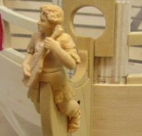
Thistle17 Posted January 10, 2020 Author Share #15 Posted January 10, 2020 I have been ordering ahead even though I have yet to launch head first into this project as I am setting up an artist work area for my wife. We share a common work room and my wife has been patiently waiting for her area for far too long. In any event I just received the full resin set of parts Syren offers. They are astounding in replication and detail. Although his supplier continues to work at improvements these are the best I have seen from any supplier to date. Joe FrankWouts 1 Link to comment Share on other sites More sharing options...
Guest Tim I. Posted April 24, 2020 Share #16 Posted April 24, 2020 Joe, A little late to the party, but following along! - Tim I. Link to comment Share on other sites More sharing options...
Thistle17 Posted May 16, 2021 Author Share #17 Posted May 16, 2021 Seventeen months later, where have i been! I am truly the last pony in this parade. Other projects and family life have just gotten in the way of any progress. I have just finished a major project for someone and now have to clear the decks of two and possibly three model projects (a restoration for someone, a restoration for myself and my Cheerful). But when I see the beauty of what you all are doing I feel a strong urge to "bring her down" and start the process. I need a plan or I will be logging a similar tale a year from now! FrankWouts, scrubbyj427, Rustyj and 1 other 4 Link to comment Share on other sites More sharing options...
Thistle17 Posted May 22, 2022 Author Share #18 Posted May 22, 2022 (edited) The pressure has finally built to the point where I cannot ignore this model any longer. I took it down to start some of the rudimetary work such as fairing the hull. Although I treated the prior work with respect I did have a number of the mid section uprights crack since last year. I have repaired those but i still find those upper elements quite weak and are sure to break during fairing. One advantage of a late start is one gets to see how others have worked through their encounters. I hitch hiked on Stunt Flyer's method albeit with my own rendition shown below. I was careful not to force any of the bulkhead uprights out of their rest position as I expected they would spring back when the 1/16 X 1/8 strapping was removed later on. If needed I added a suitable scrap to keep them in their natural position. The end result is a pretty strudy upper frame area that should take sanding well. The bow and stern areas will have to be dealt with in a similar manner but the scrap build out will be a bit more elaborate. Edited May 23, 2022 by Thistle17 Dave B, Edwardkenway, Ryland Craze and 6 others 9 Link to comment Share on other sites More sharing options...
Oldsalt1950 Posted May 22, 2022 Share #19 Posted May 22, 2022 Looks good Joe. Being you are currently the last, it will be interesting to see what you incorporate from others, and what you discard, FrankWouts 1 Current Build: Fair American - Model Shipways Awaiting Parts - Rattlesnake On the Shelf - English Pinnace 18Th Century Longboat I stand firmly against piracy! Link to comment Share on other sites More sharing options...
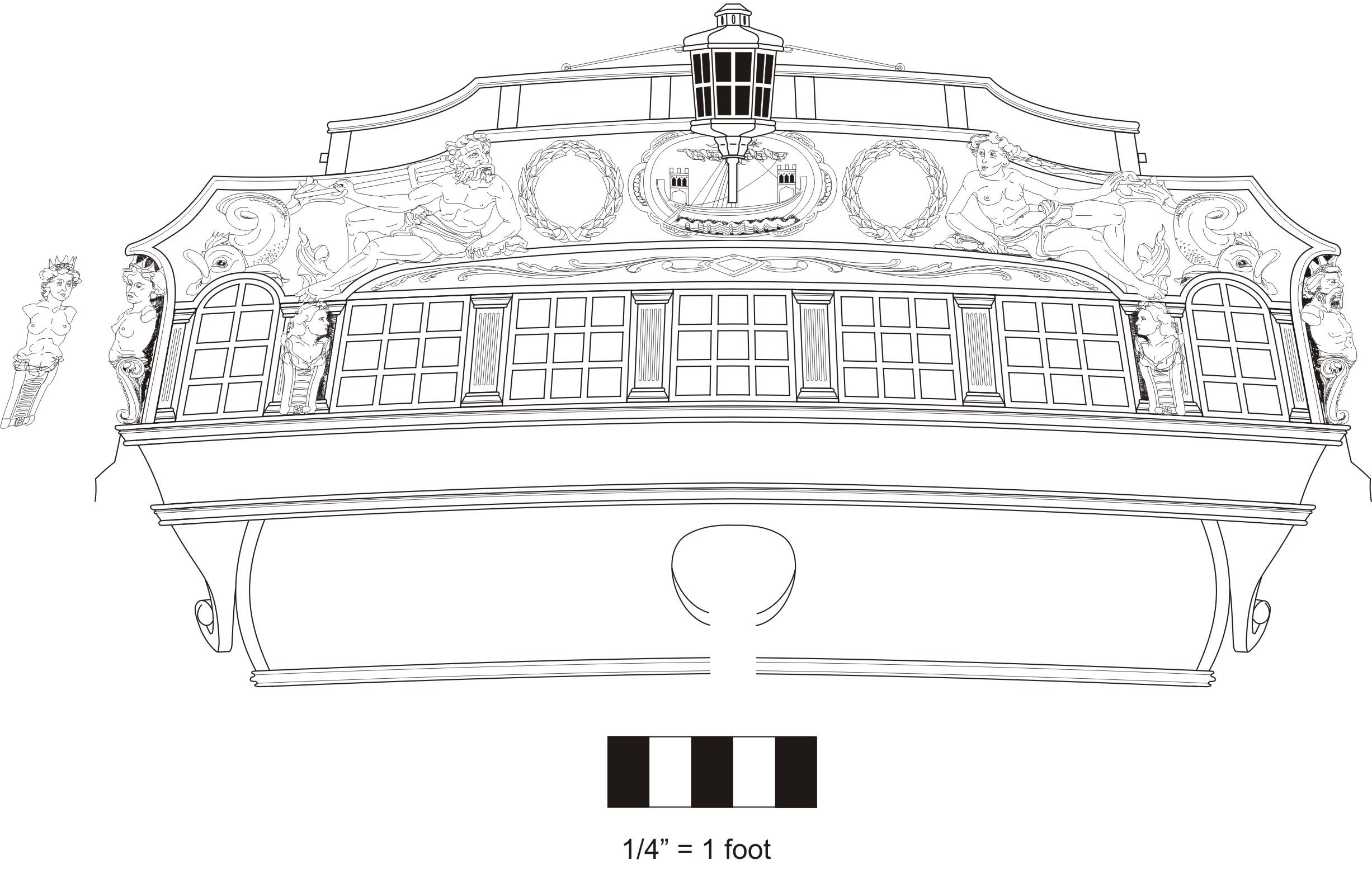
Thistle17 Posted May 28, 2022 Author Share #20 Posted May 28, 2022 Slow at times wins the race as they say. This build is not a contest save with myself to execute this model with the best ideas of others who have traveled before me. I was looking at sheet 3 of the plans last eve and came up with at least 2 questions at this time. 1. The simulated rabbet stops at bulkhead 21. I was trying to envision how the planking would transition to the stern given the rabbett absence. Can anyone recall how that worked? 2. I observe that the gunports on many of the bulkheads appear to have a piece of material "let" into the face that forms the vertical of a gunport. Is that really the case? I do notice that my model ply is pretty rough on the surface so is that the reason the drawing is so? Joe FrankWouts 1 Link to comment Share on other sites More sharing options...
Gregory Posted May 28, 2022 Share #21 Posted May 28, 2022 If I may, I seem to remember Chuck discussing this way back when. Not sure if it is Bulkhead 21, but here is the mention. Ryland Craze and FrankWouts 2 Luck is just another word for good preparation. —MICHAEL ROSE Current builds: Rattlesnake (Scratch From MS Plans On Hold: HMS Resolution ( AKA Ferrett ) In the Gallery: Yacht Mary, Gretel, French Cannon Link to comment Share on other sites More sharing options...
Thistle17 Posted June 17, 2022 Author Share #22 Posted June 17, 2022 As so many of you recount, fairing the bulkheads is such a tedious and for me a boring job! To break the monotny I took a stab at the transom. After sanding and trial fitting I was not pleased with the transom frame member alignment and spacing. There are so many ways to get this wrong even with the care and deliberate bulkhead alignment of #28 and #29 that I took. I clamped the transom facade to the frames and was not surprised to find them out of alignment. One way I thought of to aid in truing up the transom uprights is to copy the drawing of the transom on vellum and attach it to a frame (at the proper height and angle) that I can lay up against the transom and work on the alignment of the members i.e. the slots in the bulkheads. I perceive this will be a tricky method. So to those who have gone before me can you offer some idea(s) of how to go about this critical stage? Joe Chuck, FrankWouts, Rustyj and 1 other 4 Link to comment Share on other sites More sharing options...
Chuck Posted June 17, 2022 Share #23 Posted June 17, 2022 Your care and attention at the stern will pay off in dividends later. You will be rewarded for getting it right. FrankWouts 1 Chuck Passaro - MSW Admin Sloop Speedwell - POF scratch Block Island Boat - POF scratch HMS Winchelsea - POB scratch build HM Cutter Cheerful - POB scratch build Royal Barge - POF scratch Medway Longboat- POF Scratch SYREN SHIP MODEL COMPANY Link to comment Share on other sites More sharing options...
FrankWouts Posted June 18, 2022 Share #24 Posted June 18, 2022 Hi Joe, That looks really great! It's great to look, read and learn in this build group I think. Though you might be much more experienced than me ofcourse. I'm slow as well with little build time per week due to work and family obligations (three daughters)... Frank. Current builds on MSW: HMS Winchelsea 1:48: Prior builds on MSW: None Link to comment Share on other sites More sharing options...
Thistle17 Posted June 18, 2022 Author Share #25 Posted June 18, 2022 Frank I am past the child rearing and career pursuit but I still remember those times. Family was always first. I used to steal away after the house was quite at night and try to work on models for a time. It was not the best time for me to do so. The joy in retirement is there is indeed more time but not as much as one would think. Life for us all has changed. All things equal we are more active and involved than our parents. I may get in at most 2 hours a day during the fair months but no more. And given the standards set by the most accomplished modelers of this community I will either halt my work if running aground until I can find a way to resolve an issue. I actually find the problem solving enjoyable. Such as last night I think I came up with a way to solve the transom alignment problem that will work for me. I will experiment with it and post my results. Joe Ryland Craze and FrankWouts 2 Link to comment Share on other sites More sharing options...
scrubbyj427 Posted June 18, 2022 Share #26 Posted June 18, 2022 Joe, if I remember right the transom uprights are actually not as intimidating as they look. If you follow the plans and measure twice and cut once you should line up pretty well on the two outer frames, also the filler pieces in between for the windows are a significant help. Your fore and aft frames will give you your transom frame angles, this is found in the framing plan. if the frames are placed correctly they form the required curve pretty well, once the fillers are in place then the angle can be established by the framing that attaches to the bulkheads. I spent a lot of time on mine and was quite happy with the results, however I did find a small error but it did not affect my model very much in the end. Looking forward to your updates. Rustyj and FrankWouts 2 Current Builds: HMS Winchelsea 1764 1:48 - 5th rate 32 gun frigate (on hold for now) HMS Portland 1770 Prototype 1:48 - 4th rate 50 gun ship Link to comment Share on other sites More sharing options...
Thistle17 Posted June 20, 2022 Author Share #27 Posted June 20, 2022 (edited) Thanks scrubbyj427. It seems to be a buzzing in my head that won't go away and after thinking about it that is the direction I am heading in (I think at this point) with a jig I had built some time ago which I will adapt for the solution. I am sure people are asking themselves "why is he making this so complicated". The simple answer is it is in my DNA. I used to build homes while I worked for Habitat for Humanity. It was imparative that the foundation diagonals were never more than 1/4" off square. And then that error was made up by the foundation top plates. I carry that sense of things in my cabinetry and furniture building as well. If not, one was always be making up for it for much of the rest of the build. If my method works I will soon share it. Joe Edited June 20, 2022 by Thistle17 Rustyj, Oldsalt1950, scrubbyj427 and 1 other 4 Link to comment Share on other sites More sharing options...
FrankWouts Posted June 21, 2022 Share #28 Posted June 21, 2022 Hi Joe, When you inspect my build log on the transom you'll find I had to do some acrobacy with clamps and long strips to keep the right position on the middle two transom frames to get it right and get that gentle curve in the transom... It came out fine in the end, so if I can do it as a beginner, I'm sure you'll do a very fine job. Frank. Current builds on MSW: HMS Winchelsea 1:48: Prior builds on MSW: None Link to comment Share on other sites More sharing options...
Thistle17 Posted June 21, 2022 Author Share #29 Posted June 21, 2022 Thanks for sticking with me on this. After reviewing your posts on your build and studying the process from #101 on it seems so clear now. No need for an elaborate jig. I am so thankful for your help. Joe FrankWouts 1 Link to comment Share on other sites More sharing options...
Thistle17 Posted June 25, 2022 Author Share #30 Posted June 25, 2022 Back to fairing the hull after my stumbles with the transom frame(s) alignment. I went back to concentrating on the bow bulkheads and fillers. I find this area particularily fussy to work as one is trying to shape the bow mostly through an itterative trial fit process. The battens come in handy for this stage so they must not be neglected in the shaping effort. Observing how the batten lays against the fillers and the first two bulkheads is always a clue to the trueness of shaping. To make things just a bit more complicated the 'W' bulkhead has a mild serpentine curve at its base so that the fillers have to mimic that ever so slightly. To give myself a better chance that all will come out in the end I do not glue the fillers (BF 1 - 3) in as they are so awkward to shape whilst on the model. I start with the bulkhead shaping first ( W and U ). I shape them closely to thier prpoper bevel. In preparation for the next step. I glue fillers, BF 3 & 2 together making sure they align correctly. I then clamp that assembly to the strong back and trace the bottom and rear face of the assembly against the bevel edge of bulkhead 'W". Iteratively I sand via a Dremel with a fine drum sander attached until I get close to the desired surface contours. The process is repeated until I feel I have achieved the desired shaping. I compare my results to some of the helpful photos of Chuck's build as shown in the attachment. In that photo you may notice that I drew in a contour line on the fillers just to get an idea of the shaping trajectory. Ultimately the assembled elements are finished sanded with blocked up linear sanding. This next step is something I learned the hard way in planking Cheerful. On the semi finished starboard filler on the right I drew perpendicular lines as replication markers for its port mate. On the starboard element I drew in a similar contour line as shown on the photo. Using the perpendicular intersects of the starboard side I marked off the port side and drew in the contour shape with a french curve. This produces a very symmetrical bow framing for planking. Now the photo fillers appear a bit wider at the waist area. So as a sanity check I measured Chuck's photo dimensions of the photo filler waist to the distance of bulkhead 'W" from the strong back to its tapered edge and compared it to my contoured filler. I came up with a simple ratio of filler waist width to bulkhead waist width. They turn out to be almost dead on. I am thinking that the appearance difference is the angle and optics of the photo taken. At this point I am second guessing myself and if I am not happy with the results I can always make more fillers and restart the process!!!!!!!!! Joe FrankWouts, rafine, Rustyj and 4 others 7 Link to comment Share on other sites More sharing options...


Recommended Posts