glbarlow Posted July 1, 2022 Share #31 Posted July 1, 2022 (edited) The bow fillers are useful and worth the time. I’m almost done planking and don’t regret adding them, though I took the simpler approach of using balsa. I also duplicated the curved fames above the deck and the bow and added a second set. I noted later Chuck adds filler for the anchor rope hole, adding them now gave me planking support above deck level. As was mentioned the transom frames provide the needed curve by their alignment in the bulkhead slots. I too spent a lot of time working to get them right. Like the fairing every thing done right at this phase pays dividends. Don’t forget the have fun part😊 Edited July 2, 2022 by glbarlow FrankWouts, Ryland Craze, JpR62 and 3 others 6 Regards, Glenn Current Build: HMS Winchelsea Completed Builds: HM Flirt (paused) HM Cutter Cheerful, Lady Nelson, Amati HMS Vanguard, HMS Pegasus, Fair American, HM Granado, HM Pickle, AVS, Pride of Baltimore, Bluenose Link to comment Share on other sites More sharing options...
Thistle17 Posted July 7, 2022 Author Share #32 Posted July 7, 2022 Good advice Glen. I was playing around once again with the transom framing alignment. It is coming along but I came upon something I wonder if people can enlighten me on. I cleaned up the transom fillers and dry fitted and clamped them in place save the outer ones port and starboard. I was a bit surpirsed to find they were a bit too fat. Certainly way to fat to be tweaked. I would say they were 3/32 inch too wide. I laid them on the drawing and found that they are too wide there as well by the same amount. The drawing shows vertical lines on the pieces. Now they could be trim lines. Has anyone had to trim these per the drawing?Have I missed something here? Joe FrankWouts 1 Link to comment Share on other sites More sharing options...
Chuck Posted July 7, 2022 Share #33 Posted July 7, 2022 The sides should be beveled because the stern is curved when viewing it from above. Therefore the fillers are a bit wide until you sand and bevel the sides so they are angled correctly. It is explained in the monograph chapter. FrankWouts and Ryland Craze 2 Chuck Passaro - MSW Admin Sloop Speedwell - POF scratch Block Island Boat - POF scratch HMS Winchelsea - POB scratch build HM Cutter Cheerful - POB scratch build Royal Barge - POF scratch Medway Longboat- POF Scratch SYREN SHIP MODEL COMPANY Link to comment Share on other sites More sharing options...
glbarlow Posted July 7, 2022 Share #34 Posted July 7, 2022 As Chuck notes they require more than tweaking. They form the curve of the stern. Ultimately. In addition to the monograph I’m sure other logs will show the amount of shaping required. FrankWouts 1 Regards, Glenn Current Build: HMS Winchelsea Completed Builds: HM Flirt (paused) HM Cutter Cheerful, Lady Nelson, Amati HMS Vanguard, HMS Pegasus, Fair American, HM Granado, HM Pickle, AVS, Pride of Baltimore, Bluenose Link to comment Share on other sites More sharing options...
Thistle17 Posted July 9, 2022 Author Share #35 Posted July 9, 2022 (edited) Hmmm! I didn't read the monograph thoroughly enough or should i say I did not spend enough time on line where at times more detail can be found. Of course that explains it. Another lesson in more deliberate execution. Not an excuse but at this time I can only spend an hour at best at this and the on again, off again approach does not lend itself to the build. Thank you. Joe Edited July 10, 2022 by Thistle17 glbarlow and FrankWouts 2 Link to comment Share on other sites More sharing options...
Thistle17 Posted July 13, 2022 Author Share #36 Posted July 13, 2022 As I continue the fairing of the hull I spent some time on the bow on the starbaord side and was pleasantly surprised at how it turned out. Methodology was the key for me and the batten trials has served me well. I did extend my bow filler layout method to the port side in the following manner. Before I permantly glued in the starbaord elements I ensured that the taper on both the exposed and backside profile of the port side matched the starboard elements. I then extended the perpendiculars I had inscribed on the starbaord topside element to bulkhead 'W' on the port side. Then using the ;story pole' shown clamped to the strabaord side I marked the taper that would 'dial me in' on port side and made the tick marks shown. In theory this will give me a near identical bow geometry to plank. To my way of thinking this simple method nudges me away from the 'eye balling' I have done in the past that has not always turned out for me. Joe Ryland Craze, scrubbyj427, FrankWouts and 3 others 6 Link to comment Share on other sites More sharing options...
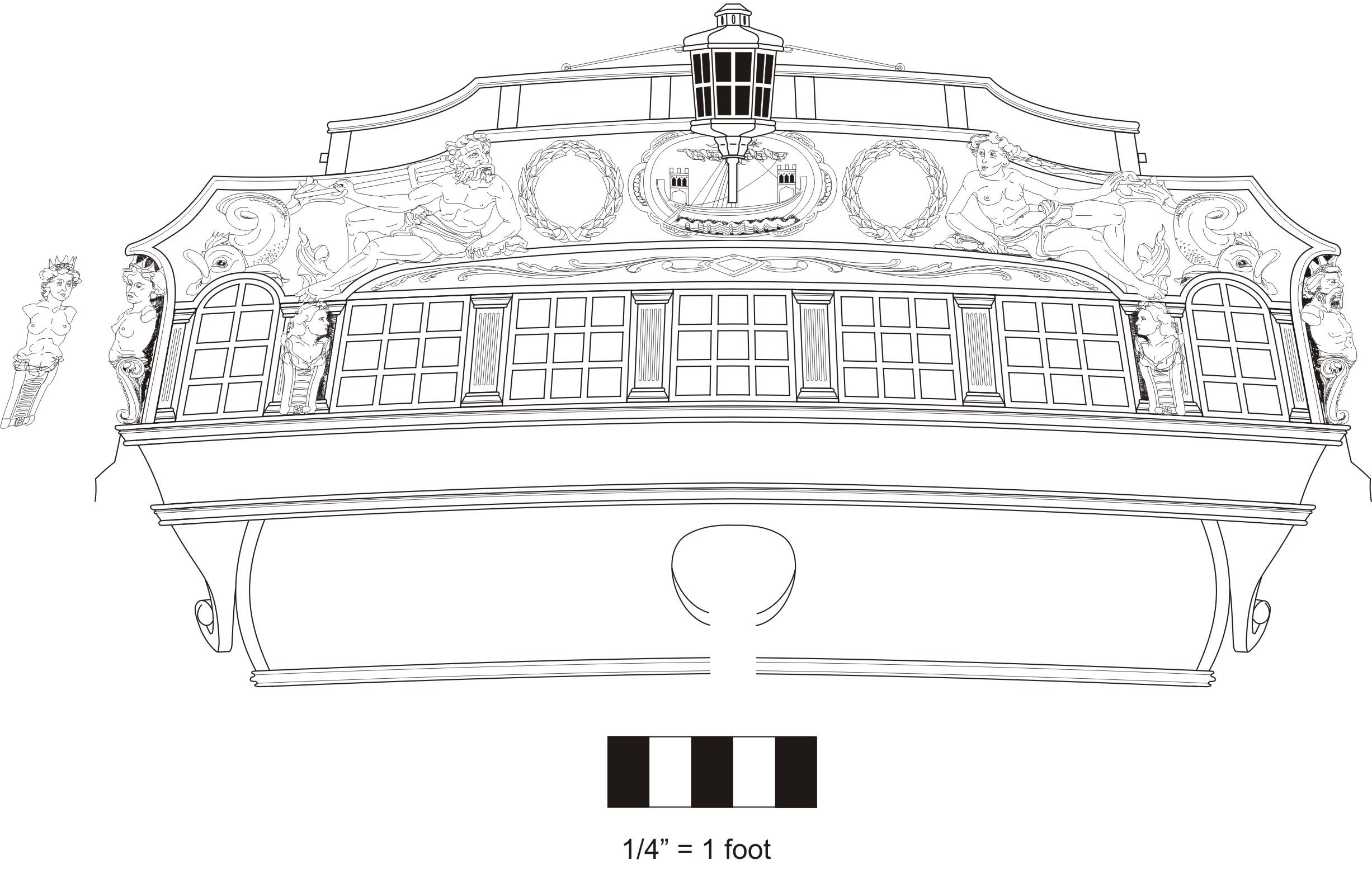
Thistle17 Posted July 13, 2022 Author Share #37 Posted July 13, 2022 (edited) Let me lead in with the following statement before I get into the methodology I have adopted for the stern framing. " In no way am I making any disparaging comments as to the fidelity of the Syren kit parts in my comments herein. I have always found the parts to be well designed and manufactured." Having said that I think many of you might agree that the Winchelsea transom is a bit tricky to assemble and fit correctly. Simply put, it takes quite a bit of care and trial fitting to get it to come out correctly. Not withstanding it all has to take place in mid air! Well it was a bit more of a struggle for me under my circumstances. The problem is unique to my "framing construction" and would not affect others. I only share it for some of you that may be having trouble with "in air" assembly. After a number of attempts to fit the transom frames and fillers in place while all elements were stepwise fit together on the frame. I had to abandon that approach. Before I get further into it I should also say that sanding, chiseling and filing the stern frame slots on #28 and #29 bulkhead resulted in some loose fitting slots. That made the "in air" assembly yet more awkward. So I resorted to an "on the bench" approach. I copied and cut out the stern layout drawing on page 1 of the drawing set. I began with stern frame(s) 'A" and the associated filler for these frames and overlayed them on the drawing cutout. There is no filler tapering required on the filler but to have the frames correctly align I did have to trim the mid filler a bit. Now before going on one has to realize that this is a 2D drawing of a slightly curved transom and has not been adjusted for the concave effects ( I believe this, as the "port holes" in the frieze or the transom covering line up quite well). Successively I am working my way outward and at each step checking by fitting on the stern and with the transom cutout. Note in the picture that the port side filler has yet to be trimmed to fit. I have my fingers crossed that all will come out in the end. Else I may have to repurchase some parts. That will be humbling! Joe Edited July 13, 2022 by Thistle17 Ryland Craze, FrankWouts, westwood and 1 other 4 Link to comment Share on other sites More sharing options...
glbarlow Posted July 13, 2022 Share #38 Posted July 13, 2022 Your precision will pay dividends later. The hull is so big that small errors in geometry are magnified, very thorough approach to keeping that from happening. Surprisingly for me I found the fairing (and later planking) between bulkheads S and U a bigger challenge than what I would have guessed would have been U and W. Getting the correct angle/bevel is key. Ryland Craze and FrankWouts 2 Regards, Glenn Current Build: HMS Winchelsea Completed Builds: HM Flirt (paused) HM Cutter Cheerful, Lady Nelson, Amati HMS Vanguard, HMS Pegasus, Fair American, HM Granado, HM Pickle, AVS, Pride of Baltimore, Bluenose Link to comment Share on other sites More sharing options...
glbarlow Posted July 13, 2022 Share #39 Posted July 13, 2022 6 minutes ago, Thistle17 said: this is a 2D drawing of a slightly curved transom As I'm sure you noted the transom is curved, the outer frames are closer to the hull than the two middle ones, and that you'll be able to account for that curve once its "in air" on the frame. The bottom outside of those doubled up outer frames get carved quite a bit to follow the curve of the wales. When you get to that point I found a cutout of the transom frieze a good tool to match up that curve with the wales and the frieze. The frieze design allows a little room to be small, but no room to be big on that shaping. FrankWouts 1 Regards, Glenn Current Build: HMS Winchelsea Completed Builds: HM Flirt (paused) HM Cutter Cheerful, Lady Nelson, Amati HMS Vanguard, HMS Pegasus, Fair American, HM Granado, HM Pickle, AVS, Pride of Baltimore, Bluenose Link to comment Share on other sites More sharing options...
Thistle17 Posted July 13, 2022 Author Share #40 Posted July 13, 2022 (edited) Thanks Glen for that perspective. I did wonder about how the effects of trimming to fit was going to turn out in the end, Your input gives me the caution I need to hear. Interesting comment on the U and W bulkheads. I will watch that as well, Joe Edited July 13, 2022 by Thistle17 FrankWouts 1 Link to comment Share on other sites More sharing options...
Chuck Posted July 13, 2022 Share #41 Posted July 13, 2022 What you are doing seems like it would be great if the transom was flat. But it isnt. So I am not to optimistic. I am not at all sure how you will fit that onto the model properly and establish the proper curves. But we shall see... FrankWouts 1 Chuck Passaro - MSW Admin Sloop Speedwell - POF scratch Block Island Boat - POF scratch HMS Winchelsea - POB scratch build HM Cutter Cheerful - POB scratch build Royal Barge - POF scratch Medway Longboat- POF Scratch SYREN SHIP MODEL COMPANY Link to comment Share on other sites More sharing options...
glbarlow Posted July 13, 2022 Share #42 Posted July 13, 2022 The best alignment tool is that pattern cut out of the plans with everything cut but the frames, then double-side tape to middle two and use that to space the frames. then the window sills which in addition to length have a beveled angle to sort out. It’s a fun challenge. FrankWouts and Thistle17 2 Regards, Glenn Current Build: HMS Winchelsea Completed Builds: HM Flirt (paused) HM Cutter Cheerful, Lady Nelson, Amati HMS Vanguard, HMS Pegasus, Fair American, HM Granado, HM Pickle, AVS, Pride of Baltimore, Bluenose Link to comment Share on other sites More sharing options...
Thistle17 Posted July 13, 2022 Author Share #43 Posted July 13, 2022 Chuck I understand your doubt. I share it. I did forget to mention that I am tapering the upper stern frame fillers as the on line instructions relate and I am using the guides (1 through 5) to help in the contouring. As I proceed I am taking the partial assembly to the model and testing the fit. So far with one of the 'B' frames correcctly postioned it fits and fits comfortably. As we have discussed my start up has been unconventional and I am paying for that. It was a hard lesson learned that will not be repeated. My escape will have to be some level of do over if it is a disaster. Joe FrankWouts, glbarlow, Ryland Craze and 1 other 4 Link to comment Share on other sites More sharing options...
Thistle17 Posted July 14, 2022 Author Share #44 Posted July 14, 2022 (edited) "DON'T TRY THIS AT HOME!". As one might have guessed my idea of assenbly of the transom in the manner I described while not a disaster was not a complete success. It actually fit the bulkhead slots but as I moved outward from the mid transom frames, especially the 'C' transom frames, it became an assembly in tension. So with 'hat in hand' I reordered Chapter 1 parts again and will start the process over. I have found this segement quite a challenge as there are so many ways that this can go wrong. Am I the only one who has tripped up on this? Joe Edited July 15, 2022 by Thistle17 FrankWouts and glbarlow 2 Link to comment Share on other sites More sharing options...
Chuck Posted July 14, 2022 Share #45 Posted July 14, 2022 Its a slow process. Just keep your templates on hand as you assemble the stern frames and fillers. You could in fact just assemble two frames at a time and then the fillers....working your way out to the sides from the center. That may be easier for you. glbarlow and FrankWouts 2 Chuck Passaro - MSW Admin Sloop Speedwell - POF scratch Block Island Boat - POF scratch HMS Winchelsea - POB scratch build HM Cutter Cheerful - POB scratch build Royal Barge - POF scratch Medway Longboat- POF Scratch SYREN SHIP MODEL COMPANY Link to comment Share on other sites More sharing options...
glbarlow Posted July 14, 2022 Share #46 Posted July 14, 2022 It was a challenge for sure, but as Chuck says a slow process from the center out. Sorry you have to restart with the frames. I still vividly remember my Cheerful frame, nearly done, falling to the floor and shattering. That hurt, starting over is all I could do. FrankWouts 1 Regards, Glenn Current Build: HMS Winchelsea Completed Builds: HM Flirt (paused) HM Cutter Cheerful, Lady Nelson, Amati HMS Vanguard, HMS Pegasus, Fair American, HM Granado, HM Pickle, AVS, Pride of Baltimore, Bluenose Link to comment Share on other sites More sharing options...
Edwardkenway Posted July 14, 2022 Share #47 Posted July 14, 2022 It may help to cut a jig with the curve of the stern and clamp it at the top of the frames whilst in position, I did this after fitting the fillers with white glue, getting the frames sitting near as dammit, then tweaking them as the white glue allowed some movement. FrankWouts 1 Current builds; Henry Ramey Upcher 1:25 Providence whaleboat- 1:25 HMS Winchelsea 1764 1:48 Completed: HM Cutter Sherbourne- 1:64- finished Triton cross section scratch- 1:60 - finished Non ship: SBD-3 Dauntless 1:48 Hasegawa -FINISHED Link to comment Share on other sites More sharing options...
Thistle17 Posted July 15, 2022 Author Share #48 Posted July 15, 2022 Thank you all for your ideas and thoughts. I intend to employ them in the next round. I ordered the kit parts this AM and have patterns cut for potential replacement bulkheads should I need to go that far. I saw a method on the Tally Ho restoration (YouTube) involving the precise layout of critical opening cutouts of covering boards on her deck that might be something worth trying out as a jig. So Edward we will see. Joe Edwardkenway, FrankWouts and Ryland Craze 3 Link to comment Share on other sites More sharing options...
Trussben Posted July 15, 2022 Share #49 Posted July 15, 2022 Look at and use the plans to place those stern frames correctly, all the dimensions and angles can be taken right off them to do the job correctly. i.e the dimension from the level of the keel to the top of the frame height is one you can use, also the distance from one of the bulkhead top frames back to those stern frames is another. Its all right there. scrubbyj427 and FrankWouts 2 Current builds: HMS Pegasus TFFM. HMS Winchelsea. Completed builds: ECHO cross section.18th C Longboat.QA Barge. Medway Longboat. Link to comment Share on other sites More sharing options...
Thistle17 Posted July 23, 2022 Author Share #50 Posted July 23, 2022 (edited) I believe I have reached a milestone in that I have been able to fit all the stern frames correctly and glue in most of them (save the 'C' frames). I have used just about everyones suggestions along the way to do so. Photo(s) to follow. The reason I have not glued in the 'C' frames is that thinking ahead to the quarter galley, fill pieces that will be glued to the inside of the transom element, I am a bit hesitant without asking the following: "Knowing that the planking is 3/64" the galley fill piece edge has to butt up aginst the planking (I understand I have to taper that edge carfefully for a good fit against the hull). So I assume that one needs to account for that 3/64" plus a TBD amount so the filler creates a relatively even lip for the galley rear window. Now the galley filler inside stile is 3/32". That tells me I have to remove just about 3/64" from that stile. Am I correct?" Joe Edited July 23, 2022 by Thistle17 FrankWouts 1 Link to comment Share on other sites More sharing options...
Chuck Posted July 23, 2022 Share #51 Posted July 23, 2022 I am having trouble following your question without pictures. Try just following the monograph. No need to switch it up. Just read ahead if you need to. it is all covered. Finish up the stern as indicated. I believe you are being too cautious and may be overthinking things a bit. No need to develop a new method as you can see by the many build logs....it all worked out wonderfully. Remember the first time you tried to develop a new approach with the stern? Dont be afraid to finish thing up when its stated to do so. As you may be screwing the pooch down the road. There is usually a reason why I created the order and approach back at the stern and it was to hopefully avoid issues later on. But show some pictures and lets see what you are referring too. Just use the template showing the stern frames and if yours line up you are good to go. Then fair them to the dotted line or even a bit further as shown on the plans... Chuck scrubbyj427, FrankWouts, glbarlow and 1 other 4 Chuck Passaro - MSW Admin Sloop Speedwell - POF scratch Block Island Boat - POF scratch HMS Winchelsea - POB scratch build HM Cutter Cheerful - POB scratch build Royal Barge - POF scratch Medway Longboat- POF Scratch SYREN SHIP MODEL COMPANY Link to comment Share on other sites More sharing options...
Thistle17 Posted July 23, 2022 Author Share #52 Posted July 23, 2022 Thanks Chuck. It seems to me I am loosing some concentration in addition to being too cautious and over thinking things as you say. Believe me I am reading the monographs, especially yours. I came back to the model after I'd walked away for an hour and figured it out. Of course when I trim (sand) back the 'C' frames they will give me the relief I need and when I bevel and fit the fillers all should come out well. I have come to be so sensitive to the fit of the elements since if not correct it will be a disaster with the construction of the quarter galleys. What I ended up doing to get the transom frames to have the right fit and sit well was to remove bulkhead 29 and replace them with hand made new ones. That cured almost all the problems with frames "'A' and 'B' as they were too sloppy a fit with all my prior tunning. Joe Ryland Craze, glbarlow, FrankWouts and 1 other 4 Link to comment Share on other sites More sharing options...
Thistle17 Posted July 26, 2022 Author Share #53 Posted July 26, 2022 (edited) If at first you fail to succeed try again...and again...and again! After 2 weeks of on again off again fiddling with the transom framing I think I finally arrived. In no small measure the suggestions and even the "boot in the tail" of the 'master' were the incentives to confront my impediments and move forward. As previously mentioned one key element was the replacement of bulkhead #29. I had adjusted the slots so much of the original ones that I lost the ability for the frames to stay put during construction. So I remade them out of some mahogany that I had gotten from a pattern maker. It took a bit of deliberate hand sawing to get them precise but in the end they proved to be the solution to the loose fit problem of the frames. From that point on it was just a matter of hand tuning the stern upper fillers to get the correct curvature of the stern. In retrospect the 'boot in the tail' also got me to reflect on my state of mind during the prior attempts. As cautioned so many times before slow and steady is the ingredient needed on this model. But I might add one needs to have the right frame of mind and concentration is a must. I just didn't have it before. I was so frutrated about a week earlier that I even ordered the Chapter 1 kit again in anticipation of starting over. It turned out it was not needed. While I am at it I would like to comment on the Syren kit. To have the kit manufacturer design, build and create instructions in a progressive manner is not to be taken for granted. When I finished the stern framing construction I pushed back and mused that Chuck must have had me in mind when he produced the kit parts for this section. Who else adds 'spare" parts and template guides as they perceive that some folk will have trouble in this section? So in the end I think I am where I should be on the transom. I do have some upper counter tuning to do but for the most part it all works. The transom covering piece fits nearly perfect. For me the key was to concentrate on getting the stern port distancing precise. Joe Edited July 26, 2022 by Thistle17 FrankWouts, Ryland Craze, scrubbyj427 and 7 others 10 Link to comment Share on other sites More sharing options...
Rustyj Posted July 26, 2022 Share #54 Posted July 26, 2022 That's looking nice Joe. Sometimes you just have to jump in and have at it! Ryland Craze and FrankWouts 2 Rusty "So Long For Now" Current Builds: Speedwell Completed Build Logs: HMS Winchelsea 1/48 Duchess of Kingston USF Confederacy , US Brig Syren , Triton Cross Section , Bomb Vessel Cross Section, Cutter Cheerful, Queen Anne Barge, Medway Longboat Completed Build Gallery: Brig Syren , 1870 Mississippi Riverboat , 1949 Chris-Craft 19' Runabout Link to comment Share on other sites More sharing options...
scrubbyj427 Posted July 27, 2022 Share #55 Posted July 27, 2022 Good work Joe, looks just as it should. Some advice for fairing the frames, take the drawing Chuck posted in post #51 and cut it out and glue it lightly to the frames to double check and also for fairing the two outer frames. Worked well for me and a little bit of alcohol will take it right off with minimal mess. JJ FrankWouts and Chuck 2 Current Builds: HMS Winchelsea 1764 1:48 - 5th rate 32 gun frigate (on hold for now) HMS Portland 1770 Prototype 1:48 - 4th rate 50 gun ship Link to comment Share on other sites More sharing options...
Chuck Posted July 27, 2022 Share #56 Posted July 27, 2022 Absolutely yes… Chuck FrankWouts 1 Chuck Passaro - MSW Admin Sloop Speedwell - POF scratch Block Island Boat - POF scratch HMS Winchelsea - POB scratch build HM Cutter Cheerful - POB scratch build Royal Barge - POF scratch Medway Longboat- POF Scratch SYREN SHIP MODEL COMPANY Link to comment Share on other sites More sharing options...
glbarlow Posted July 27, 2022 Share #57 Posted July 27, 2022 Well done Joe, you’re on your way now. JJ’s suggestion is a good one, the next challenge is to get a good fit for the lower counter with the fairing on those outer frames. Also a good flow for the transition from counter to stern post with fairing the stern fillers. FrankWouts 1 Regards, Glenn Current Build: HMS Winchelsea Completed Builds: HM Flirt (paused) HM Cutter Cheerful, Lady Nelson, Amati HMS Vanguard, HMS Pegasus, Fair American, HM Granado, HM Pickle, AVS, Pride of Baltimore, Bluenose Link to comment Share on other sites More sharing options...
Thistle17 Posted August 4, 2022 Author Share #58 Posted August 4, 2022 (edited) In the continued fairing process and double checking with template cutouts prior to port hole structural member installation I find I have yet another self inflicted "wound"! I thought I heeded the warning regarding getting the transom postioned correctly as a major factor to get the quarter galleys to come out correctly. But I found the transom angle incorrect after building the simple angle guage. I judged it was not "tweakable". In thinking back I had used my adjustable digital angle guage prior and I can only speculate that the set angle changed from setup. To my dismay I found the transom angle too far off when compaerd to the guage shown. I can trace back some of the creep to my early attempts of fiddling with bulkhead #27 slot depth. It was not much but just enough to give me a cant too sharp to the vertical. Progress came to a scheering halt last eve. This morning I realized there was no opportunity to finesse the error. So off came the transom framing againt bulkhead #29! Now I am faced with the task of how I am to fix this problem. So with Jimmy Buffet's lyric ringing in my head ("Some people claim it's a woman to blame. But I know it's my own damn fault") I have looked at alternatives. None seem to pop at the moment. 1. Start all over again from the skeleton forward. Problem I see is that the framing kit is not even offered on the Syren web site at this time 2. Hat in hand go back and buy Chapter #1 kit for the 3rd time (I just sent it back and got a refund). It includes all the transom parts. How can I do that???? 3. Remake bulkhead #27 through #29 and transom components by hand. Cut out those bulkheads and start again. All need to be cut extremely accurately and identically, especially in the slot areas. So I will let this "cook" for a day or two and proceed. Maybe after sipping a couple of those margaritas it will come to me. Joe Edited August 4, 2022 by Thistle17 FrankWouts, ccoyle and Edwardkenway 3 Link to comment Share on other sites More sharing options...
glbarlow Posted August 4, 2022 Share #59 Posted August 4, 2022 I used a by frame cutout of the plans for both the stern from the rear and the gallery framing from the side rather than trust gauge placements. At this point I’d go option 2 provided you can clear those slots. I think there is some room for margin of error in elements of the build, maybe take a moment and consider how others managed. I know I have a hard time recognizing I am not perfect much to my surprise. 😊 FrankWouts and Ryland Craze 2 Regards, Glenn Current Build: HMS Winchelsea Completed Builds: HM Flirt (paused) HM Cutter Cheerful, Lady Nelson, Amati HMS Vanguard, HMS Pegasus, Fair American, HM Granado, HM Pickle, AVS, Pride of Baltimore, Bluenose Link to comment Share on other sites More sharing options...
Thistle17 Posted August 4, 2022 Author Share #60 Posted August 4, 2022 Glenn I am of your thinking. While I pondered the way out I cleared the slots in the existing framing. It took awhile so as not to destroy any semblence of alignment in the current bulkheads. I also had made some mahogany inserts, that I never used in the first go around, that fit exactlly between bulkheads #27 and #28. They could give me more glue area for the frames. (As an aside I bought through Lee Valley their flushing cutting Japanese double edge pull saw. That has been a marvelous tool for getting fine accurate cuts such as these without wasting away material unneccessarily.) Having reached this point I pulled out saved AYC plates, of chapter 1, that contained the frame elements. I am going to have a go at fashioning the stern frames from that blank. I have learned to hang onto any blanks for just such a use. I do not have AYC of that thickness but I do have box wood that can be used. So, even without that margarita, thngs seem to be looking brighter at the moment. Joe. FrankWouts and Ryland Craze 2 Link to comment Share on other sites More sharing options...


Recommended Posts