catopower Posted November 4, 2019 Author Share #31 Posted November 4, 2019 The next phase of construction involves mostly the framework of the main cabin area. This is very familiar, having built Woody Joe's Higaki Kaisen kit, but I do miss the interior details of that kit. You could probably make modifications to this Kitamaebune kit, to add the same amount of interior detail, but there is no way to see inside, as the doors and the windows are all just solid pieces. It would take some planning to do it, but I think it would be possible. However, there are other ways to modify the kit to consider. I think I mentioned these earlier, but these ships carried a small boat for loading and unloading cargo, which is a feature not included in either of the Woody Joe bezaisen kits (the sailor's term for Japanese coastal transports). The Kitamaebune also often had cargo piled up high on deck, covered with a heavy straw mat, or they had a peaked roof structure erected over the open deck area to shelter cargo. The boat and the deck structure are still items to consider. For now, I've added a sill to the base of each loading gate and then added the cutout portions of the bulwarks back in to better simulate the gates. You can see the starboard side gate in the next photo. If I didn't add the details, you'd only see a solid wall. One of my favorite parts of the model is the arch across the front of the main cabin. Those little square pieces are tennons on the real ship. On the model, these are little 1mm x 1mm pieces you have to cut and glue into place. This is actually a bit tricky to do unless you have a very sharp, thin blade, as hinoki wood this fine is easy to crush when you cut it. I used a scalpel blade, but a very thin razor blade would probably work best – not the hardware store kind, but the kind you can shave with. In these close-up photos, you can see that many of these are slightly malformed as the edges crushed slightly when I cut them. Finally, I started the rudder assembly, as I will be needing it soon. This is another neat piece of hardware on these ships. Through the "magic" of laser cutting, the main part of the rudder already has he individual plank pieces cut into it. This whole assembly is made up of 11 pieces. Below is a better view of the inboard part of the loading gate. I'll be scoring the piece across the top. On the replica ship I visited, and also on the Higaki Kaisen kit, this piece did not exist. There is a gap between the bulwarks you see here and the external fence you see from the outside of the hull. You can actually look down at the space between the two. I expect that the outer fence flexes somewhat and absorbs the impact of large waves that may strike the side of the ship. Below, you can clearly see this gap on the Hakusan Maru replica ship on Sado Island. A bit of a blurry photo here, but this is a view from the staircase up into the ship, passing through the starboard side loading gate. You can see the gate on the opposite side, still in place. Also, that bit of lattice work leaning against the far side is the removable section of the loading gate we're coming through here. All the wooden railing here is just for public safety. Note the slots in the bottom of the photo where that lattice work fence fits into. Landrotten Highlander, JpR62, J11 and 14 others 17 Quote Clare Hess He's a -> "HE" Link to comment Share on other sites More sharing options...
druxey Posted November 4, 2019 Share #32 Posted November 4, 2019 She looks very nice at this point in construction, Clare. The upward sweep to the stern is very elegant. FriedClams, J11, mtaylor and 1 other 4 Quote Be sure to sign up for an epic Nelson/Trafalgar project if you would like to see it made into a TV series http://trafalgar.tv Link to comment Share on other sites More sharing options...
catopower Posted November 24, 2019 Author Share #33 Posted November 24, 2019 (edited) Thank you for the supportive comments, Druxey. The shape of the upward sweeping stern always reminds me of a duck's tail. 🦆 Well, the main cabin gets covered over by deck planking, but not before I get the rudder installed. On this model, the rigging of the rudder is much simplified (like much of the kit). I want the model to stand up to a certain amount of scrutiny. On the Higaki Kaisen model, there is a rope that wraps around the back of the tiller, helping to hold it in the notch in the "great beam" or ōtoko. The rope is doubled and I simply tied it around one of the beams inside the cabin. The rudder's weight is supported by ropes that thread through wooden sheaves on either side of the rudder. The instructions have you hang the ropes from eyelets installed in a beam over the rudder, to be threaded through each side of the sheave, glued, and trimmed off close to the sheave. So, you basically have two rope ends terminating inside the sheave hole. This is expedient, but not a very satisfying rig for a ship modeler. I chose to use the eyelets to tie one end of a length of thread through, run it down through the sheave, back up through the eyelet, back down inside the cabin, and to tie it off to a beam inside the cabin. This much more closely resembles the actual rig. I considered hanging a block in place of the eyelet, but I would have had a hard time fitting the block inside the rudder well at this stage. In any case, the rigging is there and I'm satisfied. In all honesty, it probably doesn't look any better than what the instructions said to do. But, it's more satisfying for this ship modeler. With the rudder in place, I could cover the cabin with the provided pieces of pre-scored planking. I again find the pre-scoring of the planks a bit unsatisfying. But, it does make for a perfect appearance of planks. The biggest downside is that if anything is off in the area of the planking, there's no way to extend the planks to cover a gap. Or, if there is an error in construction and you have to re-make a piece, it may be next to impossible to make a piece that will blend in with the others. So, it's important to check and re-check all assemblies before gluing a piece into place or cutting something. You HAVE to follow directions, or you run the risk of screwing up the build. In the above photo, which I actually took during a test fitting of parts, I noted that the tab at the end of the deck piece is totally visible. That won't do. While it's not very authentic as far as I know, I'll probably just cover that edge with a thin strip of wood, like a covering board. It'll look better than that eyesore tab. The remainder of the planking went fine, though there is a slight gap at the back end of the cabin, next to beam. It's not all that noticeable except, of course, that my eye goes right to it. I will cut a thin strip to drop in there, which will help. The green rubber band you see in the first and last photos helps keep the rudder from lifting up. Later, a rope will fit in its place, as per the kit's instructions. Also, that long slot down the center of the cabin will be covered. This slot is a real part of these ships, though I believe it's continuous and not blocked by that bulkhead piece. This slot allows the mast to be stepped and un-stepped by the crew. The mast was lowered and removed when at anchor, to stabilize the ship. It was then laid across the tops of those three supports. Edited November 24, 2019 by catopower bruce d, RichardG, FriedClams and 11 others 14 Quote Clare Hess He's a -> "HE" Link to comment Share on other sites More sharing options...
druxey Posted November 24, 2019 Share #34 Posted November 24, 2019 I really appreciate your comments about the function of different things, such as that central slot. Very educational! catopower, mtaylor, FriedClams and 1 other 4 Quote Be sure to sign up for an epic Nelson/Trafalgar project if you would like to see it made into a TV series http://trafalgar.tv Link to comment Share on other sites More sharing options...
catopower Posted November 27, 2019 Author Share #35 Posted November 27, 2019 Much appreciated, Druxey! Canute and mtaylor 2 Quote Clare Hess He's a -> "HE" Link to comment Share on other sites More sharing options...
catopower Posted November 28, 2019 Author Share #36 Posted November 28, 2019 (edited) At this point, it's time to look at the copper coverings on the beams and mortises, etc. The Woody Joe kit provides a photo-etched copper sheet, which must be some kind of copper alloy, as it doesn't really tarnish. Below is a photo of the one from the Higaki Kaisen kit, which is very similar. These look fine, but the metal is very bright. As you can see from the photos of the Hakusanmaru, the copper is well tarnished. It's probably very green on the ships on the ocean, but I wanted to simulate simple tarnished copper. I considered using thin copper, which is readily available on the Internet, but thought I'd try something different using a machine that I made use of to solve a recent model dilemma. In that case, I needed to make a very regular decorative pattern. I won't go into a lot of detail on that, but here is a photo of what I was able to accomplish. These are photos of an in-progress model of Edo period Kobaya, or small, fast ship that belong to the Shōgun. The decorations were made using a Silhouette Cameo 3 vinyl cutter – the poor man's laser cutter. The machine is pretty much just a computer plotter (remember those?) with a knife blade in place of a pen. The device connects to any computer, which controls it much like a printer. Included software allowed me to create the designs and to control the cuts. The above photo was taken during unpacking. I got this earlier this year, specifically for solving my decoration issues with that model. Since then, I've found a number of used for it. For the Kitamaebune, I tried out a feature of this unit, which allows me to take a photo of a pattern I want to cut out, and to import it, process it, and create the pattern in permanent, adhesive backed vinyl. The process requires the use of a special cutting mat which is created with registration marks. Unfortunately, I don't have any photos of the intermediate steps. But, the cut vinyl is then applied to the model using a transfer material, which is basically adhesive backed, clear plastic. The cut vinyl will stick to it, allowing you to apply the vinyl to the model, after which the transfer "paper" is peeled off. All those brown colored rectangles and diamonds were cut using the machine. The tip of the stem is also covered in this material and was creating using the PixScan mat and photographing the existing parts. The rectangular and diamond shaped mortise covers, however, were designed by myself. They weren't copies from existing copper. In the below photo, you can see that I've covered the beam ends and added many more detail pieces in vinyl. This includes the black iron parts on the rudder. Like all the rectangular mortise covers, these weren't part of the kit, so I had to draw them up myself. More of this detail yet to come! Clare Edited November 28, 2019 by catopower mtaylor, CapnMac82, GrandpaPhil and 11 others 14 Quote Clare Hess He's a -> "HE" Link to comment Share on other sites More sharing options...
FriedClams Posted November 29, 2019 Share #37 Posted November 29, 2019 Beautiful work you’re doing here Clare. Such an exotic looking vessel to my Western eyes. That is an interesting cutter. I was wondering what the thickness of the vinyl is minus the transfer material. I’m assuming it accepts sheet goods and not materials off rolls. If so, do you feel it would be able to cut .010” or maybe .020” styrene sheet? A very interesting and educational log. I look forward to future updates. Gary bruce d, mtaylor and Canute 3 Quote Current Build Pelican Eastern-Rig Dragger Completed Scratch Builds Rangeley Guide Boat New England Stonington Dragger 1940 Auto Repair Shop Mack FK Shadowbox Link to comment Share on other sites More sharing options...
catopower Posted November 29, 2019 Author Share #38 Posted November 29, 2019 Hi Gary, Thanks for the nice comments. My own cutter is a Cameo Silhouette. The vinyl I use it .003" thick. It can certainly handle thicker, heavier material, but I don't think you could cut styrene with it. A more powerful cutter is the Cricket Maker. It can cut with much more pressure and can cut thin wood. I've seen mention on the Internet of someone using multiple passes using a Cricket Maker to cut 0.040" styrene. So, yes it's definitely be possible with that machine. I specifically bought the Cameo machine to cut vinyl and paper. Also, I chose it because I much preferred the drawing software that comes with it. I tried the Cricket software, but it stores drawings on the Internet, and you need an Internet connection to use it. That's certainly not a problem, but I don't like that I can't just use the machine anywhere with drawings I store on my computer. Clare Canute, FriedClams and mtaylor 3 Quote Clare Hess He's a -> "HE" Link to comment Share on other sites More sharing options...
FriedClams Posted November 29, 2019 Share #39 Posted November 29, 2019 Thanks for the information Clare. These cutters look like they open up some interesting modeling opportunities and I like how you're using yours. All those little accents, the diamonds and rectangles would be a bear to produce manually and uniformly. Maybe I'll take a look at the Cricket Maker. 5 hours ago, catopower said: but I don't like that I can't just use the machine anywhere with drawings I store on my computer. Agree totally. That is strange - sort of makes me suspicious. Keep up the great work and thanks again. Gary mtaylor, catopower and Canute 3 Quote Current Build Pelican Eastern-Rig Dragger Completed Scratch Builds Rangeley Guide Boat New England Stonington Dragger 1940 Auto Repair Shop Mack FK Shadowbox Link to comment Share on other sites More sharing options...
mtaylor Posted November 30, 2019 Share #40 Posted November 30, 2019 It's good you have local storage, Clare. Old saying in IT... store your data on someone else's computer and they own it and can lose it. Canute, catopower, JayCub and 1 other 4 Quote Mark "The shipwright is slow, but the wood is patient." - me Current Build: Past Builds: La Belle Poule 1765 - French Frigate from ANCRE plans - ON HOLD Triton Cross-Section NRG Hallf Hull Planking Kit HMS Sphinx 1775 - Vanguard Models - 1:64 Non-Ship Model: On hold, maybe forever: CH-53 Sikorsky - 1:48 - Revell - Completed Licorne - 1755 from Hahn Plans (Scratch) Version 2.0 (Abandoned) Link to comment Share on other sites More sharing options...
catopower Posted December 2, 2019 Author Share #41 Posted December 2, 2019 Actually, I've read recently that someone was able to cut styrene up to .015" on the same machine I have. Any thicker required him to separate the parts manually with a knife. But, the Cricut Maker can definitely cut thicker. Regarding the software, I went on both manufacturer's sites and downloaded their software for free to try them out to learn how to work with it first. Being on a Mac and not a PC, I was cautious about it. As I said, I preferred the Cameo software. Though both were free downloads, I ended up paying $50 for an upgrade to the Cameo software, primarily to allow me to import files that I could create in Adobe Illustrator, since I already know how to do a lot with that software. As for the uses of the vinyl cutter, this is great for creating vinyl lettering, which one of the members of the Hyde Street Pier Model Shipwrights group in San Francisco introduced us to some time back. One of the members of my ship model club asked me if I could cut his ship's name for the transom on his model, which I did. It can cut pretty amazingly small details, though it is cutting vinyl, which can flex a bit. So, applying the cut vinyl requires a lot of care. I've recently some templates in vinyl, which gave me regularly spaced rectangles, which I used as a guide for cutting mortises on another Japanese wooden boat model I made. Saved me some time and kept me from drawing a lot of pencil marks, which are hard to remove from the soft wood. I've also considered using it to cut masks, so that the final product on the model is just paint, rather than vinyl. Haven't tried that yet, though. Of course, you can cut other material, like paper. And for that, it works very well. I do wish this machine were a bit tougher, though, as I would like to cut thin copper foil. Clare Ryland Craze, Canute, mtaylor and 1 other 4 Quote Clare Hess He's a -> "HE" Link to comment Share on other sites More sharing options...
ccoyle Posted December 2, 2019 Share #42 Posted December 2, 2019 Catching up on your log, Clare. She looks a real treat to this point. FriedClams, mtaylor and Canute 3 Quote Chris Coyle Greer, South Carolina When you have to shoot, shoot. Don't talk. - Tuco Current builds: Brigantine Phoenix, Hawker Hurricane Link to comment Share on other sites More sharing options...
catopower Posted December 2, 2019 Author Share #43 Posted December 2, 2019 (edited) Scratch-built Tenmasen from Paris drawings Something that I tried, but failed to do on my previous Japanese coastal transport, the Higaki kaisen, was to make a Tenmasen, a small lighter that was carried aboard these ships. Since the ships were too large to travel up waterways, they'd anchor close to shore, and this small boat was used to ferry crew and cargo to and from shore. The term Tenmasen (ten-mah-sen), or simply Tenma, seems to be used across Japan to refer to different types of workboats. My 1/72-scale Tenmasen was based on drawings by Paris, made in the late Edo or early Meiji periods. It differs from what I've seen in most Japanese references. It seems a bit simpler. Maybe more functional and a little less elegant than versions I've seen in books or the reproduction I saw on Sado island. I had a time trying to build this as a planked boat at such a small scale, so I broke down and carved the lower hull, then added the beams and upper hull planks and such. There is still some work to do on it, but all the structural work is done now. The boat is interesting in that it is very shallow draft and very wide. It's clear in the drawings, but you don't really realize it until you see it in 3D. Boat Builder Douglas Brooks brought a model of a Tenmasen to the NRG conference at Mystic. It's the upper model in the photo below. That one was made by his teacher, and appears to represent a canal boat, as it was poled, and had no fittings for a sculling oar. The Tenmasen replica I saw on Sado Island, Japan, was very different, and had sawed frames added for strength. It had a pair of Ro, or sculling oars, but had a couple paddles, probably just to aid in manuevering. I find it interesting that at the time Paris made his drawings of this small boat, unlike all the Japanese representations, this boat had 11 oars, and only one of them was a sculling oar. Whereas, all the Japanese representations show boats that are primarily sculled. Some, like the one on Sado, had paddles, but no apparent way to rig them to use as oars. This is something that bothered me a bit when I went to work drawing up and building a model of an Edo period boat from 1803 and earlier. This boat was illustrated in a kind of book used by tax assessors. The boat, called a Tenma-zukuri chabune, or Tenma-style "tea boat", and was one of many illustrated boats that showed no fittings for the use of sculling oars. When I drew up my plans and built my model, it seemed that most of my knowledgeable friends in Japan felt that the illustration was wrong and that it should have fittings for a sculling oar. I'm not one to ignore the only piece of actual historical evidence, but people were insisting that it have the fitting for a sculling oar, so I drew the plans with the fitting, but couldn't bring myself to build the model that way. The photo below shows that 1/20-scale model, mostly finished, but with a few details I've been neglecting. By the way, I made use of the vinyl cutter here to make those nail ends you see on the inside of the hull. I also used it to make templates for cutting those mortises in the rub rails. But, more about this particular model another time. Anyway, the point being that I'm not sure if the use of the sculling oar was as widespread as people believe today. I have yet to find anyone who knows its history of use in Japan, though I think it's widely accepted that it was a technology that was imported from China, where it is called a yuloh. In any case, the Kitamaebune looks like it will be equipped with a tenmasen. Clare Edited December 2, 2019 by catopower JpR62, Canute, GrandpaPhil and 10 others 13 Quote Clare Hess He's a -> "HE" Link to comment Share on other sites More sharing options...
druxey Posted December 2, 2019 Share #44 Posted December 2, 2019 Your vinyl solution looks very good, Clare! mtaylor and Canute 2 Quote Be sure to sign up for an epic Nelson/Trafalgar project if you would like to see it made into a TV series http://trafalgar.tv Link to comment Share on other sites More sharing options...
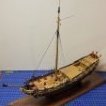
catopower Posted February 10, 2020 Author Share #45 Posted February 10, 2020 (edited) Been a while since my last post! I set the model aside to deal with other things, but also to take a break from all fiddly design work that I'm dealing with now on the Kitamaebune model. Up to now, I've been mostly adding simple rectangular pieces of vinyl. Now, I'm at the stage where I'm having to deal with more unusual shapes. This requires scanning, drawing, adjusting, cutting, testing, and repeating. But, I decided to get back to it, since I'm not far from completion. Added a few more custom pieces at the stern... Attached the tassle-like piece called a sagari, which functions much like a figurehead. Still more custom vinyl pieces to draw up and add to the hull, but I'm close to being done with this phase of construction. Clare Edited February 10, 2020 by catopower druxey, mtaylor, JayCub and 5 others 8 Quote Clare Hess He's a -> "HE" Link to comment Share on other sites More sharing options...
catopower Posted February 10, 2020 Author Share #46 Posted February 10, 2020 Hey, while I'm at it, I might as well litter my own build log with something else I finished up as a quick side project – this is Woody Joe's Nihonbashi Bridge kit. I've had this kit in the stash for about a year. I decided I needed to make something simple over the holidays, so I pulled this one out. It was a really fun and pretty easy build. Would have been easier, except I wanted to add figures. Also, I wanted more realistic looking boats than what was in the kit. So, I scratch built some... I added some small details and I did have fun painting the figures, though I decided to buy some new Vallejo paints for the job. The water is from Woodland Scenics. The cherry blossom trees are made by Woody Joe and included in the kit. Okay, now back to our regular programming! Clare FriedClams, JayCub, ccoyle and 9 others 12 Quote Clare Hess He's a -> "HE" Link to comment Share on other sites More sharing options...
ccoyle Posted February 10, 2020 Share #47 Posted February 10, 2020 Your diorama received a well-deserved post at our FB page. JayCub, EricWilliamMarshall, FriedClams and 3 others 6 Quote Chris Coyle Greer, South Carolina When you have to shoot, shoot. Don't talk. - Tuco Current builds: Brigantine Phoenix, Hawker Hurricane Link to comment Share on other sites More sharing options...
VTHokiEE Posted February 10, 2020 Share #48 Posted February 10, 2020 (edited) What a beautiful diorama; I’ve always wanted to build something like that. Would you recommend it as a first time diorama? If so, is there anything else that I would need aside from the water? Edited February 10, 2020 by VTHokiEE catopower, mtaylor, Canute and 1 other 4 Quote Current Build: HM Sloop Echo 1781 (First Scratch Build) Previous Builds: HM Cutter Alert, Sharpie Schooner, Chesapeake Bay Flattie, Half-Hull (NRG) Link to comment Share on other sites More sharing options...
Tim Murphy Posted February 11, 2020 Share #49 Posted February 11, 2020 Clare, I just restarted by kit. I’m working on it when I am at the Constitution Museum as a volunteer. Your build here has a lot of great details to help me in the build. Thank’s Tim mtaylor, catopower, FriedClams and 1 other 4 Quote Link to comment Share on other sites More sharing options...
catopower Posted February 11, 2020 Author Share #50 Posted February 11, 2020 Thanks Chris! Hope others try out the kit – it's a fun build. VTHokiEE, structurally, it's pretty easy. The kit has some very basic representations of boats, so I made my own. But, besides that, the only thing special was the use of some small figures. You can either get some and paint them, or just buy one or two sets of pre-painted figures. Of course you pay more for them if they're pre-painted, but they seem to look really nice. Also, the figures at 1/150 scale are really tiny to paint. I ended up painting some, but I needed to buy some nicer colors. I probably spent more on the unpainted figures and paints than if I had just purchased a couple sets of pre-painted figures! The water is just Woodland Scenics Realistic Water with a few drops of their Moss Green Water Tint poured over a painted river bottom. You can get the Nihon Bashi Bridge kit from Zootoyz.jp: https://www.japan-wooden-model-kits-zootoyz.shop/contents/en-us/p24828_Nihonbashi-Wooden-Mini-Bridge-Model-by-Woody-JOE.html And the figures here: https://www.japan-wooden-model-kits-zootoyz.shop/contents/en-us/d2045761182_Edo-period-figures-Diorama-products-by-Woody-JOE.html I hope you build it, or one of their other kits. They have a lot of castle and temple kits that would look nice in a diorama format with figures and all. Clare FriedClams, GrandpaPhil, mtaylor and 6 others 9 Quote Clare Hess He's a -> "HE" Link to comment Share on other sites More sharing options...
catopower Posted February 11, 2020 Author Share #51 Posted February 11, 2020 Tim, which kit is it that are you building? Last I recall, you were interested in Woody Joe's Hacchoro. Thanks again for the whaleboat photos. I printed up a plan in the same 1/10 scale as the one in New Bedford, rolled it out at a club meeting, and realized it's GINORMOUS! It would really be a memorable model, but I might need a bigger car to transport it... and a bigger house. But, it's nice to have a big model, so I'm considering moving to yet another odd scale of 1/15. I just wish I could build models at a consistent scale, or even two scales. At minimum, I need to finish one other project first! Clare Canute, FriedClams and mtaylor 3 Quote Clare Hess He's a -> "HE" Link to comment Share on other sites More sharing options...
FriedClams Posted February 12, 2020 Share #52 Posted February 12, 2020 Nice diorama Clare - a charming scene. Good call on the boats. Yours are much more interesting and detailed than those shown on the box photo. Does the diorama get a base or surround? Good to see you back on the Kitamaebune. Gary druxey, catopower, mtaylor and 1 other 4 Quote Current Build Pelican Eastern-Rig Dragger Completed Scratch Builds Rangeley Guide Boat New England Stonington Dragger 1940 Auto Repair Shop Mack FK Shadowbox Link to comment Share on other sites More sharing options...
catopower Posted February 13, 2020 Author Share #53 Posted February 13, 2020 Thanks Gary. The diorama is going inside a small acrylic case with a black acrylic base. The case just arrived yesterday and I'm very happy with it. It was $52 shipped and very nice quality. Nice to be able to put a build into a case so cheaply! Clare mtaylor, Canute and FriedClams 3 Quote Clare Hess He's a -> "HE" Link to comment Share on other sites More sharing options...
catopower Posted February 13, 2020 Author Share #54 Posted February 13, 2020 Here's a last aside. The little Nihonbashi Bridge diorama now has its case. It's a bit on the large side, but it was the closest standard sized case that would fit. I also recently finished a model of a 1-person riverboat from Niigata prefecture that was built by Mr. Nakaichi Nakagawa and Douglas Brooks last Fall. The model is a 1/10-scale model of a Honryou-sen, a type of fishing boat that was also used occasionally as a workboat for carrying gravel. It's a long model, and narrow. With no frames and only one beam, it was a bit of a task to keep it from twisting. There are two ringbolts that I may still add to it, one in the bow plank and one in the transom plank. It was propelled like a canoe, using a paddle. I have to make that too, still. I actually was making two in parallel, but got ahead with this one, so I could get it finished. Clare BobG, Landrotten Highlander, mtaylor and 7 others 10 Quote Clare Hess He's a -> "HE" Link to comment Share on other sites More sharing options...
catopower Posted March 2, 2020 Author Share #55 Posted March 2, 2020 Getting back to the Kitamaebune model, I've finally made significant progress, though it doesn't really show. It's all in the small details – the simulated copper coverings are finally done! This took me a while as I kept thinking I was done. Then, I'd think some more and realize there was some other feature I wanted to add. I'd no sooner finish that, than realize I really should add yet another feature. This cycle has repeated itself many times, but I think it's over now. Kind of like getting sick and you think you're done – but nope... Of course, the end result with the model is a lot nicer imagery! In the images below, the red arrows and circles show newly added detail. The green show added detail that was actually based on kit part that I recreated in vinyl, as well as some small wooden posts I added to the beam at the bow and the end of the tiller. Still a lot of wooden details I need to add. But, this vinyl cutting phase looks like it's finally over, and I can put that equipment away. I'll be adding boat chocks, windlass handles, and will be considering adding the two small auxiliary masts that were often mounted on these ships near the bow. There are also a number of tenon joints that I want to simulate. I'd actually already done a couple, but found they were in the way of finishing the "coppering" detail. EricWilliamMarshall, mtaylor, FriedClams and 10 others 13 Quote Clare Hess He's a -> "HE" Link to comment Share on other sites More sharing options...
druxey Posted March 2, 2020 Share #56 Posted March 2, 2020 Quite spectacular, Clare! FriedClams, mtaylor and Canute 3 Quote Be sure to sign up for an epic Nelson/Trafalgar project if you would like to see it made into a TV series http://trafalgar.tv Link to comment Share on other sites More sharing options...
Kurt Johnson Posted March 3, 2020 Share #57 Posted March 3, 2020 Clare, The Honryou-sen hull really has a very elegant flowing look to it. Kurt mtaylor and Canute 2 Quote Member: Ship Model Society of New Jersey Link to comment Share on other sites More sharing options...
catopower Posted March 4, 2020 Author Share #58 Posted March 4, 2020 Thanks Druxey! You always say the nicest things. Hi Kurt, I agree about the shape of the Honryou-sen. Most of the other boats I've seen of this style of construction are practically double-enders and don't have the nice "flowing look" to them, as you put it. At some point, I'd like to make a couple of them, but they are so simple looking with few details that they wouldn't be all that interesting to look at. Even the Honryou-sen is a bit simple looking, though I have a few small details I need to add to it. Plus, I need to make a kai, or paddle, for it. Clare Canute, mtaylor and BobG 3 Quote Clare Hess He's a -> "HE" Link to comment Share on other sites More sharing options...
catopower Posted March 10, 2020 Author Share #59 Posted March 10, 2020 A quick update on the Kitamaebune model. With the completion of the vinyl "coppering" details, I started thinking about other non-kit details. The next item I decided is pretty straight forward and related to the vinyl "coppering" details. Often times, the coastal transports, known generally as bezaisen, are shown with nail heads in the bulwarks fences. Adding these at this scale may be a mistake, but I've started down the road – No turning back now. I drilled out all the necessary holes which will be plugged with some 22 gauge copper wire. I intend to blacken the wire using liver of sulfur. Holes were drilled out and I started the process of making copper "nails". The heads have to be flat, so I filed the end of the wire and then cut the "nail" off. I glued the finished nails into the holes and pressed them flat against the hull. The process seemed to work okay, though I won't really know how well I will like the results until it's all done. It's slow going, but there aren't really too many to do when you get down to it. In the photo above, the red arrows point to some of the copper nails after they've been place. There's a ways to go, but it's a start. As a side note, I'm going to need to start a build log for a card model that is connected with some new products that are being carried by Ages of Sail. Look for it in coming days. But, I will be pushing forward to finish the Kitamaebune fairly soon. Clare Ekis, FriedClams, Canute and 7 others 10 Quote Clare Hess He's a -> "HE" Link to comment Share on other sites More sharing options...
catopower Posted March 30, 2020 Author Share #60 Posted March 30, 2020 Finished up with those nails and they look okay. Not perfect – I have to work on technique there. But, they'll do. Adding a rope around the sagari, the tassle hanging from the tip of the stem. I wanted this to be a bit decorative, so I found some white linen line and used gouache to color it. So far, this has produced the brightest colors. Main problem right now is that I seemed to have misplace the kit instructions! Not a total loss, as I've built the Higaki Kaisen kit, which is very similar, and I'm at the stage were I'm basically going to rig the mast and sail. That part is pretty much identical to the Higaki Kaisen kit. Also, I have the instructions for that kit, should I need to reference something. Not sure how I'm going to handle the sail. I'd like to add a bow sail – don't know what the Japanese term is for this. Probably an omote no ho, which is the equivalent of "face" or "bow" sail. Have to figure out how to mount that one. Also, I want the bow sail and the main sail to match in terms of material and construction. Since I'm going to have to scratch build the bow sail, I think I'm going to have to do the same with the main sail. Luckily, I just had some sail sewing practice for two other projects, so I'm fairly ready for this one. Only question is how detailed and accurate I'm going to make these sails. The real sails are make up of some 18 narrow vertical panels that are laced together. Several panels make up a group that is more loosely laced to the next group. A total of maybe 4 groups then make up the main sail. This lacing will open up the gap between the panels, spilling air when the wind gusts, making them effectively self reefing. Not sure if I can really reproduce this appearance at this scale. But, I need to try. I found a couple photos that help to illustrated what I mean about the way Japanese sails are made. These were posted last year by member marcjp in Bob Riddoch's Higaki Kaisen build log, but they really help out here. If you look closely, you can see how the vertical panels are separate pieces that are laced together. Note the division of panels at the base of the mast. Anyway, this is what I'm starting to work on now, making sails that reflect or simulate these details. The sails provided in the kit are actually very good, and they have a printed pattern that gives them a bit of this effect. In fact, someone was amazed when they saw the sails on my Higaki Kaisen model, thinking I had sewn them. So, they must look pretty convincing on their own. Clare Canute, Ekis, mtaylor and 6 others 9 Quote Clare Hess He's a -> "HE" Link to comment Share on other sites More sharing options...

Recommended Posts
Join the conversation
You can post now and register later. If you have an account, sign in now to post with your account.