KrisWood Posted July 28, 2021 Author Share #391 Posted July 28, 2021 Note to self, just found these.... https://www.academia.edu/49550751/Rekonstruktion_af_Osebergskibet_Bind_I https://www.academia.edu/49550641/Rekonstruktion_af_Osebergskibet_Bind_II Complete reconstruction plans for every single part of the ship. 😲 mtaylor, Brinkman, AnobiumPunctatum and 2 others 5 Quote Link to comment Share on other sites More sharing options...
Louie da fly Posted July 29, 2021 Share #392 Posted July 29, 2021 That's a nice find, Kris. Steven mtaylor, KrisWood and Cathead 3 Quote It's not really a ship model unless you've bled on it. CURRENT BUILDS Venetian merchant Ship from Basilica of San Marco Golden City - Ballarat paddlewheeler FINISHED Australian couta boat RMS Titanic HMVS Cerberus 11th century Byzantine dromon Winchelsea Nef - Late 13th century Mediaeval ship Henry Grace a Dieu - Rebuild of 1:200 model I started in 1967 https://modelshipworld.com/topic/36379-mistydeefer-by-louie-da-fly-finished-restoration-decor-yacht/#comment-1040663 Mistydeefer - restoration of decor model yacht Link to comment Share on other sites More sharing options...
KrisWood Posted July 31, 2021 Author Share #393 Posted July 31, 2021 Before my last post the other day, I'd been quiet for a long time. Several months ago my laptop died and so I was no longer able to work on my project. Around the same time I had to get a second job to keep up with the bills, so I didn't have time for projects anyway. On the bright side, the second job meant I finally had enough money to buy a new laptop. Reading the two volume reconstruction report by Ms Bischoff has inspired me to get back into my project. Having read the report and reviewed the plans, I see now that I got several things wrong and I'm going to need to start over, this time doing it entirely by the numbers instead of by eye. I've already started on the keel using the new dimensions. It's much easier to plot out the T shape now that I have the numbers for sections I'd been missing before and guessing at by eye, and I can already tell it's not going to be as fragile as it was before. Meanwhile I still have very little time (due to the two jobs and all). Does anyone want to collaborate on plugging in the numbers from the report above into Rhino? mtaylor and AnobiumPunctatum 2 Quote Link to comment Share on other sites More sharing options...
AnobiumPunctatum Posted August 1, 2021 Share #394 Posted August 1, 2021 Thanks for sharing this find. You can be very happy that you can understand what Wiebke writes. I have to use a translator BLACK VIKING and mtaylor 2 Quote Regards Christian Current build: HM Cutter Alert, 1777; HM Sloop Fly, 1776 - 1/36 On the drawing board: English Ship Sloops Fly, 1776, Comet, 1783 and Aetna, 1776; Naval Cutter Alert, 1777 Paused: HMS Triton, 1771 - 1/48 "Have no fear of perfection - you'll never reach it." Salvador Dali Link to comment Share on other sites More sharing options...
KrisWood Posted August 1, 2021 Author Share #395 Posted August 1, 2021 (edited) 13 hours ago, AnobiumPunctatum said: Thanks for sharing this find. You can be very happy that you can understand what Wiebke writes. I have to use a translator I rely entirely upon Google Translate and what little I remember of taking German in highschool (a good portion of the Danish words that Google mistranslates are similar enough to German that I can read them). 😆 Fortunately, this latest report has a glossary of Nordic shipbuilding terms in it that is a bit easier for Google to translate. 🙂 Edited August 1, 2021 by KrisWood mtaylor, AnobiumPunctatum and Cathead 3 Quote Link to comment Share on other sites More sharing options...
KrisWood Posted August 16, 2021 Author Share #396 Posted August 16, 2021 Well, it's back to the drawing board for me. I went to combine the new plans with my existing ones and found that the lines I'd drawn previously. When I tried to add my newly drawn frames with exact measurements I couldn't get them to fit! Apparently when I'd faired the strakes I lost several centimeters of the hull's breadth. The other difficulty I ran into is that the new plans show the frames viewed from the front, but they also include the exact position and angle in top and profile views for each frame. I can draw the frames easily enough in the front view, but how can I project them onto the angled position they end up in? mtaylor 1 Quote Link to comment Share on other sites More sharing options...
Roger Pellett Posted August 16, 2021 Share #397 Posted August 16, 2021 It would be helpful if you could post a picture illustrating your post. Roger Cathead 1 Quote Link to comment Share on other sites More sharing options...
KrisWood Posted August 17, 2021 Author Share #398 Posted August 17, 2021 Hi Roger, I'll post some images when I get to that point. I'm still drawing all the frames because I didn't have good plans to work from for them until now. After that I'll redraw the strakes and re-fair them, and then I'll be ready to work on placing the frames correctly within the hull. mtaylor 1 Quote Link to comment Share on other sites More sharing options...
Louie da fly Posted August 18, 2021 Share #399 Posted August 18, 2021 On 8/17/2021 at 2:15 AM, KrisWood said: I can draw the frames easily enough in the front view, but how can I project them onto the angled position they end up in? Does that mean the frames are angled from the vertical? Like a raked mast? If so, there is a way to do it by "projecting" lines on the paper at right angles to the frame itself. I hope this isn't too confusing. It's a bit hard to explain clearly. Maybe a diagram will help: But if the angling doesn't change frame width, all you really need to do is proportionally adjust the frame heights (for example, if the angled frame needs to be 10% higher than it appears to be from directly front-on (i.e. at right-angles), increase the height of each point of the frame by 10%.) Perhaps you can "stretch" your drawing in some program like "paint" or photoshop. I hope this helps. Steven mtaylor and Cathead 2 Quote It's not really a ship model unless you've bled on it. CURRENT BUILDS Venetian merchant Ship from Basilica of San Marco Golden City - Ballarat paddlewheeler FINISHED Australian couta boat RMS Titanic HMVS Cerberus 11th century Byzantine dromon Winchelsea Nef - Late 13th century Mediaeval ship Henry Grace a Dieu - Rebuild of 1:200 model I started in 1967 https://modelshipworld.com/topic/36379-mistydeefer-by-louie-da-fly-finished-restoration-decor-yacht/#comment-1040663 Mistydeefer - restoration of decor model yacht Link to comment Share on other sites More sharing options...
KrisWood Posted August 18, 2021 Author Share #400 Posted August 18, 2021 (edited) 10 hours ago, Louie da fly said: Does that mean the frames are angled from the vertical? Like a raked mast? If so, there is a way to do it by "projecting" lines on the paper at right angles to the frame itself. I hope this isn't too confusing. It's a bit hard to explain clearly. Maybe a diagram will help: But if the angling doesn't change frame width, all you really need to do is proportionally adjust the frame heights (for example, if the angled frame needs to be 10% higher than it appears to be from directly front-on (i.e. at right-angles), increase the height of each point of the frame by 10%.) Perhaps you can "stretch" your drawing in some program like "paint" or photoshop. I hope this helps. Steven Thank you, Steven! I understand the concept you illustrated, and I've used it in other projects for cant frames, but the frames on Viking ships are a little different. They are angled on two axes rather than one. I'd rather not link images directly from the paper linked above because I don't own the images, so I'll reference the specific pages instead. Here's the link again: https://www.academia.edu/49550641/Rekonstruktion_af_Osebergskibet_Bind_II Plans 12 through 27 depict the frames from the front view. Plans 28a (profile view, starboard on top, port on bottom) and 28b (top view) depict the frames in-situ within the hull. You can see that the frames are not projected straight onto these axes, either. The frame timbers themselves are more angled. The knees are more vertical. In many places the frames are perpendicular to the curves of the strakes rather than to the longitudinal axis. Does that make more sense? In any event my question was more, "how does one accomplish this in Rhino" than "how does one accomplish this on paper". Edited August 18, 2021 by KrisWood corrected the page references Cathead and mtaylor 2 Quote Link to comment Share on other sites More sharing options...
Roger Pellett Posted August 19, 2021 Share #401 Posted August 19, 2021 Sorry, Kris, but when I clicked onto your reference, the site identified the material as “Premium Content,” and I couldn’t open it. I cannot comment on Rhino but probably could draw it on paper if I could visualize the situation. Roger KrisWood and mtaylor 2 Quote Link to comment Share on other sites More sharing options...
AnobiumPunctatum Posted August 19, 2021 Share #402 Posted August 19, 2021 Kris I can only help by converting in 2D because my 3D skills are minimal. If You work in 2D you can draw this in a similiar manner I use for cant frames. With help of the side view you get the correct legth of every frame. Drawing vertical lines on top view gives you the correct section and stepping line. Mark your buttock lines in the side view. Than draw all lines from all necessary points to an body-master. Orientate a copy of your "body master" that it is perpendicular to the frame in the side view. Now you can draw the lines from the side view to the body-master. Copy all lines in another body-master and rotate them, that everything is perpendicular. Connect all section points and you get the outline shape of the frame (if it inclusive plank thinkness of exclusive depends of your view are showing the outside of the hull or drawn on the frames (as by plans of the NMM). I hope you understand whant I mean. It is more tricky to describe than to draw. KrisWood and mtaylor 2 Quote Regards Christian Current build: HM Cutter Alert, 1777; HM Sloop Fly, 1776 - 1/36 On the drawing board: English Ship Sloops Fly, 1776, Comet, 1783 and Aetna, 1776; Naval Cutter Alert, 1777 Paused: HMS Triton, 1771 - 1/48 "Have no fear of perfection - you'll never reach it." Salvador Dali Link to comment Share on other sites More sharing options...
KrisWood Posted August 19, 2021 Author Share #403 Posted August 19, 2021 Hello Christian, That should work, thank you! All plans for Saga Oseberg are drawn to the inside of the plank, which makes things a little easier, though it's also further complicated by the fact that the frames do not actually reach the faces of the planks, but sit on clamps which are hewn from the same wood as the planks themselves and are not shown in the plans. Fortunately the published documentation of building the reconstruction describes the clamps thoroughly so I can figure that part out when I get to that point. mtaylor 1 Quote Link to comment Share on other sites More sharing options...
Louie da fly Posted August 19, 2021 Share #404 Posted August 19, 2021 Kris, I would treat the plane that each half-frame "sits on" in its own right, as 30 separate entities (i.e 2 for each frame marked in red on the diagram). Then project from the front elevation of each frame, one by one onto the appropriate plane, at right angles to the plane itself. Does that make sense? Steven mtaylor and KrisWood 2 Quote It's not really a ship model unless you've bled on it. CURRENT BUILDS Venetian merchant Ship from Basilica of San Marco Golden City - Ballarat paddlewheeler FINISHED Australian couta boat RMS Titanic HMVS Cerberus 11th century Byzantine dromon Winchelsea Nef - Late 13th century Mediaeval ship Henry Grace a Dieu - Rebuild of 1:200 model I started in 1967 https://modelshipworld.com/topic/36379-mistydeefer-by-louie-da-fly-finished-restoration-decor-yacht/#comment-1040663 Mistydeefer - restoration of decor model yacht Link to comment Share on other sites More sharing options...
KrisWood Posted August 19, 2021 Author Share #405 Posted August 19, 2021 Hi Steven, That does make sense, and I suspect is the way the plans were designed to be used in the first place, given that the port and starboard placements are drawn separately, and that all front views only show the starboard half of each frame. Thanks! Kris mtaylor and Louie da fly 2 Quote Link to comment Share on other sites More sharing options...
Louie da fly Posted August 19, 2021 Share #406 Posted August 19, 2021 Yep. If your software enables you to draw the planes (and merge them into the main drawing), it should be possible to do your projection lines perpendicular to each plane individually, and so get what when I was learning drafting was called the "true shape" of each frame. Steven mtaylor 1 Quote It's not really a ship model unless you've bled on it. CURRENT BUILDS Venetian merchant Ship from Basilica of San Marco Golden City - Ballarat paddlewheeler FINISHED Australian couta boat RMS Titanic HMVS Cerberus 11th century Byzantine dromon Winchelsea Nef - Late 13th century Mediaeval ship Henry Grace a Dieu - Rebuild of 1:200 model I started in 1967 https://modelshipworld.com/topic/36379-mistydeefer-by-louie-da-fly-finished-restoration-decor-yacht/#comment-1040663 Mistydeefer - restoration of decor model yacht Link to comment Share on other sites More sharing options...
KrisWood Posted August 19, 2021 Author Share #407 Posted August 19, 2021 Just a minor status update: All the front views for the forward frames are drawn, at least for the starboard side. I've done both the port and starboard sides of the two frames at the midship. Next step will be aft frames and mirroring everything over to port. mtaylor, Louie da fly, Cathead and 1 other 4 Quote Link to comment Share on other sites More sharing options...
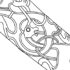
KrisWood Posted August 21, 2021 Author Share #408 Posted August 21, 2021 I found a better way to draw the frames themselves based on the measurements in the reconstruction report. The lines in the plans don't always agree with the provided measurements. Rather than trying to trace every line exactly as drawn and hoping I have pixel in the reference image at the right scale, draw circles at each point with a radius equal to the measurement, then draw more circles along the tangents of the measurement circles. The result is one beautiful and mathematically correct frame. Now is it just me or do these circles have more than a passing similarity with something carved into a different Viking ship.... GrandpaPhil, Cathead, ccoyle and 3 others 6 Quote Link to comment Share on other sites More sharing options...
KrisWood Posted August 27, 2021 Author Share #409 Posted August 27, 2021 After wrestling with the old plans trying to get them lined up with my frames from the new plans I gave up and decided to plot only the points for which the new plans give numeric values. It got me within one pixel from the reference images for the old plans, so I'm going to call it "good enough" The black line is the new intersection of the deck beams with the hull, the selected (yellow with dots) line is the mirror of the black line and represents the starboard version of the same thing. The red curves are my old lines. mtaylor and GrandpaPhil 2 Quote Link to comment Share on other sites More sharing options...
KrisWood Posted August 27, 2021 Author Share #410 Posted August 27, 2021 Quick note to anyone trying to build from the plans in Rekonstruktion af Osebergskibet Bind I & II. The drawings do not always line up with the numbers. Always err on the side of the numbers, except when the numbers disagree with each other (they conflict sometimes but it's usually pretty obvious which is the correct one). In the event that a drawing in Bind II is significantly different from the numbers and / or other drawings, Ms Bischoff has done a VERY thorough job of explaining the correct measurements and their reasons in Bind I. Quick note to self, always check the documentation!!! Now to redraw some things that I made faulty assumptions on... Louie da fly and mtaylor 2 Quote Link to comment Share on other sites More sharing options...
KrisWood Posted August 28, 2021 Author Share #411 Posted August 28, 2021 (edited) While reading the work more thoroughly, I found the reason for the few discrepancies in Bind II. In "Rekonstruktion af Osebergskibet Bind I" Chapter 6.2 page 98, Bischoff explains that some of the plans were hand drawn but processed digitally in Photoshop, and others were entirely digital and drawn in Rhinoceros. Because Photoshop uses a raster interface rather than a vector one, it cannot do exact measurements. It can only do measurements to the nearest pixel at the working scale. This thread is getting ridiculously long and I'm not even building with wood again yet, so I'll combine my next post with my last one. I don't know if any of you remember how many months I spent agonizing over the keel alone. Even after I bought the Saga Oseberg book by Thomas Finderup I couldn't figure out exactly how it was shaped. Now I've got exact numbers for every single curve of it. Here is one mathematically perfect keel. Edited August 28, 2021 by KrisWood GrandpaPhil, Siggi52, Archi and 3 others 6 Quote Link to comment Share on other sites More sharing options...
mtaylor Posted August 29, 2021 Share #412 Posted August 29, 2021 Don't worry about how long this topic is. Research is a big part of any scratch build where you have to make your own plans. AnobiumPunctatum and KrisWood 2 Quote Mark "The shipwright is slow, but the wood is patient." - me Current Build: Past Builds: La Belle Poule 1765 - French Frigate from ANCRE plans - ON HOLD Triton Cross-Section NRG Hallf Hull Planking Kit HMS Sphinx 1775 - Vanguard Models - 1:64 Non-Ship Model: On hold, maybe forever: CH-53 Sikorsky - 1:48 - Revell - Completed Licorne - 1755 from Hahn Plans (Scratch) Version 2.0 (Abandoned) Link to comment Share on other sites More sharing options...
AnobiumPunctatum Posted August 29, 2021 Share #413 Posted August 29, 2021 Quote This thread is getting ridiculously long and I'm not even building with wood again yet, Yes, and every part is really interesting. . So don't worry about this mtaylor and KrisWood 2 Quote Regards Christian Current build: HM Cutter Alert, 1777; HM Sloop Fly, 1776 - 1/36 On the drawing board: English Ship Sloops Fly, 1776, Comet, 1783 and Aetna, 1776; Naval Cutter Alert, 1777 Paused: HMS Triton, 1771 - 1/48 "Have no fear of perfection - you'll never reach it." Salvador Dali Link to comment Share on other sites More sharing options...
KrisWood Posted September 9, 2021 Author Share #414 Posted September 9, 2021 Gradually adding more and more things from the new report to the model, by number rather than by eyeball. Archi, mtaylor, bigpetr and 1 other 4 Quote Link to comment Share on other sites More sharing options...
KrisWood Posted September 9, 2021 Author Share #415 Posted September 9, 2021 (edited) I've got a problem. My hand drawn lines for the ship are out of alignment. I'm not sure when it happened or how, but for some reason the plans themselves don't seem to agree with each other even within two views of the same plan... So frustrating... In short, I successfully plotted my projection surfaces by the numbers and projected my frames onto them at the correct angles! Then I realized, the surfaces were too small. I did some troubleshooting and found that my hand drawn top view is too narrow by a few centimeters, despite the fact that all my reference image views are the same scale! I have no idea where I went wrong here. In the attached image the yellow line is plotted with math calculating the angle at which the inclined frame intersects the top inner edge of each plank of the hull. The blue line is hand drawn and represents where the front view says those points should be. Can anyone PLEASE give me some tips on correctly setting up references images in Rhino so that they're all the correct scale? These are all based on raster reference images that include multiple points with scales written. Thanks, Kris Edit: Well, I figured out my problem. I've been drawing all my curves as projections from two curves, mostly top view and side view. The ship exists in three dimensional space so Rhino projects the two views as if they were distributed evenly across the entire length of the space. In reality there is a third front/rear view which would inform where on the other two curves each point should fall, but I don't see a way to create curves from three views... Edited September 9, 2021 by KrisWood Louie da fly, bigpetr and mtaylor 2 1 Quote Link to comment Share on other sites More sharing options...
bigpetr Posted September 11, 2021 Share #416 Posted September 11, 2021 Hi Kris, great you are back to the project with full swing and with invaluable new source of info published by Vibeke. KrisWood and mtaylor 2 Quote Link to comment Share on other sites More sharing options...
KrisWood Posted September 11, 2021 Author Share #417 Posted September 11, 2021 I hate to say it, but I think I must admit defeat on the Rhino front. I simply cannot get all three views to align with each other no matter what I do. If I draw a line in one view, it doesn't match the others. To test this out I went back and re-drew just the garboard strake by extending the contact surface of the keel / rabbets. to the first line in each view. No two views lined up with each other. Furthermore, after reading more of Ms Bischoff's report, I realize that there are only three dimensions that matter in the entire ship now that I have scaled plans for the planks. Those dimensions are the width of the keel, the width of the contact surface with the garboard strake, and the thickness of the planks. All other dimensions can be derived from these because the hull is built keel, then strakes, then frames. Unfortunately I lack the woodworking skills to fashion the keel, so even through I have drawn it accurately in Rhino, I cannot make it in wood until I can save up for a CNC mill. One day... mtaylor 1 Quote Link to comment Share on other sites More sharing options...
AnobiumPunctatum Posted September 12, 2021 Share #418 Posted September 12, 2021 I've done the step in the other direction. I own since a fey days a cnc-mill and now I am saving my money for Rhino. Is it possible that the three views are not really perpendicular to each other? I know the same form my 2D works. The point on the drawings are the same but not the 2D representation of the lines. There are always small differences. It's a problem with using splines. KrisWood 1 Quote Regards Christian Current build: HM Cutter Alert, 1777; HM Sloop Fly, 1776 - 1/36 On the drawing board: English Ship Sloops Fly, 1776, Comet, 1783 and Aetna, 1776; Naval Cutter Alert, 1777 Paused: HMS Triton, 1771 - 1/48 "Have no fear of perfection - you'll never reach it." Salvador Dali Link to comment Share on other sites More sharing options...
KrisWood Posted September 12, 2021 Author Share #419 Posted September 12, 2021 32 minutes ago, AnobiumPunctatum said: I've done the step in the other direction. I own since a fey days a cnc-mill and now I am saving my money for Rhino. Is it possible that the three views are not really perpendicular to each other? I know the same form my 2D works. The point on the drawings are the same but not the 2D representation of the lines. There are always small differences. It's a problem with using splines. Hi Christian, This is very possible. I think it's more that the original drawing was done in Rhino, then rendered to PDF as a raster image, then the pixels have been brought back into Rhino. Thus it's very difficult to tell exactly which pixel goes at exactly which point. You can get a 90 day trial of Rhino for free from their website. mtaylor and AnobiumPunctatum 2 Quote Link to comment Share on other sites More sharing options...
AnobiumPunctatum Posted September 12, 2021 Share #420 Posted September 12, 2021 34 minutes ago, KrisWood said: You can get a 90 day trial of Rhino for free from their website. I know, but one step after the other. Before I start with Rhino, I will prcatice with my new toy. For the first steps I use my old 2D CAD. mtaylor 1 Quote Regards Christian Current build: HM Cutter Alert, 1777; HM Sloop Fly, 1776 - 1/36 On the drawing board: English Ship Sloops Fly, 1776, Comet, 1783 and Aetna, 1776; Naval Cutter Alert, 1777 Paused: HMS Triton, 1771 - 1/48 "Have no fear of perfection - you'll never reach it." Salvador Dali Link to comment Share on other sites More sharing options...

Recommended Posts
Join the conversation
You can post now and register later. If you have an account, sign in now to post with your account.