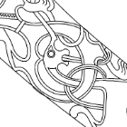
KrisWood Posted June 28, 2020 Author Share #211 Posted June 28, 2020 Finished drawing the new keel and stem dimensions. Now to figure out how to get cross sections for the layers of wood to cut out. Does anyone here use Rhino, and if so can you give some advice? The red lines are the rabbet lines in the stems and the T of the keel in the middle. GrandpaPhil, bigpetr, Larry Cowden and 1 other 4 Quote Link to comment Share on other sites More sharing options...
bigpetr Posted June 29, 2020 Share #212 Posted June 29, 2020 You can use Contour function in Rhino to make cross sections. http://docs.mcneel.com/rhino/5/help/en-us/commands/contour.htm KrisWood and Larry Cowden 2 Quote Link to comment Share on other sites More sharing options...
KrisWood Posted June 29, 2020 Author Share #213 Posted June 29, 2020 Hi @bigpetr, Thanks! I tried following your suggestion and all it gave me was cylindrical rope-like surfaces following the length of each curve, as if someone had built my wireframe floating in space made out of yarn. How do I get it to treat my curves as a single object instead of just a collection of curves / how do I get it to correctly understand the shapes described by those curves? Thanks! Kris Quote Link to comment Share on other sites More sharing options...
KrisWood Posted June 29, 2020 Author Share #214 Posted June 29, 2020 I think I figured it out. What I'd interpreted as ropes or yarn are actually strings of points along my curves. In order to get cross section curves I need to do the contour function on a surface. I've started making the surfaces but the learning curve is pretty steep. >.< Larry Cowden and mtaylor 2 Quote Link to comment Share on other sites More sharing options...
KrisWood Posted July 1, 2020 Author Share #215 Posted July 1, 2020 I've completed redrawing my keel, with contour profiles and scarfs. I doing so I figured out one of the reasons my scarfs joining the stems to the keel keep failing. At first I sliced a plane through my lines at the angle shown in the plans. No matter how I sliced it I kept getting terrible results and I was unable to get a plane to go through all the lines in the right spot. Then I remembered what the scarfs looked like on the original. They're not planar, they're curved. In seconds I had scarfs drawn that looked identical to those in the reconstruction. Now, how would you cut these out of wood? 🤪 mtaylor, Larry Cowden and GrandpaPhil 3 Quote Link to comment Share on other sites More sharing options...
KrisWood Posted July 1, 2020 Author Share #216 Posted July 1, 2020 The best I can think to do is slice my profiles using these scarfs, then as I build it up in layers either scarf each layer together as I glue it on... ...OR... leave each layer squared and end to end at the point where the curve intersects the layer.... Larry Cowden and mtaylor 2 Quote Link to comment Share on other sites More sharing options...
Schrader Posted July 1, 2020 Share #217 Posted July 1, 2020 On 12/1/2019 at 1:28 AM, KrisWood said: Hi everyone! It's been a while since I posted in these forums, but I'm starting my first wooden ship model so I figured it was time to start a build log thread. For this first project, I decided to build the Oseberg Viking longship. So far the best plans I've found are here: http://oseberg.narod.ru/pages/Oseberg_Schiff_Spiegazioni_Pag_01.htm If anyone knows of any other publicly accessible plans that are better, I'd love to hear about them. This appears to be from a kit model but I think that might make it easier for a first build. I'll post pics as I make progress. Edit: I've updated the title to reflect the plans I've settled on, which have changed multiple times since I started this thread. I'm now working from the plans by Vibeke Bischoff that were used to build the Saga Oseberg 1:1 replica, from the book, "Saga Oseberg: rekonstruktion af et vikingeskib" by Thomas Søes Finderup, master boat builder of the Saga Oseberg replica. I have the Viking as my next project......... I’ll be here learning from you KrisWood and mtaylor 2 Quote Link to comment Share on other sites More sharing options...
KrisWood Posted July 2, 2020 Author Share #218 Posted July 2, 2020 I sliced all my lines today into 1/16" layers, did away with the scarf in the keel (it serves no purpose that I can see) and into groups of layers based on what part it goes with. Here are the new keel layers. The middle is two layers thick at the moment which would make it 1/8" but I think I'll combine the two on either side into it to make it a 1/4" keel, about the width of the vertical portion of the T of the keel at 1:25 and then add the outer layers one at a time to build up the horizontal portion of the T. Color coding: Brown: inner contour edge of a layer Purple: outer contour edge or scarf of a layer which connect to another layer Green: outer sides of the keel lines Black: Top of the keel lines Blue: Rabbets and underside of the T shape of the keel Larry Cowden 1 Quote Link to comment Share on other sites More sharing options...
KrisWood Posted July 4, 2020 Author Share #219 Posted July 4, 2020 Finished applying the same treatment to the stems, and made the purple lines dashed, then separated the layers in Photoshop for printing. I misspoke before, the slices are 1/32" not 1/16". The bottom of my keel will be 3/16" or about 0.5cm. These lines are my own, based on math rather than on the lines from any particular drawing. Edit: Hmmm I looked through my supply of wood and I don't actually have any 1/32" basswood to work with. Now that I think of it I don't think I've seen any in the hobby shop either. Judging by how thin 1/16" is, the 1/32" would be like paper anyway. I think I'll rearrange my layers to use 1/16" instead. BRB! GrandpaPhil, mtaylor and Larry Cowden 3 Quote Link to comment Share on other sites More sharing options...
KrisWood Posted July 4, 2020 Author Share #220 Posted July 4, 2020 Ok, what would be easier to build, the one above at 1/32" except for the middle layer which is 1/16", or the below four layers at 1/16" each? I'll have to redraw the scarfs to accommodate the 1/16" version but that's not terribly difficult. Cathead, mtaylor, Larry Cowden and 1 other 4 Quote Link to comment Share on other sites More sharing options...
Cathead Posted July 4, 2020 Share #221 Posted July 4, 2020 No idea, never tried to do what you're trying. mtaylor 1 Quote Eric Current builds: scratchbuilt Missouri River steamboat Peerless (1893); 1:1 scale timber-framed outdoor kitchen Nautical builds (kits): USS Cairo; NRG capstan project; NRG half-hull; Viking longship; US revenue cutter; 18th century longboat; Bounty launch Missouri River craft (scratchbuilt): 1853 Missouri River steamboat Arabia; 1865 steamboat Bertrand; Lewis & Clark barge; keelboat; 1876 steamboat Far West Link to comment Share on other sites More sharing options...
KrisWood Posted July 6, 2020 Author Share #222 Posted July 6, 2020 Ok, let's try a different way of asking the same question: If you were building up a keel out of layers instead of as a single piece, do you think it would be easier to cut more thinner layers, or less thicker layers? Thinner layers means smaller steps between layers and less shaping work in the filing and sanding department. Thicker layers means less cutting out of pieces and less chance that they'll get glued on at the wrong angle, but more shaping work and a higher likelihood of sanding too much or too little. Also related, would you shape your layers (the sanding and filing to the right thickness) before or after gluing them all together? This feels like I'm starting all over again. I'm back to the very first problem I had, of not knowing how to work the wood in the first place. 😣 GrandpaPhil, mtaylor and Larry Cowden 3 Quote Link to comment Share on other sites More sharing options...
mtaylor Posted July 7, 2020 Share #223 Posted July 7, 2020 I"m unable to answer your question as I make my keels out of one piece and "fake" scarf joints where needed. Cathead 1 Quote Mark "The shipwright is slow, but the wood is patient." - me Current Build: Past Builds: La Belle Poule 1765 - French Frigate from ANCRE plans - ON HOLD Triton Cross-Section NRG Hallf Hull Planking Kit HMS Sphinx 1775 - Vanguard Models - 1:64 Non-Ship Model: On hold, maybe forever: CH-53 Sikorsky - 1:48 - Revell - Completed Licorne - 1755 from Hahn Plans (Scratch) Version 2.0 (Abandoned) Link to comment Share on other sites More sharing options...
Cathead Posted July 7, 2020 Share #224 Posted July 7, 2020 I have never done what you're trying but my personal instinct would be to use more layers initially to minimize the amount of shaping later. This lowers the risk of difficult-to-repair mistakes in shaping, whereas you can always recreate an initial cut if you don't like how it came out. But again, this is not based on actual experience. I supposed you could try shaping the layers before gluing by clamping everything together really well, but it could be difficult to recreate the exact configuration when gluing. You're on your own here, I think. Louie da fly, KrisWood and mtaylor 3 Quote Eric Current builds: scratchbuilt Missouri River steamboat Peerless (1893); 1:1 scale timber-framed outdoor kitchen Nautical builds (kits): USS Cairo; NRG capstan project; NRG half-hull; Viking longship; US revenue cutter; 18th century longboat; Bounty launch Missouri River craft (scratchbuilt): 1853 Missouri River steamboat Arabia; 1865 steamboat Bertrand; Lewis & Clark barge; keelboat; 1876 steamboat Far West Link to comment Share on other sites More sharing options...
KrisWood Posted July 7, 2020 Author Share #225 Posted July 7, 2020 Thanks @Cathead, your ideas make a lot of sense! I guess I'll just wing it and see how it comes out. Worst case scenario I can always cut it out again the other way if one doesn't work out. Louie da fly and mtaylor 2 Quote Link to comment Share on other sites More sharing options...
KrisWood Posted July 15, 2020 Author Share #226 Posted July 15, 2020 Minor update: I'm still in the process of redrawing my plans now that @bigpetr taught me some tips for using Rhino more effectively. There are still some issues to figure out before printing my next parts to cut out but I'm making progress every day. bigpetr, Cathead, Ekis and 4 others 7 Quote Link to comment Share on other sites More sharing options...
Louie da fly Posted July 16, 2020 Share #227 Posted July 16, 2020 The CAD work is fascinating, Kris. But I'm really looking forward to seeing it all"in the flesh" when you start building. I will be very interested in seeing how well the drawing transfers over to the real world. Naturally hoping it all goes off without a hitch, but even if it doesn't to start off with, a very well worthwhile exercise. KrisWood 1 Quote It's not really a ship model unless you've bled on it. CURRENT BUILDS Venetian merchant Ship from Basilica of San Marco Golden City - Ballarat paddlewheeler FINISHED Australian couta boat RMS Titanic HMVS Cerberus 11th century Byzantine dromon Winchelsea Nef - Late 13th century Mediaeval ship Henry Grace a Dieu - Rebuild of 1:200 model I started in 1967 https://modelshipworld.com/topic/36379-mistydeefer-by-louie-da-fly-finished-restoration-decor-yacht/#comment-1040663 Mistydeefer - restoration of decor model yacht Link to comment Share on other sites More sharing options...
KrisWood Posted July 16, 2020 Author Share #228 Posted July 16, 2020 @Louie da fly, I'm eager to get back into the wood myself, but in cutting out my last few pieces (and in ruining my fourth keel) I've learned that what seems like it should work in the plans doesn't necessarily work in wood. I'm learning the tired axiom "measure twice, cut once" the hard way. In the process of re-drawing my plans I've found several places where I'd misinterpreted lines in the original Oseberg reconstruction plans in my previous attempts. That means my previous keel and frame templates would never have lined up. I would have done a LOT of filing and sanding and forcing things into place, all to end up with a rather lumpy and inaccurate model. This time around I'm making sure every measurement of every component in the CAD drawing lines up exactly before printing a single template. Louie da fly, mtaylor and Larry Cowden 3 Quote Link to comment Share on other sites More sharing options...
KrisWood Posted July 22, 2020 Author Share #229 Posted July 22, 2020 I've got the inside of each strake mapped out! Next up will come fitting the curves into the rabbets and then I can start working on mapping out the internal structures. Cathead, Binho, Larry Cowden and 6 others 9 Quote Link to comment Share on other sites More sharing options...
liteflight Posted August 5, 2020 Share #230 Posted August 5, 2020 I love both your CAD work (well beyond me) and your voyage of discovery about the plans and methods of turning them into a valid Oseberg ship. A couple of points you raised earlier: 1)how to produce the keel shape with the limited tools at your disposal I believe you have a power tool of some sort. I would manufacture a holder for it so that you can fix it to the bench (or an angle plate) This only needs to be wood with holes cut and split to clamp the tool. OR Mould a holder using silicone moulding goop (knead corn flour (cornstarch) into any RTV silicone till it is stiff enough, put tool in plastic bag (or wrap in kitchen film) and mould a holder from the silicone goop - leave to harden Then you could mill, sand or gouge the basic shape of the keel carefully to rough dimensions and 2) how to make treenails its not Nordic Drakkar building, but treenails in all sizes are easy to make from bamboo** split skewer roughly using a blunt knife make a draw plate* with lots of hole size options point one end of a bit of bamboo - push through a hole from the burred side, grab with pliers and pull through repeat till you have the size you need This is what Harold Underwood does with EVERY joint on his POF ship models *to make a draw plate (quick, nasty and effective) Find a bit of metal about 1/16th (1.5mm thick) mine is a disused brass dial disc using a masonry (hardened) nail - punch lots of holes in the plate using different force so as to produce different hole sizes there will be a pronounced burr on the back - good, it does no harm- but it could be partly stoned off to provide a sharp edge **Viking treenails would have been oak, and this might just work with White oak? other candidate woods might be ash or poplar. If you let us know where you are in the world, we could probably make more specific suggestions to help. A window photo you posted showed wooden tiles/shingles, which suggested to me Scandanavia or North America keep up the good work andrew Larry Cowden, KrisWood, Louie da fly and 1 other 4 Quote Andrew "Pas d’elle yeux Rhone que nous” Kits under the bench: Le Hussard (Started in the 1980s) Scratch builds: Volante, Brig (R/C): Footy Drakkar "Rodolm" (R/C). Longship Osberg (R/C) Link to comment Share on other sites More sharing options...
KrisWood Posted August 6, 2020 Author Share #231 Posted August 6, 2020 Hi @liteflight, Thanks for the tips! I've been thinking about trying toothpicks through a drawplate for the treenails, but if they don't actually add any structural integrity I might skip them entirely. If I do I'll probably leave the ends sticking out and paint them black to make them look more like iron rivets. I don't see myself messing with moulding goop but I have been considering making a miniature mill stand out of wood / metal for my Dremel. Unfortunately I get very little time as it is for my project, so I'd rather spend that time working on my ship the old fashioned way instead of making a whole new project of building tools. I see you have an Oseberg build listed in your signature. Do you have any photos of your model and/or your build when it was in progress? (Edit: I found your build log and will be following! I've been thinking about building an RC version of the Oseberg ship after this first one, since this first one is destined for the sea.) I live in Oregon in the USA. My house has split cedar shingles because it was built in 1900 by one of the original pioneer families in my area. mtaylor and Larry Cowden 2 Quote Link to comment Share on other sites More sharing options...
liteflight Posted August 8, 2020 Share #232 Posted August 8, 2020 Not sure that toothpicks would work in a draw plate, but it would be easier to try that opine. Whet I locate my draw plate I will try some different woods treenails will always strengthen a joint - Harold Underwood made his of split bamboo as I described, and dipped tham in “knotting” as a glue before tapping them into pre-drilled holed. I have not seen or heard of knotting for sale for the past 50 years. I would use white glue! On 8/7/2020 at 6:12 AM, KrisWood said: I live in Oregon in the USA. My house has split cedar shingles because it was built in 1900 by one of the original pioneer families in my area. Ok, got you. Now cedar is a stringy, fibrous wood. Split a shingle and that would work in a draw plate 😀 A stand of any sort for your Drexel is like having another hand! And if it held it vertical you would have either a drill/mill or a spindle Moulder (molder) I stand In awe of your computer model. I can see it snaking over the rollers with huge bone in its teeth. mtaylor and KrisWood 2 Quote Andrew "Pas d’elle yeux Rhone que nous” Kits under the bench: Le Hussard (Started in the 1980s) Scratch builds: Volante, Brig (R/C): Footy Drakkar "Rodolm" (R/C). Longship Osberg (R/C) Link to comment Share on other sites More sharing options...
KrisWood Posted August 12, 2020 Author Share #233 Posted August 12, 2020 Personal preference question for you all... Regularly spaced frames perpendicular to the center line, or irregularly spaced diagonal frames placed as they were in the original ship? Glende's in-situ drawing from the excavation: http://www.unimus.no/felles/bilder/web_hent_bilde.php?id=12417098&type=jpeg Johannesen's reconstruction drawing as the ship was assembled in the museum: http://www.unimus.no/felles/bilder/web_hent_bilde.php?id=12384240&type=jpeg Glende's drawing is closer to how it would have been originally, but is missing parts that were already destroyed when the ship was excavated. I suspect doing straight, frames at each station (except of course the small diagonal frames at the bow and stern) will be easier to build, though of course not as true to the original. What I don't know is whether the diagonal frames had anything to do with the structural integrity of the hull. For this project I think I want whichever is stronger and easier to build, but would rather have stronger if easier means a less sturdy final result. I'm finishing up redrawing my planks now and will need to decide this before redrawing the frames to work with the new keel. What are your thoughts on this? mtaylor and Larry Cowden 2 Quote Link to comment Share on other sites More sharing options...
Louie da fly Posted August 12, 2020 Share #234 Posted August 12, 2020 That's very interesting, Kris. I hadn't known about it before. Also the frames all lean over slightly in the vertical plane, towards the ends. It certainly looks as if they did that on purpose, and they must have had their reasons, perhaps to oppose the forces of waves crashing against the hull from bow and stern. I can't really see that the diagonals you mention would have affected the structural strength particularly, but the vertical lean might have. Keep in mind that these ships were built "shell-first" with the shape of the hull determined by the planks and the frames added afterwards, so they might not have worried all that much that the frames weren't quite evenly spaced, or exactly square. But in building the model I really can't see that any slight structural advantage that might be conveyed by the diagonal and leaning frames would make any perceptible difference to the strength of the model - your clinker built vessel will be more than strong enough, if my own dromon (even more delicately built - and of carvel construction) is anything to go by. So, it then comes down to whether you want to copy the frames exactly for historical accuracy's sake, or just build it in a way that will be easier on you. I doubt very much that the strength will be affected at all. And I doubt that anybody but you will ever notice the difference. KrisWood, Cathead, Larry Cowden and 1 other 4 Quote It's not really a ship model unless you've bled on it. CURRENT BUILDS Venetian merchant Ship from Basilica of San Marco Golden City - Ballarat paddlewheeler FINISHED Australian couta boat RMS Titanic HMVS Cerberus 11th century Byzantine dromon Winchelsea Nef - Late 13th century Mediaeval ship Henry Grace a Dieu - Rebuild of 1:200 model I started in 1967 https://modelshipworld.com/topic/36379-mistydeefer-by-louie-da-fly-finished-restoration-decor-yacht/#comment-1040663 Mistydeefer - restoration of decor model yacht Link to comment Share on other sites More sharing options...
bigpetr Posted August 12, 2020 Share #235 Posted August 12, 2020 I am with Louie. I think vertical lean will affect structural strength, diagonals not so much on fullscale ship. I think diagonal lean was affected by shape of grown timber they ware able to get for the ribs. When they found something close, they just place it little diagonaly to fit to the shape of the hull. But this is just my theory. I think none of the lean (vertical or diagonal) will make difference in sailing behaviour of scale model where forces are different. So (assuming all deck planks will be instaled on your model = inside of the ship not visible ) I would make ribs under floor level paralel in all axis and visible parts of beams and knees at angles as original have (or at least the vertical lean, because it will have more prominent visual impact then diagonals). I am solving similar dilema with my Gokstad build, because all plans shows paralel ribs, but reconstructed original has some of them at angles. mtaylor, Larry Cowden, KrisWood and 1 other 4 Quote Link to comment Share on other sites More sharing options...
KrisWood Posted August 12, 2020 Author Share #236 Posted August 12, 2020 Thank you @Louie da fly and @bigpetr! I think I'll go with perpendicular to the center line and either straight vertical or vertical lean for my frames. Larry Cowden, mtaylor, Cathead and 1 other 4 Quote Link to comment Share on other sites More sharing options...
Binho Posted August 15, 2020 Share #237 Posted August 15, 2020 Hey Kris, those highly detailed drawings are not actually 'in situ' archaeological drawings, they are reconstructions themselves. Don't rely on them too heavily. The actual ship was severely distorted and fragmentary when found, having been compressed under multiple tons of dirt for some 1200 years. The floor timbers in some places were actually sticking up above the sheerstrake: More of the actual excavation photos are here: http://viking.archeurope.info/index.php?page=oseberg-ship-the-excavation In 1904 archaeology was still pretty dodgy in a lot of places. Idealized reconstructions like that were pretty common. It was only really in the 1920's and 30's that archaeology became more systematic. I don't think we have actual drawings of what either the Oseberg or the Gokstad looked like when actually found. To me it's seems unlikely that the frames were actually leaning like that. It looks like they reconstructed the ship without enough rocker, having straightened out the keel so it looked "better", and then tried to make the warped frames fit the reconstructed hull line. In the Skuldelev ships the floors/frames appear to have been roughly perpendicular to the keel. I'd rely more on the recently published reconstruction and the Saga Oseberg, and go with frame angles that work for you. Use the original drawings more for reference of construction details than actual plans. mtaylor, Larry Cowden, aaronc and 1 other 4 Quote Alberto - "Binho" Current Build: Dusek 1:72 Scale Longship Digital Shipyard: Viking-era ships and boats 3D Art: Artstation, Sketchfab Link to comment Share on other sites More sharing options...
KrisWood Posted August 15, 2020 Author Share #238 Posted August 15, 2020 Hi @Binho, Thank you for your detailed reply and the photos! Yes, I realize that Glende's drawing of the full ship is a reconstruction, but it is different in a few aspects from the other reconstructions. Glende was an engineer present at the dig. He took detailed measurements of each part in situ as it came out of the ground, see attached image of the crushed hull measured as it was uncovered. He then used these measurements to realign all parts as he imagined they would have fit together, mathematically. Most other drawings of the ship are based off Johannessen's reconstruction which is how he rebuilt the ship as it looks in the museum today. Johsannessen (the museum conservator who built the display) worked from the parts as they looked after being disassembled in an uncontrolled environment for two years. Many of the parts had shrunk and warped in that time, and needed be repeatedly steamed and chemically treated in order to get into a shape (and to stay in a shape) that he found appealing. Both Glende and Johannessen show a straight keel, but the keel was broken in several places and squished flat by the burial mound collapsing on top of it. Johannessen also intentionally broke several of the frames to make the ship narrower as a whole. To create Saga Oseberg's lines, Vibeke Bischoff used computer aided design techniques combined with detailed observations of flow of the wood grain in each broken segment of the keel to mathematically reconstruct what the keel would have originally looked like. She also compared Glende's in situ drawings of the frames with the museum display to extrapolate the original breadth of the ship at each cross section, resulting in a broader, rounder hull toward the bow. Anyway, TL:DR, Glende's drawing is more accurate than Johannessen's because it's based on math and in-situ observation, even if the ship wasn't in the shape he drew in his final reconstruction when they excavated it. Ms Bischoff's plans are superb, but do not show every detail. For those I mostly go to Glende because he actually did the numbers, where Johannessen worked from his imagination. Binho, mtaylor, GrandpaPhil and 1 other 4 Quote Link to comment Share on other sites More sharing options...
KrisWood Posted August 15, 2020 Author Share #239 Posted August 15, 2020 In this cross section of the dig site from the 1904 excavation you can see how the longhouse built over the ship, and then the mound built over the longhouse, together collapsed on top of the ship, pushing the sides down below the keel: GrandpaPhil, Larry Cowden and Binho 3 Quote Link to comment Share on other sites More sharing options...
Binho Posted August 16, 2020 Share #240 Posted August 16, 2020 Ah, so there actually are stratigraphic drawings and the like! Cool! How have you been finding them? I’d be really interested to see them all. Do they have Glende’s original excavation drawings too? There is so much info online, but it can be hard to find sometimes. I was also hoping the full 1917 excavation report would be online, but haven’t been able to find it. I guess my main point of contention is that the off-axis frames are being interpreted as an intentional design feature, when to me they look to be an artifact of Gelde’s preferred reconstruction. According to a google translate of the part of Bischoff’s paper that deals with the background of Gelde’s drawings (pg. 18 of the PDF you linked earlier in the thread), while generally very accurate, some of Gelde’s excavation drawings were nevertheless incomplete or had incorrect measurements, in part because some sections of the ship were so fragmentary. His 1909 reconstruction you linked was drawn after the ship had been re-erected, with extra measurements taken during the process. It was also based on the going theory at the time that the oarports had to be as level as possible, which is what ultimately produced the squished shape in Gelde’s reconstruction and the following ones. Even with accurate measurements, it’s easy to contort things if you have a specific theory in mind. Cathead and Larry Cowden 2 Quote Alberto - "Binho" Current Build: Dusek 1:72 Scale Longship Digital Shipyard: Viking-era ships and boats 3D Art: Artstation, Sketchfab Link to comment Share on other sites More sharing options...

Recommended Posts
Join the conversation
You can post now and register later. If you have an account, sign in now to post with your account.