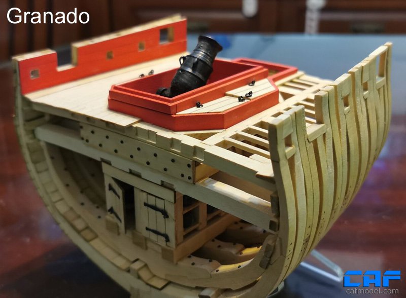
James H Posted February 10, 2021 Share #1 Posted February 10, 2021 Hi all, I'm actually waiting on a couple of small sheets of parts from CAF, and those should be here pretty soon, courier dependent. The kit itself landed last week in under 7 days from China, via TNT/FedEx. Pretty quick for these times we currently live in. If you haven't already checked out my review for this kit, please do so here: I still need to dump my photos from camera yet, and I'll wait until I have the first double frame complete. Give me a couple of days or so Jim Rustyj, mtaylor, GuntherMT and 5 others 8 SAY NO TO PIRACY. SUPPORT ORIGINAL IDEAS AND MANUFACTURERS. KEEP IT REAL! On the bench: HMS Indefatigable - 1794 (production prototype), Vanguard Models - 1:64. On Hold: HMS Winchelsea Double Capstan - Syren Ship Models - 1:48 Finished US Baltimore Armed Privateer Schooner Grecian 1812 (prototype) - Vanguard Models - 1:64 'Zulu' fishing boat, Vanguard Models - 1:64 Fifie' fishing boat, Vanguard Models - 1:64 HMS Flirt 1782, Vanguard Models - 1:64. Duchess of Kingston c.1780 - Vanguard Models - 1:64 HMS Sphinx 1775, Vanguard Models - 1:64 ERYCINA - Plymouth Ketch-Rigged Trawler 1882, Vanguard Models - 1:64. 'Nisha' - The Brixham 'Mumble-Bee' - Vanguard Models 1:64 'Saucy Jack' fishing boat - Vanguard Models - 1:64 Ranger 'Barking Fish Carrier' - 1864 - Vanguard Models - 1:64 Indeterminate: Tender Avos - Master Korabel - 1:72. H.M.S. Victory (production prototype) - Amati - 1:64. HMS Granado 1742 (cross section) - CAFModel - 1:48 Link to comment Share on other sites More sharing options...
James H Posted February 11, 2021 Author Share #2 Posted February 11, 2021 Ok, I've decided to dump down the photos I've currently got on this one as FedEx has twice delayed my missing parts sheets. Please remember, I've never done a POF before, so this is definitely out of my comfort zone. If you see anything untoward, feel free to make suggestions. 😊 Not sure what timber is used in this kit, but it's very similar to boxwood that I've used in models many years ago, and also at school. It's reasonably yellow, quite hard and with a fine grain. All sheets in the kit really need to be numbered as per the parts plan in the rear of the manual. You definitely don't want to mix any of these parts up. Parts removal is also very easy, with some cleanup required on tabs. A small number of the machined surfaces also look a little 'fluffy'. Until everything is sanded, I found that a simple shave/scrape with a blade was sufficient enough to sort it. whoops! upside down numbers! I've started by building frames #6, 7 and 8, and for the moment, also the 'B' part of each of those frames, which is the rear of each double frame (towards the stern, of course). Before any building, there are some filler parts which need to be glued to the plans (all frames except #14), so this was done from the outset. A hatched area on each frame drawing indicates where these fit. Also refer to my post about corrections to plans for fillers on #7 and #8 frames. A number of the top timbers are CNC-machined to shape, on both parts A & B of some frames. These just need to be snipped out from the sheet 9A and then cleaned up. Temporary resin inserts are provided to add some gaps/spaces between some frame A & B sided, and the CNC parts need to have their 'V' notches properly cut into place so accommodate the resin spacers. Each set of spacers is also numbered specific to the frame you are working on. All parts of each frame B (in turn) are removed from the various sheets and cleaned up. As this stuff is CNC routed, all internal corners are rounded and will need to be squared off. I used a scalpel for this and it only takes a minute or so per joint. For gluing, I use Evo-Stick formula wood glue, and I also bevelled the timber joint as per plan (and the chocks).....BUT, it took me ages to make a single joint and to get it to fit more or less gap free. I've since found these joints are NOT angled/bevelled and should be perpendicular to the frame....no angled chocks either! I can't tell you how pleased that made me. There are a few laser engraved marks to show bevelling of these, so I'm just ignoring them. Only Frame 6B has them on mine, and the others won't. NOTE: When assembling, note the bevelling lines on the timbers, and that the red lines on the plan are for the REARMOST extremity of each frame 'B'. Frame work so far: Whilst waiting for my parts to arrive vis FedEx, I assembled the two keel parts. Again, there is a certain amount of cleaning up to do, but I think the results look quite neat. Back to the cave... thibaultron, JpR62, JeffT and 20 others 23 SAY NO TO PIRACY. SUPPORT ORIGINAL IDEAS AND MANUFACTURERS. KEEP IT REAL! On the bench: HMS Indefatigable - 1794 (production prototype), Vanguard Models - 1:64. On Hold: HMS Winchelsea Double Capstan - Syren Ship Models - 1:48 Finished US Baltimore Armed Privateer Schooner Grecian 1812 (prototype) - Vanguard Models - 1:64 'Zulu' fishing boat, Vanguard Models - 1:64 Fifie' fishing boat, Vanguard Models - 1:64 HMS Flirt 1782, Vanguard Models - 1:64. Duchess of Kingston c.1780 - Vanguard Models - 1:64 HMS Sphinx 1775, Vanguard Models - 1:64 ERYCINA - Plymouth Ketch-Rigged Trawler 1882, Vanguard Models - 1:64. 'Nisha' - The Brixham 'Mumble-Bee' - Vanguard Models 1:64 'Saucy Jack' fishing boat - Vanguard Models - 1:64 Ranger 'Barking Fish Carrier' - 1864 - Vanguard Models - 1:64 Indeterminate: Tender Avos - Master Korabel - 1:72. H.M.S. Victory (production prototype) - Amati - 1:64. HMS Granado 1742 (cross section) - CAFModel - 1:48 Link to comment Share on other sites More sharing options...
JeffT Posted February 11, 2021 Share #3 Posted February 11, 2021 The resin inserts are a pretty neat feature. Edwardkenway, Canute, thibaultron and 2 others 5 Jeff In progress: Medway Longboat 1742 - Syren Ship Model Company -1/2" scale USS Constitution - Model Shipways - Scale 1:76 HMS Granado - CAF Model - 1:48 HMS Sphinx - Vanguard Link to comment Share on other sites More sharing options...
James H Posted February 12, 2021 Author Share #4 Posted February 12, 2021 On 2/11/2021 at 4:43 PM, JJT said: The resin inserts are a pretty neat feature. I just fitted those to the timbers using some rubber cement used for photo-mounting, so I hope that plan works 🤣 Also been rooting around in my attic and I think I found some suitable Madagascan ebony I can use for the wales and gunwales. If I can, that will be very neat against the boxwood-style timber. KentM, BobG, Edwardkenway and 5 others 8 SAY NO TO PIRACY. SUPPORT ORIGINAL IDEAS AND MANUFACTURERS. KEEP IT REAL! On the bench: HMS Indefatigable - 1794 (production prototype), Vanguard Models - 1:64. On Hold: HMS Winchelsea Double Capstan - Syren Ship Models - 1:48 Finished US Baltimore Armed Privateer Schooner Grecian 1812 (prototype) - Vanguard Models - 1:64 'Zulu' fishing boat, Vanguard Models - 1:64 Fifie' fishing boat, Vanguard Models - 1:64 HMS Flirt 1782, Vanguard Models - 1:64. Duchess of Kingston c.1780 - Vanguard Models - 1:64 HMS Sphinx 1775, Vanguard Models - 1:64 ERYCINA - Plymouth Ketch-Rigged Trawler 1882, Vanguard Models - 1:64. 'Nisha' - The Brixham 'Mumble-Bee' - Vanguard Models 1:64 'Saucy Jack' fishing boat - Vanguard Models - 1:64 Ranger 'Barking Fish Carrier' - 1864 - Vanguard Models - 1:64 Indeterminate: Tender Avos - Master Korabel - 1:72. H.M.S. Victory (production prototype) - Amati - 1:64. HMS Granado 1742 (cross section) - CAFModel - 1:48 Link to comment Share on other sites More sharing options...
Rustyj Posted February 13, 2021 Share #5 Posted February 13, 2021 On 2/11/2021 at 9:45 AM, James H said: Please remember, I've never done a POF before, so this is definitely out of my comfort zone. You're off to a great start! I think you will be just fine and should be real comfortable. James H, Canute and thibaultron 3 Rusty "So Long For Now" Current Builds: Speedwell Completed Build Logs: HMS Winchelsea 1/48 Duchess of Kingston USF Confederacy , US Brig Syren , Triton Cross Section , Bomb Vessel Cross Section, Cutter Cheerful, Queen Anne Barge, Medway Longboat Completed Build Gallery: Brig Syren , 1870 Mississippi Riverboat , 1949 Chris-Craft 19' Runabout Link to comment Share on other sites More sharing options...
James H Posted February 13, 2021 Author Share #6 Posted February 13, 2021 Got a little more done over the last 24hrs. Frames 7A/B, 8A/B and 9A/B are now almost built, minus bevelling. I need to fit chocks to 8A at the moment and do some refinement on all frames. Seems like a silly question, but would I actually glue the A/B frames together? It wouldn't make much sense (to me) to add another layer of potential screw-up when all frames are going to be fastened side by side in the keel....or should I glue? Maybe gluing will just create a stronger overall assembly. I'm aware that potential timber thickness tolerances could possibly cause issues if I do glue them together before fitting to keel. Whilst waiting for glue to dry under clamps etc, I took the opportunity to remove and clean up the parts for the next three double frames 9A/B, 10A/B, and 11A/B. I also removed the parts for the last three double frames 12A/B, 13A/B, and 14A/B, but these aren't yet cleaned up and the joints prepped for assembly (squaring up internal CNC curves). Gus M, Matt D, BLACK VIKING and 14 others 17 SAY NO TO PIRACY. SUPPORT ORIGINAL IDEAS AND MANUFACTURERS. KEEP IT REAL! On the bench: HMS Indefatigable - 1794 (production prototype), Vanguard Models - 1:64. On Hold: HMS Winchelsea Double Capstan - Syren Ship Models - 1:48 Finished US Baltimore Armed Privateer Schooner Grecian 1812 (prototype) - Vanguard Models - 1:64 'Zulu' fishing boat, Vanguard Models - 1:64 Fifie' fishing boat, Vanguard Models - 1:64 HMS Flirt 1782, Vanguard Models - 1:64. Duchess of Kingston c.1780 - Vanguard Models - 1:64 HMS Sphinx 1775, Vanguard Models - 1:64 ERYCINA - Plymouth Ketch-Rigged Trawler 1882, Vanguard Models - 1:64. 'Nisha' - The Brixham 'Mumble-Bee' - Vanguard Models 1:64 'Saucy Jack' fishing boat - Vanguard Models - 1:64 Ranger 'Barking Fish Carrier' - 1864 - Vanguard Models - 1:64 Indeterminate: Tender Avos - Master Korabel - 1:72. H.M.S. Victory (production prototype) - Amati - 1:64. HMS Granado 1742 (cross section) - CAFModel - 1:48 Link to comment Share on other sites More sharing options...
Kevin Posted February 13, 2021 Share #7 Posted February 13, 2021 going to look great Edwardkenway, thibaultron and Canute 3 Its all part of Kev's journey, bit like going to the dark side, but with the lights on All the best Kevin SAY NO TO PIRACY. SUPPORT ORIGINAL IDEAS AND MANUFACTURERS. KEEP IT REAL! ------------------------------------------------------------------------------------------------------------------------------------------------------ On the build table HMS Indefatigable 1794 by Kevin - Vanguard Models - 1:64 - Feb 2023 HMHS Britannic by Kevin SD 14 - Marcle Models - 1/70 - March 2022 - Bluebell - Flower Class - Revel - 1/72 U552 German U Boat - Trumpeter - 1/48 Amerigo Vespucci 1/84 - Panart- HMS Enterprise -CAF - 1/48 Finished St-Nectan-Mountfleet-models-steam-trawler-1/32 - Completed June 2020 HMS Victory - Caldercraft/Jotika - 1/72 - Finished Dorade renamed Dora by Kevin - Amati - 1/20 - Completed March 2021 Stage Coach 1848 - Artesania Latina - 1/10 -Finished Lady Eleanor by Kevin - FINISHED - Vanguard Models - 1/64 - Fifie fishing boat Link to comment Share on other sites More sharing options...
James H Posted February 24, 2021 Author Share #8 Posted February 24, 2021 I'm still working away on the frames and have a little more to do on them before I can look at fitting to the keel. In the meantime, I built the acrylic jig. I'm aware that some panels may need to be removed to fit frames in etc. The jig will only really built one way because of length and positions of slots, so don't fear getting anything wrong on this. One tip I do have is to slightly open up the holes in the plastic fixing blocks. I think I used a 3mm drill, but it's simple enough to fathom. Another reason for this is that the blocks seem to be 3D printed (not regular plastic/resin) and they are slightly brittle. If you don't open them up, they are liable to break. Even opening them up, some still fractured at the surface when fully tightened. Just be careful. JpR62, Kevin, Chuck and 10 others 13 SAY NO TO PIRACY. SUPPORT ORIGINAL IDEAS AND MANUFACTURERS. KEEP IT REAL! On the bench: HMS Indefatigable - 1794 (production prototype), Vanguard Models - 1:64. On Hold: HMS Winchelsea Double Capstan - Syren Ship Models - 1:48 Finished US Baltimore Armed Privateer Schooner Grecian 1812 (prototype) - Vanguard Models - 1:64 'Zulu' fishing boat, Vanguard Models - 1:64 Fifie' fishing boat, Vanguard Models - 1:64 HMS Flirt 1782, Vanguard Models - 1:64. Duchess of Kingston c.1780 - Vanguard Models - 1:64 HMS Sphinx 1775, Vanguard Models - 1:64 ERYCINA - Plymouth Ketch-Rigged Trawler 1882, Vanguard Models - 1:64. 'Nisha' - The Brixham 'Mumble-Bee' - Vanguard Models 1:64 'Saucy Jack' fishing boat - Vanguard Models - 1:64 Ranger 'Barking Fish Carrier' - 1864 - Vanguard Models - 1:64 Indeterminate: Tender Avos - Master Korabel - 1:72. H.M.S. Victory (production prototype) - Amati - 1:64. HMS Granado 1742 (cross section) - CAFModel - 1:48 Link to comment Share on other sites More sharing options...
James H Posted February 24, 2021 Author Share #9 Posted February 24, 2021 Tonight I managed to finish all the facing surfaces of the 9 double frames, so it's onto internal bevel next before gluing the doubles together and fitting to the keel. mtaylor, Edwardkenway, egkb and 10 others 13 SAY NO TO PIRACY. SUPPORT ORIGINAL IDEAS AND MANUFACTURERS. KEEP IT REAL! On the bench: HMS Indefatigable - 1794 (production prototype), Vanguard Models - 1:64. On Hold: HMS Winchelsea Double Capstan - Syren Ship Models - 1:48 Finished US Baltimore Armed Privateer Schooner Grecian 1812 (prototype) - Vanguard Models - 1:64 'Zulu' fishing boat, Vanguard Models - 1:64 Fifie' fishing boat, Vanguard Models - 1:64 HMS Flirt 1782, Vanguard Models - 1:64. Duchess of Kingston c.1780 - Vanguard Models - 1:64 HMS Sphinx 1775, Vanguard Models - 1:64 ERYCINA - Plymouth Ketch-Rigged Trawler 1882, Vanguard Models - 1:64. 'Nisha' - The Brixham 'Mumble-Bee' - Vanguard Models 1:64 'Saucy Jack' fishing boat - Vanguard Models - 1:64 Ranger 'Barking Fish Carrier' - 1864 - Vanguard Models - 1:64 Indeterminate: Tender Avos - Master Korabel - 1:72. H.M.S. Victory (production prototype) - Amati - 1:64. HMS Granado 1742 (cross section) - CAFModel - 1:48 Link to comment Share on other sites More sharing options...
James H Posted March 2, 2021 Author Share #10 Posted March 2, 2021 Another short update. With both halves of the double frames assembled and joining faces cleaned up, an internal bevel was applied using the laser guideline as an indicator. The chocks were also stepped where they lay across a thinner futtock. I only used the bevel lines as a rough guide as the laser markings seemed to be in a slightly different position on some opposite frame parts. I cracked the Titebond out and carefully aligned the double frame parts, using the plastic spacers on the frames that required them. The slight traces of the bevel line remnants were also used as a guide to help align the double frames. When all double frames were dry, they were given a test fit into the jig. As I found they needed only minor fettling, I left them in so I could use the alignment to fair the inside frames with some sandpaper and smooth things more. JeffT, Edwardkenway, VTHokiEE and 14 others 17 SAY NO TO PIRACY. SUPPORT ORIGINAL IDEAS AND MANUFACTURERS. KEEP IT REAL! On the bench: HMS Indefatigable - 1794 (production prototype), Vanguard Models - 1:64. On Hold: HMS Winchelsea Double Capstan - Syren Ship Models - 1:48 Finished US Baltimore Armed Privateer Schooner Grecian 1812 (prototype) - Vanguard Models - 1:64 'Zulu' fishing boat, Vanguard Models - 1:64 Fifie' fishing boat, Vanguard Models - 1:64 HMS Flirt 1782, Vanguard Models - 1:64. Duchess of Kingston c.1780 - Vanguard Models - 1:64 HMS Sphinx 1775, Vanguard Models - 1:64 ERYCINA - Plymouth Ketch-Rigged Trawler 1882, Vanguard Models - 1:64. 'Nisha' - The Brixham 'Mumble-Bee' - Vanguard Models 1:64 'Saucy Jack' fishing boat - Vanguard Models - 1:64 Ranger 'Barking Fish Carrier' - 1864 - Vanguard Models - 1:64 Indeterminate: Tender Avos - Master Korabel - 1:72. H.M.S. Victory (production prototype) - Amati - 1:64. HMS Granado 1742 (cross section) - CAFModel - 1:48 Link to comment Share on other sites More sharing options...
Chuck Posted March 2, 2021 Share #11 Posted March 2, 2021 That looks very good so far.... thibaultron, mtaylor and Canute 3 Chuck Passaro - MSW Admin Sloop Speedwell - POF scratch Block Island Boat - POF scratch HMS Winchelsea - POB scratch build HM Cutter Cheerful - POB scratch build Royal Barge - POF scratch Medway Longboat- POF Scratch SYREN SHIP MODEL COMPANY Link to comment Share on other sites More sharing options...
Rustyj Posted March 4, 2021 Share #12 Posted March 4, 2021 Very interesting. Looks real nice! Canute and thibaultron 2 Rusty "So Long For Now" Current Builds: Speedwell Completed Build Logs: HMS Winchelsea 1/48 Duchess of Kingston USF Confederacy , US Brig Syren , Triton Cross Section , Bomb Vessel Cross Section, Cutter Cheerful, Queen Anne Barge, Medway Longboat Completed Build Gallery: Brig Syren , 1870 Mississippi Riverboat , 1949 Chris-Craft 19' Runabout Link to comment Share on other sites More sharing options...
VTHokiEE Posted March 4, 2021 Share #13 Posted March 4, 2021 Looking great so far! mtaylor, thibaultron and Canute 3 Current Build: HM Sloop Echo 1781 (First Scratch Build) Previous Builds: HM Cutter Alert, Sharpie Schooner, Chesapeake Bay Flattie, Half-Hull (NRG) Link to comment Share on other sites More sharing options...
thibaultron Posted March 4, 2021 Share #14 Posted March 4, 2021 Would the plastic frame allow you to put the unfaired frames in and then sand the outside fair after everything is assembled? For me that might be a better way than risking damaging a frame by over sanding beforehand. Canute and mtaylor 2 Ron Thibault Shipjack Carrie Price from Pyro kit, with upgraded detailing and history. Going From A 2D Drawing To A 3D Printed Part Tutorial Link to comment Share on other sites More sharing options...
James H Posted March 4, 2021 Author Share #15 Posted March 4, 2021 57 minutes ago, thibaultron said: Would the plastic frame allow you to put the unfaired frames in and then sand the outside fair after everything is assembled? For me that might be a better way than risking damaging a frame by over sanding beforehand. I think so. All I've done is the very basic bevelling with the laser lines, leaving some room to play. Where I've been a little tighter to those lines is where they snug up next to the angled template that guides the upper sides. I faired the inside of the hull inside the jig, then stripped the jig to clean it. As soon as the interior of the hull is all built, that is when I'll then fair the exterior. Gus M, egkb, GuntherMT and 4 others 6 1 SAY NO TO PIRACY. SUPPORT ORIGINAL IDEAS AND MANUFACTURERS. KEEP IT REAL! On the bench: HMS Indefatigable - 1794 (production prototype), Vanguard Models - 1:64. On Hold: HMS Winchelsea Double Capstan - Syren Ship Models - 1:48 Finished US Baltimore Armed Privateer Schooner Grecian 1812 (prototype) - Vanguard Models - 1:64 'Zulu' fishing boat, Vanguard Models - 1:64 Fifie' fishing boat, Vanguard Models - 1:64 HMS Flirt 1782, Vanguard Models - 1:64. Duchess of Kingston c.1780 - Vanguard Models - 1:64 HMS Sphinx 1775, Vanguard Models - 1:64 ERYCINA - Plymouth Ketch-Rigged Trawler 1882, Vanguard Models - 1:64. 'Nisha' - The Brixham 'Mumble-Bee' - Vanguard Models 1:64 'Saucy Jack' fishing boat - Vanguard Models - 1:64 Ranger 'Barking Fish Carrier' - 1864 - Vanguard Models - 1:64 Indeterminate: Tender Avos - Master Korabel - 1:72. H.M.S. Victory (production prototype) - Amati - 1:64. HMS Granado 1742 (cross section) - CAFModel - 1:48 Link to comment Share on other sites More sharing options...
Gus M Posted March 8, 2021 Share #16 Posted March 8, 2021 fantastic and interesting work, as well as a very nice section of a beautiful ship. congratulations and thanks for sharing mtaylor, Canute and thibaultron 3 Greetings Gus ------------------------------------------------------------------- Current build log: San Francisco Cross Section Link to comment Share on other sites More sharing options...
James H Posted March 13, 2021 Author Share #17 Posted March 13, 2021 Just a quick update before I take a short break to start work on Sphinx (next week). I'll be splitting my time for this, but will glue and make a few parts while I'm waiting on Sphinx stuff to dry etc. Nonetheless, my priority is Sphinx as you'll want to see it released as soon as possible. For Granado, this is roughly where I'm currently at. On the side which will be exposed frame-wise, I added treenails. My intention was to drill and use black monofilament for these, but I got sick of breaking drill bits, trying to get inside the curve. I then decided to use a jeweller's beading tool to make an impression with a rounded head in the centre. A soft pencil was then used to colour the indent, and any excess removed with an eraser. The keel was then slotted into the jig and the double frames carefully glued onto the keel. I spent a few evenings doing this to make sure it was right and everything was level. A few slivers of wood were pushed into places to ensure an even gap between frames, whilst things dried. Clamps were used to hold the upper timbers in position against each other. The keelson is made from two parts, perfectly fitting, as seen here. I have started to build the riders and their ribs, but I've now stopped work as I highlighted an error to Tom at CAF. The side floor timbers are supposed to be slotted on the underside. This is because some of the internal timbers run through those slots, and they are needed so those planks can be located in the hull. Those timbers are missing those slots, and Tom is now aware and remaking those to send out to customers. I have, however, glued the keelson into the hull, and you'll see that image next time. Wahka_est, thibaultron, Alexander Bulimov and 18 others 21 SAY NO TO PIRACY. SUPPORT ORIGINAL IDEAS AND MANUFACTURERS. KEEP IT REAL! On the bench: HMS Indefatigable - 1794 (production prototype), Vanguard Models - 1:64. On Hold: HMS Winchelsea Double Capstan - Syren Ship Models - 1:48 Finished US Baltimore Armed Privateer Schooner Grecian 1812 (prototype) - Vanguard Models - 1:64 'Zulu' fishing boat, Vanguard Models - 1:64 Fifie' fishing boat, Vanguard Models - 1:64 HMS Flirt 1782, Vanguard Models - 1:64. Duchess of Kingston c.1780 - Vanguard Models - 1:64 HMS Sphinx 1775, Vanguard Models - 1:64 ERYCINA - Plymouth Ketch-Rigged Trawler 1882, Vanguard Models - 1:64. 'Nisha' - The Brixham 'Mumble-Bee' - Vanguard Models 1:64 'Saucy Jack' fishing boat - Vanguard Models - 1:64 Ranger 'Barking Fish Carrier' - 1864 - Vanguard Models - 1:64 Indeterminate: Tender Avos - Master Korabel - 1:72. H.M.S. Victory (production prototype) - Amati - 1:64. HMS Granado 1742 (cross section) - CAFModel - 1:48 Link to comment Share on other sites More sharing options...

Recommended Posts