thibaultron Posted March 23, 2021 Share #1 Posted March 23, 2021 Well my kit arrived, and my workbench is mostly cleaned off, so I had best start my build log. I'll post some pictures tomorrow, if my first Covid shot doesn't hit me too hard. Canute, Matt D, Jack H and 7 others 10 Ron Thibault Shipjack Carrie Price from Pyro kit, with upgraded detailing and history. Going From A 2D Drawing To A 3D Printed Part Tutorial Link to comment Share on other sites More sharing options...
Canute Posted March 23, 2021 Share #2 Posted March 23, 2021 Glad you're here, Ron. That shot shouldn't do much. I got a wee headache. mtaylor and thibaultron 2 Ken Started: MS Bounty Longboat, On Hold: Heinkel USS Choctaw paper Down the road: Shipyard HMC Alert 1/96 paper, Mamoli Constitution Cross, MS USN Picket Boat #1 Scratchbuild: Echo Cross Section Member Nautical Research Guild Link to comment Share on other sites More sharing options...
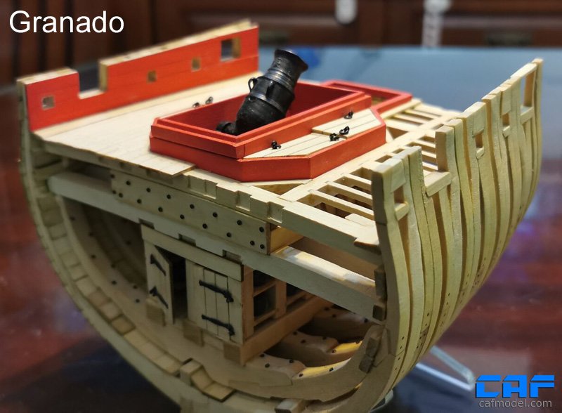
thibaultron Posted March 27, 2021 Author Share #3 Posted March 27, 2021 (edited) Part 001 I’m starting my build log of the CAF Models HMS Granado Cross-section in 1/48th scale (https://cafmodel.com/). This kit is a Plank On Frame with one side planked, and the other unplanked, to show all the frame/rib detail. CAF has a slightly different approach to the traditional (at least modern tradition) laser cut parts. Instead CAF CNC Mills the major components, allowing for better preshaping of the parts, for the modeler. Their site has more pictures of the completed model. The HMS Granado was a Bomb Vessel. Instead of a broadside of cannons, she was build with just a few defensive cannons and two large bore mortars set in wells on the deck. Regular cannon were setup for ship to ship engagements, and could not be elevated to any great degree. Thus ships of the line could not readily reduce a fortification, unless it was set at close to sea level, and even then they could mostly just attack the walls of the fort. The mortars on a bomb vessel however were designed to fire at high angles, allowing it to fire over the walls, into the interior of the fort itself. They were also of a much larger caliber than even a large broadside cannon. The mortar shells also had explosive charges to increase the damage. The bomb vessels were generally moored in place, out of the range of the fort, during action with anchor lines at the bow and stern. This allowed the ship to be turned to further zero in the targeting aim, and insured that once the range and target were attained, repeated fire would land in the same spot, rather than having to resight for every shot. The ship was defended from ships of the enemy fleet, by regular ships from her navy. To allow for a clearer field of fire the ships generally had two rather than the typical three masts, that a warship this size would carry. This model is of the larger of the two mortars, along with the cover for the well, used during sailing, to prevent water from filling the well from wave and rain. The cross-section includes the large deck support beams, and the racks the shot was stored on. Here is a photo showing a drawing of the completed model. The large box is fully packed with modeling goodies! One box contains all the hardware for the model, as well as hardware for the unique acrylic building frame. You build a box with supports for the frames and then assemble the model in this box, once all the individual frames have been assembled. The other box has all the acrylic pieces for the frame box. There is also a small sheet of photo-etched details. Included is a set of plans. These photos show the CNC milled wood parts. They are staying in the shrink wrap, and I will open them as needed during the construction. If you look closely you can see that some of the pieces have been milled on all sides to the correct shape. There will, of course, be more shaping on most of them, but a lot less than if you started with parts that were 2D laser cut on just two sides. Some of the flat parts are laser cut. The loop hanging down in this shot, is my camera strap, opps. The instruction book is a well detailed, illustrated step by step guide. It comes in a semi-bound clear binder. I proceeded to unbind it, by peeling off the cover, scraping the glue along the spine, and removing the staples. I’ll scan the whole book, so that I can print out each page, if any should get damaged during the build. I have more than once spilled glue or paint while building a model. I will also scan in the plans, for my own use only, so that I can print sections of the plans that you build various assemblies on top of. The frames, for example, are built on top of the plans. Edited March 27, 2021 by thibaultron typo Gus M, Matt D, mtaylor and 11 others 14 Ron Thibault Shipjack Carrie Price from Pyro kit, with upgraded detailing and history. Going From A 2D Drawing To A 3D Printed Part Tutorial Link to comment Share on other sites More sharing options...
Gus M Posted March 27, 2021 Share #4 Posted March 27, 2021 great, looking forward to seeing the development of your work Old Collingwood, mtaylor, Canute and 1 other 4 Greetings Gus ------------------------------------------------------------------- Current build log: San Francisco Cross Section Link to comment Share on other sites More sharing options...
ringleheim Posted March 29, 2021 Share #5 Posted March 29, 2021 I have just come to know of this kit in the last 24 hours or so, and am wandering around the internet trying to learn everything I can about it. I will be following your build here with keen interest! Old Collingwood, Canute, thibaultron and 1 other 4 Link to comment Share on other sites More sharing options...
thibaultron Posted April 9, 2021 Author Share #6 Posted April 9, 2021 Part 002 I did some prep work over the last couple days. I’ve scanned in the frame drawings, so I can print out each as I’m working on that frame. When you build the frames, there are spacers that have to be glued to the plans, so I want to have the printouts, to glue to, rather than the plans sheet. I bought new 5” sanding disks, and new belts for my Delta belt/disk sander. I had a hard time locating them in Home Depot, as the vast majority of the sanding disks, are for the newer tools that mount them using hooks, rather than self sticking ones. They were buried up in one corner, with about 10 times the selection of the hook types. The selection was also limited, the 120 and 220, were the finest grits they had. The belts were also limited to the one package with the three grits shown. I used Goof Off to clean the surface of the aluminum disk, so the new disks would sit flush. I also pulled out the small parts, and I’m glad I did! The bag holding the 20 cannon balls had ripped, and several were floating around the parts box. If I had not noticed this, some of them may have gotten lost as I progressed. As it was, one of them fell out of the bag and rolled off the workbench! As it turned out, it ended up stuck between the back and cushion of my chair. I retrieved it before it fell between them, which was good, as the area under the seam is sealed, and I would have never found it, if it had fallen in. I put the brass balls in a small jewelry can I had, and separated the bags of screws for the frame box, into separate cans as well. I was pleased to see that each of the three screw types, were in separate bags, not jumbled together. The three bags were stapled to one label. I then placed the cans and parts bags into a clear plastic compartment box. Not a lot of progress, but it has been a busy few days for me, so I’m happy to have made some progress. The ripped cannon ball bag, and the label for the screws. The small jewelry cans with the screws and brass balls. The parts in the container. In addition to these, there are the 3D printed corners for the frame box, which were too big to put in this box. Looking at these pictures, reminds me that I have to dig the PE fret out of the box, and put it in a container too, before it gets lost, or bent. Canute, Matt D, hamilton and 4 others 7 Ron Thibault Shipjack Carrie Price from Pyro kit, with upgraded detailing and history. Going From A 2D Drawing To A 3D Printed Part Tutorial Link to comment Share on other sites More sharing options...
thibaultron Posted April 11, 2021 Author Share #7 Posted April 11, 2021 Part 003 Finally got started on the actual model today. I printed out the frame drawing scans, one per sheet, onto cardstock. I measured to make sure the size was correct, then taped the sheet for Frame 6 onto the glass sheet on the workbench. I went through the wood sheets, until I found the two shims needed for this frame. They glue at the tops of the frame drawing. I brushed some glue onto them, put them in place then put weights on each to keep them flat, while it dries. I’ll go back, hopefully, tomorrow, and start on the actual frame construction. hamilton, Canute, EricWilliamMarshall and 7 others 10 Ron Thibault Shipjack Carrie Price from Pyro kit, with upgraded detailing and history. Going From A 2D Drawing To A 3D Printed Part Tutorial Link to comment Share on other sites More sharing options...
thibaultron Posted April 24, 2021 Author Share #8 Posted April 24, 2021 Part 004 Got a little accomplished today. I took the weights off the frame sheet, and the shims had glued down nicely. To prevent the frame pieces from sticking to the shims and frame sheet, I was going to used wax paper, but decided that it was both too thick, and opaque, for the job. Instead I used Scotch tape. First I put a long piece the length of each shim, then cut carefully around the bottom of the shims, pushing the tape end down onto the paper, covering the area that the chucks will sit down on. Then I covered the rest of the bottom of the frame area, leaving a good length sticking up on the ends. I then cut across where the bottom tape crossed over the pieces left from covering the shims. Then, I pulled the cut ends off, leaving only a short area where the taped was double thickness. I noticed that the sheet was not completely flat near the top, so I placed a weight across that area. The parts numbering was a bit confusing, at first, until I examined the parts sheets. 5F-6B4- For instance translates as, Parts Sheet 5F part 6B-4, as shown in the parts diagrams in the book. This picture also shows one of the reasons I scanned the instructions. As I find and remove the parts, I highlight them. As I progress, this will make finding the parts easier, by process of elimination. It will also, hopefully prevent me from ending up with parts left over, when I finish! I still have to cut out the rounded areas left when the parts were CNC routed, so I’ve only cut out the three parts highlighted. I have to figure out how to mount my lighted magnifier lamp “eyes” to the new work bench, as I had to leave off the built in vise at the right hand end, now that the spray booth sits there. The workbench top is too thick, to mount the factory “C” clamp. I’m using a second compartmented box, like the one I put the small parts in , to store the frame pieces, while I’m assembling them, or when I finish for the day. After some consideration I decided that I needed to be able to pin the frame sections in place while the glue dries, so I need to move the frame drawing from the glass plate to a wood base. I did not have any wood that was flat enough for my satisfaction, so I needed to buy another piece. The best type of wood to insure flatness, is butcher block types. I went to Home Depot, and found a 17.5”X 1” thick disk butcher block piece. Even then most of them were far from flat. I went through them and only found three of a dozen or so, that were close to flat. I selected the one that was the flattest, and bought that one. It is still a little bowed, but very close to dead flat, and close enough for this application. So I transferred the frame drawing from the glass to the disk. I also bought a short MDF shelf, that I will cut into sections, and glue sandpaper to. This will give me nice flat surfaces to sand “stuff” on. Canute, Matt D, mtaylor and 8 others 11 Ron Thibault Shipjack Carrie Price from Pyro kit, with upgraded detailing and history. Going From A 2D Drawing To A 3D Printed Part Tutorial Link to comment Share on other sites More sharing options...
Canute Posted April 24, 2021 Share #9 Posted April 24, 2021 Ron, some good ideas for ensuring flatness. I've been fortunate to have a friend who repaired copiers/printers once upon a time. He gave me some of the glass plates from the tops of these machines. They're flat plate glass and the edges are protected. I keep one for gluing various sand paper grits to and use the other as a build board, if I don't need to pin parts. Edwardkenway, EricWilliamMarshall, CiscoH and 4 others 6 1 Ken Started: MS Bounty Longboat, On Hold: Heinkel USS Choctaw paper Down the road: Shipyard HMC Alert 1/96 paper, Mamoli Constitution Cross, MS USN Picket Boat #1 Scratchbuild: Echo Cross Section Member Nautical Research Guild Link to comment Share on other sites More sharing options...
thibaultron Posted April 24, 2021 Author Share #10 Posted April 24, 2021 The glass sheet I originally had the drawing taped to is a thick (~10"X 3 foot) plate glass shelf, I found at a thrift store. I wish I'd had the money to buy the other ten or so they had! mtaylor, Canute and Old Collingwood 3 Ron Thibault Shipjack Carrie Price from Pyro kit, with upgraded detailing and history. Going From A 2D Drawing To A 3D Printed Part Tutorial Link to comment Share on other sites More sharing options...
thibaultron Posted June 17, 2021 Author Share #11 Posted June 17, 2021 Part 005 Now that I have finally gotten my workshop back into some semblance of order, I got back to the Granado! I bought a new work bench from Home Depot that cranks up and down. Removing the Harbor Freight work bench I’d just installed, took some work. I started by mounting the frame drawing from the last part of the build onto the circular butcher block disk, and taped a piece of sand paper to the paper to use for sanding pieces, as needed. The first thing I found was that the butcher block was much too tough to insert pins into! So back to the drawing board. I bought a piece of ¼” X 4” x 24” basswood from Hobby Lobby, to use as a pin pad. I found some ½” cove molding in my shop, and framed the new “Pin Friendly” area with it. The area is 11 ½” x 8”. In retrospect, I should have gone with 11 ¾”. Just to allow for a little more area for the non-paper side of the hold down tape. I started with the bottom piece of the cove molding, cut to 12 ½”. The only finish nails I had in the shop were #6 x 2” ones, so I used those. #4 would have been better. I predrilled the molding in three places, using a 5/64” drill. The molding was put in place, and the first nail hole drilled into the base, then the molding itself was drilled out with a 3/32 drill. With the first nail temporarily installed I drilled the other two holes, in the same manner. I then removed the molding applied glue, and reinstalled it. Next a piece of molding about 7 ½” long was attached in the same way on one side, using a square. I cut it to 7 ½” instead of 8” for two reasons. The first was that it allowed a little wiggle room , if the basswood was not quite 4” wide, or I cut the molding too long. The second was so I have someplace to get under the basswood, in the future, when I need to replace it, due to too many pin holes. I cut the basswood in half, then clamped the two pieces together, and cut both at the same time, to insure that they were the same length. With the first two molding pieces in place, I placed the basswood on the base, and installed the top 12 ½” top piece tight against the basswood pieces. After gluing the top piece on I cleaned up the glue seepage, and allowed a few minutes for the seepage area to dry. Now with the basswood reinstalled, I installed the right hand side piece, again tight against the basswood. Once again I cleaned up seepage after gluing the last piece of molding, and allowed some drying time. At this point the base and frame looked like this. This picture shows the basswood temporarily installed to test the fit. Next I used a Dremel cutoff wheel to trim the protruding nails and cut and filed the ends of the molding to match the curve of the side pieces. Next I cut the top of the ½” molding down to level or slightly below the top of the basswood, when installed. If I had been thinking, I should have run the molding through the saw, to trim this, before I started! A sharp chisel did the honors though. Then I sanded the cuts with a sanding block. Next I installed the basswood. Due to pushing the molding tightly against the blanks, when installing the molding, the basswood pieces are held in place by friction, so I can pry them out for replacement, in the future. The frame sheet was then retaped in place, and I could finally start frame 6! The basswood holds the pins well. ½” basswood might be better, but Hobby Lobby only had 3” wide pieces of that in stock. I’ll have to be a little more careful with the fit of the parts in the future, as the camera shows the parts are not as well fitted as I thought when I glued the parts together. After I finish this frame, I’m going to run the round base through my table saw, and cut off the bottom of the round, even with the molding, this will allow me to get the base closer to the table edge, when working on the frames. This setup should work for many future models, as well as this one, and will be a basis for a future building board for my balsa, and Model Expo plane kits. hamilton, EricWilliamMarshall, Ryland Craze and 6 others 9 Ron Thibault Shipjack Carrie Price from Pyro kit, with upgraded detailing and history. Going From A 2D Drawing To A 3D Printed Part Tutorial Link to comment Share on other sites More sharing options...
thibaultron Posted June 21, 2021 Author Share #12 Posted June 21, 2021 Part 006 I continued on with building Frame 6, by assembling the other upper timbers, on the other side. A warning note: The instructions call both upper timbers Part 5F-6B-6 but those parts are mirror images of each other, so look carefully at the drawing in the instructions, to make sure you are putting them in the correct position. The carved surfaces are installed facing up. I continued by assembling the bottom sections of the frame. Note two mistakes I made. First, I should have left the frame in place, as the next step is to build the other half of the frame on top of this section. Luckily I did make the first mistake, as when I went to put the frame back in place. I found that the lower half would not fit back on the sheet! It was too wide to fit between the two shim pieces! Tomorrow, I will get some Isopropyl Alcohol and soften the glue between the chocks and the upper halves of the frames. After I trim the beam ends so all will fit where they should, I’ll fix this. From now on I will build the bottoms of the frames first. Jack H, Canute, JeffT and 2 others 5 Ron Thibault Shipjack Carrie Price from Pyro kit, with upgraded detailing and history. Going From A 2D Drawing To A 3D Printed Part Tutorial Link to comment Share on other sites More sharing options...
thibaultron Posted June 25, 2021 Author Share #13 Posted June 25, 2021 Part 007 Well two steps forward and one back, a little better than the other way around. As I mentioned last time, Frame 6 would not fit back between the shims when I tried to put it back into place. The only solution was to unglue all the parts (I found a couple other mistakes, and will correct them all at once), and start over with building it. I softened the glue joints (Elmers) by soaking them with 90% Isopropyl Alcohol. To do this I held the joint over a plastic tray and dribbled the alcohol over the joint using a pipette. I’d dribble a little on, let it soak in, then turn the frame over, and hit the other side. I’d wait a few seconds and do it again. I generally did this 3 or 4 times. After allowing a minute or so I’d try the joint, and continue if it wouldn’t separate under moderate pressure. Most of the joints yielded after a couple of tries, but some took 5 to 10 minutes of effort. When a joint would separate, I then scraped it with my fingernail to get as much of the glue off as I could. I’m letting the pieces dry for a few days, and will start over. EricWilliamMarshall, Matt D, Old Collingwood and 3 others 6 Ron Thibault Shipjack Carrie Price from Pyro kit, with upgraded detailing and history. Going From A 2D Drawing To A 3D Printed Part Tutorial Link to comment Share on other sites More sharing options...
Matt D Posted June 26, 2021 Share #14 Posted June 26, 2021 It looked like it was going so well. Do you know what went wrong? Canute, thibaultron, mtaylor and 1 other 4 Current Build: HMS Winchelsea 1:48 (Group Project) Completed Builds: Virginia 1819 Artesania Latina - 1:41 Link to comment Share on other sites More sharing options...
thibaultron Posted June 26, 2021 Author Share #15 Posted June 26, 2021 I should have started with the bottom parts, and fit them between the shims, then built the upper sections. hamilton, Old Collingwood, Matt D and 1 other 4 Ron Thibault Shipjack Carrie Price from Pyro kit, with upgraded detailing and history. Going From A 2D Drawing To A 3D Printed Part Tutorial Link to comment Share on other sites More sharing options...
thibaultron Posted July 30, 2021 Author Share #16 Posted July 30, 2021 Part 008, or “How to continue to do it wrong!” During the build, I will continue to show mistakes, why I made them, and (Hopefully) how I fixed them. This is my first POF build, and basically my first wood sailing ship kit, though I have built HO scale wood buildings and wood RC warships. By showing my mistakes, I may help others avoid them. “Good judgement comes from experience, experience comes from bad judgement. " In retrospect, I should have started with one of the inside frames, where mistakes could have been more easily hidden. As I mentioned before, Frame 6 would not fit back between the shims when I tried to put it back into place. After getting everything un-glued, I rebuilt the lower section of the frame first, so far so good. Then, I said to myself, “Self, you know this frame has to fit onto the keel, doesn’t it?”. Self replied, “You’re right, better try that!" So I found the two pieces for the keel, the keel, and false keel. The first thing I found was that both pieces had been machined incorrectly!! As you can see above, the blank apparently shifted a little when they turned it over to mill the back, and the upper and lower surfaces came out misaligned. Not by much, but after cleanup both the parts were too short by twice the difference in misalignment (had to correct both top and bottom). At least the relative depth of the lands on the false keel are correct. So, I thought, “I can just add a shim between the keel and false keel, to make up the difference.” Looking at the keel. I then discovered that the two rabbets are now also misaligned, height wise, and the keel will sit lower in the assembly jig. Not good! I’m going to write to CAF, and see if they will replace these two parts. Luckily, these were the only parts in that blank. After some cleanup it looked like this, Now, to continue the frame 6 story, it turns out that, no, the keel would not fit in the frame slot! ********!! I tried widening the slot with files, etc., but was just marking up the underside of the chock, and cutting the frame piece unsquarely. So, out came the Isopropyl alcohol again! I cleaned up the unsquared area with my disk sander and got everything put back together, with the keel now fitting nicely. Then, for fun, I cutout the bottom piece of the upper half of the frame, and placed it on top of the lower pieces. Double *******! The lower frame curve was too shallow! So once again, do over. If you look closely you can see that the front assembly, does not have the same curve as the back piece (6A-6A-1). Note however how nicely the edges of the wider sections match. Sigh. I cleaned up the outside surfaces of the upper piece to remove the attachment points. As can be seen in the above picture, I then applied tape to the mating surface of the part, to prevent it from sticking to the lower pieces. Then I glued the lower pieces in place and clamped the upper piece in place to align them. I had to sand the wedge areas of the chock to lengthen it to fill the longer gap between the two frames. There is enough meat in the part to do this. After everything was correctly positioned I clamped the upper section to the lower ones, until the glue had grabbed, then removed the upper section, and placed a weight on the lower parts, to keep them flat. Finally I got the two curves to match, unfortunately, now the keel slot in the bottom half is too wide. Also unfortunately this frame is an end frame, and, naturally, the exposed side. I’ll figure out that problem later. Here is a picture with the bottom section glued back together, and the upper piece set on top. Now the curves match! And, also now, the slots in the lower half are wider than the ones in the upper section. After everything had dried, I glued the rest of the lower Frame 6 parts in place. Finally done with this assembly! JeffT, Old Collingwood, coxswain and 3 others 6 Ron Thibault Shipjack Carrie Price from Pyro kit, with upgraded detailing and history. Going From A 2D Drawing To A 3D Printed Part Tutorial Link to comment Share on other sites More sharing options...
hamilton Posted July 30, 2021 Share #17 Posted July 30, 2021 Wow - the time, trouble and revision was definitely worth it - for these result and I imagine for all the other frames you'll have to assemble! Looking forward to watching this one come together - I saw another one of these from an MSW member and can't recall who, unfortunately (sorry to you if you're reading this!) and it builds into a really nice model. Have fun! hamilton thibaultron, Old Collingwood and EricWilliamMarshall 3 current builds: Corel HMS Bellona (1780) previous builds: MS Phantom (scuttled, 2017); MS Sultana (1767); Corel Brittany Sloop (scuttled, 2022); MS Kate Cory; MS Armed Virginia Sloop (in need of a refit); Corel Flattie; Mamoli Gretel; Amati Bluenose (1921) (scuttled, 2023); AL San Francisco (destroyed by land krakens [i.e., cats]); Corel Toulonnaise (1823); MS Glad Tidings (1937) (in need of a refit); HMS Blandford (1719) from Corel HMS Greyhound; Fair Rosamund (1832) from OcCre Dos Amigos (missing in action); Amati Hannah (ship in a bottle); Mamoli America (1851); Bluenose fishing schooner (1921) (scratch) under the bench: Admiralty Echo cross-section; MS Emma C Barry; MS USS Constitution; MS Flying Fish; Corel Berlin; a wood supplier Colonial Schooner Hannah; Victory Models H.M.S. Fly; CAF Models HMS Granado; MS USS Confederacy Link to comment Share on other sites More sharing options...
Richard44 Posted July 30, 2021 Share #18 Posted July 30, 2021 I'm following your build with interest Ron, as it's a kit I may buy myself at some time. thibaultron and Old Collingwood 2 Richard Next build: Completed builds: AL's Endeavour, Corel's Bellona, Amati's Xebec, Billing's Roar Ege, Panart's Armed Launch Ships' Boats - Vanguard 1:64 and Master Korabel 1:72 Alexander Arbuthnot, Christiaan Brunings, Pevensey all by World of Paperships HMS Pegasus by Victory Captain John Smith's Shallop by Pavel Nitikin Rumpler "Taube" 1911 by HMV Link to comment Share on other sites More sharing options...
thibaultron Posted August 1, 2021 Author Share #19 Posted August 1, 2021 Part 009 Next I had to clean out the inside corners of the upper piece for the slots for the false keel, keel, and chocks, to remove the rounded corners left by the milling bit. After further cleaning up the false keel, I used it and the keel to check my progress on cutting out the corners. Next I used the false keel as a jig to align the upper and lower frame slots, and glued the upper section in place, then removed the false keel and placed weights on the upper section and along the exposed lower half to keep everything level while the glue dried. Next came a step that should have been in the instructions, before the frame assembly. There is a temporary resin fill piece between the upper and lower halves of the frame, that positions the upper tips of the frame pieces, away from each other. After the frame is glued, two small pieces of wood span areas of this gap, and form part of the finished frame. The only reference to this is the graphic of assembling the upper half, were it is shown in place between the frame sections. This shows the two pieces that will be installed when the inserts are removed. The entire upper tip piece will stand proud, of the lower frame half, held in place only by the chock and the two inserts, once the frame is finished. After I install the two wooden support pieces, I’ll trim the head off the insert, and reinstall the tail piece, to support the gap, until I reach a point where it is no longer needed. The problem, is that both the upper and lower tip pieces have to be fitted to the resin piece, just like the chocks and keel parts. With the lower half assembled this proved awkward. One thing to be aware of, is that the groves are angled, not straight across the frame section. Yes, I didn’t notice this on the first two pieces. The resin piece required minor cleanup to remove some small vent nubs along the flat tail piece. This is a picture of one side cut to fit the insert, and the other before I started. Here is both sides fitted. Notice that the lower frame half tip (the upper one in this shot) “re-kitted” itself during the process. The same thing happened on the other side. So, after fitting the parts, I reattached the two lower frame pieces, and, after the glue dried, proceeded to glue one of the upper pieces in place. I shortened the tail piece of the resin spacer a little, to make sure that it was not hitting the adjacent frame section. I found that modified clothes pins had just the right spacing to clamp the parts parallel. I reversed the spring so that the handle ends were the side closed by the spring pressure (see the photos). I used a clamp on either side of the chock, and at the top of the frame to hold the tips in line. I used a file to add weight to hold the tips tight to the insert. This method does not normally work on a single chock holding two frame sections as the pressure tends to push the parts away from each other. For this use though, everything is locked in place by the insert and the previously glued sections, and the clamp ends are spaced by the lower frame surfaces. Yes, the third photograph shows a nice lump of excess glue at the chock, but that end of the chock will be filed down to match the frame section, which is thinner than the mating end of the tip piece. If you look at the joint to the right in that picture, you will see that the same thing will have to be done to one side of that chock, also. The forum software only allows a maximum of 16 pictures per post, so I will continue when I get a bit further along is completing this frame. dvm27, Matt D, CiscoH and 7 others 10 Ron Thibault Shipjack Carrie Price from Pyro kit, with upgraded detailing and history. Going From A 2D Drawing To A 3D Printed Part Tutorial Link to comment Share on other sites More sharing options...
coxswain Posted August 1, 2021 Share #20 Posted August 1, 2021 You're doing a great job here Ron, and a great service to 'less experienced' wood modelers (such as myself)! Really appreciate your taking the time to show each step with detailed explanations and professional diagrams. Steve M Old Collingwood and thibaultron 1 1 Link to comment Share on other sites More sharing options...
thibaultron Posted August 19, 2021 Author Share #21 Posted August 19, 2021 Just remember, I'm one of the "less experienced" ones too. coxswain 1 Ron Thibault Shipjack Carrie Price from Pyro kit, with upgraded detailing and history. Going From A 2D Drawing To A 3D Printed Part Tutorial Link to comment Share on other sites More sharing options...
thibaultron Posted August 19, 2021 Author Share #22 Posted August 19, 2021 Part 010 Next I removed the resin inserts and trimmed off the heads, then reinstalled the tail pieces. I installed the larger of the blocks that tie the tips of the two halves together. Then I installed the thin piece, that goes below it. This is a laser cut plywood piece, and I had to sand bevels on each end so that they could slide into the groves in the frame. At this point I noticed that I had not sanded them enough and they had spread the frames a little (see the above picture). By that point, however, the glue had dried enough to prevent me removing them! I’ll have to break out my Jewelers Saw and cut through the center, which will hopefully remove enough so that the frames close up properly. Meanwhile, I cut the chocks down to match the level of the respective frame members. The photograph shows one chock cut and sanded (right hand side), while I have just started on the second one. For this I used an X-Acto Number 2 blade, small files, and fingernail sanding sticks. After the chocks passed the fingernail test (a fingernail passed across the surface does not catch on any protrusions at the joints of the surfaces), I sanded along the grain to hide the marks made cutting out the piece. After finishing the chocks on this side, I flipped the frame over and did the same to the ones on that side. I then used the saw to split the plywood pieces, On one side the plywood fell out as I was completing the cut. I glued the two sections back together and reinserted them. In the picture below you can see them right after I got them back in. I took a pair of flat surface needle nose pliers and used them to hold the two plywood sections into a flat alignment top and bottom (you can see that they are not aligned in the picture above). Once the glue had dried I faired the ends of the plywood pieces and the blocks above them down even with the frame surfaces. I also filed the top and bottoms of the plywood inserts to insure that those surfaces were lined up correctly. I managed to pop one of the other joints in the frame while doing this, but in the end, I finally finished this frame! Next I started to look around for something to store the frames in, as I finished them. In the end I found a simple, cheap, way to do this. I had a beat up one of the small Post Office Flat Rate Boxes laying around and when I folded it up, it was an ideal size. The box is designed to be held together, once folded up, when the tab on the top is glued to the front of the box. As I was going the not glue the top down, I glued the corner tabs in place then folded the side ears down and glued them also. After cutting the ears off the sides of the top, I had a nice frame holder! It is large enough to hold two frames in each layer, if the second frame is set in upside down so that the bottom of the frame spans over one tip of the first. It looks to be deep enough for three layers (6 frames total) of frames per box. At this point, in time, I have also finished Frame 7, and will detail that in the next part. Before starting on the next two frames (7 & 8), there are corrections to the instructions needed, so stay tuned, (or go to John H’s review of this kit, where he details the corrections)! BobG, HardeeHarHar, gjdale and 9 others 12 Ron Thibault Shipjack Carrie Price from Pyro kit, with upgraded detailing and history. Going From A 2D Drawing To A 3D Printed Part Tutorial Link to comment Share on other sites More sharing options...
thibaultron Posted September 29, 2021 Author Share #23 Posted September 29, 2021 There will soon be more updates. My time lately has been taken up with preperations for and the actual surgery my wife needed. I am also having problems sitting at my computer due to pain from my bad hip. I've completed two more frames, and have the photos, but have not been able to do the writeups, yet. Hang on and more parts will be posted soon. mtaylor, Old Collingwood and EricWilliamMarshall 1 2 Ron Thibault Shipjack Carrie Price from Pyro kit, with upgraded detailing and history. Going From A 2D Drawing To A 3D Printed Part Tutorial Link to comment Share on other sites More sharing options...
mtaylor Posted September 30, 2021 Share #24 Posted September 30, 2021 I'm sorry to hear of the health issues, Ron. I hope her surgery goes well. We are a patient lot so no rush. EricWilliamMarshall, Old Collingwood and thibaultron 2 1 Mark "The shipwright is slow, but the wood is patient." - me Current Build: Past Builds: La Belle Poule 1765 - French Frigate from ANCRE plans - ON HOLD Triton Cross-Section NRG Hallf Hull Planking Kit HMS Sphinx 1775 - Vanguard Models - 1:64 Non-Ship Model: On hold, maybe forever: CH-53 Sikorsky - 1:48 - Revell - Completed Licorne - 1755 from Hahn Plans (Scratch) Version 2.0 (Abandoned) Link to comment Share on other sites More sharing options...
thibaultron Posted September 30, 2021 Author Share #25 Posted September 30, 2021 She had her surgery last week, and is recovering well, thanks. HardeeHarHar, mtaylor, Rustyj and 3 others 5 1 Ron Thibault Shipjack Carrie Price from Pyro kit, with upgraded detailing and history. Going From A 2D Drawing To A 3D Printed Part Tutorial Link to comment Share on other sites More sharing options...
thibaultron Posted October 1, 2021 Author Share #26 Posted October 1, 2021 Part 011 First here is a picture of two of the frames nested in the small box, as I mentioned in the last post. Yes, that second frame is Frame 7, finished. This one should be able to hold another layer of frames. Back to the construction of Frame 7. Once again I started by taping down the frame drawing I printed on cardstock after scanning the drawing in from the plans (a good choice as described below). Then I glued down the upper frame shims, and applied clear tape over the drawing areas, to keep the frame parts from sticking. Note: that the drawing for Frame 7 shows that the upper half of the frame (Black) is shown offset slightly higher than the lower (Red), I missed this, but there is enough meat on the frames that sanding can correct this. When cutting out the frame pieces, I hit upon an idea. One of the standard ways of filling gaps, is to mix sawdust with the glue you are using, and there is a lot of sawdust left between the parts and the carrier sheets. I had been throwing this away, but now I free the parts over a piece of paper and sweep them into a small container, for later use. I decided to build this frame differently than the first. Instead of building the first layer, complete with chocks, I built it by gluing the mating ends of the frame pieces together before hand. I did glue in the keel chock with the lower frame, as this set the gap to fit over the keel. The reason I did this was there were gaps between the mating ends of the frame sections on Frame 6, where I didn’t trim the length of the chocks correctly. Everything looked good when it was on the drawing, but they were noticeable once I removed it. I also, with this frame, started building the upper frame half on top of the lower as I worked up the frame. This insured they were both following in line, unlike the problems I had with the lower frame not lining up with the upper, on Frame 6. As I would span a chock space with an upper frame section, I would go back and remove the frame and fit the chock in, after the glue on the frame section had dried. This gave me tighter joints between the frame section ends. I generally let the glue set overnight, and it was at this stage when I decided that, while the glue dried, I’d build a simple plastic model between gluing. This worked well, until I knocked over the plastic glue bottle onto the frame at the above completion level!! I can report that Elmer’s will stand up to being soaked with plastic glue, at least the brand I use! The cardstock frame drawing, not so much! I had to remove the drawing scrape the paper off the shims, and glue them down to a new copy of the drawing. At this point I forgot to put the clear tape down, and had to carefully separate and clean the frame, the next time some glue got between it and the frame. Sigh. After this fiasco I continued building the frame. Here and on the other side, I did glue in the chock to make sure it fit in the notch of the shim piece. The blocks used for weights below, are cheap (at least 20 or so years ago) 123 machining blocks. The 123 blocks are 1”X 2”X 3” blocks that are a standard part of machining setup pieces. Normal 123 blocks are drilled and sometimes tapped in several places, hardened steel blocks used to insure your work piece is set squarely in place for machining. These are a cheap set with only the one hole. The tip sections of the upper and lower haves sit against each other, with no resin spacer, like those used for frame 6 During the construction, I had a labor dispute with some ants as to who the workbench belonged to, and had to settle the disagreement with Extreme Prejudice! The finishing of this frame and the start of Frame 8 will continue in the next part. JpR62, gjdale, HardeeHarHar and 5 others 8 Ron Thibault Shipjack Carrie Price from Pyro kit, with upgraded detailing and history. Going From A 2D Drawing To A 3D Printed Part Tutorial Link to comment Share on other sites More sharing options...
mtaylor Posted October 1, 2021 Share #27 Posted October 1, 2021 Looking great, Ron. As for the ants... to me "extreme prejudice" involves fire. Not a good thing in the shipyard. Old Collingwood and thibaultron 2 Mark "The shipwright is slow, but the wood is patient." - me Current Build: Past Builds: La Belle Poule 1765 - French Frigate from ANCRE plans - ON HOLD Triton Cross-Section NRG Hallf Hull Planking Kit HMS Sphinx 1775 - Vanguard Models - 1:64 Non-Ship Model: On hold, maybe forever: CH-53 Sikorsky - 1:48 - Revell - Completed Licorne - 1755 from Hahn Plans (Scratch) Version 2.0 (Abandoned) Link to comment Share on other sites More sharing options...
JeffT Posted October 1, 2021 Share #28 Posted October 1, 2021 Just curious, how are you scanning the frame drawings? thibaultron, mtaylor and Old Collingwood 3 Jeff In progress: Medway Longboat 1742 - Syren Ship Model Company -1/2" scale USS Constitution - Model Shipways - Scale 1:76 HMS Granado - CAF Model - 1:48 HMS Sphinx - Vanguard Link to comment Share on other sites More sharing options...
thibaultron Posted October 2, 2021 Author Share #29 Posted October 2, 2021 Flatbed scanner. I hold the area to be scanned and place a book on it to hold it flat. Old Collingwood, mtaylor and JeffT 3 Ron Thibault Shipjack Carrie Price from Pyro kit, with upgraded detailing and history. Going From A 2D Drawing To A 3D Printed Part Tutorial Link to comment Share on other sites More sharing options...
mtaylor Posted October 2, 2021 Share #30 Posted October 2, 2021 If you haven't done this, I urge you to.... Test the scanners/printers against the original. Scanners and printers for a long time have not done exactly 100% copies. They're off by as much as 2-3% for each machine to prevent counterfeiting of money. I've run into this in the past and now use a local architectural print service. JeffT, coxswain, thibaultron and 1 other 4 Mark "The shipwright is slow, but the wood is patient." - me Current Build: Past Builds: La Belle Poule 1765 - French Frigate from ANCRE plans - ON HOLD Triton Cross-Section NRG Hallf Hull Planking Kit HMS Sphinx 1775 - Vanguard Models - 1:64 Non-Ship Model: On hold, maybe forever: CH-53 Sikorsky - 1:48 - Revell - Completed Licorne - 1755 from Hahn Plans (Scratch) Version 2.0 (Abandoned) Link to comment Share on other sites More sharing options...


Recommended Posts