Boccherini Posted October 13, 2022 Author Share #121 Posted October 13, 2022 (edited) Wefalk, thanks for the details, I'll keep them in mind when working small dia wire. The profile was used to form the balustres (thanks for the correct terminology). The under side of the profile is the cutting edge. The profile is sitting on top of a tool in the post, which gives it the correct height. Like you, I'm lazy, removing/replacing tool posts is a pain. Fortunately, the cross slide is large enough to accommodate this arrangement. Roger, thanks for your two bob's worth. I agree, the metal belaying pins are better. Grant. Edited October 13, 2022 by Boccherini wefalck and Roger Pellett 2 Quote Link to comment Share on other sites More sharing options...
Boccherini Posted October 14, 2022 Author Share #122 Posted October 14, 2022 Top Rails: using the lower rail as a template was a failure. My construction skills are not sufficiently accurate. I ended up pinning thin card to the centre ballustre at the stern, and the port and starboard ones at the other end, then marked out the ballustre tops on the underside of the card and created the template from that. The template was copied onto transparency film and pinned onto the ballustres with some thin card under to provide support. Constructing the rail on top of the ballustres allowed me to "bake" the sweep of the sheer into the rail. The rail was made with from two parts laminated together, with the scarfed joints of the top piece, half way between the lower joints. The sections were weighted down whilst the glue dried. The top scarfs were dowelled through to the underside of the lower half. After the pva had set, the rail was dowelled with copper wire and epoxy into the ballustres. The ballustrade across the front of the poop deck was constructed in a similar fashion. I apologize for the lack of (detailed) pictures, the process completely consumed me for a couple of weeks. It's not perfect, but I'm content with the finished product. Grant. ccoyle, Tony Hunt, Vladimir_Wairoa and 3 others 6 Quote Link to comment Share on other sites More sharing options...
Tony Hunt Posted October 14, 2022 Share #123 Posted October 14, 2022 "It's not perfect, but I'm content with the finished product." So you should be! It looks really good. Quote Link to comment Share on other sites More sharing options...
Boccherini Posted October 15, 2022 Author Share #124 Posted October 15, 2022 Tony, thanks for the encouragement. Poor old Harriet has so many errors and miss steps, I may have to change her name to: "Barque (circa 1860)". Grant. Quote Link to comment Share on other sites More sharing options...
Boccherini Posted October 18, 2022 Author Share #125 Posted October 18, 2022 Wheel: Thanks to Ed Tosti and his most excellent tutorial. I had to make a rod to work from, the MF70 only has a 3 jaw dividing head. The first attempt was a disaster, due to forgetting the grain direction is quite important. I changed tack, and glued 2 thin, square pieces with the grain at 90 degrees, then glued that piece to the end of the rod. Amazingly, it didn't drop off until after the wheel had been separated. The square addition was rounded, then the wheel parts cut out and drilled. The easiest way to make the spokes was with a drawplate, glued in, and the wheel cut off. The first and second attempts side by side. Grant. Roger Pellett, Ian_Grant, KeithAug and 9 others 9 3 Quote Link to comment Share on other sites More sharing options...
wefalck Posted October 18, 2022 Share #126 Posted October 18, 2022 Excellent approach! Some people also glue sections tangentially and cut to form a hexagon, or rather two hexagons offset by 30° for added strength, to better represent full-scale practice. Quote wefalck panta rhei - Everything is in flux Link to comment Share on other sites More sharing options...
Vladimir_Wairoa Posted October 18, 2022 Share #127 Posted October 18, 2022 fantastic detailed work. Quote Link to comment Share on other sites More sharing options...
Tony Hunt Posted October 18, 2022 Share #128 Posted October 18, 2022 I can see that I really must buy myself a milling machine... 😃 Quote Link to comment Share on other sites More sharing options...
Boccherini Posted October 19, 2022 Author Share #129 Posted October 19, 2022 Thanks Wefalk. Your suggestion is noted. I think it may not have been practical in this instance, the outside diameter of the wheel is a smidge over 19mm. Thanks Vladimir. Tony, they are a useful addition to the workshop. I've certainly had no regrets purchasing the Proxxon, it has done all that I've required of it. The only downside so far........it's quite noisy. Grant. Quote Link to comment Share on other sites More sharing options...
wefalck Posted October 19, 2022 Share #130 Posted October 19, 2022 It's noise only, I suppose, when you are milling wood at high-speed. When milling metal, you work at much lower speeds and hence less high-pitched noice. Quote wefalck panta rhei - Everything is in flux Link to comment Share on other sites More sharing options...
Boccherini Posted October 19, 2022 Author Share #131 Posted October 19, 2022 (edited) Wefalk, it appears to be mostly motor noise. Wheelhouse: The "carcass" is constructed from 3mm ply with whatever was lying around to cover the top. A pear veneer was glued on with pva. Normally, I would've used contact cement, but a brief internet search brought about a change of glue. This appears to be a better method. It requires pva to be placed on the surface to be veneered only and quick, moderate clamping before the veneer starts curling. The reason for using milled slots for the corners and sides: guaranteed vertical timbers. I've found gluing thin strips difficult to correctly locate and the strips are prone to "random movement" while placing weights on top. The rest is just sticking bits of wood on until it's completed. I may sand the roof and paint it to mimic actual practice......or not. That is about where I'm currently at. Grant. Edited October 19, 2022 by Boccherini Rudolf, Prowler901, Glen McGuire and 3 others 4 2 Quote Link to comment Share on other sites More sharing options...
wefalck Posted October 19, 2022 Share #132 Posted October 19, 2022 Looks actually very nice! Ship-shape, Bristol-fashion! For me PVA (white gule) would be the standard glue for wood and I would rather not use contact cement. The latter, due to its high viscosity, sits on the wood surface, while PVA 'keys' into the wood-grain. Such bonds are virtually impossible to separate without ripping the wood into pieces, while bonds with contact cement can be sheared/pried off. One solution to deal with moving parts, such as the roof panels, is to glue them on a piece of silk-paper and once set, to glue the assembly in place. I would also make it oversize and then trim/sand to an exact fit. It's easier to deal with one problem at a time. Quote wefalck panta rhei - Everything is in flux Link to comment Share on other sites More sharing options...
Boccherini Posted October 20, 2022 Author Share #133 Posted October 20, 2022 Thanks Wefalk. Quote Link to comment Share on other sites More sharing options...
Boccherini Posted February 2, 2023 Author Share #134 Posted February 2, 2023 The last 3 months have been quite productive. I've been focused on doing stuff, consequently there are "pictorial" gaps in the process. Mizzen Jackstay: made with 0.5mm wire for the eyes and 0.8mm for the stay This next step was a tad frustrating. No matter how carefully the eyes were positioned, they ended up slightly out of alignment. I'm assuming it is due to expansion of the copper wire when heated. Perhaps I should've brazed the eyes in pairs instead of one at a time. Fortunately, slight variations in the length of the shackles were used to even things up a little. Grant. bolin, Roger Pellett, allanyed and 5 others 8 Quote Link to comment Share on other sites More sharing options...
Boccherini Posted February 9, 2023 Author Share #135 Posted February 9, 2023 Not sure what to call this structure. It took three attempts to obtain a satisfactory result, partly as a result of not understanding what the plan actually represented. Got there in the end. The "roof" has since been painted white. I lightly glued two pieces of wood together (at the ends and in the middle of the cut outs), set that up on the mill, cut the slots for the "bars" top and bottom, then cut out the openings. The rest was just gluing the bits together similar to the wheelhouse. The "glass" is cut from transparent photocopier film rubbed with 400 wet/dry to give a frosted (salt crusted) appearance. Grant. wefalck, Rudolf, Louie da fly and 4 others 7 Quote Link to comment Share on other sites More sharing options...
Jim Lad Posted February 9, 2023 Share #136 Posted February 9, 2023 It's simply a skylight for the cabin, Grant. John Glen McGuire and mtaylor 2 Quote Link to comment Share on other sites More sharing options...
Louie da fly Posted February 10, 2023 Share #137 Posted February 10, 2023 You've done a nice job on this, Grant. Steven mtaylor and Glen McGuire 2 Quote It's not really a ship model unless you've bled on it. CURRENT BUILDS Venetian merchant Ship from Basilica of San Marco Golden City - Ballarat paddlewheeler FINISHED Australian couta boat RMS Titanic HMVS Cerberus 11th century Byzantine dromon Winchelsea Nef - Late 13th century Mediaeval ship Henry Grace a Dieu - Rebuild of 1:200 model I started in 1967 https://modelshipworld.com/topic/36379-mistydeefer-by-louie-da-fly-finished-restoration-decor-yacht/#comment-1040663 Mistydeefer - restoration of decor model yacht Link to comment Share on other sites More sharing options...
Boccherini Posted February 10, 2023 Author Share #138 Posted February 10, 2023 John, that took a while to figure out, some weeks (months?) my brain is not quite what it used to be. At least I eventually arrive at the right place. Thanks Steven. Grant. mtaylor and Jim Lad 2 Quote Link to comment Share on other sites More sharing options...
Boccherini Posted February 14, 2023 Author Share #139 Posted February 14, 2023 Companionway: managed to get this done on the first attempt. The roof is a bit awkward, it curves in 2 directions. This was built the same way as the wheelhouse, around a ply core. Some sloppy trimming chipped an edge of the roof, it seemed easiest to carefully cut out a section and replace it. The planks for the hatch cover were formed and glued together over the companionway roof with a layer of tape separating the two. It was the only practical way to match the curvature. Grant. Glen McGuire, Prowler901, Tony Hunt and 7 others 8 2 Quote Link to comment Share on other sites More sharing options...
wefalck Posted February 14, 2023 Share #140 Posted February 14, 2023 It seems that carpenters then wanted to show off their skills - which today presents challenges to the modeller Making the curved recesses in the sliding cover to follow the curved rails is not so trivial. Job well done 👍 Tony Hunt, Vladimir_Wairoa, Rick310 and 1 other 4 Quote wefalck panta rhei - Everything is in flux Link to comment Share on other sites More sharing options...
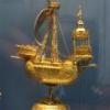
Boccherini Posted February 18, 2023 Author Share #141 Posted February 18, 2023 Thanks Wefalk. Compass: this was an interesting project, the most "complex" in my short hobby machinist career. I forgot to take pictures of the compass base process. The compass base and top were from 8mm brass rod cut down to 6.5mm to allow for the bottom flange, then down to 5mm for the two parts of the compass. The wings were folded from .25mm brass sheet. The base was drilled out to reduce the possibility of melting the "wings" during brazing. I had to use solder wire, paste dried out before it melted while trying to heat the parts without melting the "wings". The wire required use of flux paste, this also prevented the solder from smearing all over the place, wrecking the finish. Epoxy resin was used to assemble the finished item. A pin was epoxied into the base to locate it on the skylight. The finished item is 7mm high. I'll possibly paint the 2 compensating spheres, 1 red, the other green. Grant. Tony Hunt, Ainars, Rudolf and 7 others 7 3 Quote Link to comment Share on other sites More sharing options...
Jim Lad Posted February 18, 2023 Share #142 Posted February 18, 2023 Yes, remember the quadrantal correctors are soft iron, so they'll need painting, Grant. Red and green was a traditional colour scheme for them right up into the late 20th century! John Glen McGuire and mtaylor 2 Quote Link to comment Share on other sites More sharing options...
Boccherini Posted February 19, 2023 Author Share #143 Posted February 19, 2023 Thanks for the information John. Why "quadrantal" correctors? I was under the impression they were used to compensate for the effect of iron/steel used in a ship's construction. Regards, Grant. Glen McGuire and mtaylor 2 Quote Link to comment Share on other sites More sharing options...
wefalck Posted February 19, 2023 Share #144 Posted February 19, 2023 Nice work on the binnacle/compass! These 'Kelvin-balls' are there to correct the 'deviation' (horizontal deflection) of a compass caused by iron elements used in the construction or of iron articles in the load. Ther is also a vertical deflection called 'inclination' that is compensated for in later magnetic compasses. On road-steads there was usually an area set aside so that ships could steer a full 360° circle while making compass readings and observations of two given landmarks at the same time. This allowed to plot the 'deviation' of the compass readings from the theoretical readings. This plot was used to adjust the 'balls' in order to minimise the deviation. In the absence of such adjusting features, the 'deviation table' could also be used during a voyage to correct the course. I am not sure though, whether a wooden sailing ship, such as HARRIET McGREGOR would have had at that time this kind of correction features. There were older correction features, but they are not as prominent. Glen McGuire and mtaylor 2 Quote wefalck panta rhei - Everything is in flux Link to comment Share on other sites More sharing options...
Boccherini Posted February 19, 2023 Author Share #145 Posted February 19, 2023 Wefalk, I appreciate the lesson, thanks. I've included the balls because they are shown on the plan. I have discovered some discrepancies between the plans and pictures that are still available. Which leaves me in a quandary, correct things or not. At present, I'm leaning toward not bothering. There are so many other mistakes, it's probably not worth the effort. The model is becoming a very lengthy teaching moment. In spite of the mistakes, I'm committed to completing her. Much still to be learned in the process. Regards, Grant. Glen McGuire and mtaylor 2 Quote Link to comment Share on other sites More sharing options...
wefalck Posted February 19, 2023 Share #146 Posted February 19, 2023 Grant, it wasn't meant to be a 'lesson', just some observations. If sources tell you that the binnacle had (at some stage) Kelvin balls, that's it then. Ships change over time, so it is extremely difficult to represent a particular ship 'correctly'. Your sources from different times may show you certain features, but unless you have corroborating sources, you cannot know whether at another time the same features were present. So you may indadverntely create anachronisms simply because you don't know any better. That's the fate of any modeller. Contextual historical information, say the date of the Kelvin patent, can help you bracketting the time, when certain features could be present on a particular ship. Glen McGuire and mtaylor 2 Quote wefalck panta rhei - Everything is in flux Link to comment Share on other sites More sharing options...
Boccherini Posted February 20, 2023 Author Share #147 Posted February 20, 2023 (edited) Lessons, observations, comments (call them what you will, I'm not fussed).....I appreciate that you take the time to share your knowledge. I checked Kelvin's patent: 1876. Harriet McGregor (the ship, not Mr. McGregor's wife): 1871 - 1895. Thanks again, Grant. Edited February 20, 2023 by Boccherini Glen McGuire, wefalck and mtaylor 3 Quote Link to comment Share on other sites More sharing options...
Roger Pellett Posted February 20, 2023 Share #148 Posted February 20, 2023 (edited) In the US Navy these are sometimes called “The Admiral’s Balls.” Deviation is compass error, caused by ferrous metals aboard ship. Variation is compass error caused by geographic location. Navigators must consider both. Nautical charts usually show variation. The compass can be remarkably sensitive to the influence of ferrous metals. I have read accounts where a steel wrench left near a vessel’s pilot house has caused a grounding or worse. Even though this is a wooden vessel there was still a significant quantity of iron aboard; anchors, chain cables, and other fittings. And, once the vessel was placed in service, her designers had no control over the cargos that she might carry. Also, these binnacles were usually standardized items bought from ship chandlers so the Kelvin-Balls would have been included. For these reasons, I believe that including them on your model is correct. Just paint them. Making mistakes and deciding which to correct as they say “goes with the territory” when building ship models. In your case you are building a beautiful model of which you can be proud. Roger Edited February 20, 2023 by Roger Pellett mtaylor and Keith Black 2 Quote Link to comment Share on other sites More sharing options...
Boccherini Posted February 21, 2023 Author Share #149 Posted February 21, 2023 Thanks Roger. mtaylor and Roger Pellett 2 Quote Link to comment Share on other sites More sharing options...
Keith Black Posted February 28, 2023 Share #150 Posted February 28, 2023 Lord Kelvin patented his compensating spheres in the 1880's, the Harriet McGregor was destroyed by fire in 1895. Your binnacle is just fine and beautifully done, Grant. In fact, your entire build is beautifully done. It's a pleasure viewing your build log. mtaylor and Tony Hunt 2 Quote Current Builds: Wood Hull Screw Frigate USS Tennessee Decorative Carrack Warship Restoration, the Amelia Completed: Early Swift 1805 Model Restoration Link to comment Share on other sites More sharing options...

Recommended Posts
Join the conversation
You can post now and register later. If you have an account, sign in now to post with your account.