Walter Biles Posted February 21, 2013 Share #1 Posted February 21, 2013 (edited) I am interested in HOW do the chain pumps lift the water. The mechanism puzzles me. I understand the auger, and the rod lift into a back checked line, but what did they use to cause a lift to the water to get it up to a discharge point, and did they have an overboard discharge someplace to keep the water off the deck while in action? Walt Biles Edited February 21, 2013 by Walter Biles Quote Current: America Schooner https://modelshipworld.com/index.php?/topic/10887-america-schooner-pof-by-walter-biles-radio-pof-scale-148-from-blue-jacket-plan/ Prior: MERIDEA https://modelshipworld.com/index.php?/topic/140-meridea-by-walter-biles-radio-34-scratch-cad-of-boat-at-usn-severn-river-repair-station-ca-1969/ SAMSON First build: Scratch POF Spanish Galleon Link to comment Share on other sites More sharing options...
trippwj Posted February 21, 2013 Share #2 Posted February 21, 2013 (edited) Fairly simple principle in theory, more complicated to build correctly in the innards of a ship. The chain pump is type of a water pump in which several circular discs are positioned on an endless chain. One part of the chain dips in to the water, and the chain runs through a tube, slightly bigger than the diameter of the discs. As the chain is drawn up the tube, water becomes trapped between the discs and is lifted to and discharged at the top. The discharge varied by vessel - some discharged directly to the deck and then the water would run off through the scuppers. Others there was a pipe from the top to the scupper to contain the flow - particularly when the discharge was not on the spar deck. There is a really good description of the different types of pumps used in Historic Ship Models by Wolfram Zu Mondfeld. I found a preview on Google books - definitely need to get this book for my collection! Edited February 21, 2013 by trippwj Walter Biles and WackoWolf 2 Quote WayneNeither should a ship rely on one small anchor, nor should life rest on a single hope.Epictetus Link to comment Share on other sites More sharing options...
Walter Biles Posted February 21, 2013 Author Share #3 Posted February 21, 2013 (edited) Thank you Wayne, That answers part of the question. Didn't they have to have some sort of guidance at the lower end so that the little buckets didn't get hung up going into the bottom? Also, how did they keep the bucket and the chain on the sprockets at the top from skipping when the dipper went over the driver wheel? I wonder about these things. It seems like it would have to affect how someone could model this. Walt Biles Edited February 21, 2013 by Walter Biles Quote Current: America Schooner https://modelshipworld.com/index.php?/topic/10887-america-schooner-pof-by-walter-biles-radio-pof-scale-148-from-blue-jacket-plan/ Prior: MERIDEA https://modelshipworld.com/index.php?/topic/140-meridea-by-walter-biles-radio-34-scratch-cad-of-boat-at-usn-severn-river-repair-station-ca-1969/ SAMSON First build: Scratch POF Spanish Galleon Link to comment Share on other sites More sharing options...
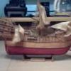
trippwj Posted February 21, 2013 Share #4 Posted February 21, 2013 Based on what I saw in Zu Mondfeld, they were actually leather disks. The pipe (tube) was almost a "U" shape but there was an opening in the bend at the bottom with openings in the tubes where the disks would pick up the water - apparently they never were out of the tubes. The return (down) tube was larger in diameter (reduced friction would be my guess) than the up (lift) tube (needed to be a tight fit to move the water up). Supposedly, a good pump and crew could move about a ton of water per minute from the ship. Here is a snapshot of the diagram from Zu Mondfeld. Walter Biles, WackoWolf and fnkershner 3 Quote WayneNeither should a ship rely on one small anchor, nor should life rest on a single hope.Epictetus Link to comment Share on other sites More sharing options...
Walter Biles Posted February 21, 2013 Author Share #5 Posted February 21, 2013 Thank you Wayne, I like that drawing. It was more understandable. A ton of water/min. How big was the diameter of the lift pipe? I have been trying to figure the approximate gpm that would be. They must have had to have had more than one pump on big ships. On only a 200 ton vessel that would amount to 200 minutes of pumping. They definitely would have to have had plenty of men to swap out as they got worn out. If they got a very big leak in the hull, such as a board rotted out for a foot, it would keep them going. (I had been considering that from the Update to the Bounty sinking.) I know they would have had to have current day pumps for that by legal standards, but after the level got up to them, they wouldn't have them. I'm wondering if they had the older pumps to fall back on or were they were ornamental. Walt Biles Quote Current: America Schooner https://modelshipworld.com/index.php?/topic/10887-america-schooner-pof-by-walter-biles-radio-pof-scale-148-from-blue-jacket-plan/ Prior: MERIDEA https://modelshipworld.com/index.php?/topic/140-meridea-by-walter-biles-radio-34-scratch-cad-of-boat-at-usn-severn-river-repair-station-ca-1969/ SAMSON First build: Scratch POF Spanish Galleon Link to comment Share on other sites More sharing options...
Walter Biles Posted February 21, 2013 Author Share #6 Posted February 21, 2013 (edited) In the navy, our portable pumps were either 250 gpm or 500 gpm. It took us hours to pump all the deck level downward on an 75' boat. and we could only get those 2 into the area. However we did not have any water coming in by then. It was lifted out by a huge floating crane. I know the check valve that failed was on a 10" discharge, and the boat sank in less than an hour. By my recollection a 10" pipe will handle about 800-1000gpm. Man that rot in their hull must have been something. Walt Biles Edited February 21, 2013 by Walter Biles Quote Current: America Schooner https://modelshipworld.com/index.php?/topic/10887-america-schooner-pof-by-walter-biles-radio-pof-scale-148-from-blue-jacket-plan/ Prior: MERIDEA https://modelshipworld.com/index.php?/topic/140-meridea-by-walter-biles-radio-34-scratch-cad-of-boat-at-usn-severn-river-repair-station-ca-1969/ SAMSON First build: Scratch POF Spanish Galleon Link to comment Share on other sites More sharing options...
dafi Posted February 21, 2013 Share #7 Posted February 21, 2013 Hy Walt, here is something about the chain pumps incl. the dales of HMS Victory: #157 Regards, Daniel Quote To victory and beyond! http://modelshipworld.com/index.php?/topic/76-hms-victory-by-dafi-to-victory-and-beyond/ See also our german forum for Sailing Ship Modeling and History: http://www.segelschiffsmodellbau.com/ Finest etch parts for HMS Victory 1:100 (Heller Kit) and other useful bits. http://dafinismus.de/index_en.html Link to comment Share on other sites More sharing options...
smatsik Posted February 24, 2013 Share #8 Posted February 24, 2013 Walt, Your ton a minute figure corresponds to on the order of 250 gpm. I did not do the figure exact so I could easily be off 50 gpm, but that gives you an idea of the rough value. Hoss Walter Biles 1 Quote Link to comment Share on other sites More sharing options...
trippwj Posted February 24, 2013 Share #9 Posted February 24, 2013 On these chain pumps, the volume/mass removed per minute is more a factor of the capability to turn the crank at a high enough rate. Larger diameter pipe would mean more water in each deisk, more mass/weight to be lifted. At some point, a critical relationship between strength of materials, crank speed and crew strength gets crossed. I know in firefighting, we use 4 inch diameter hose from the hydrant to the pumper. At hydrant pressure we get between 750 and 1250 Gallons Per Minute delivered to the pump. Walter Biles 1 Quote WayneNeither should a ship rely on one small anchor, nor should life rest on a single hope.Epictetus Link to comment Share on other sites More sharing options...

Recommended Posts
Join the conversation
You can post now and register later. If you have an account, sign in now to post with your account.