Fam Posted February 20, 2015 Author Share #31 Posted February 20, 2015 February 20th, 2015 Hi all it’s been a long time since my last post, finally I’m back home from my business trip and the shipyard is re-opened! Have to admit that I missed it a lot, I was scratching my hands for the need to touch some wood and some tools!!! Am I ship-aholic enough? Obviously I restarted from what I had left uncompleted, i.e. the wales. The stbd wale was already installed, but still unfaired, the port wale was missing. So, as first I completed the job on the left hand side, repeating exactly what I’ve done on the right... not exactly at all, as I did two alignment mistakes at midship and at poop: height of the wale, measured from the top of the bulwark, did not came out same as on the right regardless of thousand measurements I did! Probably the first strake slipped a little bit when applied pressure to set it. Not a difficult task to fix it, just time consuming: I added two small slivers where required and then sanded all flush... done! After the 1st strake was correctly set, I had no more problems for the remaining two strakes. Then I had to merge the wales onto the standard planking of the hull, but only on the lower edge: I had to take care of the upper edge so that the step remained unaltered. And finally this is the result: you can see the different texture and color of the Cirmolo wood, and how the wale thickness is smoothly reduced to zero. At the bow I had no evidence of what Chuck found for his Cheerful cutter, i.e. that the wales’ thickness decreases to zero where they enter into the rabbet of the stem piece: the Ancre plans are not so clear in this detail, so I preferred to leave them at the complete thickness. This was another milestone reached for the project: now it is possible to step forward and start working on the deck! Well, before I completed the fairing of the transom, on the starboard side, but that was just a matter of 5 minutes... The first task in the deck area, before installing the false deck, was to reduce the thickness of the top-timbers. So, started the demolition days! 3 days, with sharp scalpels, files and sand paper. To help getting a uniform thickness I built a template, which can be seen in the second picture: a slot in a piece of scrap plywood that reproduced the combined thickness of the top-timbers and the external planking: 3mm on top, 3.5mm at the bottom. Every top timber was slowly cut, removing thin layers from the inside and continuously measuring with the template. This is the result, almost ready for internal planking! But before this can be done, lots of other jobs have to be completed. I tried to schedule the sequence of working, as my method will be quite different from JA’s. I will locate the openings of the gunports, and of the oar-ports as well, and then will create the surrounding frame simulating the real structure of each port linings. Then the internal planking will be installed, completing the bulwark: their thickness will remain empty, contrary to JA who preferred to build a solid wood bulwarks. So my sequence will be the following: false deck waterways define the gunports & oarports opening locations install the opening linings install the internal planking cut the openings First task so was to lay the false deck, which is a layer of thin plywood that will support the deck planking. I used thin cardboard to firstly create a shape template ... anybody knows better material than scrap corn-flakes boxes? I’ve got some 0.8mm thick plywood, 4 sheets of A4 format, but the deck is so big that I had to divide its length in three parts. Of course the deck will also be cut along the hull center-line, so this makes 6 pieces in total. For this reason, I have 2 joints along the deck and I need a good supporting surface for the fore and aft ends of the false-deck pieces. As the bulkheads are only 5mm thick, I enlarged a little bit the supporting structure by gluing two pieces of 5mm plywood to the front side of bulkheads nn. M2 and VI Next step ... gluing the false-deck pieces! Stay tuned Fam druxey, Mfelinger, tarbrush and 12 others 15 Quote Joint building: Brick de 24, 1/48, jointly with Jack Aubrey (POB from Ancre plans) Works in progress: USS Constitution Cross Section, 1:93 (POF bashed from Mamoli kit) Completed models: Santìsima Trinidad, 1/90 (POB heavily modified DeAgostini kit) Genoan Pinco, 1/50 (POB bashed from Euromodel plans - my current avatar) Viking Knarr, 1/72 (POF from Dusek kit) Link to comment Share on other sites More sharing options...
Fam Posted March 2, 2015 Author Share #32 Posted March 2, 2015 (edited) March 02nd, 2015 Hi all new small update from my 'Brick de 24' shipyard... I’ve completed the laying of the false deck, built with 0.8mm plywood. Each of the 6 pieces needs to be fixed on the perimeter and along the bulkheads, so before starting I had to perfectly prepare the supporting surfaces so that all the pieces are joined without discontinuities, as if they were a single piece... considering the double curvature of the deck it was not that easy!! Of course I had to cut the holes for the masts before covering their position. This is the completed job, after a final sanding and after having marked the positions of the bulkheads... The lines of the bulkheads are needed for aligning the butt joints of the deck planks, even considering that the bulkheads top-timbers are going to disappear, either removed or hidden behind the internal planking. Next step, as scheduled, was the waterways... Damn, a real dusty affair this! I used limewood cut in blocks, 5 pieces per side. The problem is that there are no two surfaces square to each other, each piece took really a long time and a lot of sawdust!! How to proceed? I developed a method which is mine, maybe not the best nor the quickest... but worked! Don’t know if it works for everybody (Ed Tosti with his tenth of waterways of all possible shapes is the person I mostly admire, he makes it look so easy...) I started from the bow, because these are the most difficult pieces to build due to the curvature, the variable slopes of the bulwarks and the thickness variation. You can see a darker piece of pearwood at the bow, along the centreline: it is a piece of the bow timber protruding inside the bulwarks, so I set it as first as the starting point. It is cut from the same type of timber as the stem pieces. - First: the curvature matching the top-timbers is cut from the limewood piece, using the cardboard templates of the false-deck to define the rough shape - Second, the top-timbers are not square to the deck surface: e.g. for the above shown bow pieces they are sloped outboard close to the bow timber (about 5deg) and then become sloped inboard (about 8deg) from bulkhead #VI, with a smooth transition between the two positions. I used the new disk sander (a perfect tool for this job, indeed!), adjusting the tilting table and very lightly touching the piece of wood with the sanding disk, one mm at a time, with continuous fit tests against the top timbers - Third: after the piece matches the bulwark, I had it to match the deck longitudinal curvature. In the above picture it is apparent that the central part of the 2nd piece is raised in the middle from the false-deck, due to the curvature of the latter. So another 'kissing' of the sanding disk is needed. - Fourth: cross (athwartship) thickness. Luckily, it is constant so I used a compass to trace, on the lower surface of the piece, a line parallel to the external edge. Then I cut with a scroll saw along this line and sanded it smooth. - Fifth: vertical thickness. The two bow pieces have linearly variable thickness, so I had to draw a ‘straight’ line using a guiding flexible ruler from one end of the piece to the other. Then again I cut with a scroll saw along this line and sanded it smooth with the sanding disk. Again luckily, the other pieces have a constant height, so they are much more easily traced and cut. Sometimes, to avoid erroneous cuts, I used a sharp cutter instead of the scroll saw, removing small slivers at a time and finally sanding with a sanding block - Sixth: the internal slope, the easiest part of the job! I traced with the compass two lines, one on the top face 1.5mm inboard of the external edge, and the other on the internal vertical face 1.5mm above the deck (they can be barely seen in the above picture, on the last-but-one piece). Then joined the two lines by removing the excess material with a cutter. That’s all: I had to repeat the same sequence for the 10 pieces, plus the two curved pieces at the bow that I had to rebuild twice! In total it took four working evenings (about 8 hours), and this is the result, finally completed: I’m not going to glue these pieces now: I’ll keep them floating on the deck, just temporarily fixed in position to act as spacers for setting the bulwarks internal planking. The planking is cut from the same boxwood as for the bulwark exterior, that is quite hard to sand smoothly and needs a power tool to get a fine finish... so I don’t want to risk ruining all this job while sanding the planking!! Next job: before going forward, I decided to define the positions of the 4 hawse holes so to ease the job of refining them after the hull exterior is finished with the 2nd planking... and before definitely fixing the waterways, just in case... The hardest was to identify the holes position inboard and putboard, as they are sloping downward but very few references are available. The pilot holes were drilled by hand... the first attempt at starboard was not so good ... the second shot at port much better! And seen from outside... After correcting the alignment of the stbd hawse holes ... the next scheduled step was to define the position of all the openings in the bulwarks. This is the final result of lot of measurements (sorry, the picture is a bit dark). Now I'm ready to start drilling and cutting! The first will be the oar holes... Ciao Fam Edited March 3, 2015 by Fam archjofo, mtaylor, hexnut and 9 others 12 Quote Joint building: Brick de 24, 1/48, jointly with Jack Aubrey (POB from Ancre plans) Works in progress: USS Constitution Cross Section, 1:93 (POF bashed from Mamoli kit) Completed models: Santìsima Trinidad, 1/90 (POB heavily modified DeAgostini kit) Genoan Pinco, 1/50 (POB bashed from Euromodel plans - my current avatar) Viking Knarr, 1/72 (POF from Dusek kit) Link to comment Share on other sites More sharing options...
cog Posted March 2, 2015 Share #33 Posted March 2, 2015 Fam, Great explanation, thanks. Even a slow advance is some progress. Looking good. Fam 1 Quote Carl "Desperate affairs require desperate measures." Lord Nelson Search and you might find a log ... Link to comment Share on other sites More sharing options...
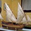
Fam Posted March 3, 2015 Author Share #34 Posted March 3, 2015 (edited) Thank you for the kind words, Carl, I have to admit that I'm proceeding slower than I would like but cannot do anything more than stealing any free minute I have from my family life... if I don't have enough time to sit down and concentrate on what I have to do, I prefer not starting working at all ! Better not rushing in this hobby, this is my philosophy Just speaking of short time, yesterday evening managed to drill the holes for the oar ports, 7 on each side. Then stopped again to think a little bit about the orientation of the slot permitting the oar blade to be slipped through... which side? Toward the bow or toward the poop? this is the same picture that JA showed in his build-log, from the monography. I've also found this picture of the Le Cyclope, showing both opened and closed oar ports: I thought that when pushing on the oar handles for rowing, the oar pushes back (as a reaction) against the forward border of the oar port. So, coherently, the slot should be oriented toward poop, to reduce the wearing of the hole walls. If this is true, the ports in Le Cyclope are wrongly oriented... any suggestion? In the first picture above I also simulated the rotation of the port lids (blue line), to verify that its shape and size are adequate to close the oar ports... and they are ! Regards Fam Edited March 3, 2015 by Fam IgorSky, antanasp, kees de mol and 3 others 6 Quote Joint building: Brick de 24, 1/48, jointly with Jack Aubrey (POB from Ancre plans) Works in progress: USS Constitution Cross Section, 1:93 (POF bashed from Mamoli kit) Completed models: Santìsima Trinidad, 1/90 (POB heavily modified DeAgostini kit) Genoan Pinco, 1/50 (POB bashed from Euromodel plans - my current avatar) Viking Knarr, 1/72 (POF from Dusek kit) Link to comment Share on other sites More sharing options...
cog Posted March 3, 2015 Share #35 Posted March 3, 2015 Fam, The picture of Le Cyclope does not give me a clear indication as I do not know which way is bow or stern. Your reasoning, however, is sound. On the other hand, since the oars - pulled or pushed - is to thick (but for the blade) to pass through the upper narrow part of the teardrop, thus, it doesn't matter much which way it will point. This as far as my two cents go ... Quote Carl "Desperate affairs require desperate measures." Lord Nelson Search and you might find a log ... Link to comment Share on other sites More sharing options...
Fam Posted March 3, 2015 Author Share #36 Posted March 3, 2015 Bow to the right, see pinnace orientation and shrouds slopes ... Fam Quote Joint building: Brick de 24, 1/48, jointly with Jack Aubrey (POB from Ancre plans) Works in progress: USS Constitution Cross Section, 1:93 (POF bashed from Mamoli kit) Completed models: Santìsima Trinidad, 1/90 (POB heavily modified DeAgostini kit) Genoan Pinco, 1/50 (POB bashed from Euromodel plans - my current avatar) Viking Knarr, 1/72 (POF from Dusek kit) Link to comment Share on other sites More sharing options...
druxey Posted March 3, 2015 Share #37 Posted March 3, 2015 One usually pulls on an oar as one faces toward the stern. It seems to me that the illustration is correct, but not the model. mtaylor and Fam 2 Quote Be sure to sign up for an epic Nelson/Trafalgar project if you would like to see it made into a TV series http://trafalgar.tv Link to comment Share on other sites More sharing options...
cog Posted March 3, 2015 Share #38 Posted March 3, 2015 (edited) Ah Druxey, But zey are Frensh The French did things different from the English, so that would not be so strange... Furthermore, they would be standing and not sitting ... might be easier to push, at least you would be stronger pushing. Edited March 3, 2015 by cog mtaylor and Fam 2 Quote Carl "Desperate affairs require desperate measures." Lord Nelson Search and you might find a log ... Link to comment Share on other sites More sharing options...
Fam Posted March 3, 2015 Author Share #39 Posted March 3, 2015 (edited) Well, to me regardless if the man is pushing or pulling the handle of the oar, seating or standing, the fulcrum of the lever (oar) is pushing agaist the hull in the direction of ship/boat motion.... that makes the ship/boat move... Then agree with Carl that on a ship of the size of a Brig it's probably easier to stand facing forward and pushing forward on the oar handle (similar to the way rowing is done on a Venice Gondola), while on a small boat its easier rowing while seated, facing the stern, pulling the handle. So I think that if the shape of the hole in the bulwark is regular in the forward side (i.e. no slot), as forward is supposed to be the most used direction of hull motion under rowing, the strenght of the wooden parts subject to friction should be greater... or not? I've searched in the monography for other information but have not found anything more than that little sketch Thank you again, I really appreciate your help and, if no other idea or illuminating picture pops up, I'd proceed by cutting the slots backward and upward Fam Edited March 3, 2015 by Fam mtaylor 1 Quote Joint building: Brick de 24, 1/48, jointly with Jack Aubrey (POB from Ancre plans) Works in progress: USS Constitution Cross Section, 1:93 (POF bashed from Mamoli kit) Completed models: Santìsima Trinidad, 1/90 (POB heavily modified DeAgostini kit) Genoan Pinco, 1/50 (POB bashed from Euromodel plans - my current avatar) Viking Knarr, 1/72 (POF from Dusek kit) Link to comment Share on other sites More sharing options...
cog Posted March 3, 2015 Share #40 Posted March 3, 2015 (edited) I would go for the oposite side, forward, because pushing or pulling it won't bother the rowing motion, whilst rearwards, it may hinder the start of the stroke ... Edited March 3, 2015 by cog mtaylor 1 Quote Carl "Desperate affairs require desperate measures." Lord Nelson Search and you might find a log ... Link to comment Share on other sites More sharing options...
Fam Posted March 3, 2015 Author Share #41 Posted March 3, 2015 (edited) Thank you, I'll consider your point and think a bit more about it I add another picture for helping the discussion: the Oseberg Drakkar (slots oriented backward) Regards Fam Edited March 3, 2015 by Fam mtaylor and cog 2 Quote Joint building: Brick de 24, 1/48, jointly with Jack Aubrey (POB from Ancre plans) Works in progress: USS Constitution Cross Section, 1:93 (POF bashed from Mamoli kit) Completed models: Santìsima Trinidad, 1/90 (POB heavily modified DeAgostini kit) Genoan Pinco, 1/50 (POB bashed from Euromodel plans - my current avatar) Viking Knarr, 1/72 (POF from Dusek kit) Link to comment Share on other sites More sharing options...
Fam Posted March 5, 2015 Author Share #42 Posted March 5, 2015 Hi all just a check on the correct wording I should use in English, if anybody can confirm... - camber = curvature of the deck athwarthship, i.e. in the port-starboard direction - sheer = curvature of the deck longitudinally, i.e. in the stem-stern direction thank you in advance Fam Quote Joint building: Brick de 24, 1/48, jointly with Jack Aubrey (POB from Ancre plans) Works in progress: USS Constitution Cross Section, 1:93 (POF bashed from Mamoli kit) Completed models: Santìsima Trinidad, 1/90 (POB heavily modified DeAgostini kit) Genoan Pinco, 1/50 (POB bashed from Euromodel plans - my current avatar) Viking Knarr, 1/72 (POF from Dusek kit) Link to comment Share on other sites More sharing options...
Fam Posted March 13, 2015 Author Share #43 Posted March 13, 2015 (edited) March 13th, 2015 Hi all another small update from my “Brick de 24” shipyard... I’ve been working all these days (slow paced, I admit) on the inside of the bulwarks to prepare the gunports and oarports framing. First step, after locating the position of the oarports, was to drill and cut them. My conclusion from the above discussion was that the slot for slipping through the oar blade must be positioned backward and upward, so this was the result from outside: Note how the oarports are aligned to the plank strakes... this was the leit-motiv for all the alignment checks, greatly helping this difficult task also for the framing. Next was the preparation of the oarports framing: I decided to work on the bench, because it’s easier, quicker and less time consuming. So cut several strips of pearwood, the same lighter quality I’ve already used for the transom gunports lining. They are 2mm thick and wide enough to match the maximum thickness of the top-timbers at the bulwark base. I cut much more strips then I needed for the oarports, as they are the same also for the gunports framing. Then cut a couple of these strips into 5.5mm pieces, which is the width size of the rectangular ports (see above drawing). Material preparation took no more than 5 minutes, the table saw is great for this job! I then sacrificed 3 of these pieces for preparing a very simple jig: they just serve as spacers for the two long battens, fixing their correct distance. Then marked on both battens a series of 4.5mm long segments parallell to each other, and simply glued the remaining pieces between the battens using the markings for their alignment. The result is visible below for two ports, but I managed to prepare 7 framings at a time in this way! Each framing is well spaced from the next, because my intention was to use the long legs as a replacement of the top-timbers that I was going to remove. Here it is how: Almost the same procedure was used for the gunport framing, but this time I worked directly on the model because the framing structure is not boxy-like, so needs a more attentive positioning to respect the required alignments. Firstly I had to transfer to the planking inside the gunports markings, then (with the positions of the battens defined) I cleaned the internal surface of the planking from any residual of glue and prepared for a good matching with the battens. I cut them slightly longer than needed, to let for some fine adjustment, and then glued them in position... JA had warned me that I was going to encounter some difficulty, because of the many top-timbers interfering with the framing positioning... well it was partly true but only slowed down my job because I had to proceed per steps: - firstly I glued the battens in the free positions, and let them dry - then, with the installed battens strengthening and supporting the bulwark, I cut the interfering top-timbers - most of them were only narrowed, leaving as much material as possible to avoid weakening excessively the bulwark: it was a time consuming and delicate job, with small shavings at a time, then cleaning, then shaving, then cleaning... - a couple of top-timbers had to be completely removed - when all the vertical battens had been glued, I started with the horizontal gunport sills: measurement was important in this case, because they must be parallel to the deck and to the gunwale (top edge of bulwark) and exactly at 16.5mm from the gunwale. - again, in most cases I had to remove portions of top-timbers where they are located exactly in the middle of a gunport. The following are shots of the works in progress and of the final result (starboard side). As you can see I had to proceed in parallel port and starboard, in order to wait for the glue to set. After this job was completed, I had to reduce the thickness of all the framing pieces to match the correct thickness of the bulwark structure: 3.5mm at the base, 2.5mm at the top, another very long job to be done, because the correct alignment of all these battens is affecting the flow of internal planks! Once again, JA method was much easier and quicker but I’m not sure if my good friend managed to get the variable bulwark thickness with his method... I will ask him Finally, this is a shot of yesterday evening work: the first internal plank is glued! This plank is the most difficult of the first (lower) strake, because its lower edge has to match the rising waterway while the upper edge has to remain parallel and 16.5mm down from the top of the bulwark... this also means that this strake is wider than the other, because the combined height of the waterway and 1st strake needs to match the total height of two strakes on the outside. I had to use one 8mm thick boxwood piece (the maximun I own), and sliced it into 1.25mm thick planks... luckily I had just bought a new “Super-cut” blade for the table saw, because the older one was too worn to go through this hard wood! Having the table-saw set, I also cut all the planks for the bulwark inside: 5mm wide (to be reduced), 1.25mm thick. The shape of the above plank was defined by slipping a piece of thick paper between the waterway and the bulwark framing (another reason for not fixing the waterway! ), then the pencil was run along the waterway upper border (thus marking the lower plank edge shape) and along the top of bulwark external planks. The latter marking gave me the reference, when lowered by 16.5mm, for the upper edge of the plank. This template was then transferred to one 8mm wide plank and cut. Then curved (as usually, by water and heat), measured, fine trimmed below and above, until I was totally satisfied. Note how the upper edged of the plank matches the sills of the first two gunports! And finally... it was glued in position! 2 hours to get this result... The forward waterway piece was left in position for a while, just to be sure that the plank was correctly positioned, and then removed to avoid it to remain glued by any excess of glue from the above plank, which I want absolutely to avoid! The next job should be slightly easier, as the remaining planks of the 1st strake are constant width... just a matter of matching the distance between the top of waterway pieces and the gunport sills. Stay tuned Best regards Fam Edited March 30, 2015 by Fam druxey, kees de mol, hexnut and 2 others 5 Quote Joint building: Brick de 24, 1/48, jointly with Jack Aubrey (POB from Ancre plans) Works in progress: USS Constitution Cross Section, 1:93 (POF bashed from Mamoli kit) Completed models: Santìsima Trinidad, 1/90 (POB heavily modified DeAgostini kit) Genoan Pinco, 1/50 (POB bashed from Euromodel plans - my current avatar) Viking Knarr, 1/72 (POF from Dusek kit) Link to comment Share on other sites More sharing options...
Fam Posted March 30, 2015 Author Share #44 Posted March 30, 2015 March 30th, 2015 Hi all, here I am with another update from my shipyard! During these 2 weeks I managed to complete 4 tasks on the deck structures: - completion of the bulwarks internal planking - completion of the waterways, with the addition of those at the transom - planking of the transom - preparation and fitting of the 6 sheave blocks in the bulwarks The first internal plank at the bottom of the bulwark is a wider one and needs some adaptation to match the curvature of the waterways. The technique I used is described in the previous post, so no need to repeat. The next picture shows two planks with their paper templates... ... this shows the first strake completed, with a bent plank for the second strake ... ... and this shows the last strake of the starboard bulwark fixed and glued... The transom required a special attention due to its double-curvature: I had firstly to prepare the waterways for this area... the plans are not very clear about this, they show what appears to be a smooth transition from the deck planking to the counter planking more than a sloping waterway as for the bulwarks. So I prepared a sort of margin plank, only creating a small step to house the deck planks on one side and the counter planks on the other side. The counter planks are curved and tapered and are interrupted in the middle for the rudder hole. The starboard transom margin-plank is done (just left to cut to final length) and the port one is being shaped... Note that the transom gunports are shut: I had to add a thin layer of pear to get the correct thickness of the gunport lining. I re-opened the gunport just after planking the transom. So, here are the bulwarks, counter and transom completed with their internal planking. The waterways are still temporarily positioned, not glued yet. The bulwark planking is 1mm thick boxwood, while transom-counter planking is just 0.7mm thick. The bulwarks are not completed without their multiple-sheaves blocks. There are 6 of them: two with 6 horizontal sheaves each at poop, two with 5 horizontal sheaves each at the waist and two with 1 vertical sheave in the forecastle area. The multiple blocks are as wide as the bulwarks, so tapering upward from 5 to about 4.5mm. They are 5.5mm high and about 15.5mm large to house two series of 3 sheaves. The slots for the sheaves are about 1mm high, as can be measured on the plan, so I had to build a block 5.5mm high with 3x1mm slots, and the remaining thickness is left for the 4 spacers... just 0.6mm each! I think I reached the limit of my KS230 table saw, or very close, as I managed to slice 0.6mm layers from my 8mm thick boxwood with almost no imperfections... I’m a big fan of the Proxxon machines, even if this table-saw is a bit underpowered it always gives me great satisfaction! Next I prepared the spacers, 1x1mm, and also a 6.5mm square batten for aligning the spacers while gluing. Here are the steps: One slot in two of the above blocks is than blanked with a scrap piece of boxwood, so to create the 5 sheaves waist blocks. Preparation of the vertical single blocks was similarly accomplished, just with different measures. All the blocks were left wider than the thickness of the bulwarks, to permit a following better and easier finishing. The following task was to locate the blocks’ positions and to create their housings: easy-peasy for the forward-most 4 blocks, but it was a nightmare for the 2 rearmost blocks which are upward sloping and almost in contact with the transom. I had to partially dismantle the bulwarks where they join the transom in order to create the housings, then rebuilt them after having positioned, fitted and glued the blocks. Here is the result: After all the blocks were glued, I only had to sand them flush with the internal and external surfaces of the bulwark, and the job was completed with a good pass of abrasive paper for a smooth finish. The sheaves will be added later: they are 1mm thick (or slightly less) and 5mm in diameter... I'm thinking of using styrene plasticard ... will see how it works! The fourth and fifth pictures above also show the completed oarports, from inside and outside: their pearwood lining is also partially visible. The gunports are similarly prepared, but will be cut only after applying the second planking or, depending on how I will schedule the works, before fitting the gunwale. Finally, yesterday I’ve spent 3 hours cutting the deck planks with the table saw. The deck has a central area of thicker planks, 3mm, where all the deck fittings are installed (companionway, pumps, capstan, bitts, binnacle, boat supports and so on) and two side areas where the planks are thinner at 2mm. These thicknesses are referred to the top of the deck beams, so must be diminished by the thickness of the plywood false deck (i.e. 0.8mm). The central area has planks of different width, not too much but very evident. The central plank, along the ship center-line, is 5mm wide; then there are two planks each side of it, of 6mm width; finally another plank per side of 5.5mm width (total 7 strakes). These measures are taken at bulkhead 0, or M1/M2 in the model, where the planks have their maximum width. Then they are tapered toward bow and poop (with the exclusion of the central one) and slightly curved inboard. JA has found a brilliant way to set a guide for planking the deck with all the above variations, that is gluing to the false-deck several paper strips directly taken from (a copy of) the deck plan: this gives a continuous reference for the planks width to be used, as well as for tapering, greatly helping in preventing any error or inattention... thank you very much JA!! So, here below is the deck prepared with the paper guides: After this, I glued all the waterways pieces and smoothed their joints with some wood filler: these will be painted black later. Finally I started laying the center-plank from stem to stern: lot of care is required to lay correctly this first strake, as it will be the guide for the remaining deck planks. About the wood: it is Ramin for all the deck planks with the exclusion of the two “king” strakes, those by 5.5mm width at the boundaries of the central thicker band, which will be light pearwood. In the last picture the first plank of the second strake is being glued. To build this plank I measured its width at the stations were the paper guidelines are set (bulkheads nn.VIII, VI, IV and II), and pasted these measurements to the plank; next I tapered the plank with the disk sander. This plank will not be bent, because the center strake is not tapered nor curved, but with the following strakes I will have to add a slight bend after the tapering... hope it works, or I will need to take advantage of the full original plank width (10mm) to cut-out the correct shape including bending and tapering (that's to say spiling it!): this is why I only cut the amount of planks sufficient for the central thicker area, just in case they do not fit! Last details: - the planks are cut to 200mm length, equivalent to a bit less than 10 real meters. - I used a plank shift equivalent to two bulkheads - the butt joint of the planks with the waterway is apparently flat in the plans, but only the central portion of deck planking is shown. So I’m planning to use joggled planks starting from when the planks need to be mitered about 45° to match the waterways... same method as explained in the fantastic tutorial by Ed Tosti, a method that I’ve also used in my Pinco: To conclude, I have a consideration about deck planking: the deck fittings were fixed to the structures (beams) under the planking, so in theory they could be installed right now and then the planks cut to fit around them. I tried this approach with the Pinco, but then had lot of difficulties with the deck sanding, right because of the many obstacles in the way. So I’m now trying to add the fittings ‘on top of’ the planking, by cutting the required slots where needed for greater strength (for example for the bitts and pin-rails). That’s all for today... my best regards Fam archjofo, tarbrush, Mirabell61 and 6 others 9 Quote Joint building: Brick de 24, 1/48, jointly with Jack Aubrey (POB from Ancre plans) Works in progress: USS Constitution Cross Section, 1:93 (POF bashed from Mamoli kit) Completed models: Santìsima Trinidad, 1/90 (POB heavily modified DeAgostini kit) Genoan Pinco, 1/50 (POB bashed from Euromodel plans - my current avatar) Viking Knarr, 1/72 (POF from Dusek kit) Link to comment Share on other sites More sharing options...
Mirabell61 Posted March 30, 2015 Share #45 Posted March 30, 2015 Nice build Fam, deck, bulwarks look great, also those staggered sheet guides in the aft bulwarks Nils Fam 1 Quote Current builds -Lightship Elbe 1 Completed - Steamship Ergenstrasse ex Laker Corsicana 1918- scale 1:87 scratchbuild - "Zeesboot" heritage wooden fishing small craft around 1870, POB clinker scratch build scale 1:24 - Pilot Schooner # 5 ELBE ex Wanderbird, scale 1:50 scratchbuild - Mississippi Sterwheelsteamer built as christmapresent for grandson modified kit build - Chebec "Eagle of Algier" 1753--scale 1:48-POB-(scratchbuild) "SS Kaiser Wilhelm der Grosse" four stacker passenger liner of 1897, blue ribbond awarded, 1:144 (scratchbuild) "HMS Pegasus" , 16 gun sloop, Swan-Class 1776-1777 scale 1:64 from Amati plan -"Pamir" 4-mast barque, P-liner, 1:96 (scratchbuild) -"Gorch Fock 2" German Navy cadet training 3-mast barque, 1:95 (scratchbuild) "Heinrich Kayser" heritage Merchant Steamship, 1:96 (scratchbuild) original was my grandfathers ship -"Bohuslän" , heritage ,live Swedish museum passenger steamer (Billings kit), 1:50 "Lorbas", river tug, steam driven for RC, fictive design (scratchbuild), scale appr. 1:32 under restoration / restoration finished "Hjejlen" steam paddlewheeler, 1861, Billings Boats rare old kit, scale 1:50 Link to comment Share on other sites More sharing options...
cog Posted March 30, 2015 Share #46 Posted March 30, 2015 Great work Fam, like those sheave blocks, very neatly done Fam 1 Quote Carl "Desperate affairs require desperate measures." Lord Nelson Search and you might find a log ... Link to comment Share on other sites More sharing options...
Fam Posted March 31, 2015 Author Share #47 Posted March 31, 2015 (edited) Hi all many thanks for the likes! Yesterday evening I've completed the planking of the deck central band, 5 strakes of Ramin. Today I'd like to install the last two strakes of pear wood, the "king" strakes. I'm using a different wood to highligth the difference w.r.t. the standard planking, but not too much: so I'm using a light shade of pearwood which is quite similar to Ramin but I know it will come out a bit darker when applying any type of oil or finishing product. But I would like to remark better the difference of this strake, so I'd like also to use a different butt joint as opposed to the standard straight athwarthship type. As Ancre plans are not helping in any way on this topic, I'm asking opinions here... I think I have two possibilities: - scarf joints - hook joints These were used with different scopes, hook joint is (to me) a structural joint permitting to transmit stresses along the strake. So probably it better suits the scopes of the "king" strakes, that maybe is not merely decorative... Any opinion or idea? What was the standard contemporary practice? Thank you in advance for any suggestion Ciao Fam Edited March 31, 2015 by Fam Quote Joint building: Brick de 24, 1/48, jointly with Jack Aubrey (POB from Ancre plans) Works in progress: USS Constitution Cross Section, 1:93 (POF bashed from Mamoli kit) Completed models: Santìsima Trinidad, 1/90 (POB heavily modified DeAgostini kit) Genoan Pinco, 1/50 (POB bashed from Euromodel plans - my current avatar) Viking Knarr, 1/72 (POF from Dusek kit) Link to comment Share on other sites More sharing options...
cog Posted March 31, 2015 Share #48 Posted March 31, 2015 Fam, I am not familiar with a hook joint, any example? So to me, currently, I can only advise on scarf joint .. Quote Carl "Desperate affairs require desperate measures." Lord Nelson Search and you might find a log ... Link to comment Share on other sites More sharing options...
Fam Posted March 31, 2015 Author Share #49 Posted March 31, 2015 This is an example of what I mean... Thank you for your attention Fam mtaylor 1 Quote Joint building: Brick de 24, 1/48, jointly with Jack Aubrey (POB from Ancre plans) Works in progress: USS Constitution Cross Section, 1:93 (POF bashed from Mamoli kit) Completed models: Santìsima Trinidad, 1/90 (POB heavily modified DeAgostini kit) Genoan Pinco, 1/50 (POB bashed from Euromodel plans - my current avatar) Viking Knarr, 1/72 (POF from Dusek kit) Link to comment Share on other sites More sharing options...
cog Posted March 31, 2015 Share #50 Posted March 31, 2015 I would go for the last one if a lot of stress is expected in real life usage ... mtaylor and Fam 2 Quote Carl "Desperate affairs require desperate measures." Lord Nelson Search and you might find a log ... Link to comment Share on other sites More sharing options...
Fam Posted April 1, 2015 Author Share #51 Posted April 1, 2015 I did it! Managed to complete the port strake with 4 hook joints... very proud of myself!! Now hope to manage doing the same on the left, then will glue the two strakes and sand the entire central band before proceeding with the side bands. But this will be after Easter holidays, so Happy Easter to all MSW members! Fam antanasp, mtaylor and cog 3 Quote Joint building: Brick de 24, 1/48, jointly with Jack Aubrey (POB from Ancre plans) Works in progress: USS Constitution Cross Section, 1:93 (POF bashed from Mamoli kit) Completed models: Santìsima Trinidad, 1/90 (POB heavily modified DeAgostini kit) Genoan Pinco, 1/50 (POB bashed from Euromodel plans - my current avatar) Viking Knarr, 1/72 (POF from Dusek kit) Link to comment Share on other sites More sharing options...
cg451 Posted April 3, 2015 Share #52 Posted April 3, 2015 Fam, Wonderful work and excellent photography--thank you! One suggestion: even though the scarf joint is hooked and glued, I believe the practice was also to dowel virtually every joint. Since the dowels were made of wood, they became called "tree nails" which we in the US pronounce as "trunnels." In my furniture building I use dowels frequently (along with lots of mortise and tenon joints). As you know, nails of any sort are only there--theoretically--to hold the joint until the glue dries. However, in practice the dowels and trunnels do add strength. Others reading this: please chime in with additional comments. Bill Fam 1 Quote My library will never be complete, and my fleet will always be growing Link to comment Share on other sites More sharing options...
Fam Posted April 3, 2015 Author Share #53 Posted April 3, 2015 (edited) Thank you Bill actually I've already prepared a couple of samples of tree nails, to check how it comes out. I'm intentioned to tree-nail the entire deck and the visible (not painted) part of bulwarks. I'm going to use birch toothpicks. Bye Fam Edited April 3, 2015 by Fam Quote Joint building: Brick de 24, 1/48, jointly with Jack Aubrey (POB from Ancre plans) Works in progress: USS Constitution Cross Section, 1:93 (POF bashed from Mamoli kit) Completed models: Santìsima Trinidad, 1/90 (POB heavily modified DeAgostini kit) Genoan Pinco, 1/50 (POB bashed from Euromodel plans - my current avatar) Viking Knarr, 1/72 (POF from Dusek kit) Link to comment Share on other sites More sharing options...
Fam Posted April 7, 2015 Author Share #54 Posted April 7, 2015 (edited) Hi allfor the records, I've finally found (credits to 'daves') what is the type of wood I'm using for the bulwarks: Brazilian Satinwood, also known as Yellowheart, or Yellow Heart, Amarello or Pau Amarello...http://www.woodworkerssource.com/Satinwood_Brazil.htmlBotanical: Euxlophora paraensisBest regardsFam Edited April 8, 2015 by Fam antanasp and mtaylor 2 Quote Joint building: Brick de 24, 1/48, jointly with Jack Aubrey (POB from Ancre plans) Works in progress: USS Constitution Cross Section, 1:93 (POF bashed from Mamoli kit) Completed models: Santìsima Trinidad, 1/90 (POB heavily modified DeAgostini kit) Genoan Pinco, 1/50 (POB bashed from Euromodel plans - my current avatar) Viking Knarr, 1/72 (POF from Dusek kit) Link to comment Share on other sites More sharing options...
Fam Posted April 13, 2015 Author Share #55 Posted April 13, 2015 (edited) April 13th, 2015 Hi all I’ve some new pictures to show with a small update from my shipyard of “Le Brick de 24”. Not a busy period this, with several days of relaxing holiday and marvelous food in the beautiful Tuscany (before) and in the even more gorgeous Emilia (after), from the cuisine point of view I mean!! I’ve left the shipyard with the start of the deck planking, and some discussion about hook scarph joints for the master planks. So here it is the central band of thicker planks (2.2mm ramin wood, 5 planks of various widths, 2 bulkheads of plank shift). The caulking is simulated with 2B lead pencil, which I think it’s still a usable method even in 1-48 scale: visible (a bit better after a coat of finishing is applied) but not imposing. The texture of Ramin wood is visible here and even better in the following pictures: it’s a bit large but I like it. This is my first attempt at cutting the hook joints. As I was totally new with this type of joint, I printed several paper templates and pasted them to the pearwood planks. The hooks are 20mm long and their end width is 1/3 of the plank width (which is 5.5mm wide). I also tried 10mm and 15mm lengths, but the 20mm just looked better! Above in the picture are the glued templates, below my first hook joint... ... and this is the completed starboard strake with 3 joints: After having completed the pearwood strakes, I realized that the color contrast was a bit too low: I expected something more conspicuous! So I prepared a couple of templates to test the effect of the final finishing and some stain. On one sample I used a Teak stain to darken the pearwood a little bit, the other sample is left with the natural color. In the first picture are the unfinished samples, in the second picture the samples are shown after a coat of sanding sealer that I’m accustomed to use as final finishing. By comparison, it is evident that the color shade is not significantly changing with the finishing, but only becoming a bit more ‘honey’-ish (well, maybe it is not so evident in the pictures, I see, but it is in the real wood: see last picture below). So in the end I decided to go with the stain for the pearwood, but only after having completed the installation and sanding of the master planks and tree-nailing of the entire central band. Above pictures also show the tree-nailing that is done with Birch toothpicks. The size is 0.6mm, corresponding to about 29mm in the real world... I hope this is not too large. Its pattern is quite standard, but I noticed from the plans that the layout of the tree-nails should be reversed from port to starboard... too late now! This is the aft deck while adding the tree-nails... ... and this is the central band completed... ... with a couple of zooms on the tree-nails work with different lighting: Again the complete deck after re-drilling the holes for the dummy masts: And finally this is the central band after application of the Teak stain to the two side strakes of pearwood and also after the application of the finishing sealer, that enriches the depth of wood colors: Maybe it is not evident in the pictures above, but the planks are tapered toward the bow and the poop, and consequently they are curved inward toward the center-line. Not too much so far, but it’s going to increase greatly with the next planks. This weekend I spent most of the time in doing what we in Italy call “Spring house-cleaning”... not meaning that we clean our homes only once a year... just a deeper cleaning that wives require sometime But while cleaning, we also had to face an invasion of ants, which decided our home was worth visiting just in this period of the year ... maybe they wanted to participate to the extraordinary event!! In the few spare time I had I tried to cut the remaining deck planks, but suffered a major fault to the table saw: so I’ve spent another hour completely disassembling the machine in every possible part, checking (and cleaning of course) and reassembling... why I do have this screw remaining out??! Re-open the case, check where a screw is missing, re-close, test... ok, now it’s working smoothly as required! So I’ve got my 80+ planks ready only yesterday night and only managed to glue the first two at the bow. I did some calculation: 10 strakes are needed for every side, each is made by 4 planks, so in total 80 pieces are needed (plus some spare just in case!). Deck planking in progress... stay tuned Fam Edited April 14, 2015 by Fam cog, gieb8688, antanasp and 5 others 8 Quote Joint building: Brick de 24, 1/48, jointly with Jack Aubrey (POB from Ancre plans) Works in progress: USS Constitution Cross Section, 1:93 (POF bashed from Mamoli kit) Completed models: Santìsima Trinidad, 1/90 (POB heavily modified DeAgostini kit) Genoan Pinco, 1/50 (POB bashed from Euromodel plans - my current avatar) Viking Knarr, 1/72 (POF from Dusek kit) Link to comment Share on other sites More sharing options...
Fam Posted April 16, 2015 Author Share #56 Posted April 16, 2015 Many thanks for all the likes, I really appreciate! Deck planking is proceeding, but have to say that it takes longer than I expected because there is almost no plank that can be set and glued as it is: each plank needs several dry fitting, width adaptation along the bulkheads (for variable tapering), beveling, edge bending, caulking simulation... Curved planks are definitely not easy, the only advantage is that I can work with two planks at a time, as port and starboard are symmetric! Well, it is always like spiling the planks for the hulls. So in the end I need about 1.5 hours to prepare and set two complete strakes (P&S), then have to stop to let the glue set. Also have to admit that guidance provided by the paper strips glued athwarthship to the false deck is very useful, and I strongly suggest this method to whoever has to deal with curved deck planks. I've also decided to give up with use of joggled joints where planks meet the waterway at the bow, because the waterways will be painted black and the joints wil disappear... waste of time! Stay tuned Fam mtaylor and cog 2 Quote Joint building: Brick de 24, 1/48, jointly with Jack Aubrey (POB from Ancre plans) Works in progress: USS Constitution Cross Section, 1:93 (POF bashed from Mamoli kit) Completed models: Santìsima Trinidad, 1/90 (POB heavily modified DeAgostini kit) Genoan Pinco, 1/50 (POB bashed from Euromodel plans - my current avatar) Viking Knarr, 1/72 (POF from Dusek kit) Link to comment Share on other sites More sharing options...
Fam Posted April 24, 2015 Author Share #57 Posted April 24, 2015 (edited) April 24th, 2015 Works in progress ... I really love it, but it's not that easy The amount of taper and edge curvature is evident, and increases the further I go. Still 3 strakes to go, and have to use soak&heat method to bend the planks. Regards Fam Edited April 24, 2015 by Fam tadheus, gieb8688, archjofo and 4 others 7 Quote Joint building: Brick de 24, 1/48, jointly with Jack Aubrey (POB from Ancre plans) Works in progress: USS Constitution Cross Section, 1:93 (POF bashed from Mamoli kit) Completed models: Santìsima Trinidad, 1/90 (POB heavily modified DeAgostini kit) Genoan Pinco, 1/50 (POB bashed from Euromodel plans - my current avatar) Viking Knarr, 1/72 (POF from Dusek kit) Link to comment Share on other sites More sharing options...
Fam Posted April 29, 2015 Author Share #58 Posted April 29, 2015 (edited) April 29th, 2015 Hi all A new small update from my shipyard of “Le Brick de 24”: I’ve finally completed the deck planking! The last lateral planks were really hard to set, because I had no more room to set wedges or to force them in position with any tool other than fingers ... aching fingers in the end!! Anyway, it’s done and I really like the way it come out. Here is a general bird-view... I’ve already started sanding the port side but the planking will be more visible only after application of a coat of sanding sealer. A shot of the forecastle area ... ... and another of the quarterdeck area... Now the planks curvature is evident, mainly at the bow. The forward-most and rearmost planks of the most external strakes have been spiled, because that amount of curvature was too difficult... well, to me, because I didn’t dare to try the extreme bending techniques shown by some other master shipwrights here in MSW Now the next jobs are: scraping/sanding the planks even tree-nailing the entire deck (already started yesterday to mark the holes locations) drilling the water scuppers in the waterways, only drilling the in-out pilot hole and finishing the scupper inner portion drilling the hawse holes, only finishing their inner portion applying a coat of sanding sealer to the deck planks I think this will take a couple of weeks, after which I can switch to the hull exterior to install the keel, the stem and the rudder post. Best regards Fam Edited April 29, 2015 by Fam mtaylor, archjofo, cog and 5 others 8 Quote Joint building: Brick de 24, 1/48, jointly with Jack Aubrey (POB from Ancre plans) Works in progress: USS Constitution Cross Section, 1:93 (POF bashed from Mamoli kit) Completed models: Santìsima Trinidad, 1/90 (POB heavily modified DeAgostini kit) Genoan Pinco, 1/50 (POB bashed from Euromodel plans - my current avatar) Viking Knarr, 1/72 (POF from Dusek kit) Link to comment Share on other sites More sharing options...
mtaylor Posted April 30, 2015 Share #59 Posted April 30, 2015 (edited) That is a beautiful deck, Fam. Edited April 30, 2015 by mtaylor Fam 1 Quote Mark "The shipwright is slow, but the wood is patient." - me Current Build: Past Builds: La Belle Poule 1765 - French Frigate from ANCRE plans - ON HOLD Triton Cross-Section NRG Hallf Hull Planking Kit HMS Sphinx 1775 - Vanguard Models - 1:64 Non-Ship Model: On hold, maybe forever: CH-53 Sikorsky - 1:48 - Revell - Completed Licorne - 1755 from Hahn Plans (Scratch) Version 2.0 (Abandoned) Link to comment Share on other sites More sharing options...
druxey Posted May 1, 2015 Share #60 Posted May 1, 2015 Nice looking deck: well done, Fam! Fam 1 Quote Be sure to sign up for an epic Nelson/Trafalgar project if you would like to see it made into a TV series http://trafalgar.tv Link to comment Share on other sites More sharing options...

Recommended Posts
Join the conversation
You can post now and register later. If you have an account, sign in now to post with your account.